Dimensionless Energy Conversion Characteristics of an Air-Powered Hydraulic Vehicle


School of Automation Science and Electrical Engineering, Beihang University, Beijing 100191, China
*
Author to whom correspondence should be addressed.
Appl. Sci. 2018, 8(3), 347; https://doi.org/10.3390/app8030347
Submission received: 11 February 2018
/
Revised: 22 February 2018
/
Accepted: 23 February 2018
/
Published: 28 February 2018
(This article belongs to the Special Issue Power Transmission and Control in Power and Vehicle Machineries)
Abstract
:Due to the advantages of resource conservation and less exhaust emissions, compressed air-powered vehicle has attracted more and more attention. To improve the power and efficiency of air-powered vehicle, an air-powered hydraulic vehicle was proposed. As the main part of the air-powered hydraulic vehicles, HP transformer (short for Hydropneumatic transformer) is used to convert the pneumatic power to higher hydraulic power. In this study, to illustrate the energy conversion characteristics of air-powered hydraulic vehicle, dimensionless mathematical model of the vehicle’s working process was set up. Through experimental study on the vehicle, the dimensionless model was verified. Through simulation study on the vehicle, the following can be obtained: firstly, the increase of the hydraulic chamber orifice and the area ratio of the pistons can lead to a higher output power, while output pressure is just the opposite. Moreover, the increase of the output pressure and the aperture of the hydraulic chamber can lead to a higher efficiency, while area ratio of the pistons played the opposite role. This research can be referred to in the performance and design optimization of the HP transformers.
1. Introduction
In recent years, to reducing emissions, new energy vehicles has been widely promoted. As a kind of new energy vehicle, air-powered vehicle has some advantages, such as simple structure, lightweight, explosion prevention, no pollution emissions, and so on. Hence, it has important potentials in mines, chemical plants and airports, as well as having attracted more and more engineers’ attention [1,2,3,4].
In 2013, Shaw et al. proposed an air-oil converter using an equal-area cylinder [5]. The converter was driven by the compressed air. In this article, the system efficiency was shown to be nearly 50% at 200 rpm according to the calculations and experimental study. However, because of the areas of air cylinder and the oil cylinder are equal, so the pressure of the compressed air must be higher than the output oil pressure, so the residual air pressure may lead to a lower efficiency. Researchers of Yijuan Zang in the same year has identified a new pressurizing system which can achieve a high pressure output with the use of a new type bidirectional Pneumatic-hydraulic converter. Because of the saving of the hydraulic station, it can save the space and can reduce the energy consumption. However, one of the key issues in this study is that the two hydraulic chamber may have an effect on the efficiency [6]. So in 2016, Yan Shi, Maolin Cai et al. proposed an expansion energy used Hydropneumatic transformer (short for EEUHP transformer). Compared with before, it has a compact size and excellent flexibility, and can improve the system efficiency using the expansion energy of the compressed air. However, one regret is the demand of electricity, so the safety performance need improvement [7].
In this study, firstly, the working principle of the HP transformer has been analyzed. In addition, according to the analysis, power system of the air-powered vehicle used HP transformer has been presented. Furthermore, the mathematic model of the HP transformer was built. By selecting the appropriate parameter values, a dimensionless model was set up. To confirm the dimensionless mathematic model, an archetype was built and studied. Moreover, the output characteristics of the HP transformer can be studied through simulation study. Finally, the influence of the key parameters was showed to get the most suitable value.
2. Structure of the Power System of the Air-Powered Vehicle
Structure of the power system of the air-powered vehicle was showed as Figure 1. From the diagram, we can easily get that the power system is primarily comprised by a compressed air tank, the HP transformer and a hydraulic motor. As the most important component of the system, the HP transformer consists of a pressure regulator, pneumatic and hydraulic chambers and an accumulator. Compressed air is stored in the air tank to provide the proper input pressure. The accumulator is used to accumulate and release energy [8,9].
Using compressed air, the air source can easily provide high enough input pressure. When the electromagnetic directional valve change to its left position, the left pneumatic chamber is connected with the air source. The compressed air flows into the left pneumatic chamber from the air source and drive the piston toward right. The piston then pushes the oil out of the chamber from the right hydraulic chamber to the hydraulic motor. When the electromagnetic directional valve change to its right position, the compressed air charged into the right chamber and drive the position towards left. Oil in the left hydraulic chamber get the force from the piston and was pressurized out to the hydraulic motor [10].
3. Mathematical Modeling and Experimental Verification
According to the careful study of the principles of the HP transformer, the basic mathematical was set up as follows [11].
3.1. Pneumatic System Energy Equations
In this study, all the ideal gas formulas can be used because of the hypothesis that the compressed air can be deemed to be an ideal gas. Ignore the impact of the air leakage, the energy equations for the charge and discharge side of the pneumatic chamber can be expressed by the following equations [8]:
where
- Cv: specific thermal capacity at constant volume, 718 J/(kg·K);
- m: air mass;
- T: temperature in pneumatic chamber;
- t: time;
- S: effective air heat exchange area in pneumatic chamber;
- q: air mass flow in pneumatic chamber;
- R: gas constant, 287 J/(kg·K);
- Ta: ambient temperature;
- p: pneumatic pressure;
- A: pneumatic piston area;
- u: piston velocity;
- hc: heat exchange coefficient in the charge side;
- hd: heat exchange coefficient in the discharge side.
3.2. Continuity Equations of Pneumatic System
On the basis of the pressure ratio Pd/Pu, equations describing the air mass flow while through a throttle can be given as follows (here 0.528 is the critical pressure ratio) [7]:
where
- Aep: effective pneumatic area in intake and exhaust ports;
- pu: pressure in upstream side;
- pd: pressure in downstream side;
- κ: specific thermal ratio;
- Tu: upstream side temperature.
3.3. State Equation of Pneumatic System
3.4. Motion Equations
The velocity of the piston is calculated from Newton’s second law of motion. In this study, the friction force model is considered to be the sum of the Coulomb friction and viscous friction. The viscous friction force is considered to be a linear function of piston velocity. The forces on the piston of the HP transformer are shown in Figure 2.
The right side was considered to be the positive direction of the vector. The motion equations of the piston can be given by the following equations:
where
- x: piston displacement;
- M: piston mass;
- Ff: friction force;
- Fs: maximum static friction force;
- Fc: Coulomb friction force;
- C: viscosity friction coefficient;
- pdA: pressure of driving chamber A;
- pdB: pressure of driving chamber B;
- Adl: left piston area of driving chamber A;
- Adr: right piston area of driving chamber B;
- pbA1: pressure of the first pumping chamber A;
- pbB1: pressure of the first pumping chamber B;
- Abl1: left piston area of the first pumping chamber A;
- Abr1: right piston area of the first pumping chamber B;
- pbA2: pressure of the second pumping chamber A;
- pbB2: pressure of the second pumping chamber B;
- Abl2: left piston area of the second pumping chamber A;
- Abr2: right piston area of the second pumping chamber B;
- L: motion stroke.
3.5. Pressure Equations of Hydraulic System
- β: effective bulk modulus;
- Vlh: hydraulic volume in left chamber;
- Qlhin: input hydraulic volume flow in left chamber;
- Qlhout: output hydraulic volume flow in left chamber;
- Ah: hydraulic chamber area;
- Vrh: hydraulic volume in right chamber;
- Qrhin: input hydraulic volume flow in right chamber;
- Qrhout: output hydraulic volume flow in right chamber;
- plp: pneumatic pressure in left chamber;
- prp: pneumatic pressure in right chamber;
- plh: hydraulic pressure in left chamber;
- prh: hydraulic pressure in right chamber.
3.6. Flow Equation of Hydraulic System
The volume flow of oil through a throttle can be described as:
where
- Cd: pore throttling coefficient;
- Aeh: effective throttle area;
- ρh: flow density.
According to Equation (9), when the effective area of intake and exhaust port was fixed, output flow of oil can be increased through increasing the pressure in the working boosting chambers and decreasing output oil pressure [15].
3.7. Power of Pneumatic System
In this study, an energy consumption evaluation criterion of pneumatic system, namely air power, is adopted. This energy consumption evaluation criterion of compressed air has been formulated as a National Standard of China (GB/T 30833-2014). According to the references [16,17,18], the air power of compressed air is expressed as:
where
- pa: ambient air pressure.
- θa: ambient air temperature.
3.8. Power of Hydraulic System
4. Dimensionless Modelling of HP Transformer
By selecting the appropriate reference values, in this part, the basic mathematical model is transformed to a dimensionless expression for simulation. Therefore, based on the reference values, the dynamic characteristics of the HP transformer can be obtained through checking diagrams of dimensionless parameters. Moreover, through the analysis of the dimensionless model and reference values, the influences of independent parameters on the dynamic characteristics of the HP transformer can be obtained. In addition, that is significant to grasp the essential characteristics of the HP transformer [17].
4.1. Reference Values
When the pressure in the pneumatic cylinder is as the same as the atmosphere pressure, the air mass flow from air source to the pneumatic cylinder, named the maximum air mass flow, can be obtained:
The maximum charged air mass of a pneumatic chamber is named as the maximum air mass, mmax. The time to discharge mmax of air at qmax of air mass flow is named as the minimum time, which can be calculated as:
To expel a full pneumatic chamber of oil to the oil tank with the minimum time, Tmin, the hydraulic oil volume flow and the pressure in the hydraulic chamber are named as the maximum hydraulic volume flow, Qhmax, and the highest hydraulic pressure, pf, which can be gotten as:
The reference values and the dimensionless variables are shown in Table 1. The basic mathematical model can be made dimensionless as described in the following section.
The ratio of the maximum power of compressed air (Ppmax) and the maximum power of hydraulic oil (Phmax) is defined as the efficiency coefficient (η0) of HP transformer, which is used for calculation of the efficiency of HP transformer. The efficiency coefficient (η0) of HP transformer is given as
4.2. Dimensionless Energy Equations of Pneumatic System
The dimensionless energy equations for the discharge side and the charge side can be written as follows:
where, the parameter Td*, which is the dimensionless temperature settling time of the discharge side, is the ratio of the temperature settling time constant, Thd, and the isothermal pressure time constant, Tp. The dimensionless and dimensional time constant can be written as follows:
The dimensionless maximum heat transfer area can be given as:
For the charge side:
4.3. Dimensionless Continuity Equations of Pneumatic System
Dimensionless Continuity Equations of Pneumatic System can be given as:
4.4. Dimensionless State Equation of Pneumatic System
Dimensionless State Equation of Pneumatic System can be given as:
4.5. Motion Equations
Motion Equations can be given as:
where
- Fs*: dimensionless maximum static friction force;
- Fc*: dimensionless Coulomb friction force;
- C*: dimensional viscous friction force coefficient.
All of the parameters can be given as follows:
Dimensionless parameter, Tf* corresponds to the J-parameter that is used in the current selection method of a pneumatic cylinder. The J-parameter is given by Equation (35).
As the J-parameter represents a coefficient of acceleration, it was considered that this parameter related to the inertia of the HP transformer, and it is known as the inertia coefficient. The dimensionless parameter, Tf*, is regarded as the dimensionless natural period of the HP transformer.
4.6. Dimensionless Pressure Equations of Hydraulic System
Dimensionless Pressure Equations of Hydraulic System can be given as:
where
4.7. Dimensionless Flow Equations of Hydraulic System
Dimensionless Flow Equations of Hydraulic System can be given as:
4.8. Power of Pneumatic System
Power of Pneumatic System can be calculated as:
4.9. Power of Hydraulic System
Power of hydraulic System can be calculated as:
5. Simulation and Experimental Study on a HP Transformer
5.1. Experimental Verification of the Mathematical Model
To verify the dimensionless mathematical model, a compressed air-powered hydraulic system was set up. Its schematic structure can refer to Figure 3. The compressed air, charged from the air source, flowed through a regulator (IR3010-03BG, SMC, Tokyo, Japan), and its pressure was reduced to a fixed value (about 0.6 MPa). When the compressed air was supplied to the Hydropneumatic transformer (SWB-100D-5, SIWELL Supercharger Technology, Suzhou, China), pressurized hydraulic oil was output from the HP transformer. In order to stabilize the output pressure of the HP transformer, an accumulator (GXQA-0.35/25-L-A, AOQI, Guangdong, China) and a relief valve (DBDS6P1X/315, Rexroth, Lohr am Main, Germany) were installed in the downstream of the compressed air-powered hydraulic system. A pressure sensor (AK-4B, 701, Beijing, China), a data acquisition card (USB4711, Advantech, Taipei, Taiwan) and a computer (X430, Lenovo, Beijing, China) were utilized to measure the output pressure of the HP transformer.
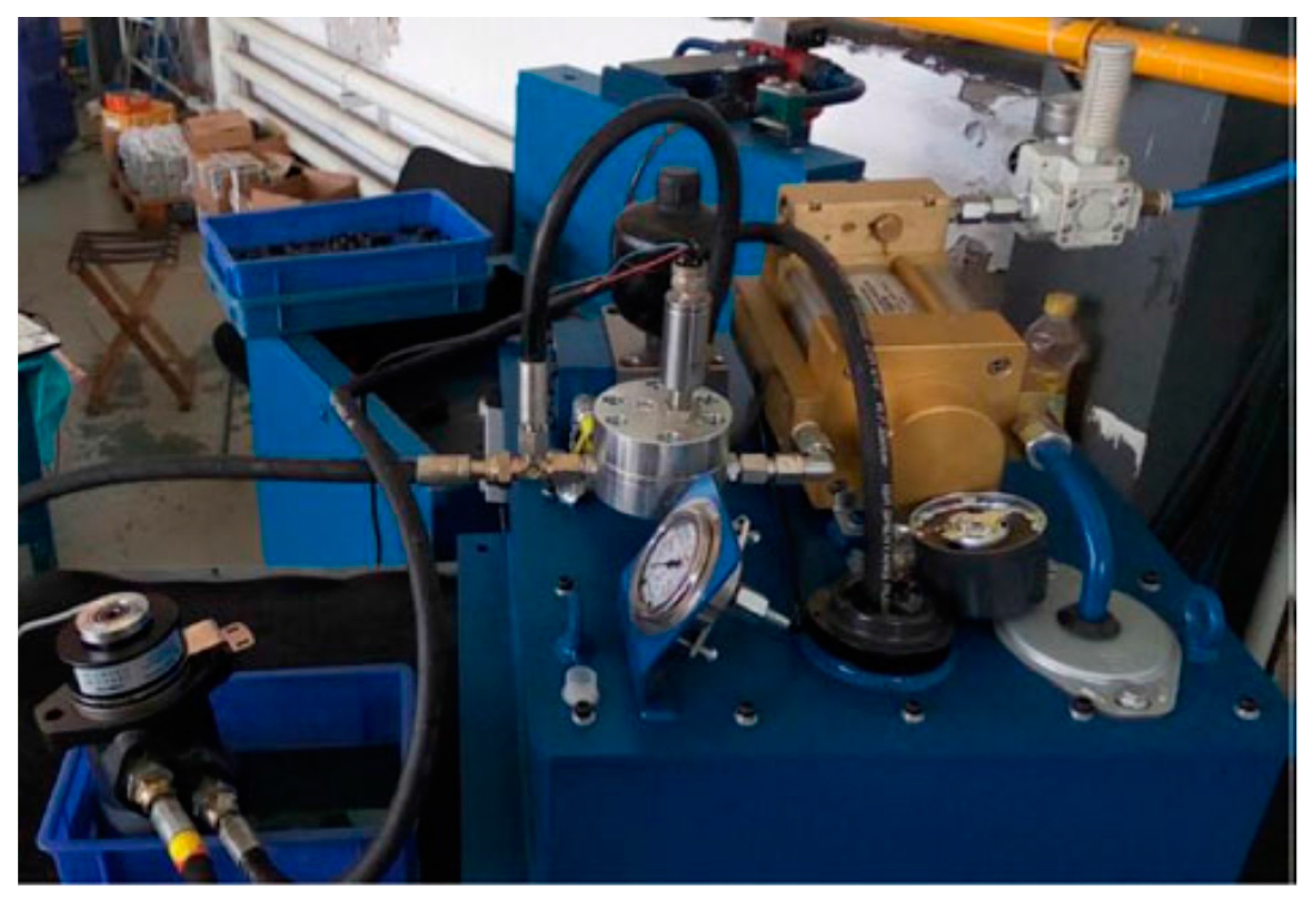
A dedicated test bench for the HP transformer, as shown in Figure 4, was designed and built to measure the output pressure of the HP transformer.
According to previous study [17], because the temperature of the compressed air is almost same as the atmospheric temperature, so the influence of the temperature on the working characteristics of a pneumatic booster can be neglected. As the structure and working principle of the pneumatic booster like the structure and working principle of the HP transformer, in this study, the working process of the HP transformer is considered to be an isothermal process.
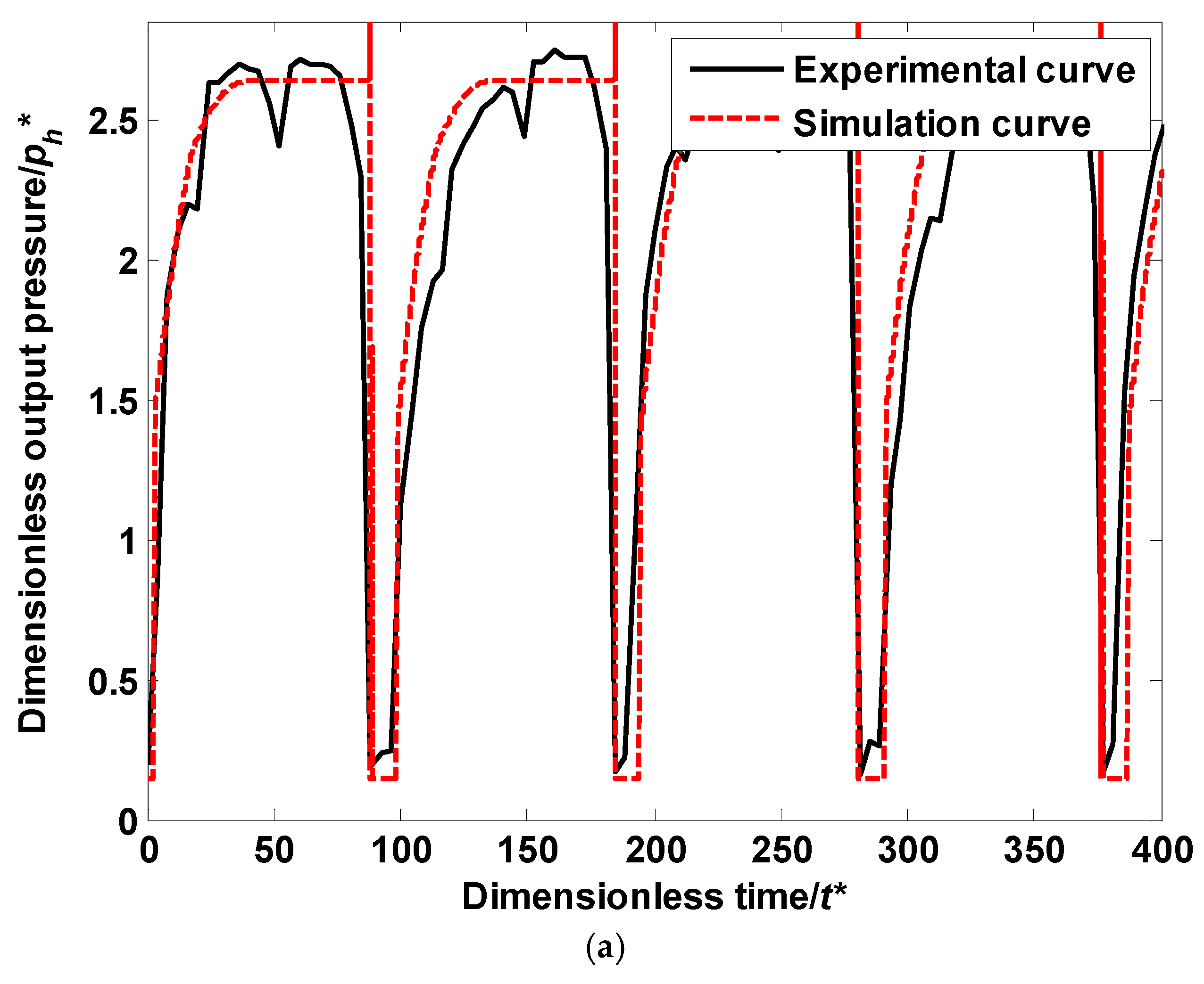
In simulation and experimental study on the HP transformer, the values of the dimensionless area of the hydraulic chamber and dimensionless output oil pressure were set to 0.25 and 2.92. As the output pressure of the HP transformer can be acquired with a pressure sensor, which is more precise and cheaper than a hydraulic flow sensor. Figure 5 depicts the simulation and experimental output hydraulic pressure characteristics.
As shown in Figure 5, it is clear that the simulation results are consistent with the experimental results, and that verifies the mathematical model above. However, there are two differences between the simulation results and the experimental results: (1) The dimensionless output pressure in the experiment results increases more sluggishly than the dimensionless output pressure in the simulation results; (2) There is a fluctuation in the dimensionless output pressure of the HP transformer, when the dimensionless output pressure gets to its top.
The main reasons for the differences are listed as follows. In the experiment, the accumulator absorbed the fluctuation of the dimensionless output pressure, which slowed down the increase of the dimensionless output pressure of the HP transformer. Moreover, the opening size of the relief valve was regulated according to the output pressure of the HP transformer. With a decrease in the output pressure of the HP transformer, the opening size of the relief valve got smaller, then the output pressure of the HP transformer rose accordingly.
5.2. Dynamic Power Characteristics of the HP Transformer
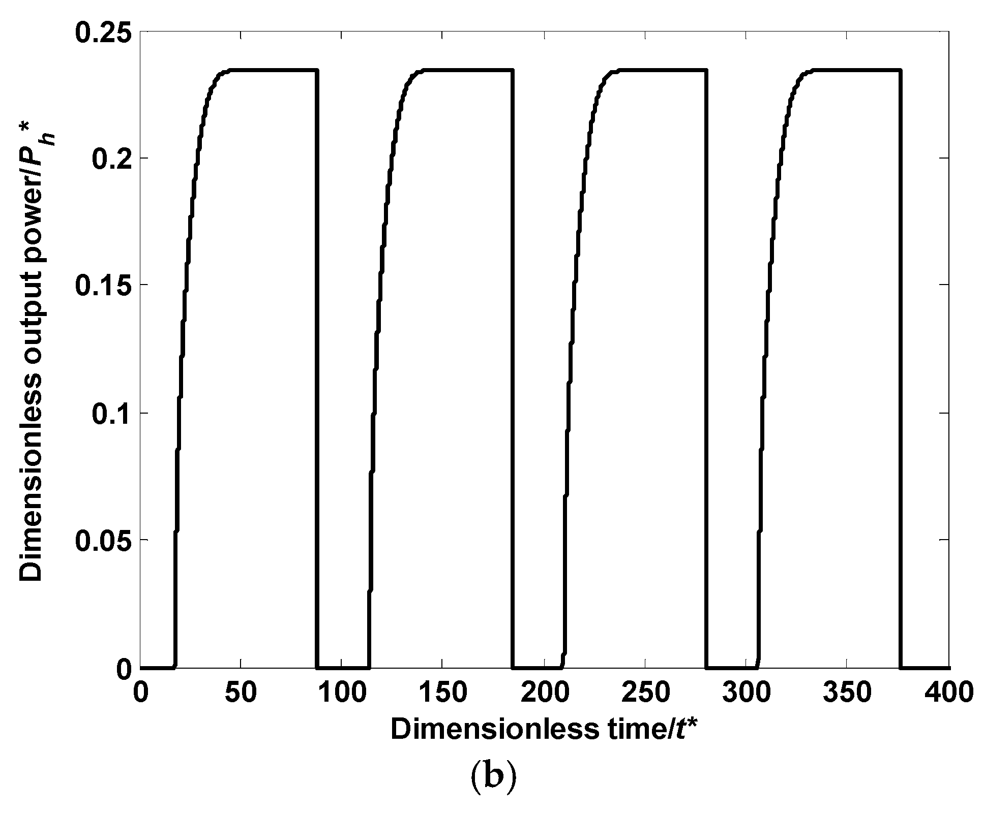
The simulation study on the HP transformer was proceeded according to the study above, and the input power and output power dynamics of the HP transformer can be obtained, which are shown in Figure 6.
As shown in Figure 6, it is clear that, firstly, the dimensionless input power and output power fluctuate regularly. Furthermore, when the HP transformer starts to work when the piston moves from its destination, after a pause, the dimensionless input power and output power increase rapidly and get their platforms. However, when the piston reaches another destination, the dimensionless input power and output power decrease to zero immediately. Finally, as the efficiency coefficient (η0) of HP transformer is about 0.6522, when the dimensionless input power and output power reach their platforms, the efficiency of the HP transformer is 47.52% approximately.
6. Study on the Power and Efficiency of the HP Transformer
Based on the structure and principle of HP transformer, in order to get the parameters which can make the HP transformer better, we carried out the study about the efficiency and output power. After that, the parameters affecting these two properties were clarified.
To illustrate the influence of the dimensionless parameters on the output power and efficiency of HP transformer, each parameter changed for comparison when the other parameters are constant. The values of the dimensionless parameters are shown in Table 2.
6.1. Influence of the Output Pressure
In this part, for getting the change rules of the output power and efficiency when change the output oil pressure, we keep other parameters such as the dimensionless aperture of the hydraulic chamber orifice (set to 0.028), the area ratio of the pistons (set to 4) stay the same when setting the dimensionless output oil pressure to 2.42, 2.57, 2.71, 2.85 and 3.00. After careful analysis and professional simulation study, we get the results shown in Figure 7 and Figure 8. As we can see, curves in Figure 1 depicts the dynamic characteristics of the dimensionless output power, and curve in Figure 8a shows the variation relationship of the dimensionless output power and the dimensionless output oil pressure. Curve in Figure 8b shows the corresponding efficiency of the system with different output oil pressure.
- (1)
- When the dimensionless output oil pressure increases with a proper difference from 2.42 to 3.00, the output power decreases from 0.043 to 0.0322 at the same time. This phenomenon can be explained as the rise of the output oil pressure may result in the decrease of the output flow, so the output oil pressure which is calculated by output flow and output oil pressure decreases.
- (2)
- As we can see in Figure 8, the curves of the dimensionless output power, system efficiency and dimensionless output oil pressure are similar to the trend line.
6.2. Influence of the Aperture of the Orifice of the Hydraulic Chamber
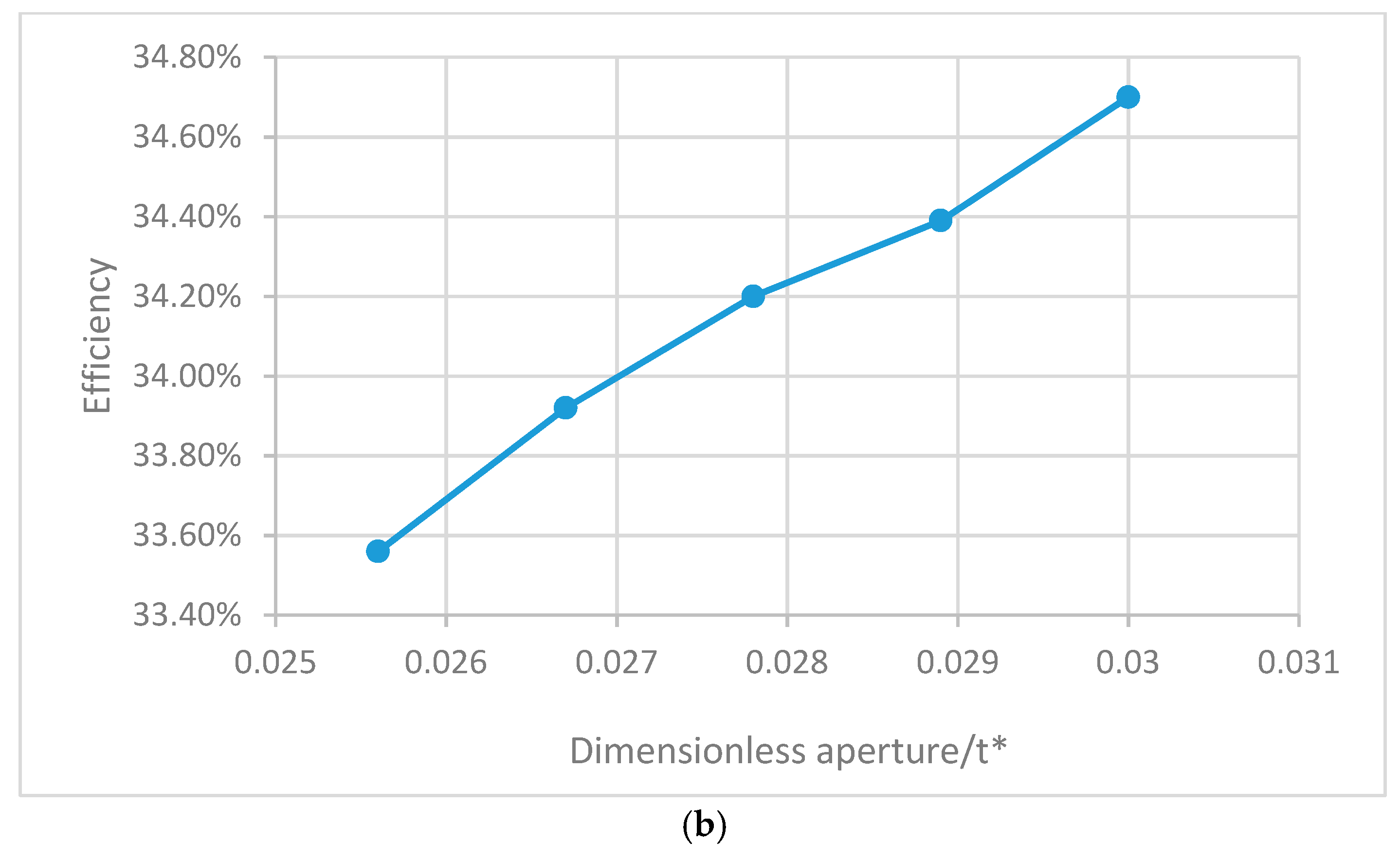
In this part, for getting the change rules of the dimensionless output power and efficiency when change the aperture of the orifice of the hydraulic chamber, we keep other parameters such as the dimensionless output oil pressure (set to 2.71), the area ratio of the pistons (set to 4) stay the same when setting the dimensionless aperture of the orifice of the hydraulic chamber to 0.0256, 0.0267, 0.0278, 0.0289 and 0.030. After careful analysis and professional simulation study, we get the results shown in Figure 9 and Figure 10. As we can see, curves in Figure 9 depicts the dynamic characteristics of the dimensionless output power, and curve in Figure 10a shows the variation relationship of the dimensionless output power and the dimensionless aperture of the orifice of the hydraulic chamber. Curve in Figure 10b shows the corresponding efficiency of the system with different aperture.
- (1)
- When the dimensionless aperture increases with a proper difference from 0.0256 to 0.030, the output power increase from 0.015 to 0.05 and the efficiency increase from 33.56% to 34.7% properly. This phenomenon can be explained as follows: when the aperture of the orifice of the hydraulic increase, the output flow is sure increase, so the output power increase while the output pressure keep constant
- (2)
- As we can see in Figure 10, the curves of the dimensionless output power, system efficiency and dimensionless aperture of the hydraulic chamber orifice are similar to the trendline.
6.3. Influence of the Area Ratio of the Pistons
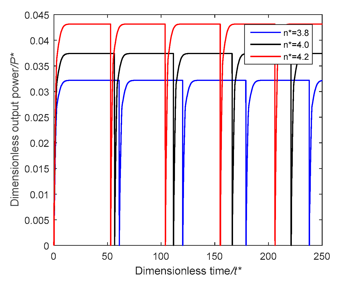
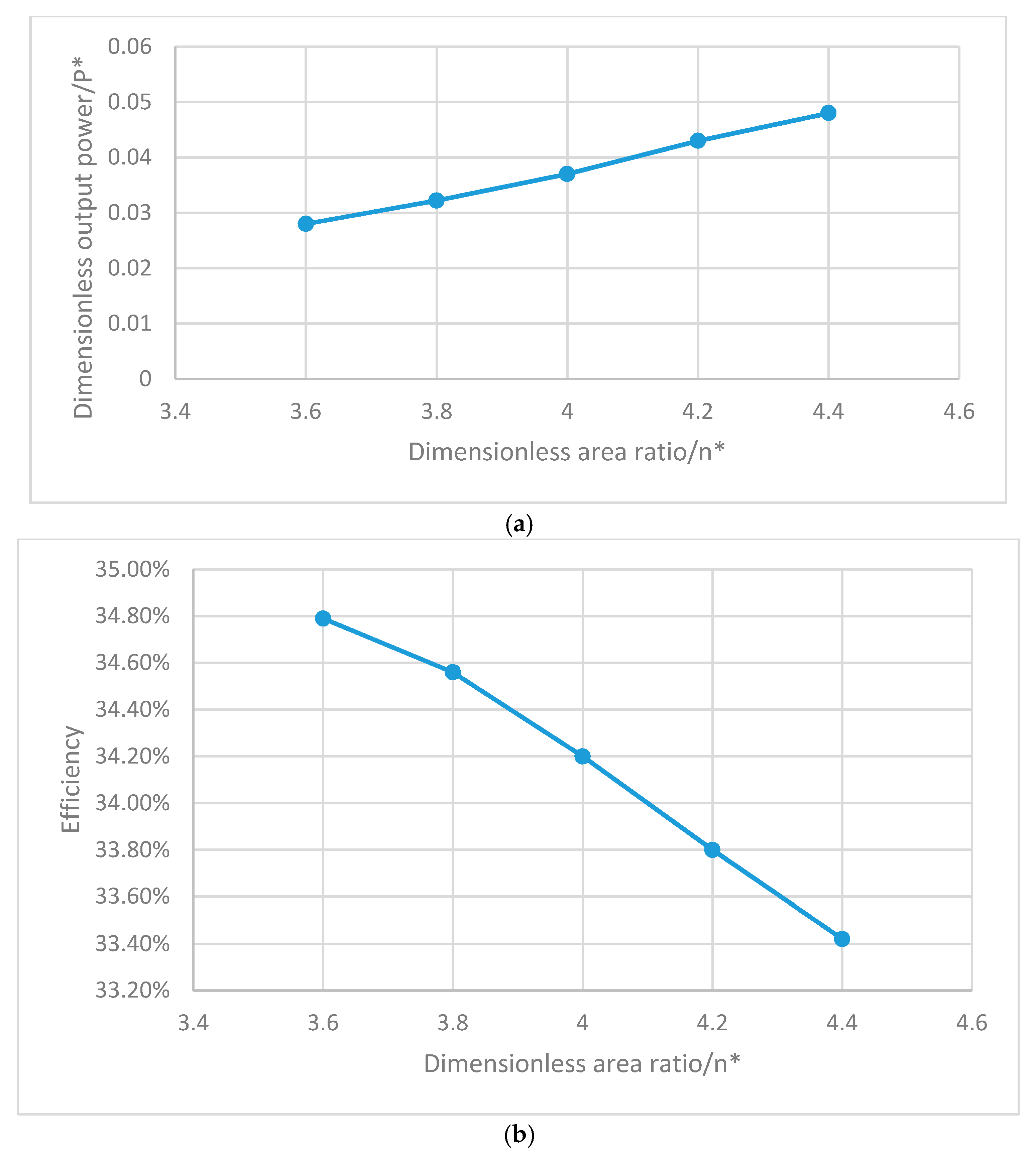
In this part, for getting the change rules of the dimensionless output power and efficiency when change the area ratio of the pistons, we keep other parameters such as the dimensionless output oil pressure (set to 2.71), the dimensionless aperture of the hydraulic chamber orifice (set to 0.028) stay the same when setting the dimensionless area ratio of the pistons to 3.6, 3.8, 4.0, 4.2 and 4.4. After careful analysis and professional simulation study, we get the results shown in Figure 11 and Figure 12. As we can see, curves in Figure 11 depicts the dynamic characteristics of the dimensionless output power, and curve in Figure 12a shows the variation relationship of the dimensionless output power and the area ratio of the pistons. Curve in Figure 12b shows the corresponding efficiency of the system with different area ratio of the pistons.
- (1)
- With the increase of the dimensionless area ratio of the pistons, the output power increases from 0.028 to 0.048 while the efficiency decreases from 34.79% to 33.42%. This is because when the area of the pneumatic piston is constant and the area of the hydraulic piston increase, the output pressure increases correspondingly. So the output power, which is calculated by output pressure and output flow, will increase.
- (2)
7. Conclusions
In this study, a dimensionless mathematic model of the power systems of air-powered hydraulic vehicle was set up. The dimensionless model, which is different from the original model, has many advantages: firstly, unit conversion needs to be considered when the original model is calculated, but the dimensionless model is clearly easy; secondly, the dimensionless model is convenient to make the comparison of parameters, but the original model plays opposite.
To confirm the dimensionless mathematic model, a protocol was built and studied. Through experimental and simulation studies on the power system of air-powered hydraulic vehicle, it can be obtained as follows:
- (1)
- The experimental curve of the archetype has a good match with the simulation curve of the dimensionless model, so it can be derived that the mathematical model is effective and accurate.
- (2)
- When the dimensionless output pressure increase from 2.42 to 3.00, the dimensionless output power decrease from 0.043 to 0.0322, while the system efficiency increase from 33.54% to 34.8%.
- (3)
- While the dimensionless aperture increases from 0.0256 to 0.030, the dimensionless output power increase from 0.015 to 0.05, the system efficiency increase from 33.56% to 34.7% at the same time.
- (4)
- When the area ratio of the pistons increase from 3.6 to 4.4, the dimensionless output power increase from 0.028 to 0.048, and the system efficiency decrease from 34.79% to 33.42% properly.
From the simulation and analysis, we can get the conclusion that the increase of the aperture of the hydraulic chamber orifice and the area of the pistons can lead to a higher output power, and the increase of the output pressure and the aperture of the hydraulic chamber orifice can lead to a higher efficiency.
This research can be referred to in the performance and design optimization of the HP transformer.
Author Contributions
Dongkai Shen carried on all the simulation and experiment works, and he drew the conclusion of this article. Qilong Chen writes the manuscript, and in addition, he drew the pictures and tables of this paper. Yixuan Wang comes up with the method of this project, and he is responsible for the handling work of this article as the corresponding autho.
Conflicts of Interest
The authors declare no conflict of interest.
References
- Yu, Q.; Shi, Y.; Cai, M.; Xu, W. Fuzzy logic speed control for the engine of an air-powered vehicle. Adv. Mech. Eng. 2016, 8. [Google Scholar] [CrossRef]
- Hung, Y.H.; Chen, J.H.; Wu, C.H.; Chen, S.Y. System design and mechatronics of an air supply station for air-powered scooters. Comput. Electr. Eng. 2016, 54, 185–194. [Google Scholar] [CrossRef]
- Wijngaarden, L.V. On the equations of motion for mixtures of liquid and gas bubbles. J. Fluid Mech. 2006, 33, 465–474. [Google Scholar] [CrossRef]
- Zhao, P.; Dai, Y.; Wang, J. Design and thermodynamic analysis of a hybrid energy storage system based on A-CAES (adiabatic compressed air energy storage) and FESS (flywheel energy storage system) for wind power application. Energy 2014, 70, 674–684. [Google Scholar] [CrossRef]
- Naranjo, J.; Kussul, E.; Ascanio, G. A new pneumatic vanes motor. Mechatronics 2010, 20, 424–427. [Google Scholar] [CrossRef]
- Zang, Y.J.; Polytechnic, S. Design and Analysis of a New Type Bidirectional Pneumatic-hydraulic Pressurization System. Hydraul. Pneum. Seals 2013, 9, 57–58. [Google Scholar]
- Shi, Y.; Wu, T.; Cai, M.; Liu, C. Modelling and study on the output flow characteristics of expansion energy used hydropneumatic transformer. J. Mech. Sci. Technol. 2016, 30, 1163–1170. [Google Scholar] [CrossRef]
- Niu, J.L.; Shi, Y.; Cao, Z.X.; Cai, M.L.; Wei, C.; Zhu, J. Study on air flow dynamic characteristic of mechanical ventilation of a lung simulator. China Technol. Sci. 2017, 60, 1–8. [Google Scholar]
- Pimm, A.J.; Garvey, S.D.; Jong, M.D. Design and testing of Energy Bags for underwater compressed air energy storage. Energy 2014, 66, 496–508. [Google Scholar] [CrossRef]
- Cai, M.; Kawashima, K.; Kagawa, T. Power Assessment of Flowing Compressed Air. J. Fluids Eng. 2006, 128, 40–405. [Google Scholar] [CrossRef]
- Li, J.; Li, C.F.; Zhang, Y.X.; Yue, H.G. Compressed air energy storage system exergy analysis and its combined operation with nuclear power plants. Appl. Mech. Mater. 2013, 448, 2786–2789. [Google Scholar] [CrossRef]
- Zheng, X.; Xie, L.; Liu, L. Stability Analysis of Pneumatic Cabin Pressure Regulating System with Complex Nonlinear Characteristics; Hindawi Publishing Corp: Cairo, Egypt, 2015. [Google Scholar]
- Lafmejani, A.S.; Masouleh, M.T.; Kalhor, A. An experimental study on friction identification of a pneumatic actuator and dynamic modeling of a proportional valve. In Proceedings of the IEEE International Conference on Robotics and Mechatronics, Hefei/Tai’an, China, 27–31 August 2017. [Google Scholar]
- Yang, F.; Li, G.; Hua, J.; Li, X.; Kagawa, T. A New Method for Analysing the Pressure Response Delay in a Pneumatic Brake System Caused by the Influence of Transmission Pipes. Appl. Sci. 2017, 7, 941. [Google Scholar] [CrossRef]
- Shi, Y.; Zhang, B.; Cai, M.; Zhang, D. Numerical Simulation of volume-controlled mechanical ventilated respiratory system with two different lungs. Int. J. Numer. Methods Biomed. Eng. 2016, 33, 2852. [Google Scholar] [CrossRef] [PubMed]
- Shi, Y.; Cai, M.L. Dimensionless study on outlet flow characteristics of an air-driven booster. J. Zhejiang Univ. Sci. A 2012, 13, 481–490. [Google Scholar] [CrossRef]
- Vaezi, M.; Izadian, A. Control of a hydraulic wind power transfer system under disturbances. In Proceedings of the IEEE International Conference on Renewable Energy Research and Application, Bandung, Indonesia, 5–7 October 2015; pp. 886–890. [Google Scholar]
- Shi, Y.; Wang, Y.X.; Cai, M.L.; Zhang, B.L.; Zhu, J. An aviation oxygen supply system based on a mechanical ventilation model. Chin. J. Aeronaut. 2018, 31, 197–204. [Google Scholar] [CrossRef]
- Ren, S.; Cai, M.; Shi, Y.; Xu, W.; Zhang, X.D. Influence of Bronchial Diameter Change on the airflow dynamics Based on a Pressure-controlled Ventilation System. Int. J. Numer. Methods Biomed. Eng. 2017. [Google Scholar] [CrossRef] [PubMed]
- Ren, S.; Shi, Y.; Cai, M.; Xu, W. Influence of secretion on airflow dynamics of mechanical ventilated respiratory system. IEEE/ACM Trans. Comput. Biol. Bioinform. 2017. [Google Scholar] [CrossRef] [PubMed]
- Shi, Y.; Zhang, B.; Cai, M.; Xu, W. Coupling Effect of Double Lungs on a VCV Ventilator with Automatic Secretion Clearance Function. IEEE/ACM Trans. Comput. Biol. Bioinform. 2017. [Google Scholar] [CrossRef] [PubMed]
- Shi, Y.; Wu, T.; Cai, M.; Wang, Y.; Xu, W. Energy conversion characteristics of a hydropneumatic transformer in a sustainable-energy vehicle. Appl. Energy 2016, 171, 77–85. [Google Scholar] [CrossRef]
Figure 1.
Composition of the compressed air-powered vehicle: 1 Air source; 2 Pressure governor; 3 Silencer; 4 Electromagnetic directional valve; 5 Accumulator; 6 Hydraulic motor; 7 Retaining valve; 8 Left hydraulic cylinder; 9 Pneumatic cylinder; 10 Right hydraulic cylinder; 11 Mechanical part.
Figure 1.
Composition of the compressed air-powered vehicle: 1 Air source; 2 Pressure governor; 3 Silencer; 4 Electromagnetic directional valve; 5 Accumulator; 6 Hydraulic motor; 7 Retaining valve; 8 Left hydraulic cylinder; 9 Pneumatic cylinder; 10 Right hydraulic cylinder; 11 Mechanical part.

Figure 2.
The forces on the piston of the HP (hydropneumatic) transformer.

Figure 3.
Schematic structure of the HP transformer: (1) Regulator; (2) HP transformer; (3) Accumulator; (4) Silencer; (5) Tank; (6) Data acquisition card; (7) Pressure sensor; (8) Computer; (9) Relief valve.
Figure 3.
Schematic structure of the HP transformer: (1) Regulator; (2) HP transformer; (3) Accumulator; (4) Silencer; (5) Tank; (6) Data acquisition card; (7) Pressure sensor; (8) Computer; (9) Relief valve.

Figure 4.
Dedicated test bench for the HP transformer.

Figure 5.
Simulation and experimental contrast curves. (a) Simulation and experimental curves of the dimensionless output hydraulic pressure; (b) Simulation and experimental curves of the dimensionless flow.
Figure 5.
Simulation and experimental contrast curves. (a) Simulation and experimental curves of the dimensionless output hydraulic pressure; (b) Simulation and experimental curves of the dimensionless flow.

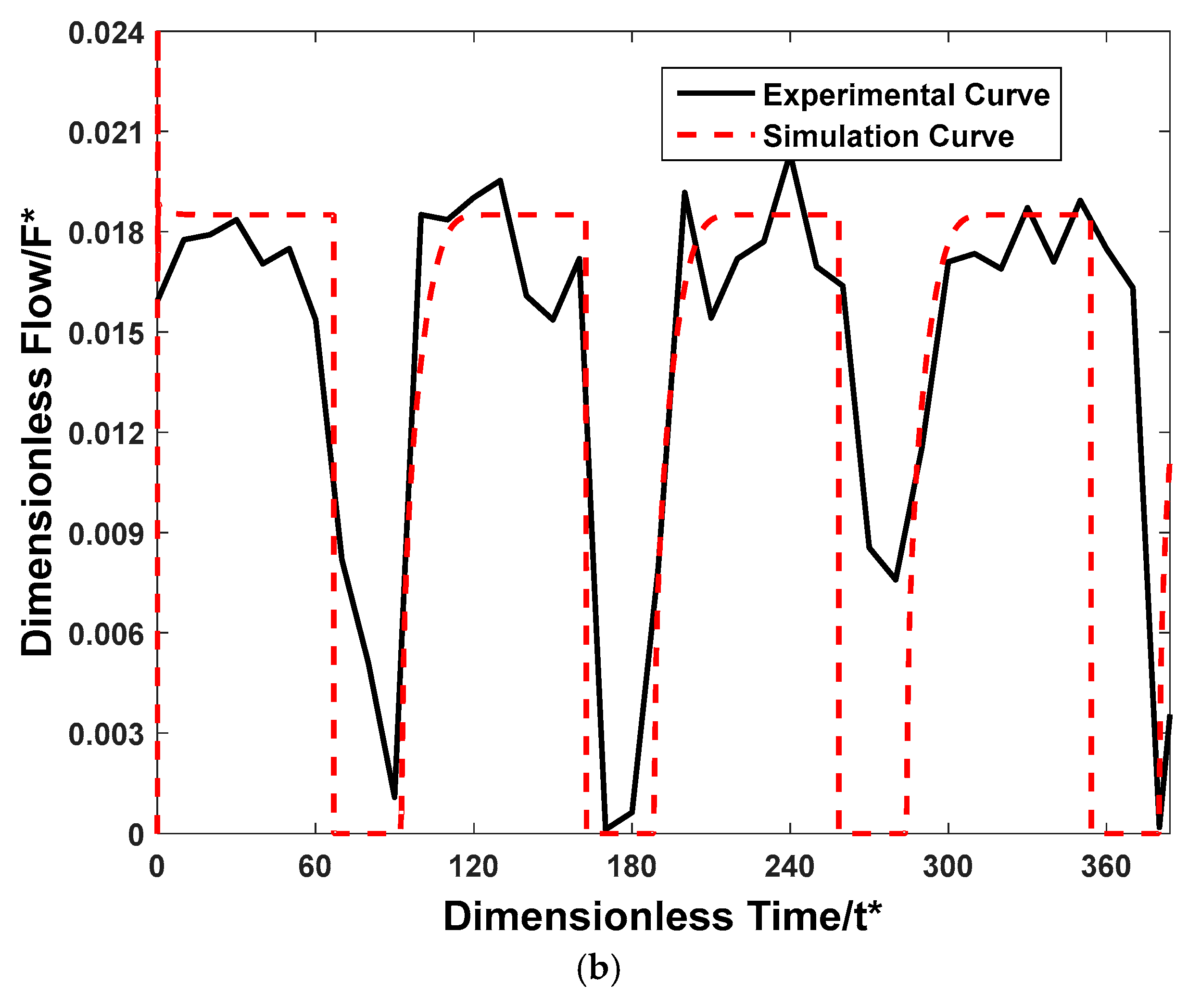
Figure 6.
Dimensionless input power output power characteristics of the HP transformer. (a) Dimensionless input power of the HP transformer; (b) Dimensionless output power of the HP transformer.
Figure 6.
Dimensionless input power output power characteristics of the HP transformer. (a) Dimensionless input power of the HP transformer; (b) Dimensionless output power of the HP transformer.
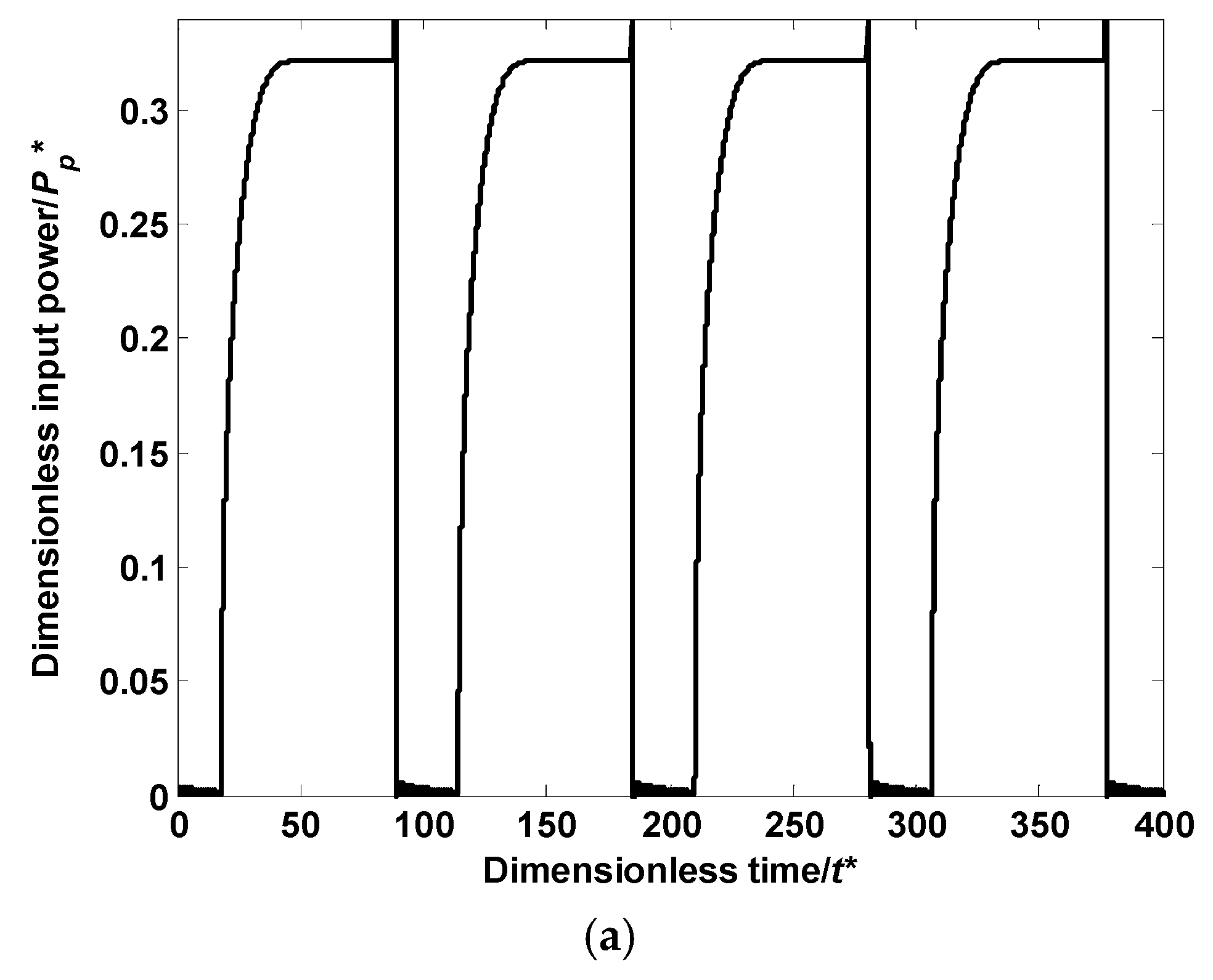

Figure 7.
Dimensionless output power–time curves of the power system.
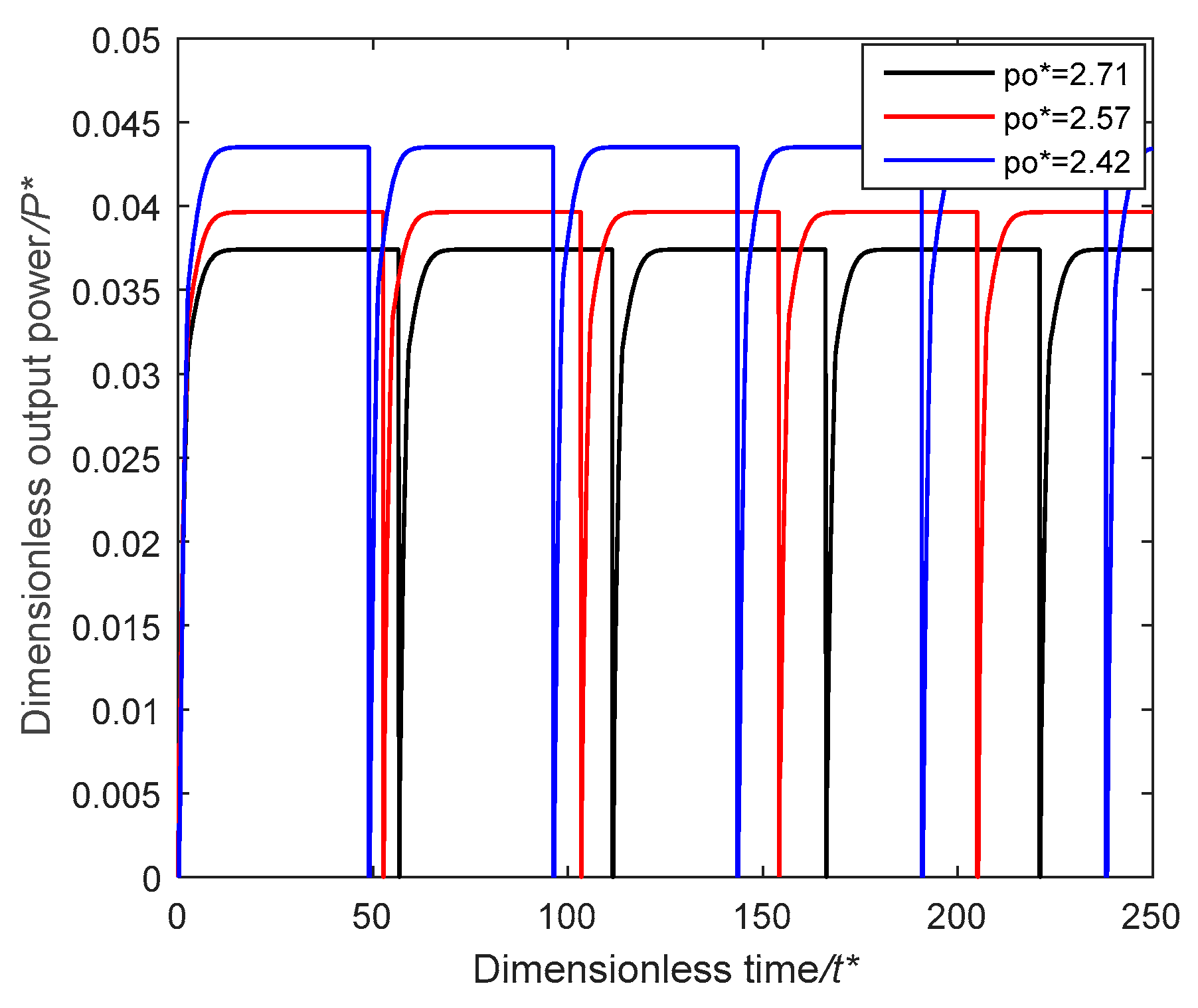
Figure 8.
Relationships of the output power, efficiency and the output pressure. (a) Output power trend curve influenced by the output pressure; (b) Efficiency trend curve influenced by the output pressure.
Figure 8.
Relationships of the output power, efficiency and the output pressure. (a) Output power trend curve influenced by the output pressure; (b) Efficiency trend curve influenced by the output pressure.
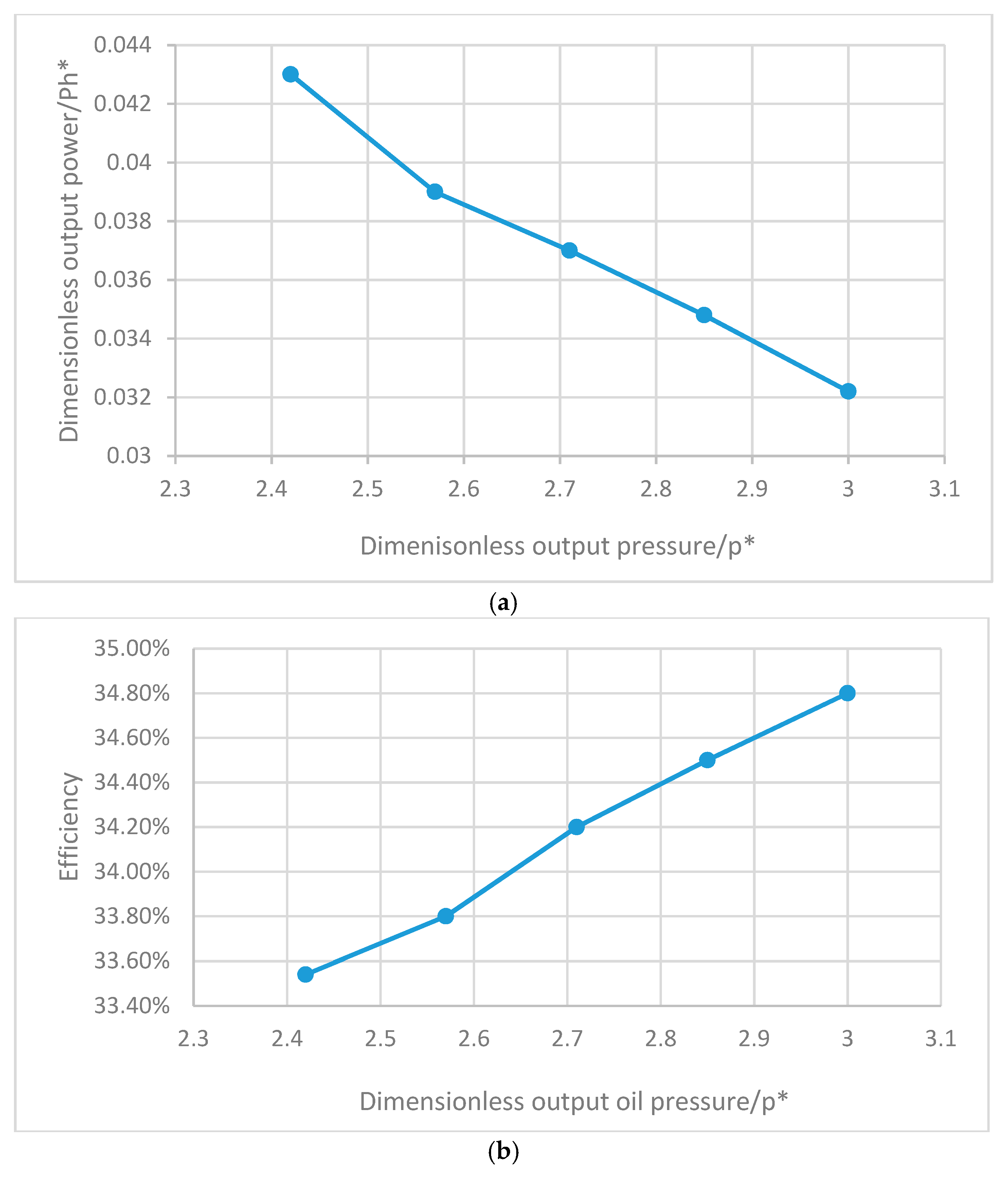
Figure 9.
Dimensionless output power–time curves of the power system.
Figure 10.
Relationships of dimensionless output power, efficiency and the aperture of the orifice of the hydraulic chamber. (a) Output power trend curve influenced by the aperture of the orifice of the hydraulic chamber; (b) Efficiency trend curve influenced by the aperture of the orifice of the hydraulic chamber.

Figure 11.
Dimensionless output power–time curves of the power system.

Figure 12.
Relationships of the output power, efficiency and the area ratio of the pistons. (a) Output power trend curve influenced by the area ratio of the pistons; (b) Efficiency trend curve influenced by the area ratio of the pistons.
Figure 12.
Relationships of the output power, efficiency and the area ratio of the pistons. (a) Output power trend curve influenced by the area ratio of the pistons; (b) Efficiency trend curve influenced by the area ratio of the pistons.


Table 1.
Reference values and dimensionless variables.
| Variable | Reference Value | Dimensionless Variable | |
|---|---|---|---|
| Affective area | Ap | Area of e piston of the pneumatic chamber | |
| Time | tmin | Time to totally exhaust Wb of air at Gmax of air mass flow | |
| Velocity | Average velocity | ||
| Pressure | Ps | Supply pressure | |
| Temperature | Ta | Atmosphere temperature | |
| Air mass flow | Maximum air mass flow | ||
| Volume flow | Maximum oil volume flow | ||
| Air mass | Maximum air mass | ||
| Displacement | L | Piston stroke | |
| Volume | Maximum volume of pneumatic chamber | ||
| Power of compressed air | Maximum power of compressed air | ||
| Power of hydraulic oil | Maximum power of hydraulic oil when its pressure equals the supply pressure (ps) | ||
Table 2.
Values of the dimensionless parameters.
| Parameters | Tf* | Fs* | C* | Fc* | Ah* | Po* | Aeh* |
|---|---|---|---|---|---|---|---|
| Values | 0.1425 | 0.00018 | 0.0004 | 0.00036 | 0.25 | 2.857 | 0.000625 |
© 2018 by the authors. Licensee MDPI, Basel, Switzerland. This article is an open access article distributed under the terms and conditions of the Creative Commons Attribution (CC BY) license (http://creativecommons.org/licenses/by/4.0/).
Share and Cite
MDPI and ACS Style
Shen, D.; Chen, Q.; Wang, Y. Dimensionless Energy Conversion Characteristics of an Air-Powered Hydraulic Vehicle. Appl. Sci. 2018, 8, 347. https://doi.org/10.3390/app8030347
AMA Style
Shen D, Chen Q, Wang Y. Dimensionless Energy Conversion Characteristics of an Air-Powered Hydraulic Vehicle. Applied Sciences. 2018; 8(3):347. https://doi.org/10.3390/app8030347
Chicago/Turabian StyleShen, Dongkai, Qilong Chen, and Yixuan Wang. 2018. "Dimensionless Energy Conversion Characteristics of an Air-Powered Hydraulic Vehicle" Applied Sciences 8, no. 3: 347. https://doi.org/10.3390/app8030347
Note that from the first issue of 2016, this journal uses article numbers instead of page numbers. See further details here.