A Vector Printing Method for High-Speed Electrohydrodynamic (EHD) Jet Printing Based on Encoder Position Sensors


1
Department of Electronics Material and Devices Engineering, Soonchunhyang University, 22, Soonchunhyang-Ro, Shinchang, Asan, Chungnam 336-745, Korea
2
Department of Mechanical Engineering, Soonchunhyang University, 22, Soonchunhyang-Ro, Shinchang, Asan, Chungnam 336-745, Korea
*
Author to whom correspondence should be addressed.
Appl. Sci. 2018, 8(3), 351; https://doi.org/10.3390/app8030351
Submission received: 11 February 2018
/
Revised: 26 February 2018
/
Accepted: 26 February 2018
/
Published: 28 February 2018
(This article belongs to the Special Issue Printed Electronics 2017)
Abstract
:Electrohyrodynamic (EHD) jet printing has been widely used in the field of direct micro-nano patterning applications, due to its high resolution printing capability. So far, vector line printing using a single nozzle has been widely used for most EHD printing applications. However, the application has been limited to low-speed printing, to avoid non-uniform line width near the end points where line printing starts and ends. At end points of line vector printing, the deposited drop amount is likely to be significantly large compared to the rest of the printed lines, due to unavoidable acceleration and deceleration. In this study, we proposed a method to solve the printing quality problems by producing droplets at an equally spaced distance, irrespective of the printing speed. For this purpose, an encoder processing unit (EPU) was developed, so that the jetting trigger could be generated according to user-defined spacing by using encoder position signals, which are used for the positioning control of the two linear stages.
1. Introduction
The electrohydrodynamic-jet (EHD jet) has emerged as a fine patterning tool for various applications [1]. The EHD jet process uses the high DC voltage applied at the nozzle part to charge ink and produce an electrical field for jetting [2,3,4,5,6]. For drop-on-demand (DOD) EHD jetting, an additional pulse voltage has been used to produce one droplet per pulse voltage. To design the pulse voltage shape for proper jetting, Mishra et al. proposed a pulse width modulation method [5], whilst Kwon et al. presented the use of trapezoidal pulse voltage [6]. For EHD printing, most previous works have used AC or pulse voltage with constant frequency [4,5,6,7,8]. In such cases, there will be a large amount of deposited droplets at the starting and end points, which is caused by printing speed variation. Uniformity in the printed pattern is important for most fine patterning applications, including conductive patterning, semi-conductor applications, and repair application for broken circuits. As a result, the EHD applications can be limited to the case of low printing speed, and there has been a trade-off relationship between the printing speed and print quality. Nevertheless, to the best of the author’s knowledge, few papers have discussed the printing uniformity issue of the end points of the EHD printed lines.
In the case of conventional piezo-based inkjet application, the encoder signals (positioning sensors in stages) have been used for bitmap printing to obtain equally spaced printing irrespective of the printing speed. However, the conventional inkjet printing uses only one axis of the encoder signal for the main direction printing, while the other axis is used for movement of the printing location for the next swath. The conventional method using encoder signals from a single axis is useful to print bitmap images by using inkjet heads with many nozzles. However, in the case of EHD printing, a single nozzle is more commonly used, since the multi-nozzle EHD head is difficult to implement, because of the electrical crosstalk effects from adjacent nozzles. In such a case, vector printing using a single nozzle rather than bitmap image printing is more suitable for its application. Vector printing commonly involves the vector motion of stages that require the simultaneous movement of more than two axes. Therefore, the hardware and software algorithm requirements for vector printing should be different from those for bitmap printing.
In this article, we propose a new vector printing method for EHD jet printing to print uniform lines by printing dots with equal spacing, irrespective of printing speed variation. For this purpose, the jetting trigger pulses are generated at each equally spaced distance based on two position encoder sensors. Here, two different approaches are proposed: (1) the printing method, including acceleration and deceleration regions; and (2) the printing method using only the constant printing speed region, excluding the acceleration and deceleration regions. To implement the proposed method, a so-called encoder processing unit (EPU) and a built-in computer-aided design (CAD) printing software were developed, so that positioning sensors from two axes (two encoder signals) could generate the trigger pulses at each pre-set distance along the printing line. Finally, we compared our proposed printing methods with the conventional method by investigating the end points of the printed lines according to the printing speed.
2. Vector Printing Method Using the Encoder Sensors of Two Axes
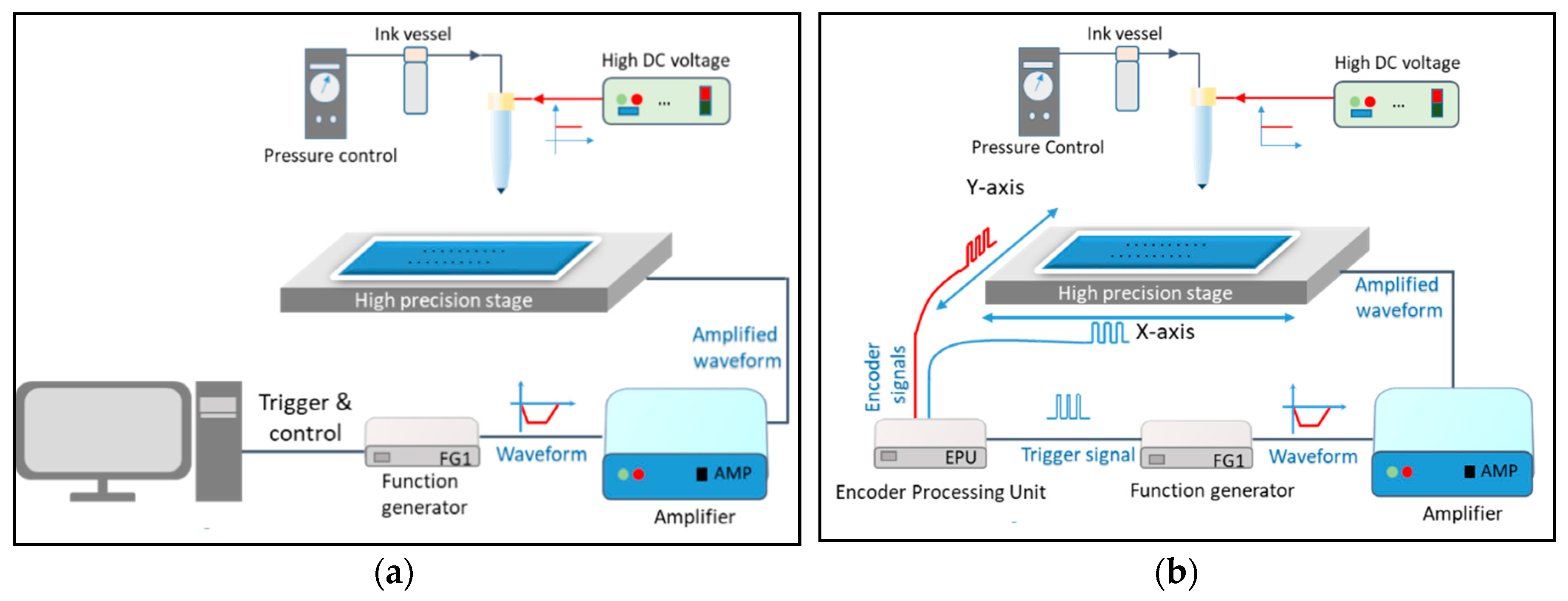
Figure 1 compares the conventional EHD jetting systems with our proposed system using encoder position signals for jetting. Both systems in Figure 1 use air pressure at the ink reservoir to supply the ink to the nozzle and maintain the extruded meniscus at the nozzle tip during the printing process. A DC voltage is applied to the nozzle part as a background voltage to charge the ink and maintain the stand-by meniscus position on the nozzle. Then, a negative trapezoidal pulse voltage connected to the substrate holder is used to generate a droplet per single trigger [6]. There can be two different approaches regarding the generation of trigger pulses: (1) jetting trigger based on constant frequency (the conventional approach), as shown in Figure 1a; and (2) jetting trigger based on constant spacing using position sensors (the proposed method), as shown in Figure 1b. In this study, the two approaches are discussed and compared in terms of hardware implementation and printed line uniformity.
2.1. Vector Printing without Using Encoder Signal
Although the EHD jet can be produced by using DC voltage only, pulse voltage superposed with DC voltage has been commonly used, since the jetting can be controlled by an external trigger signal. Most previous EHD vector printing methods have been based on AC voltage, or pulse voltage with constant frequency from either external or internal trigger sources [4,5,6,7,8]. In this case, the drop placement spacing between 2 consecutive jettings, ds, can be determined by the motion (printing) speed, v, and the jetting frequency, f, as: . The droplet placement interval (or spacing) is an important parameter to form a connected line using a series of droplets. Note that the drop placement spacing should consider the droplet size deposited on a substrate to form a connected line by overlapping deposited dots. For example, if the deposited dot size on the substrate is d, then the drop placement spacing, , should be around to make connected lines via a slight overlap of the droplets. If the spacing between droplets is too small, the pattern width becomes thick, due to heavy overlapping of droplets. However, if the spacing between droplets becomes more than the deposited droplet size, the deposited dots cannot make connected lines.
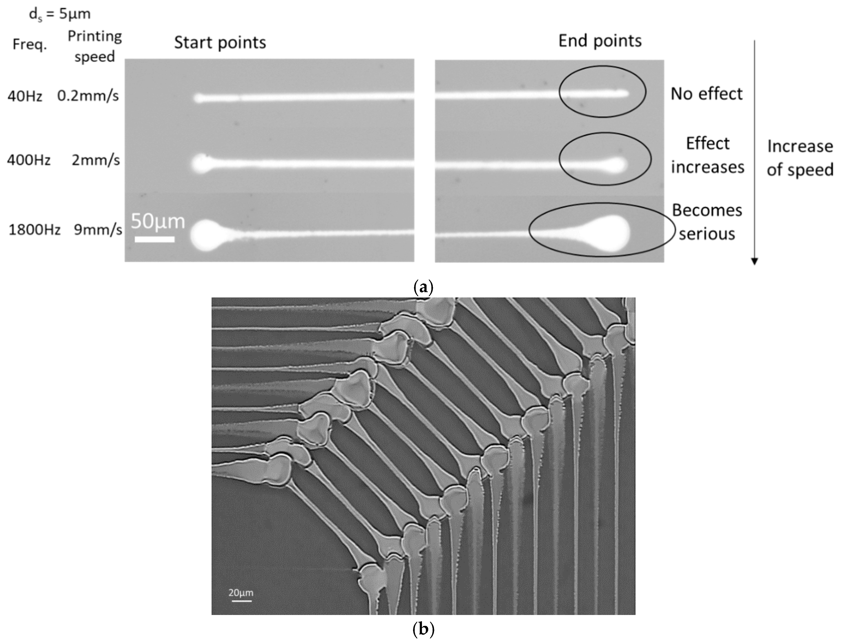
To obtain uniform line width by achieving equally spaced deposited dots, the printing speed needs to be constant throughout the printing region (line) in the case of using constant jetting frequency. However, in order to print at target speed, v, there should be an acceleration or deceleration region at the start point and end point of line, in which the printing speed changes from zero to the target speed, or vice versa. As a result, a significant amount of droplet can be deposited near the start and end points of the printed lines, compared to the rest of the regions. As the target printing speed or jetting frequency increases, the excessive overlapping of dots at the end points becomes more serious. Figure 2 illustrates non-uniformity in printed lines, which is caused by a large amount of droplet deposition at both end points of the line. Figure 3 shows the typical printed lines using the constant frequency method. Figure 3a shows that if the printing speed is low (less than 1 mm/s), the start and end points of the printed line are not significantly influenced by acceleration and deceleration. However, if the printing speed becomes more than 10 mm/s, the amount of droplets deposited at both ends increases significantly, according to the increase of printing speed. Figure 3b shows the printed results of patterns using a printing speed of 30 mm/s. The figure shows that it is difficult to increase the line density (the number of lines per unit distance), due to the large amount of droplets at the end points of the line. As a result, the target printing speed and jetting frequency have been limited to very low (less than 1 mm/s) in order to achieve reasonable printing quality.
2.2. The Method of Using Two Encoder Signals for Vector Printing
To solve the non-uniform printing issues near end points, the droplet spacing distance should remain the same throughout the printing process. For this purpose, we propose the use of two encoder position sensors to generate single channel jetting trigger signals. In the next section, the hardware, as well as software, for the implementation will be discussed in detail.
2.2.1. Development of the Encoder Processing Unit (EPU)
We developed the so-called encoder processing unit (EPU) to generate trigger pulses at each pre-set distance in real-time, as shown in Figure 4. To generate jetting trigger signals based on two encoder signals, the EPU counts the encoder pulses from two stage axes. The maximum allowable rate of the encoder signal is 10 MHz to use the counting functions. In this study, the encoder resolution of the stage was 1 μm, which means the EPU could handle the printing speed of up to 10 m/s, which is sufficient for most EHD applications.
The generated trigger signals for jetting are based on position sensors and are not affected by printing speed variation, including the acceleration and deceleration parts. To change the dot spacing distance and other settings of the EPU via software, we used universal serial bus (USB) communication with personal computer (PC).
For comparison with the conventional method, we prepared one trigger input BNC port (labeled as Enable) to use the external jetting trigger instead of encoder position signals, as shown in Figure 4a. In this way, two modes of “constant distance” using two encoder sensor signals and “constant frequency” using the external trigger could be selected via USB communication with the PC. To use encoder signals from two stages, a 9 D-Sub connector was used to get the position information from encoders, as shown in Figure 4b. Figure 4c shows the wire pin out for the connection. Here, X and Y represent the two moving axes. Each axis has two outputs of A and B, which are 90 degrees out of phase.
Table 1 shows the specifications for using the EPU. The allowed maximum drop spacing distance is 64 pulses of encoder signal. The drop spacing distance is based on the resolution of the encoders. For example, if one encoder pulse corresponds to 1 μm (encoder resolution), then the drop spacing can be from 1 to 64 μm. To print connected lines by using series of drops, each drop should be placed at a distance less than the drop size. For instance, if the dot size of the EHD jet on the substrate is assumed to be 5 μm, the drop spacing would be set to around 3 μm for connected lines using dots, which corresponds to 3 encoder pulses. The encoder resolution used in our study was 1 μm, which is suitable for printing connected lines with micron sized drops. Note that, in some applications using submicron drops [9], the encoder sensors with sub-micrometer resolution should be used.
In the EPU, two functions are implemented to generate an equal-spaced trigger signal: (1) an automatic trigger pulse generation function; and (2) a printing distance counting function, including non-jetting dummy distance.
In the case of automatic pulse generation function, there is no limitation on the printing line length. The method usually includes acceleration and deceleration parts of staged motion to print lines. The on-off control of this mode is controlled by USB communication with the PC.
However, in the case of the printing distance counting function, two additional parameters of dummy length and printing length were used to set up the starting location of printing with respect to the starting point of motion movement and printing line length, respectively. This function is developed to exclude the acceleration and deceleration regions for printing lines. Since it is based on counting the number of pulses, there is a printing line length limitation. In our implementation, the total distance from the start moving to the stop jetting should be smaller than 262,144 encoder pulses, or 262,144 μm, if we use the dot spacing of 1 μm. The implementation method was considered to print our maximum allowable substrate size of (150 mm × 150 mm) in our equipment. Note that this does not mean that it cannot be extended to print larger size pattern.
2.2.2. Two Functions of the EPU
The Automatic Trigger Pulse Generation Function
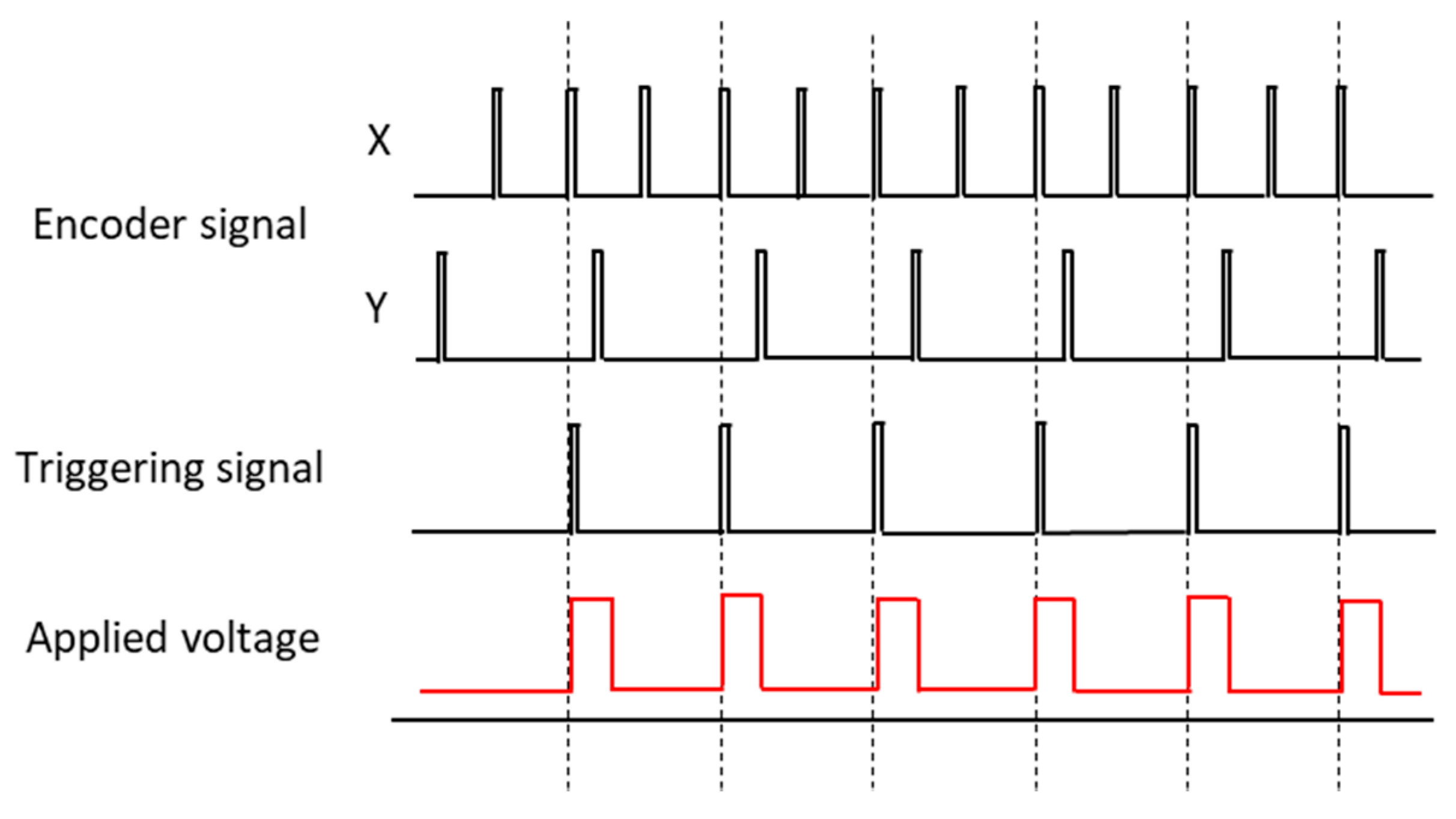
The basic function of the EPU is to generate trigger pulses in real-time at each pre-set drop spacing distance, ds, based on two encoder position signals. Note that for most EHD vector printing applications, simultaneous movement of 2 axes is required. Figure 5 shows the example of printing a line from point to point . The number of generated encoder pulses of x and y axis movements during the printing process can be determined by , , respectively. Here, r is the resolution of the encoder signal. Note that we cannot use two encoder signals directly to generate a single channel jetting trigger. To generate single channel jetting trigger signals from two axes, the EPU counts the number of encoder pulses from the x-axis and y-axis in real-time.
Figure 6 illustrates how the trigger signal for jetting with distance spacing of is generated from two encoder signals. It should be noted that there can be round-off position errors of 0.5 × ds to generate jetting triggers with dot spacing of ds. In the case of connecting lines patterning such as repair applications, the round-off position errors could result in unconnected parts. So, in the case of practical application, additional trigger pulses can be added before starting and after printing the lines to ensure the connectivity of the pattern.
If we use the jetting trigger based on droplet placement distance, ds, the total number of jetting trigger pulses should be . Here, the addition of one extra trigger is added at the initial starting point. This also solves the non-printing problem of print on point A, since there is no encoder counting pulse at the first position of printing.
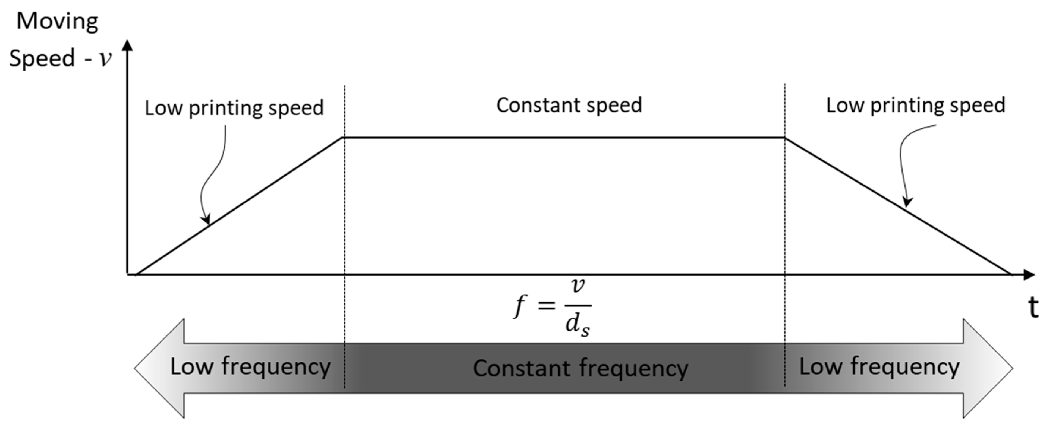
When using the EPU, the jetting frequency, f, is automatically varied according to printing speed, v, as . As a result, the jetting frequency is likely to become very low during the acceleration and deceleration regions, compared to that of the target speed region, as shown in Figure 7.
The use of the EPU is effective for making a uniform line based on equally spaced dot deposition. However, even if the dot spacing is equal, a non-uniform droplet amount could affect the printing quality. Note that the droplet amount may vary according to the jet frequency [6]. To print a uniform line, the amount of jetted droplet should be uniform throughout the line printing. For this purpose, we implemented a printing distance counting function in the EPU, which will be discussed in the next section.
Printing Distance Counting Function
To improve printing quality, we propose the printing method of using a constant jetting frequency region only by excluding the acceleration and deceleration regions.
For the implementation, an additional length, the so-called dummy length, should be added to both ends of patterns to move stages for acceleration and deceleration purpose without printing. In the first dummy region, the EPU counts a pre-set number of non-jetting pulses to skip jetting in the acceleration region. Here, jetting triggering pulses are internally generated at each pre-determined spacing distance and are not connected to output for the EPU for jetting triggering. After finishing counting the dummy length, the jetting trigger will be connected to the output of the EPU, so that the jetting can be generated to print the pre-determined line length. After counting of the jetting trigger for printing, the jetting trigger pulse will no longer be generated, even when the stage is moving for the deceleration region (the latter dummy length).
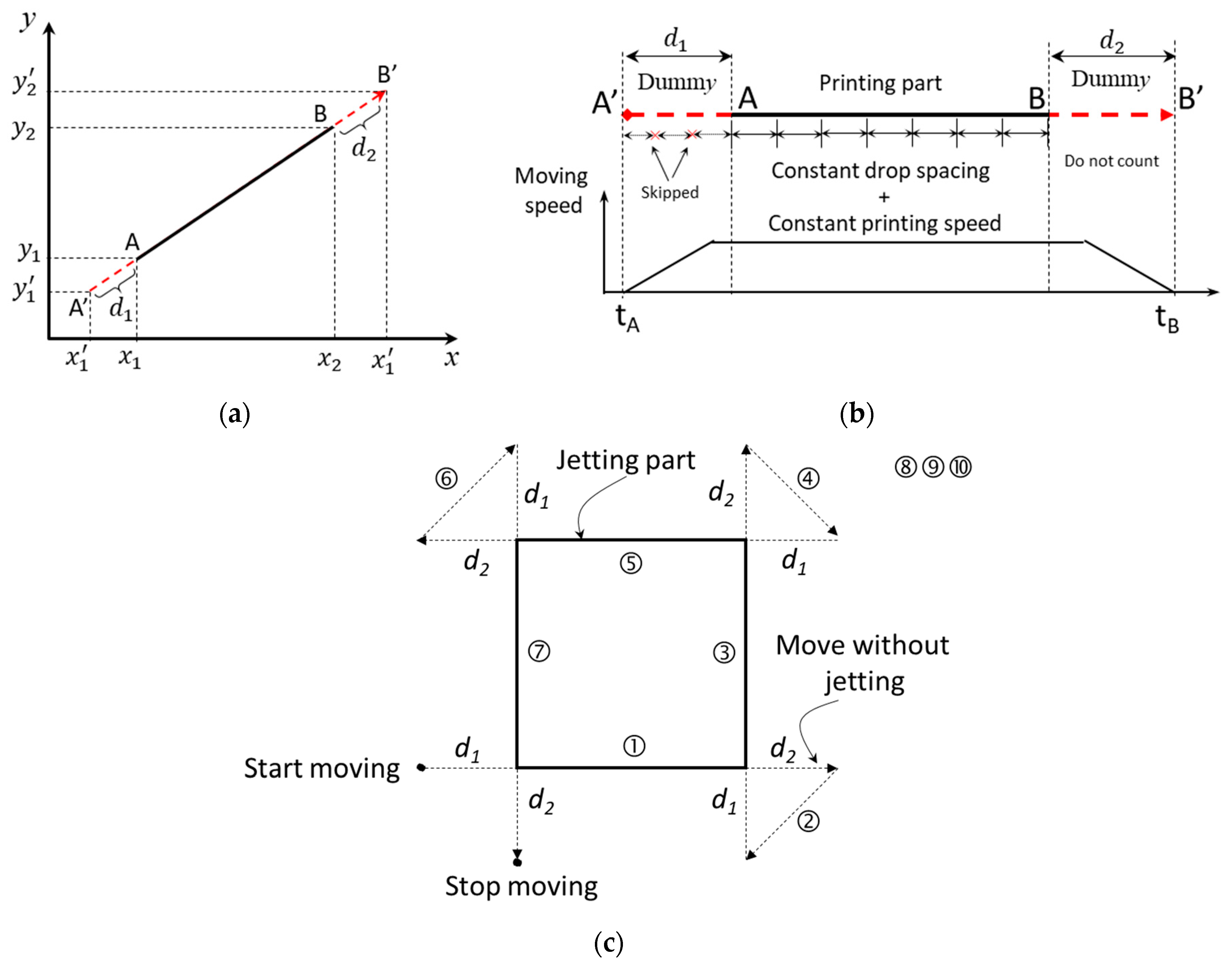
Figure 8 shows the proposed printing method using dummy length to exclude the acceleration and deceleration parts for printing. If we assume that the printing part is from to , the movement should start from to , as shown in Figure 8, so that the dummy distances, d1 and d2, can be added before A and after B, respectively. Note that the jetting pulses at each dot spacing are generated only at the printing region between and . The sufficient dummy distances, d1 and d2, should be considered, such that the acceleration and deceleration can be as , in which v and a are the printing speed and acceleration (or deceleration), respectively. Then, the number of dummy counts based on the dot spacing trigger, ds, would be , and the number of printing counts would be . Note that there will be no more counting during the deceleration region, d2.
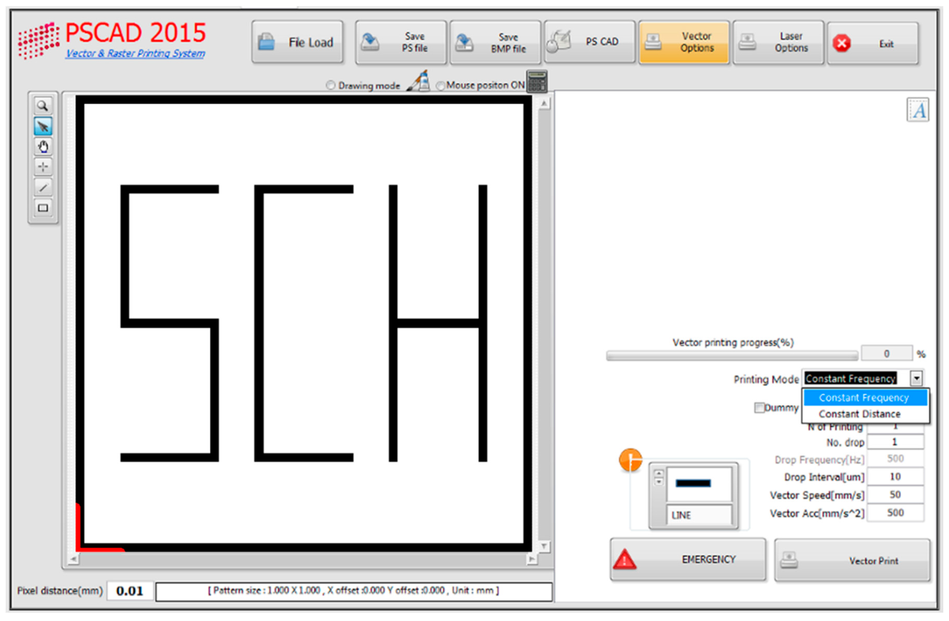
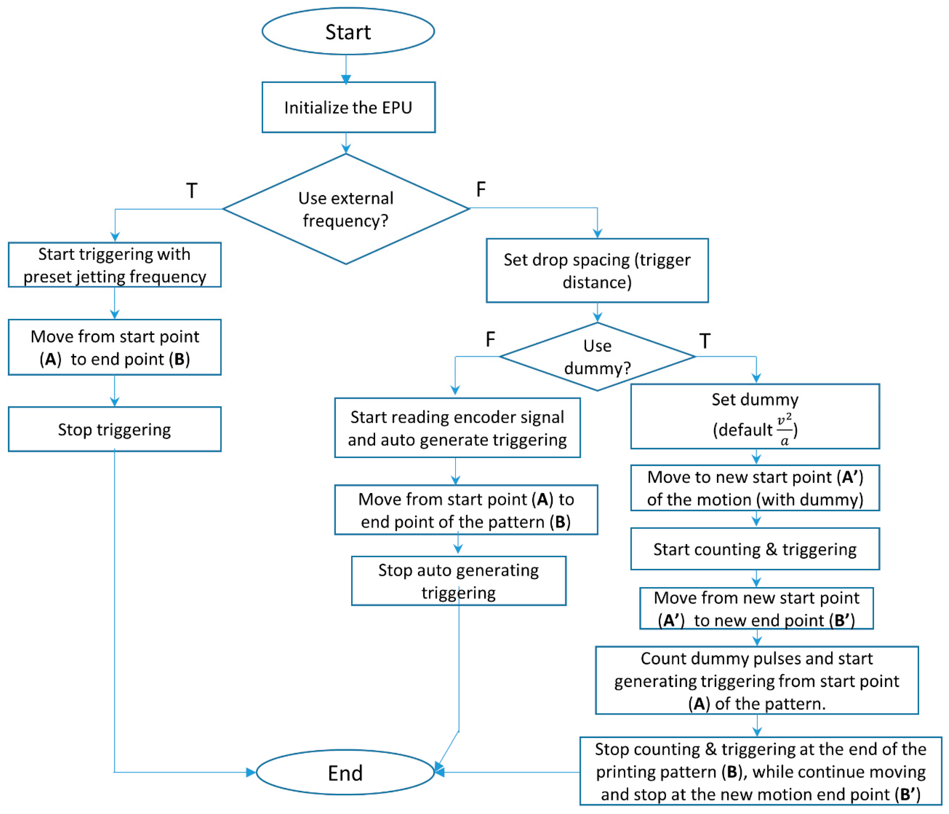
To demonstrate vector printing based on EPU, a CAD-based printing software was developed to select printing mode using “constant frequency” and “constant distance” (using the EPU) as shown in Figure 9. In constant frequency mode, the trigger pulses with constant frequency are generated via the counter in a multi-function board (PCI-6221, National Instrument, Austin, TX, USA). Here, the jetting trigger is independent of stage movement. However, when the constant distance mode is selected to use the proposed EPU function, there are two options, depending on whether the acceleration and deceleration parts are included for printing. Figure 10 shows the flow chart for CAD-based printing lines with (or without) the EPU. Here, the important parameters for line printing would be jetting frequency and drop interval, as well as printing speed, acceleration, and deceleration.
3. Experimental Results and Discussion
To investigate the EPU effects on printing quality, we used the printing parameters of jetting frequency of 500 Hz, target drop placement spacing of 50 µm, and printing speed of 25 mm/s. To clearly understand the effect according to the printing methods, printed dots are intended to be separated as shown in Figure 11. Figure 11a shows the printed result using the conventional constant frequency jetting for comparison purpose. As shown in the figure, the drop spacing increased from zero to target values during the acceleration region. As a result, a large number of droplets are overlapped at the initial part of the pattern. However, in the case of using encoder sensors to generate jetting triggers, there are no significant overlaps at the starting part (Figure 11b,c), and dots are placed at equally spaced distance, irrespective of printing speed.
Figure 11b shows the printed results of using automatic trigger generation, including the acceleration and deceleration parts. This shows that the droplet size is smaller in the initial part in which the printing speed is low and becomes larger in the printing direction, until it reaches the target printing speed. The droplet amount is related to the jet frequency, and it becomes larger as the jet frequency increases [6,8]. Note that in the acceleration and deceleration part, the jetting frequency should be very low to print dots at each equally spaced distance when it is compared to the target printing speed part. On the other hand, Figure 11c shows that using the so-called dummy distance approach significantly improved the droplet size uniformity. Nonetheless, the first droplet is smaller than the rest of the droplets. This might be related to the equivalent DC voltage behavior due to high-frequency pulse voltage, which will be discussed in detail later.
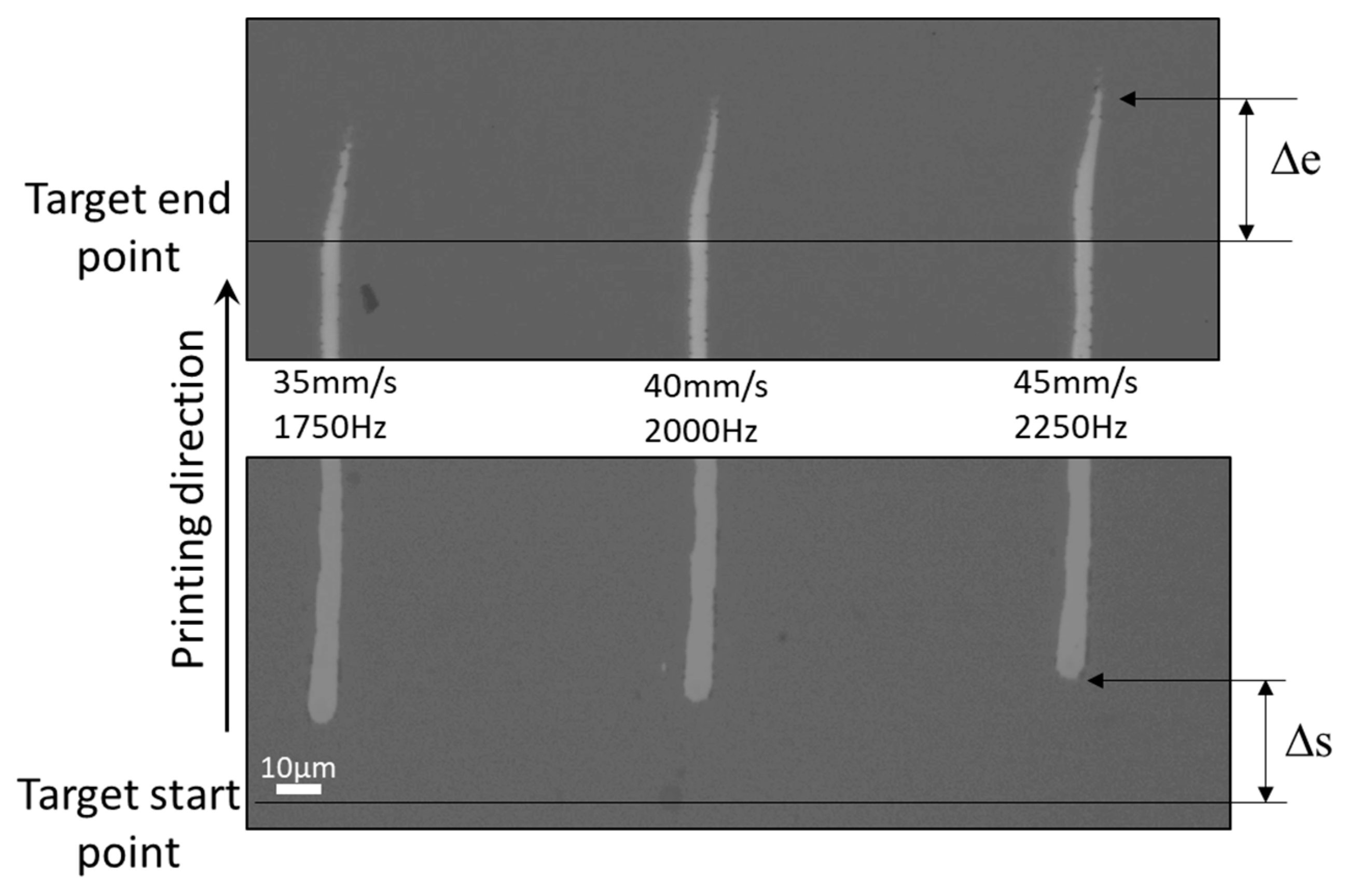
In the case of high jetting frequency of more than 1 kHz and printing speed of more than 30 mm/s, the printing behavior might be slightly different, as shown in Figure 12, which shows that uniform line width at the initial part can be achieved by using the high jetting frequency. Here, dummy length is used to exclude the acceleration and deceleration regions. From the printing results shown in Figure 12, there are two interesting behaviors in the printing using high-frequency jetting: (1) There is printing position shift from the target location, and (2) There is a prolonged tail at the end of the printing line. The position shift is also related to the printing speed and increases slightly according to the printing speed increase.
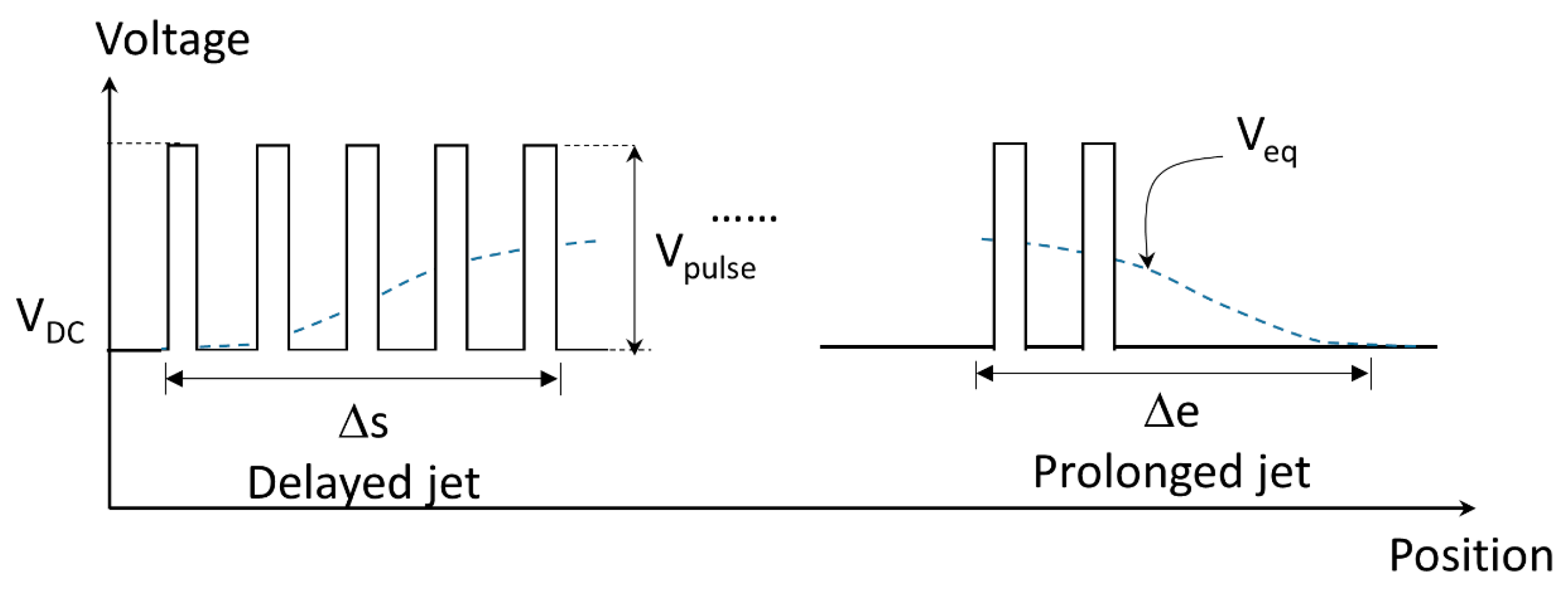
In the case of high-frequency jetting at more than 1.5 kHz, the equivalent DC voltage effects dominate the pulse voltage effects. The equivalent DC voltage effect can be written as:
in which Veq, Vdc, Vp, and Vp_ave and T are the equivalent DC voltage, DC background voltage, pulse voltage for jetting, average of pulse voltage, and time of interest, respectively. Here, Vp_ave will increase as the jetting frequency increases. To illustrate the equivalent DC voltage effect, the typical effect of Veq was plotted as dotted overlaid line in Figure 13. The figure shows that the equivalent DC voltage may be smaller in the initial jetting, which might result in non-jetting condition or smaller droplet size in the case of the first few jetting triggers, as shown in Figure 11c. In addition, the printing location can be shifted in the printing direction (Δs), as shown in Figure 12. Also, after termination of the pulse voltage, the effects of the equivalent DC voltage could last a while. So, a small amount of jetting can occur after printing, which is indicated as Δe. However, it should be noted that there could be additional reason to cause shift in the printing direction. The fast stage movement can result in additional position error in the moving direction, since the substrate can move a significant distance relative to the nozzle while the jet travels to the substrate. If it is desired to connect multiple lines, the position shift in the printed line could result in the disconnection of lines. In the case of conductive line printing, this could result in open circuit failure problems. Note that the printing position may be affected by other causes, such as jet frequency, pulse voltage shape, and ink properties.
To ensure the connectivity of the patterns in the case of high-speed 2D patterning, the offset compensation method is considered in this study, as shown in Figure 14. Note that the shifted position is usually small and could be easily compensated by means of software.
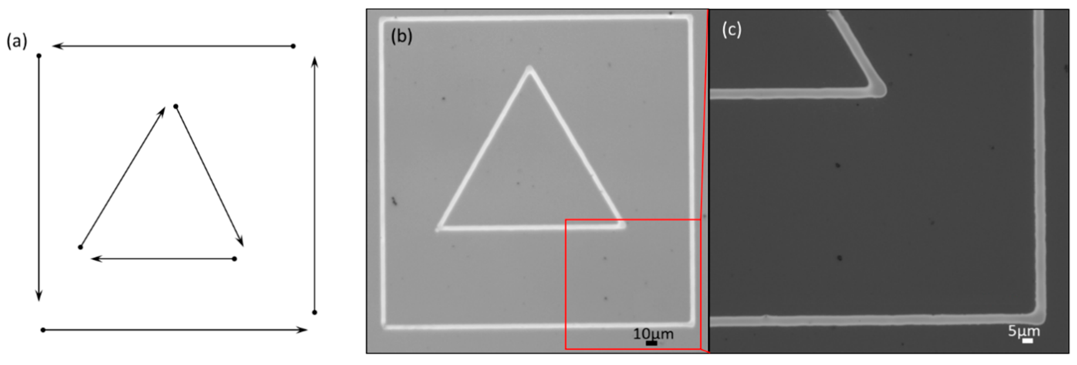
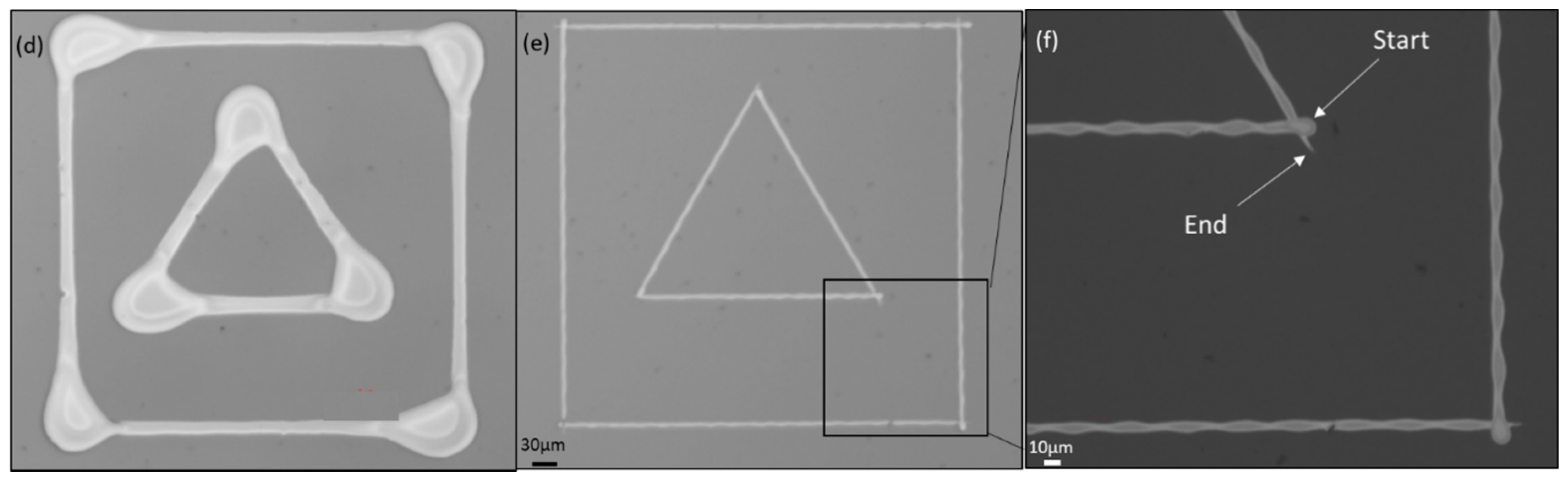
To demonstrate our proposed method, we used 2D patterns with the pattern size of (0.5 mm × 0.5 mm), as shown in Figure 15a. In the case of printing by using the conventional constant jetting frequency approach, the printing speed was set to be as low as 0.05 mm/s to minimize the end point effects, as shown in Figure 15b. Figure 15c shows the magnified image of the printed results, and no end point effects can be found. However, if the printing speed is too low, it is not efficient, because it will take considerable time to print the desired pattern. To increase the printing speed, the frequency also needs to be increased accordingly. Figure 15d shows the printed results using the conventional constant frequency jetting of 1750 Hz with target printing speed of 52.5 mm/s. Here, the acceleration and deceleration are set to 1 m/s2. However, considering the acceleration and deceleration, when printing the lines with length less than 0.5 mm, the printing speed cannot reach the target speed, which means the printing speed varies throughout the printing process. Figure 15d shows that in the case of using conventional methods, a large amount of overlapping droplets are deposited at the end points of jetting.
However, Figure 15e,f shows that in the case of printing using encoder sensors signals, there is no significant overlapping at the end points of the patterns, in spite of the high printing speed of 52.5 mm/s. In this experiment, a sufficient dummy length of 3 mm was used, so that printing speed would be constant at 52.5 mm/s throughout line printing. Note that 30 μm offset of printing location is considered to compensate for the possible shift in the printing location. Note also that in Figure 15f, the start point and the end point show a slight difference in shape, due to the equivalent DC voltage behavior, as discussed in Figure 12. Nonetheless, when the printing speed is increased to more than 52.5 mm/s, the printed results in Figure 15e,f show reasonable uniformity of printed line. Here, trigger signals are generated at each distance of 30 μm to print lines, and the corresponding jet frequency would be 1750 Hz. Note that in the case of higher frequency than 1.5 kHz, the equivalent DC voltage effects dominate the pulse voltage effects. As a result, the line can be connected by trigger signal based on a relatively large dot distance of 30 μm. For better understanding, kindly refer to the video in Ref. [10].
4. Conclusions
In conventional EHD vector printing based on constant frequency jetting, to print uniform line pattern, the printing speed should be no more than 1 mm/s.
To increase the printing speed for EHD vector printing, we proposed a vector printing method using encoder sensor signals from two axes to generate trigger signals for jetting at each pre-set distance. To implement the method, we developed the so-called encoder processing unit (EPU) module, which is capable of changing various jetting parameters, such as dot spacing, the dummy distance, and the printing mode via printing software. By using the EPU, trigger pulses for jetting can be generated based on pre-set spacing distance, irrespective of the printing speed. By using the EPU, the printing speed can be increased by more than 10 mm/s without affecting the deposition amount in the end points.
However, in the case of increasing the printing speed further, there are two uniformity issues at both ends: dot size (or deposition amount) variance and offset position in the printing direction. The main reason for slight dot size deviation of the first few droplets is that the jetting amount is related to the jet frequency. The jet frequency in the acceleration and deceleration regions is much lower than in the constant target speed region. As a result, the droplet amount is likely to be smaller than in the other region.
To reduce the dot size variation, we implemented an additional counting function in the EPU, so that the acceleration and deceleration region can be excluded for printing. Nevertheless, in the case of using high jetting frequency, there were persistent printing uniformity problems at the end point, because the equivalent DC voltage due to pulse voltage dominated the pulse voltage. The equivalent DC voltage at the initial printing part is slightly lower than at the rest of the printing region. As a result, the equivalent DC voltage can shift the starting printing positon of lines in the printing direction. Another possible reason for the printed line offset is due to fast moving of the printing substrate relative to the nozzle, because the target positon can be moved to the moving direction, before the jet is deposited on the substrate. The shift in printing can result in disconnection in lines, if connected lines are needed. So, we proposed the use of a position offset compensation method in the case of high-speed application and showed successful implementation in the case of a printing speed of 50 mm/s.
As a result of our proposed methods, uniform patterns could be printed in arbitrary printing direction for patterning with a printing speed of more than 50 mm/s, which is significantly higher than the conventional printing speed of less than 1 mm/s.
Supplementary Materials
The following are available online at https://www.mdpi.com/2076-3417/8/3/351/s1, Video S1: Vector Printing Method for High-Speed Electrohydrodynamic (EHD) Jet Printing Based on Encoder Position Sensors.
Acknowledgments
This research was supported by the Basic Science Research Program through the National Research Foundation of Korea (NRF), funded by the Ministry of Education (2016R1D1A1B01006801), and partially supported by the Soonchunhyang University Research Fund.
Author Contributions
Kye-Si Kwon created an initial idea of EPU to print uniform patterns near the end points of lines; and he guided Thanh Huy Phung and Luu Ngoc Nguyen to carry out experiment and development. Thanh Huy Phung wrote the manuscript with help of Kye-Si Kwon.
Conflicts of Interest
The authors declare no conflict of interest.
References
- Onses, M.S.; Sutanto, E.; Ferreira, P.M.; Alleyne, A.G.; Rogers, J.A. Mechanisms, Capabilities, and Applications of High-Resolution Electrohydrodynamic Jet Printing. Small 2015, 11, 4237–4266. [Google Scholar] [CrossRef] [PubMed]
- Jaworek, A.; Krupa, A. Classification of the modes of EHD spraying. J. Aerosol. Sci. 1999, 30, 873–893. [Google Scholar] [CrossRef]
- Lee, A.; Jin, H.; Dang, H.W.; Choi, K.H.; Ahn, K.H. Optimization of experimental parameters to determine the jetting regimes in electrohydrodynamic printing. Langmuir 2013, 29, 13630–13639. [Google Scholar] [CrossRef] [PubMed]
- Mishra, S.; Barton, K.L.; Alleyne, A.G.; Ferreira, P.M.; Rogers, J.A. High-speed and drop-on-demand printing with a pulsed electrohydrodynamic jet. J. Micromech. Microeng. 2010, 20, 095026. [Google Scholar] [CrossRef]
- Barton, K.; Mishra, S.; Alleyne, A.; Ferreira, P.; Rogers, J. Control of high-resolution electrohydrodynamic jet printing. Control Eng. Pract. 2011, 19, 1266–1273. [Google Scholar] [CrossRef]
- Kwon, K.S.; Lee, D.Y. Investigation of pulse voltage shape effects on electrohydrodynamic jets using a vision measurement technique. J. Micromech. Microeng. 2013, 23, 065018. [Google Scholar] [CrossRef]
- Park, J.; Hwang, J. Fabrication of a flexible Ag-grid transparent electrode using ac based electrohydrodynamic jet printing. J. Phys. D 2014, 47, 405102. [Google Scholar] [CrossRef]
- Phung, T.H.; Kim, S.; Kwon, K.S. A high speed electrohydrodynamic (EHD) jet printing method for line printing. J. Micromech. Microeng. 2017, 27, 095003. [Google Scholar] [CrossRef]
- Schneider, J.; Rohner, P.; Thureja, D.; Schmid, M.; Galliker, P.; Poulikakos, D. Electrohydrodynamic nanodrip printing of high aspect ratio metal grid transparent electrodes. Adv. Funct. Mater. 2016, 26, 833–840. [Google Scholar] [CrossRef]
- Kwon, K.S. EHD Vector Printing Method by Using Encoder Signals. 2018. Available online: https://youtu.be/sgiqz0djV8M (accessed on 11 February 2018).
Figure 1.
Schematics of the EHD printing systems. (a) The conventional EHD jet system without synchronization with respect to position information, and (b) the proposed EHD jet system with position synchronization.
Figure 1.
Schematics of the EHD printing systems. (a) The conventional EHD jet system without synchronization with respect to position information, and (b) the proposed EHD jet system with position synchronization.

Figure 2.
Non-uniform jetting due to printing speed variation.
Figure 3.
Non-uniform effect of vector printing on printed patterns. (a) Printing speed effects on dot size; (b) typcial printed lines using a printing speed of 30 mm/s.
Figure 3.
Non-uniform effect of vector printing on printed patterns. (a) Printing speed effects on dot size; (b) typcial printed lines using a printing speed of 30 mm/s.

Figure 4.
EPU prototype. (a) Front panel; (b) back panel; and (c) encoder wiring configuration.
Figure 5.
Vector printing using equally spaced distance. (a) Vector movement of 2 axes, and (b) equally spaced distance for vector printing.
Figure 5.
Vector printing using equally spaced distance. (a) Vector movement of 2 axes, and (b) equally spaced distance for vector printing.
Figure 6.
Pulse voltage generation based on two encoder signals.

Figure 7.
Jetting frequency effects using the EPU according to printing speed.

Figure 8.
Vector printing using pre-set dummy distance. (a) Vector movement considering dummy distance; (b) jetting region according to pre-set dummy distance method; and (c) printing sequence using dummy length, an example of printing a square.
Figure 8.
Vector printing using pre-set dummy distance. (a) Vector movement considering dummy distance; (b) jetting region according to pre-set dummy distance method; and (c) printing sequence using dummy length, an example of printing a square.

Figure 9.
Built-in CAD software that is used to implement the EPU function (Supplementary Video, Ref. [10]).
Figure 9.
Built-in CAD software that is used to implement the EPU function (Supplementary Video, Ref. [10]).

Figure 10.
Flow chart for printing CAD-based line printing using the EPU.

Figure 11.
Jetting behavior due to different printing modes (a) Printing using conventional constant frequency jetting; (b) printing using the EPU including acceleration and deceleration; (c) printing using the EPU excluding acceleration and deceleration by using the dummy part.
Figure 11.
Jetting behavior due to different printing modes (a) Printing using conventional constant frequency jetting; (b) printing using the EPU including acceleration and deceleration; (c) printing using the EPU excluding acceleration and deceleration by using the dummy part.
Figure 12.
Line printing using the dummy distance (d1, d2 = 3 mm) function of the EPU with ds = 20 µm.
Figure 12.
Line printing using the dummy distance (d1, d2 = 3 mm) function of the EPU with ds = 20 µm.

Figure 13.
Effect of transient equivalent DC voltage.

Figure 14.
Offset compensation.
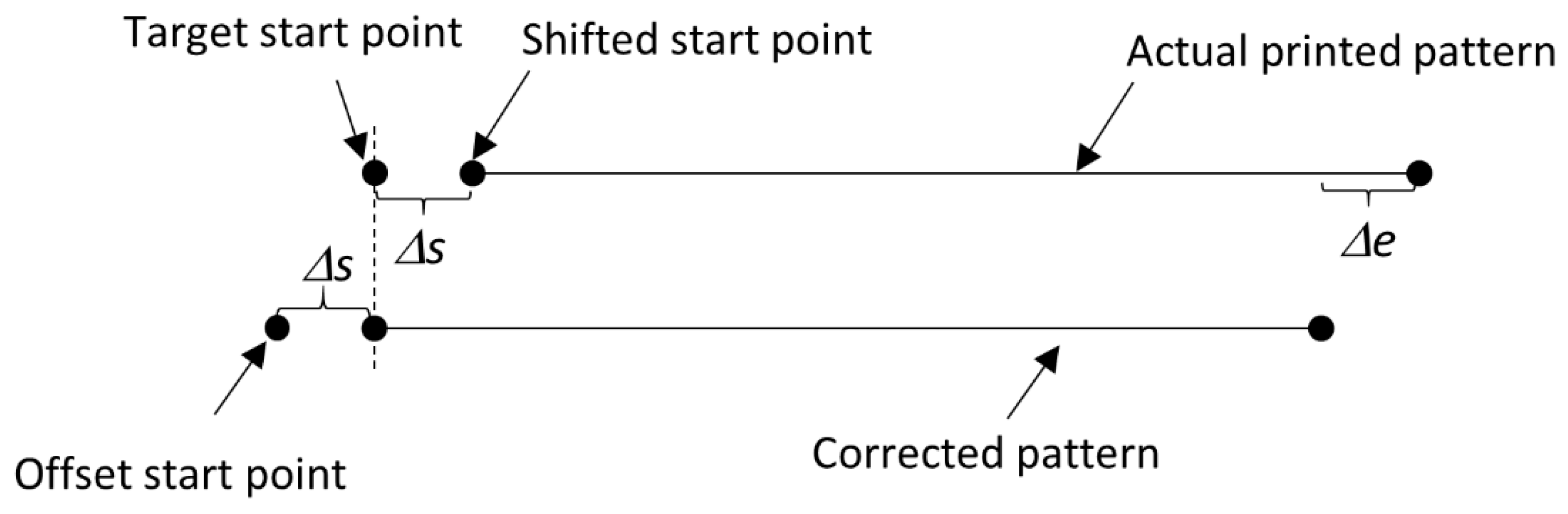
Figure 15.
2D patterning with arbitrary printing directions (Supplementary Video, Ref. [10]). (a) Different printing directions for testing; (b) printing using the conventional constant jetting frequency method using jetting frequency of 10 Hz and low speed of 0.05 mm/s; (c) magnified printing result of (b); (d) printing at high frequency of 1750 Hz and target speed of 52.5 mm/s using the conventional constant frequency; (e) printing using the proposed equal spaced triggering of 30 μm and printing speed of 52.5 mm/s, with dummy lengths of 3 mm; and (f) magnified printing result of (e).


Table 1.
EPU specification.
| Droplet spacing | From (1 to 64) encoder pulses. |
| Dummy length | Dummy length + Printing length < 262,144 pulses. |
| Printing pattern length | |
| Encoder input signal bandwidth | 10 MHz |
© 2018 by the authors. Licensee MDPI, Basel, Switzerland. This article is an open access article distributed under the terms and conditions of the Creative Commons Attribution (CC BY) license (http://creativecommons.org/licenses/by/4.0/).
Share and Cite
MDPI and ACS Style
Phung, T.H.; Nguyen, L.N.; Kwon, K.-S. A Vector Printing Method for High-Speed Electrohydrodynamic (EHD) Jet Printing Based on Encoder Position Sensors. Appl. Sci. 2018, 8, 351. https://doi.org/10.3390/app8030351
AMA Style
Phung TH, Nguyen LN, Kwon K-S. A Vector Printing Method for High-Speed Electrohydrodynamic (EHD) Jet Printing Based on Encoder Position Sensors. Applied Sciences. 2018; 8(3):351. https://doi.org/10.3390/app8030351
Chicago/Turabian StylePhung, Thanh Huy, Luu Ngoc Nguyen, and Kye-Si Kwon. 2018. "A Vector Printing Method for High-Speed Electrohydrodynamic (EHD) Jet Printing Based on Encoder Position Sensors" Applied Sciences 8, no. 3: 351. https://doi.org/10.3390/app8030351
Note that from the first issue of 2016, this journal uses article numbers instead of page numbers. See further details here.