Improving the Electrochemical Performance of LiNi0.80Co0.15Al0.05O2 in Lithium Ion Batteries by LiAlO2 Surface Modification

 ,
,
Abstract
:Featured Application
Abstract
1. Introduction
- (i.)
- Controlling the residual lithium compound content by reducing the proportion of lithium salt or by extending the time of the solid phase reaction at high temperature.
- (ii.)
- Washing the cathode materials several times in water, carbonate, organic acids, or organic solvents.
- (iii.)
- Enhancing the capacity and electronic conductivity by coating the electroactive materials; TiO2, AlF3, Al2O3, SiO2, and AlPO4 have been suggested as suitable coating materials for the layered cathodes [7,8,9,10,11,12,13,14,15,16]. The coating material mainly acts as an isolation layer to prevent side reactions and reduce the pH, which improved thermal stability and cycling stability of the cathode materials.
2. Experiment
2.1. Synthesis of NCA
2.2. LiAlO2 Modified NCA
2.3. Material Characterizations
2.4. Electrochemical Measurement
3. Results and Discussion
4. Conclusions
Supplementary Materials
Acknowledgments
Author Contributions
Conflicts of Interest
References
- Zhou, P.; Zhang, Z.; Meng, H.; Lu, Y.; Cao, J.; Cheng, F.; Tao, Z.; Chen, J. SiO2-coated LiNi0.915Co0.075Al0.01O2 cathode material for rechargeable Li-ion batteries. Nanoscale 2016, 8, 19263–19269. [Google Scholar] [CrossRef] [PubMed]
- Xu, Y.; Li, X.; Wang, Z.; Guo, H.; Huang, B. Structure and electrochemical performance of TiO2-coated LiNi0.80Co0.15Al0.05O2 cathode material. Mater. Lett. 2015, 143, 151–154. [Google Scholar] [CrossRef]
- Ruan, Z.; Zhu, Y.; Teng, X. Effect of pre-thermal treatment on the lithium storage performance of LiNi0.8Co0.15Al0.05O2. J. Mater. Sci. 2016, 51, 1400–1408. [Google Scholar] [CrossRef]
- Kleiner, K.; Melke, J.; Merz, M.; Jakes, P.; Nagel, P.; Schuppler, S.; Liebau, V.; Ehrenberg, H. Unraveling the Degradation Process of LiNi0.8Co0.15Al0.05O2 Electrodes in Commercial Lithium Ion Batteries by Electronic Structure Investigations. ACS Appl. Mater. Interfaces 2015, 7, 19589–19600. [Google Scholar] [CrossRef] [PubMed]
- Watanabe, S.; Kinoshita, M.; Hosokawa, T.; Morigaki, K.; Nakura, K. Capacity fade of LiAlyNi1−x−yCoxO2 cathode for lithium-ion batteries during accelerated calendar and cycle life tests (surface analysis of LiAlyNi1−x−yCoxO2 cathode after cycle tests in restricted depth of discharge ranges). J. Power Sources 2014, 258, 210–217. [Google Scholar] [CrossRef]
- Yoon, S.H.; Lee, C.W.; Bae, Y.S.; Hwang, I.Y.; Park, Y.K.; Song, J.H. Method of Preparation for Particle Growth Enhancement of LiNi0.8Co0.15Al0.05O2. Electrochem. Solid-State Lett. 2009, 12, A211–A214. [Google Scholar] [CrossRef]
- Dai, G.; Yu, M.; Shen, F.; Cao, J.; Ni, L.; Chen, Y.; Tang, Y. Improved cycling performance of LiNi0.8Co0.15Al0.05O2/Al2O3 with core-shell structure synthesized by a heterogeneous nucleation-and-growth process. Ionics 2016, 22, 2021–2026. [Google Scholar] [CrossRef]
- Nurpeissova, A.; Choi, M.H.; Kim, J.S.; Myung, S.K.; Kim, S.S.; Sun, Y.K. Effect of titanium addition as nickel oxide formation inhibitor in nickel-rich cathode material for lithium-ion batteries. J. Power Sources 2015, 299, 425–433. [Google Scholar] [CrossRef]
- Zhang, L.; Luo, F.; Wang, J.; Guo, Y. Surface Coating and Electrochemical Properties of LiNi0.8Co0.15Al0.05O2 Cathode in Lithium-Ion Cells. Adv. Mater. Res. 2014, 1058, 317–320. [Google Scholar] [CrossRef]
- Zhu, L.; Liu, Y.; Wu, W.; Wu, X.; Tang, W.; Wu, Y. Surface fluorinated LiNi0.8Co0.15Al0.05O2 as a positive electrode material for lithium ion batteries. J. Mater. Chem. A 2015, 3, 15156–15162. [Google Scholar] [CrossRef]
- Li, X.; Xie, Z.; Liu, W.; Ge, W.; Wang, H.; Qu, M. Effects of fluorine doping on structure, surface chemistry, and electrochemical performance of LiNi0.8Co0.15Al0.05O2. Electrochim. Acta 2015, 174, 1122–1130. [Google Scholar] [CrossRef]
- Li, L.; Chen, Z.; Zhang, Q.; Xu, M.; Zhou, X.; Zhu, H.; Zhang, K. A hydrolysis-hydrothermal route for the synthesis of ultrathin LiAlO2-inlaid LiNi0.5Co0.2Mn0.3O2 as a high-performance cathode material for lithium ion batteries. J. Mater. Chem. A 2015, 3, 894–904. [Google Scholar] [CrossRef]
- Qin, C.; Cao, J.; Chen, J.; Dai, G.; Wu, T.; Chen, Y.; Tang, Y.; Li, A.; Chen, Y. Improvement of electrochemical performance of nickel rich LiNi0.6Co0.2Mn0.2O2 cathode active material by ultrathin TiO2 coating. Dalton Trans. 2016, 45, 9669–9675. [Google Scholar] [CrossRef] [PubMed]
- Lee, M.J.; Noh, M.; Park, M.H.; Jo, M.; Kim, H.; Nam, H.; Cho, J. The role of nanoscale-range vanadium treatment in LiNi0.8Co0.15Al0.05O2 cathode materials for Li-ion batteries at elevated temperatures. J. Mater. Chem. A 2015, 3, 13453–13460. [Google Scholar] [CrossRef]
- Tran, H.Y.; Tӓubert, C.; Fleischhammer, M.; Axmann, P.; Küppers, L.; Wohlfahrt-Mehrens, M. LiMn2O4Spinel/LiNi0.8Co0.15Al0.05O2 Blends as Cathode Materials for Lithium-Ion Batteries. J. Electrochem. Soc. 2011, 158, A556–A561. [Google Scholar] [CrossRef]
- Cho, Y.; Cho, J. Significant Improvement of LiNi0.8Co0.15Al0.05O2 Cathodes at 60 °C by SiO2 Dry Coating for Li-Ion Batteries. J. Electrochem. Soc. 2010, 157, A625–A629. [Google Scholar] [CrossRef]
- Chen, Y.; Li, P.; Zhao, S.; Zhuang, Y.; Zhao, S.; Zhou, Q.; Zheng, J. Influence of integrated microstructure on the performance of LiNi0.8Co0.15Al0.05O2 as a cathodic material for lithium ion batteries. RSC Adv. 2017, 7, 29233–29239. [Google Scholar] [CrossRef]
- Wu, F.; Wang, M.; Su, W.; Chen, S.; Xu, B. Effect of TiO2-coating on the electrochemical performances of LiCo1/3Ni1/3Mn1/3O2. J. Power Sources 2009, 191, 628–632. [Google Scholar] [CrossRef]
- Lee, D.J.; Scrosati, B.; Sun, Y.K. Ni3(PO4)2-coated Li[Ni0.8Co0.15Al0.05]O2 lithium battery electrode with improved cycling performance at 55 °C. J. Power Sources 2011, 196, 7742–7746. [Google Scholar] [CrossRef]
- Aurbach, D.; Levi, M.D.; Levi, E.; Teller, H.; Markovsky, B.; Salitra, G.; Heider, U.; Heider, L. Common Electroanalytical Behavior of Li Intercalation Processes into Graphite and Transition Metal Oxides. J. Electrochem. Soc. 1988, 145, 3024–3034. [Google Scholar] [CrossRef]
- Bai, Y.; Wang, X.; Zhang, X.; Shu, H.; Yang, X.; Hu, B.; Wei, Q.; Wu, H.; Song, Y. The kinetics of Li-ion deintercalation in the Li-rich layered Li1.12[Ni0.5Co0.2Mn0.3]0.89O2 studied by electrochemical impedance spectroscopy and galvanostatic intermittent titration technique. Electrochim. Acta 2013, 109, 355–364. [Google Scholar] [CrossRef]
- Liu, T.; Garsuch, A.; Chesneau, F.; Lucht, B.L. Surface phenomena of high energy Li(Ni1/3Co1/3Mn1/3)O2/graphite cells at high temperature and high cutoff voltages. J. Power Sources 2014, 269, 920–926. [Google Scholar] [CrossRef]


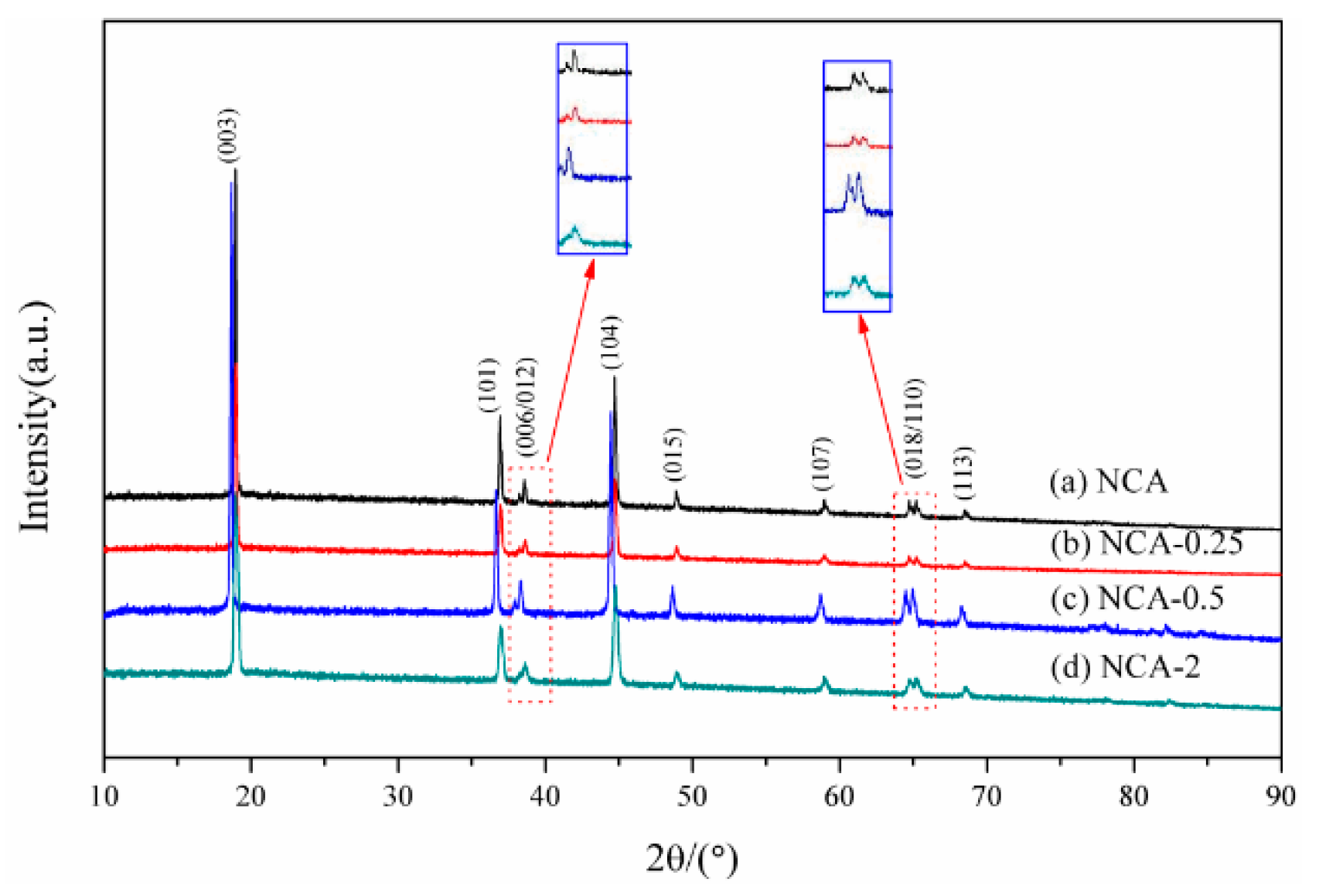
| Sample | a (±0.0003 Å) | c (±0.0004 Å) | c/a | I003/I104 |
|---|---|---|---|---|
| NCA | 2.8576 | 14.0508 | 4.92 | 2.35 |
| NCA-0.25 | 2.8601 | 14.0340 | 4.91 | 2.19 |
| NCA-0.5 | 2.8677 | 14.2335 | 4.96 | 1.90 |
| NCA-2 | 2.8648 | 14.0131 | 4.89 | 2.31 |
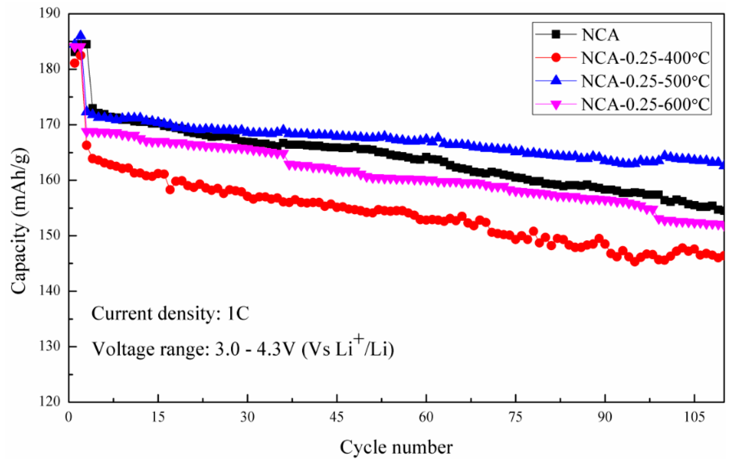
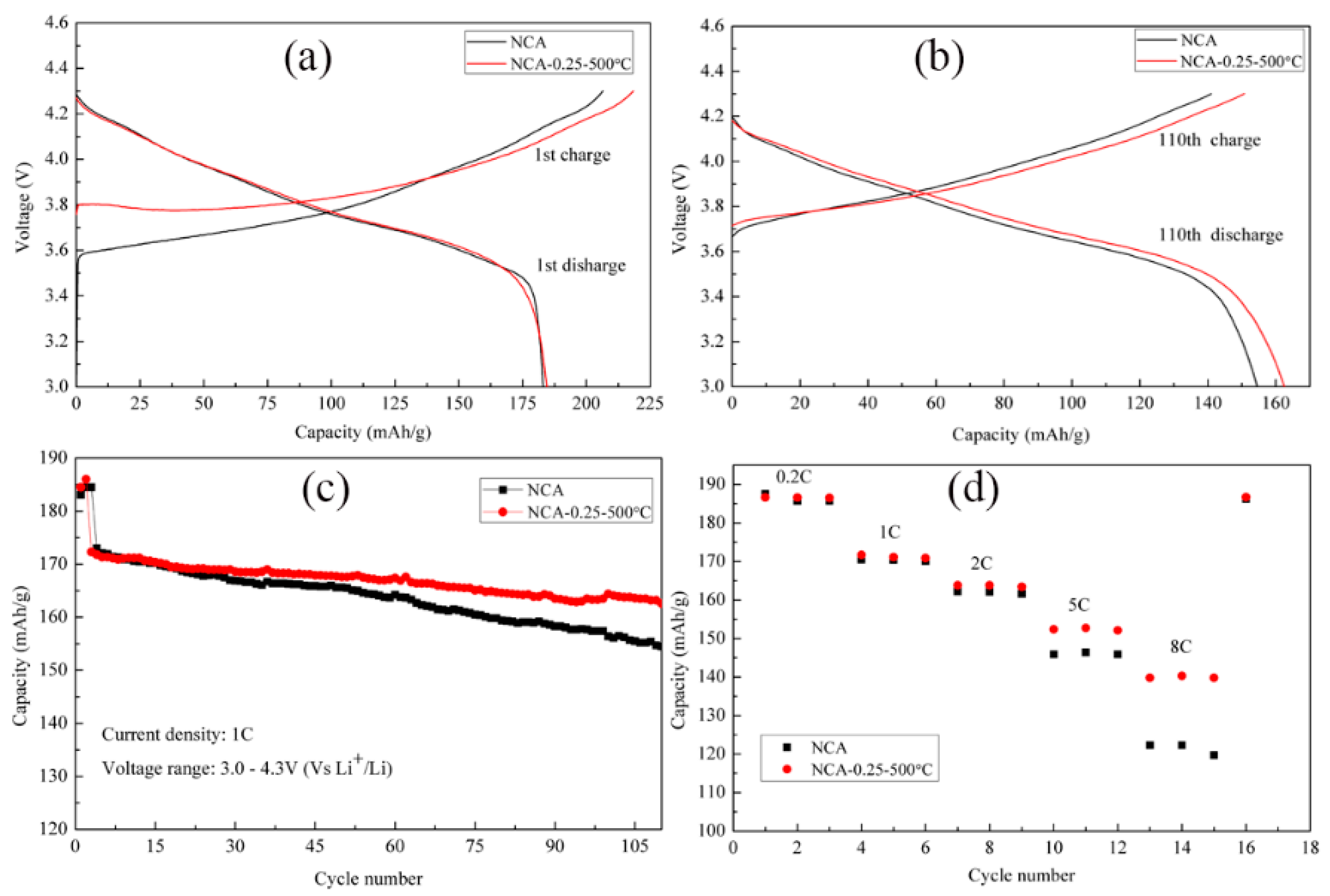
| Sample | pH | Residual Alkaline (Li2CO3% + LiOH%) | First Discharge Capacity at 0.2 C (mAh/g) | First Discharge Efficiency (%) | Discharge Capacity at 1 C (mAh/g) | 110 Cycles Capacity Retention (%) |
|---|---|---|---|---|---|---|
| NCA | 12.70 | 3.99% | 183.1 | 88.6% | 173.0 | 89.31% |
| NCA-0.25-400 °C | 11.86 | 1.78% | 181.1 | 83.1% | 166.3 | 88.03% |
| NCA-0.25-500 °C | 11.80 | 1.48% | 184.5 | 83.8% | 172.3 | 94.67% |
| NCA-0.25-600 °C | 11.82 | 1.38% | 184.1 | 84.3% | 168.6 | 92.88% |
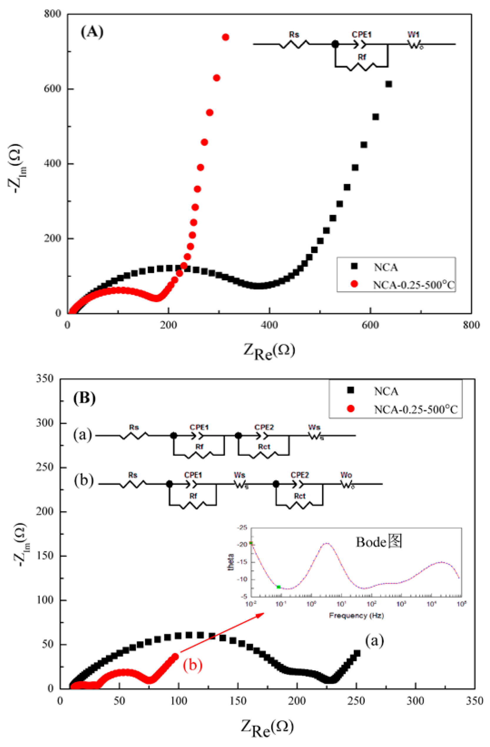
| Sample | Original | After 25 Cycles | ||||||
|---|---|---|---|---|---|---|---|---|
| Rs | Rf | Wo | Rs | Rct | Rf | Ws | Wo | |
| NCA | 8.28 | 327.01 | 372.60 | 9.16 | 200.20 | 13.62 | 160.90 | ----- |
| NCA-0.25 | 8.71 | 159.70 | 82.43 | 9.93 | 9.54 | 32.06 | 11.57 | 29.65 |
© 2018 by the authors. Licensee MDPI, Basel, Switzerland. This article is an open access article distributed under the terms and conditions of the Creative Commons Attribution (CC BY) license (http://creativecommons.org/licenses/by/4.0/).
Share and Cite
Song, C.; Wang, W.; Peng, H.; Wang, Y.; Zhao, C.; Zhang, H.; Tang, Q.; Lv, J.; Du, X.; Dou, Y. Improving the Electrochemical Performance of LiNi0.80Co0.15Al0.05O2 in Lithium Ion Batteries by LiAlO2 Surface Modification. Appl. Sci. 2018, 8, 378. https://doi.org/10.3390/app8030378
Song C, Wang W, Peng H, Wang Y, Zhao C, Zhang H, Tang Q, Lv J, Du X, Dou Y. Improving the Electrochemical Performance of LiNi0.80Co0.15Al0.05O2 in Lithium Ion Batteries by LiAlO2 Surface Modification. Applied Sciences. 2018; 8(3):378. https://doi.org/10.3390/app8030378
Chicago/Turabian StyleSong, Chunhua, Wenge Wang, Huili Peng, Ying Wang, Chenglong Zhao, Huibin Zhang, Qiwei Tang, Jinzhao Lv, Xianjun Du, and Yanmeng Dou. 2018. "Improving the Electrochemical Performance of LiNi0.80Co0.15Al0.05O2 in Lithium Ion Batteries by LiAlO2 Surface Modification" Applied Sciences 8, no. 3: 378. https://doi.org/10.3390/app8030378