Exergy Analysis of Serpentine Thermosyphon Solar Water Heater
by
Muhammad Faisal Hasan
1,2,*, 
Md. Sayeed Ur Rahim Mahadi
3,
Takahiko Miyazaki
1,4,*,
Shigeru Koyama
1,4 and
Kyaw Thu
1,2,4,* 1
Interdisciplinary Graduate School of Engineering Sciences, Kyushu University, 6–1 Kasuga-koen, Kasuga, Fukuoka 816–8580, Japan
2
Green Asia Education Center, Kyushu University, 6–1 Kasuga-koen, Kasuga, Fukuoka 816–8580, Japan
3
Institute of Energy, University of Dhaka, Dhaka 1000, Bangladesh
4
International Institute for Carbon-Neutral Energy Research, Kyushu University, Motooka, Nishi Ward, Fukuoka 819–0385, Japan
*
Authors to whom correspondence should be addressed.
Appl. Sci. 2018, 8(3), 391; https://doi.org/10.3390/app8030391
Submission received: 31 January 2018
/
Revised: 22 February 2018
/
Accepted: 1 March 2018
/
Published: 7 March 2018
(This article belongs to the Special Issue Sciences in Heat Pump and Refrigeration)
Abstract
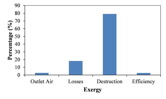
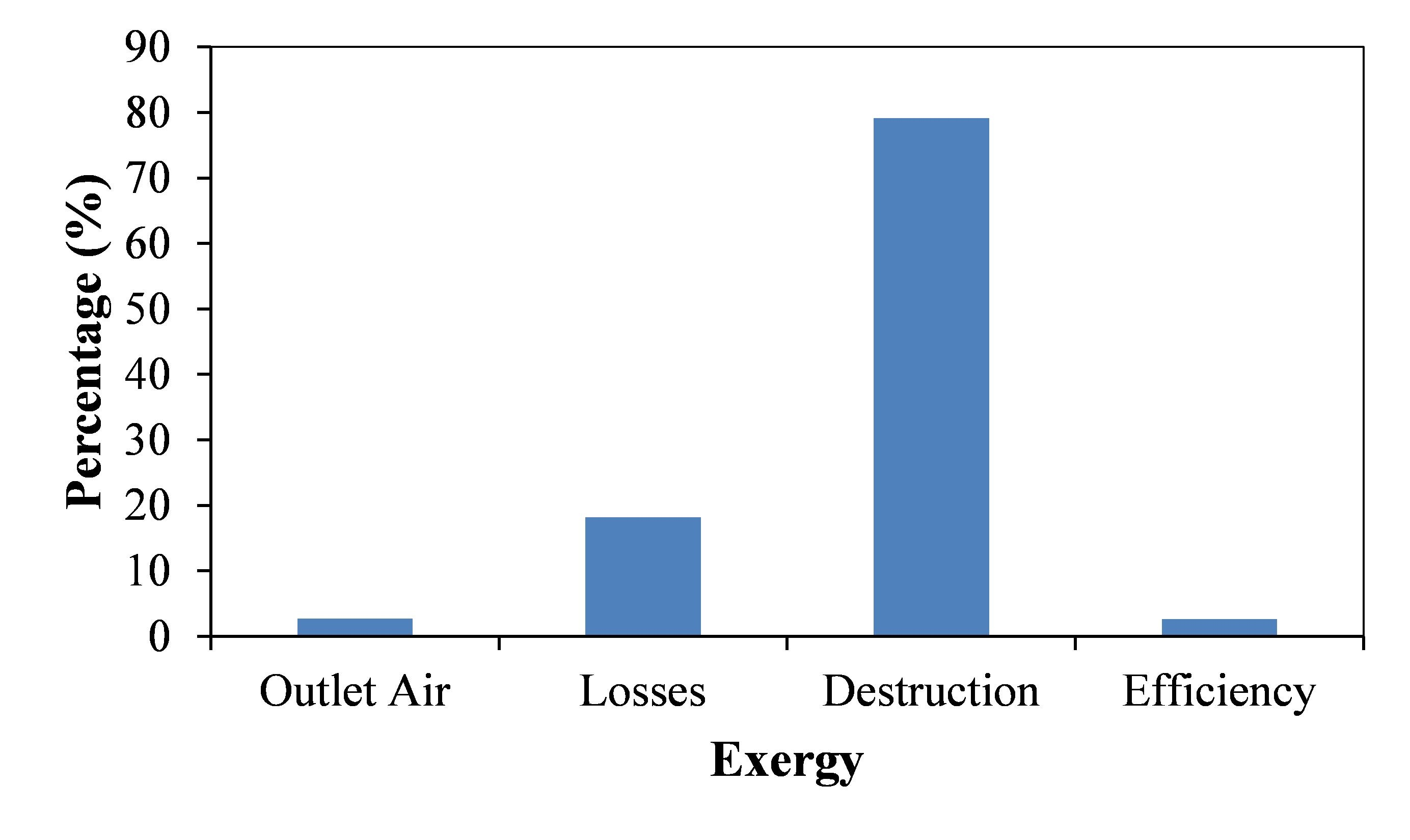
:The performance of a solar hot water system is assessed for heat pump and domestic heating applications. Thermodynamic analysis on a serpentine-type thermosyphon flat-plate solar heater is conducted using the Second Law of thermodynamics. Exergetic optimization is first performed to determine the parameters for the maximum exergy efficiency using MATLAB optimization toolbox. Geometric parameters (collector surface area, dimensions, and pipe diameter), optical parameters (transmittance absorptance product), ambient temperature, solar irradiation and operating parameters (mass flow rate, fluid temperature, and overall heat transfer (loss) coefficient) are accounted for in the optimization scheme. The exergy efficiency at optimum condition is found to be 3.72%. The results are validated using experimental data and found to be in good agreement. The analysis is further extended to the influence of various operating parameters on the exergetic efficiency. It is observed that optical and thermal exergy losses contribute almost 20%, whereas approximately 77% exergy destruction is contributed by the thermal energy conversion. Exergy destruction due to pressure drop is found negligible. The result of this analysis can be used for designing and optimization of domestic heat pump system and hot water application.
1. Introduction
Utilizing solar energy for water heating can reduce energy cost to a great extent. Serpentine type thermosyphon solar water heater (SWH) is type of passive heater that can be built easily and can be used with ease without any complexity. Such a system was constructed and tested on the premises of Dhaka University at Dhaka, Bangladesh [1]. The performance of SWH depends on several physical dimensions, operating parameters and meteorological parameters. While evaluating the performance, attention is often on the thermal efficiency only. However, the energy equation does not consider many internal and conversion loss factors. High thermal efficiency does not ensure high exergy efficiency [2,3]. Performance analysis considering exergy analysis by using the Second Law of thermodynamics can lead to the optimized performance of a system to a greater extent while tracking the entropy generation [4,5]. This paper mainly concentrates on dimensional, operating and meteorological parameter of the SWH for maximum exergy efficiency and how various parameters affect exergy efficiency.
Serpentine tube has been widely used in heat exchangers and solar water heaters for supplying heat and hot water. Physical dimensional parameters have great effect on the performance of the system. Serpentine tubes need to be carefully designed and placed in the system. A Computation Fluid Dynamics (CFD) analysis of serpentine heat exchanger showed that the optimum position lies in contact with the walls of water tank with a certain tube diameter and length [6]. Wang et al. [7] showed that the exergy efficiency varies inversely with width of the collector, using the “Three Procedure Theory” [8]. Thermal conductivity of absorber plate has significant effect on solar fraction and configuration. However, this effect can be minimized if the thermal conductivity is above 50 W/m-k [9]. Gupta et al. [10] analyzed the dependency of output exergy of air with respect to aspect ratio of collector, mass flow rate per unit absorber area and duct depth, and commented that there is an optimum inlet temperature of air and mentioned parameters for a particular system. However, they neglected the blower work during the analysis. Zhong et al. [11] provided exergy analysis model of flat plate collector (FPC) and reported 5.96% exergy efficiency where major portion of the exergy destruction is caused by energy conversion from high sun temperature to low absorber plate temperature. Luminosu et al. [12] recommended the optimum operation conditions of FPC by exergy analysis. However, they assumed constant water inlet temperature equal to ambient temperature. They did not take into account the pressure drop exergy destruction. Torres-Reyes et al. suggested FPC design method based on minimum entropy generation but they also neglected the exergy destruction due to pressure drop [13]. Farahat et al. [14] provided a detailed approach of exergy analysis and optimization of FPC and showed that the exergy efficiency is 3.898% at the optimum condition. Exergy analysis of numerous types of solar thermal collectors and processes was reviewed in detail by many researchers [15,16,17,18,19,20,21,22].
Steps for exergy balance [23] and exergetic optimization of thermosyphon SWH for dimensional and operating conditions and optimum results is shown in this paper. These steps and optimum result can be used in determining the dimensions and selecting the operating conditions for similar other systems. MATLAB optimization toolbox [24] is used to determine the parameters for the maximum exergy efficiency. The values of parameters at optimum condition are then used for examining the effect of a certain parameter on the system performance. A summary of exergy destruction and loss [14,25], dimensionless exergy [26] and exergy destruction ratio [27] is provided here, which can be used for predicting the performance of this type of systems.
2. The Serpentine Type Thermosyphon Solar Water Heater
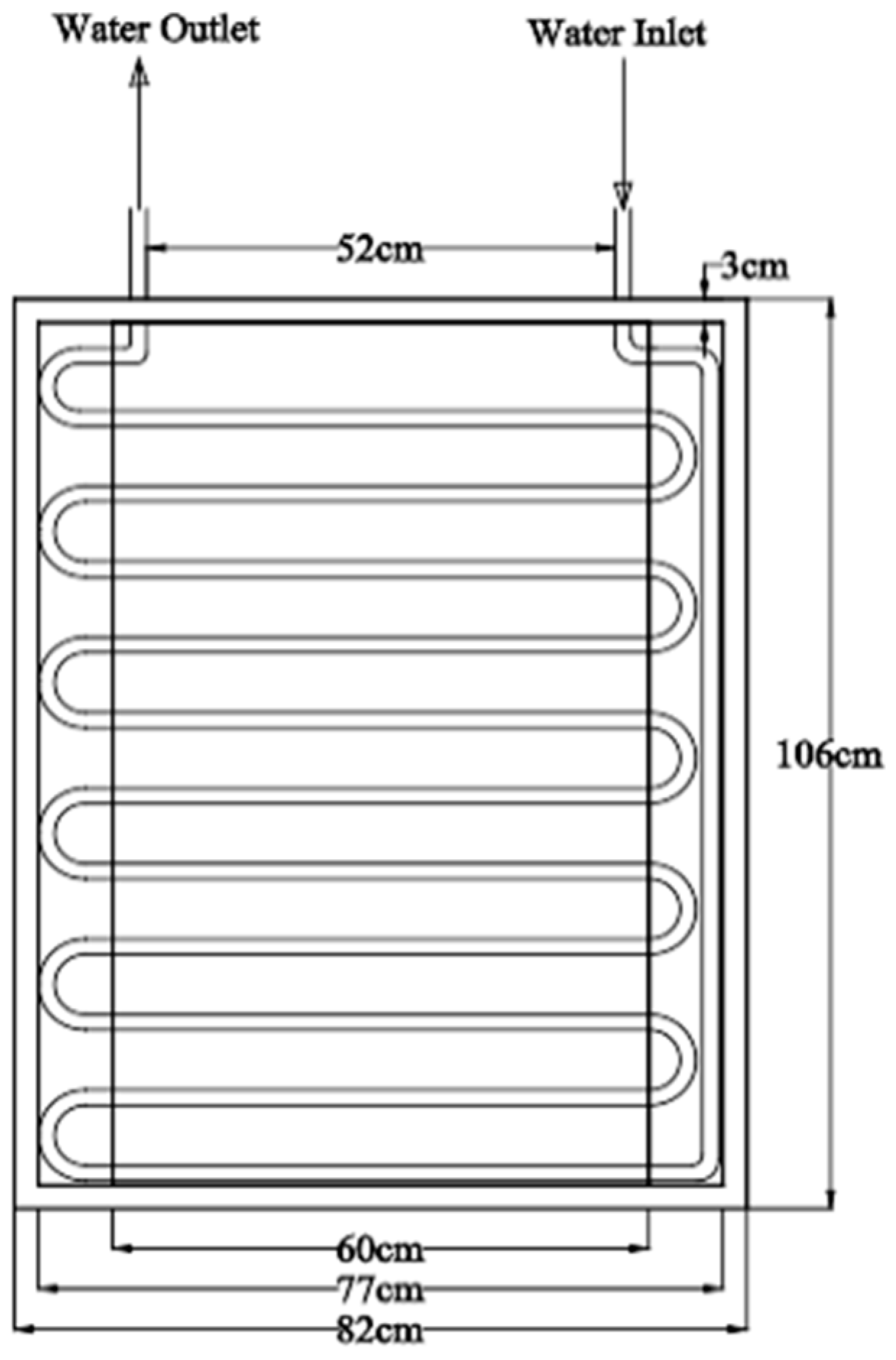
A passive flow type flat plate solar water heater has been constructed and set up on the premises of Dhaka University at Dhaka, Bangladesh (latitude 23.7° N, longitude 90.38° E) [1] as shown in Figure 1. The setup has serpentine pipes above the absorber plate which act on thermosyphon principle (Figure 1 and Figure 2). The tilt was 27° facing due south (Figure 3). Water enters the collector through the inlet pipe from the water tank and takes heat from the absorber plate. Water moves along the serpentine path toward the outlet pipe due to density variation between the hot and cold water. The major components of the SWH are as follows:
- Absorber Plate: It is a flat absorber plate coated with black paint that has high absorptance.
- Pipes: The black painted metallic pipe is placed above the absorber plate and attached to it by welding process.
- Glazing: A glass plate having high transmittance allows solar energy to pass toward absorber and reduces heat loss from the absorber plate.
- Working fluid: Water is used as the working fluid which receives heat from the absorber plate while passing through the serpentine pipe by thermosyphon action.
- Insulation: Glass wool insulation is placed behind the absorber plate to reduce the heat loss from the back side.
- Housing: It is the exterior box that contains the collector and other components.
- Water Tank: An insulated tank containing water is used to maintain the water flow to and from the collector. Density variation of water inside the tank causes the thermosyphon action.
3. Modeling of the System and Optimization
3.1. Energy Model
The basic energy balance equation of the SWH can be written as utilized energy Qu equals absorbed energy Qab minus the losses Ql:
Qab represents the energy absorbed by the FPC from the insolation after passing through the glazing. Hence, it can be written as [28]:
Various types of heat loss occur from the FPC to the surrounding through conduction, convection and radiation. Considering all the losses, the total heat loss in terms of overall heat loss coefficient Ul can be written as [29]:
Hence, Equation (1) can be written for steady state as [28]:
However, it is difficult to predict Ul and Tp simultaneously. A more convenient approach is used to write the utilized energy in terms of fluid inlet temperature to the collector by Hottel–Whillier equation [28] as:
where
The utilized energy in terms of fluid inlet and outlet temperature to and from the collector can be also written as [28]:
The thermal efficiency of the system can be written as [28]:
It is not easy to measure the mass flow rate because it is a passive (thermosyphon) system. Fluid flow occurs due to density variation, which is due to temperature variation between inlet and outlet of the absorber and also in the water tank. The mass flow rate is calculated from the energy balance equation considering absorber plate and serpentine flow path as the control volume (CV). Energy equation of the CV at steady state with zero work output is [30]:
The mass flow rate and the velocity of flow depend on each other. It is difficult to calculate both the parameters simultaneously, so it has been calculated by iterative process.
3.2. Exergy Model
The exergy input to the system comes from the exergy of the flowing fluid and the insolation. The exergy inflow from the flowing fluid is [26]:
After some simplification considering constant specific heat and using Bernoulli’s equation, it can be written as [14,25]:
The exergy input from the insolation is [26]:
However, this equation (Equation (16)) violates the Second Law of Thermodynamics for this type of systems [14]. In terms of apparent sun temperature, the corrected equation is [32]:
3.2.1. Exergy Losses
Exergy leakage due to optical loss is:
3.2.2. Exergy Destruction
Destruction of exergy occurs due to several reasons. Friction between the viscous fluid and the flow passage causes some pressure drop which accounts for some portion of exergy destruction [14].
Heat transfer from high temperature sun to the relatively low temperature absorber plate causes some entropy generation, which accounts for some portion of exergy destruction as follows [14]:
Heat transfer between the flowing fluid and absorber plate also accounts for some portion of exergy destruction which is as follow [14]:
Using Equations (11)–(19), after some mathematical simplification, the exergetic efficiency equation in terms of utilized energy can be written as [14]:
Conversely, in terms of exergy losses, it can be written as:
Dimensionless Exergy term can be written as [26]:
Exergy destruction ratio (EDR) is defined as the ratio of total exergy destruction in the system to exergy of the outlet water [27]. Mathematically,
3.3. Optimization of the System
Equation (25) represents the exergetic efficiency of the system. Optimum operating and design condition is obtained by maximizing Equation (25) for exergy efficiency subject to the constraints, i.e., Equations (4)–(9). For this, parameters such as Ta, Ts, GT, τα, , S, Cp, and ρ have been considered as constants. Aa is considered as independent parameter and others as the dependent parameters. MATLAB optimization toolbox is used for numerical optimization. Active set algorithm is used for this non-linear optimization problem. The values of some parameters used for optimization are shown in Table 1.
After optimization, following result has been obtained:
At optimum condition, the exergetic efficiency becomes: ε = 3.72%.
4. Results and Discussion
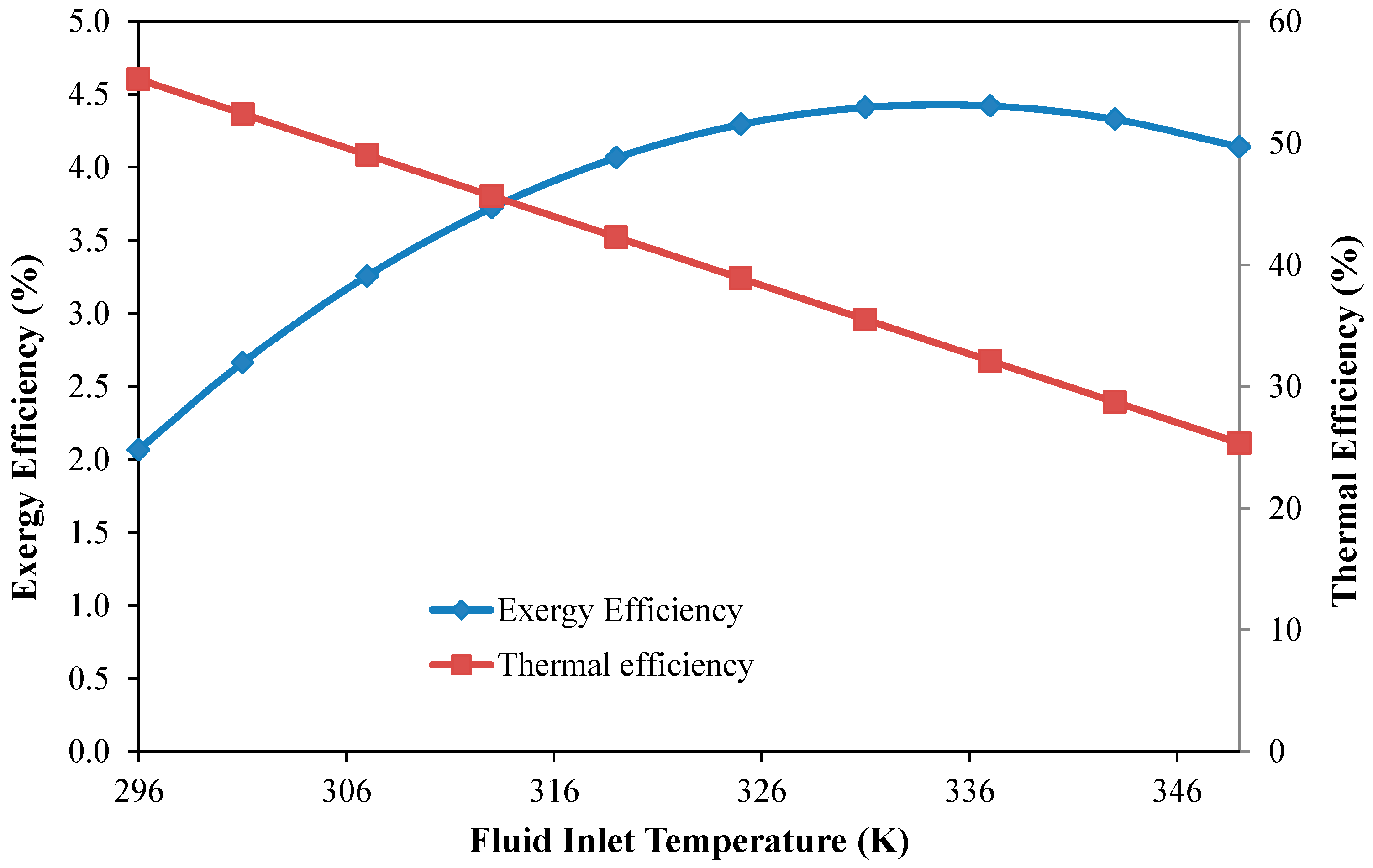
After optimization of the SHW for maximum exergy efficiency, we found 3.72% exergy efficiency. The values of parameters at optimum condition are used to examine the effect of certain parameters on the system performance. Effect of various parameters on exergy efficiency and thermal efficiency is shown in the following figures (Figure 4, Figure 5, Figure 6, Figure 7 and Figure 8). Figure 4 shows the effect of fluid inlet temperature on exergy and thermal efficiency. With the increasing fluid inlet temperature, the amount of heat transfer to the fluid (water) from the absorber plate reduces due to lesser temperature difference. Regarding the exergy efficiency, it increases with inlet temperature to the maximum value after which it reduces. Exergy efficiency depends on inlet temperature by two factors: destruction of exergy due to the temperature difference between the sun and the absorber and the exergy loss due to heat loss to the surrounding. With the increasing inlet temperature, the temperature difference between the sun and the absorber reduces, which causes lower exergy destruction. On the other hand, with the increasing inlet temperature, heat loss increases that cause higher exergy loss. In combination of exergy reduction due to the two mentioned factors, we obtain the gradual change in exergy with a maximum value at a certain point. Similar result for thermal and exergy efficiency was reported for solar collectors [9,10,14,26].
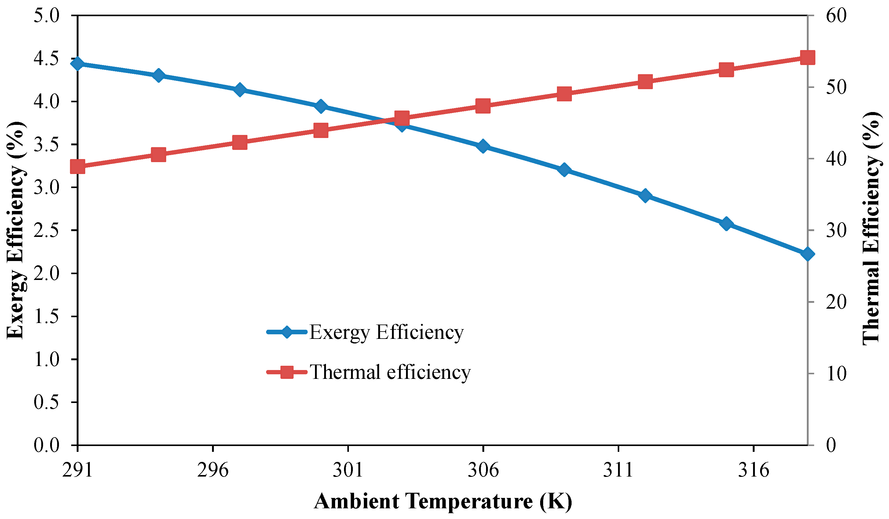
Figure 5 depicts the effect of ambient temperature on the two efficiencies. When the ambient temperature increases, the temperature difference between the absorber and the ambient reduces, which results lower heat loss. Exergy efficiency decreases significantly with the ambient temperature. As the ambient temperature increases, the amount of flow exergy reduces, for which the exergy efficiency reduces. Increasing ambient temperature from 301 K to 311 K results in an exergy efficiency drop from approximately 4% to 3%. Farahat et al. found same pattern for FPC [14].
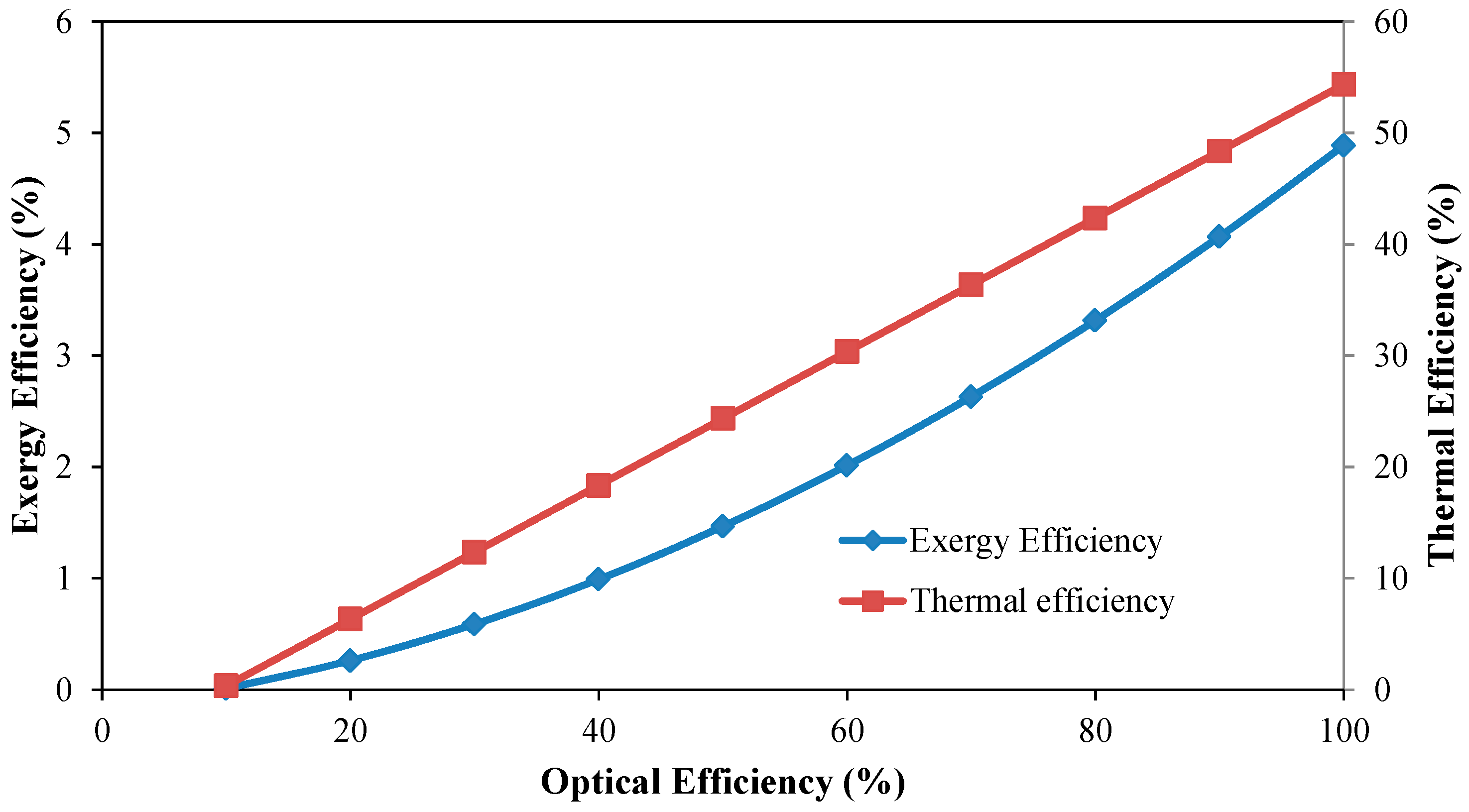
Optical losses reduce as the optical efficiency increases, hence the thermal and exergy efficiency increases (Figure 6). Increasing optical efficiency from 0% to 100% increases the exergy efficiency from 0% to 4.9%.For FPC, it was reported that the exergy efficiency increases with optical efficiency in similar manner [14].
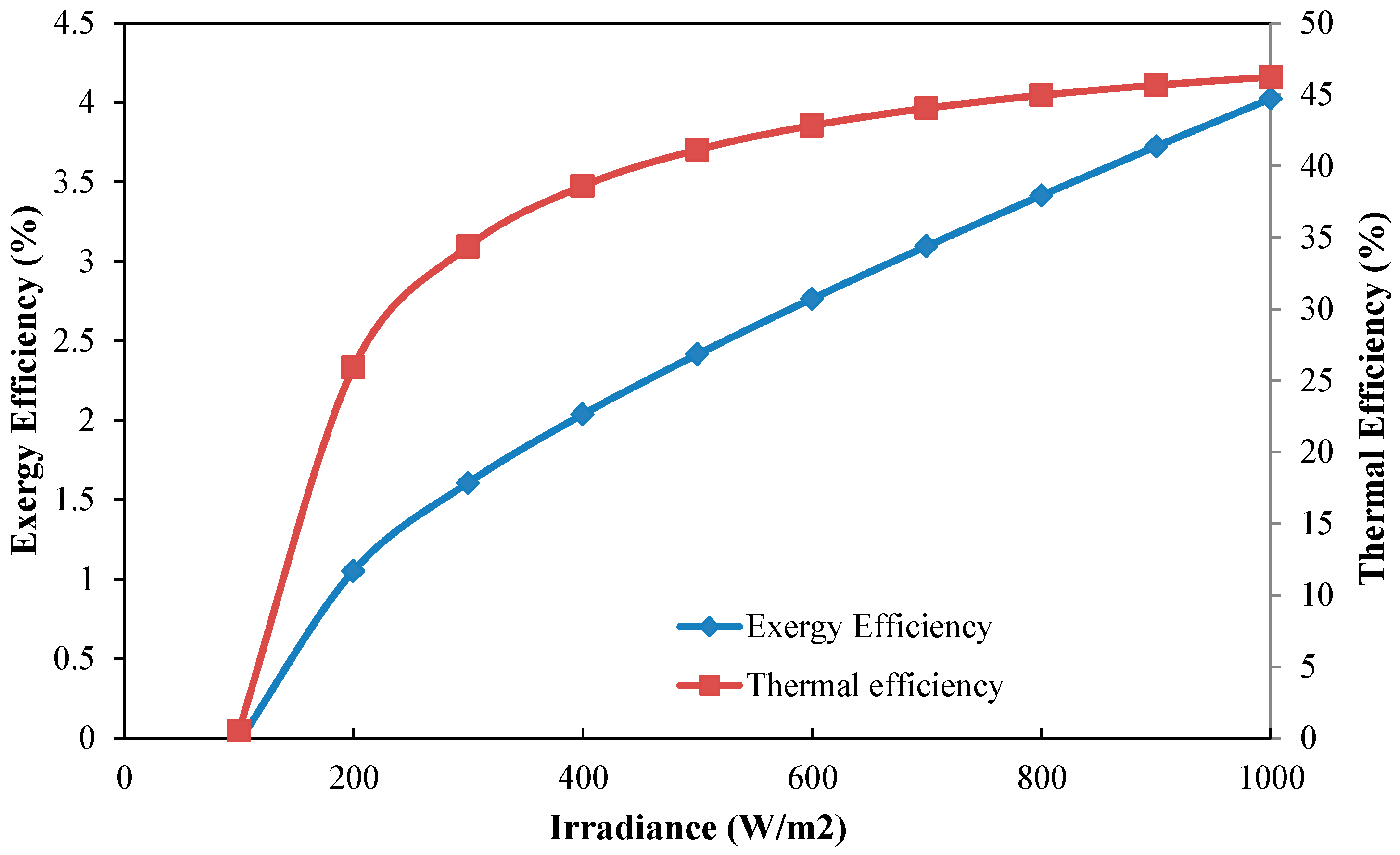
Figure 7 shows the variation of exergy and thermal efficiency with the irradiance. Exergy efficiency increases at almost steady rate between the irradiance levels 300 W/m2 to 1000 W/m2 which is similar to the result reported for FPC [14]. Thermal efficiency initially increases rapidly but later the rate of change of efficiency decreases, which reaches saturation level at around 800 W/m2 irradiance.
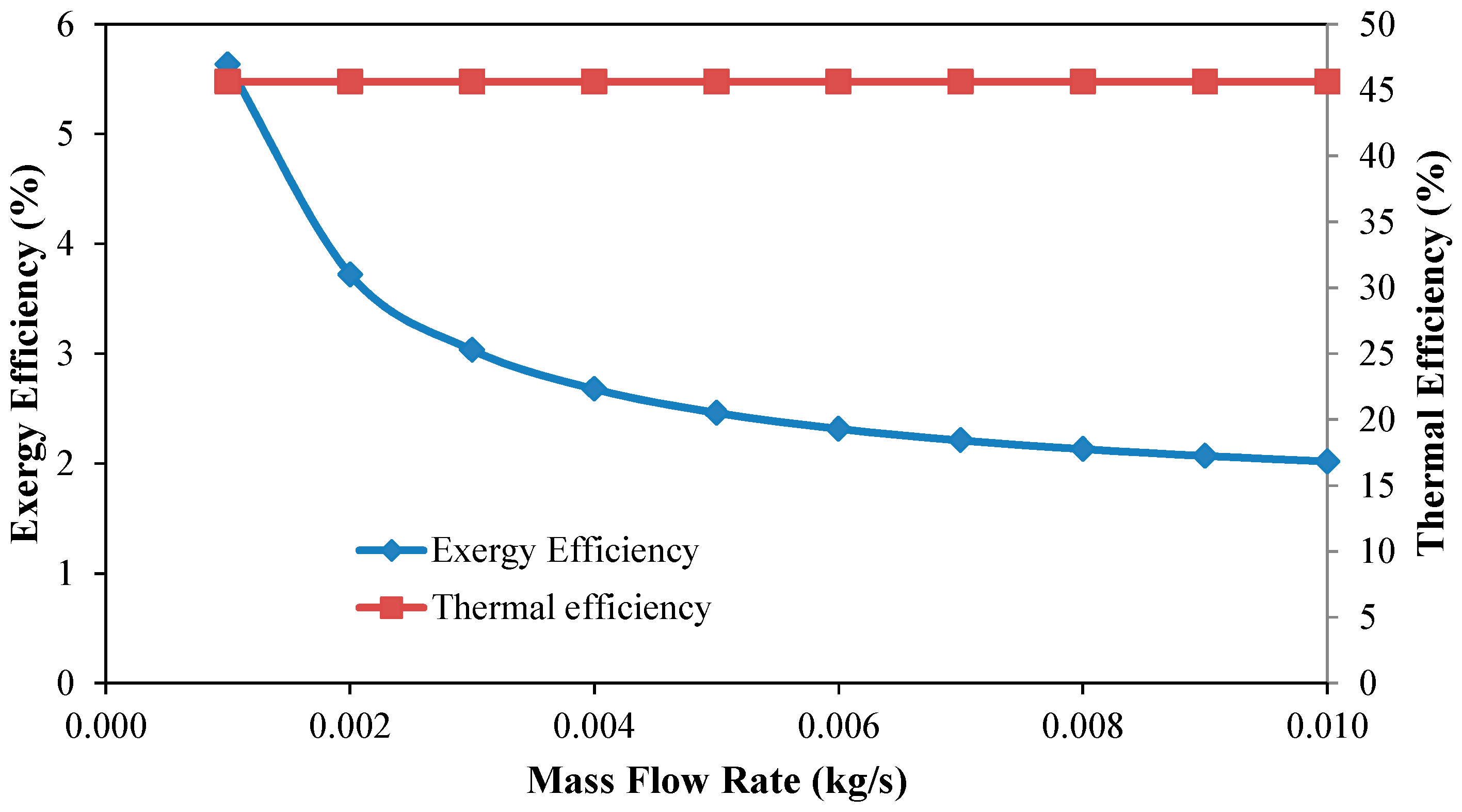
Controlling the mass flow rate in this type of passive heating system is not possible. The analysis shows that (Figure 8) the exergy efficiency decreases with the increased mass flow rate of water, while the thermal efficiency almost remains constant. A Similar pattern of exergy efficiency with respect to mass flow rate is reported by Zhong et al. [11].
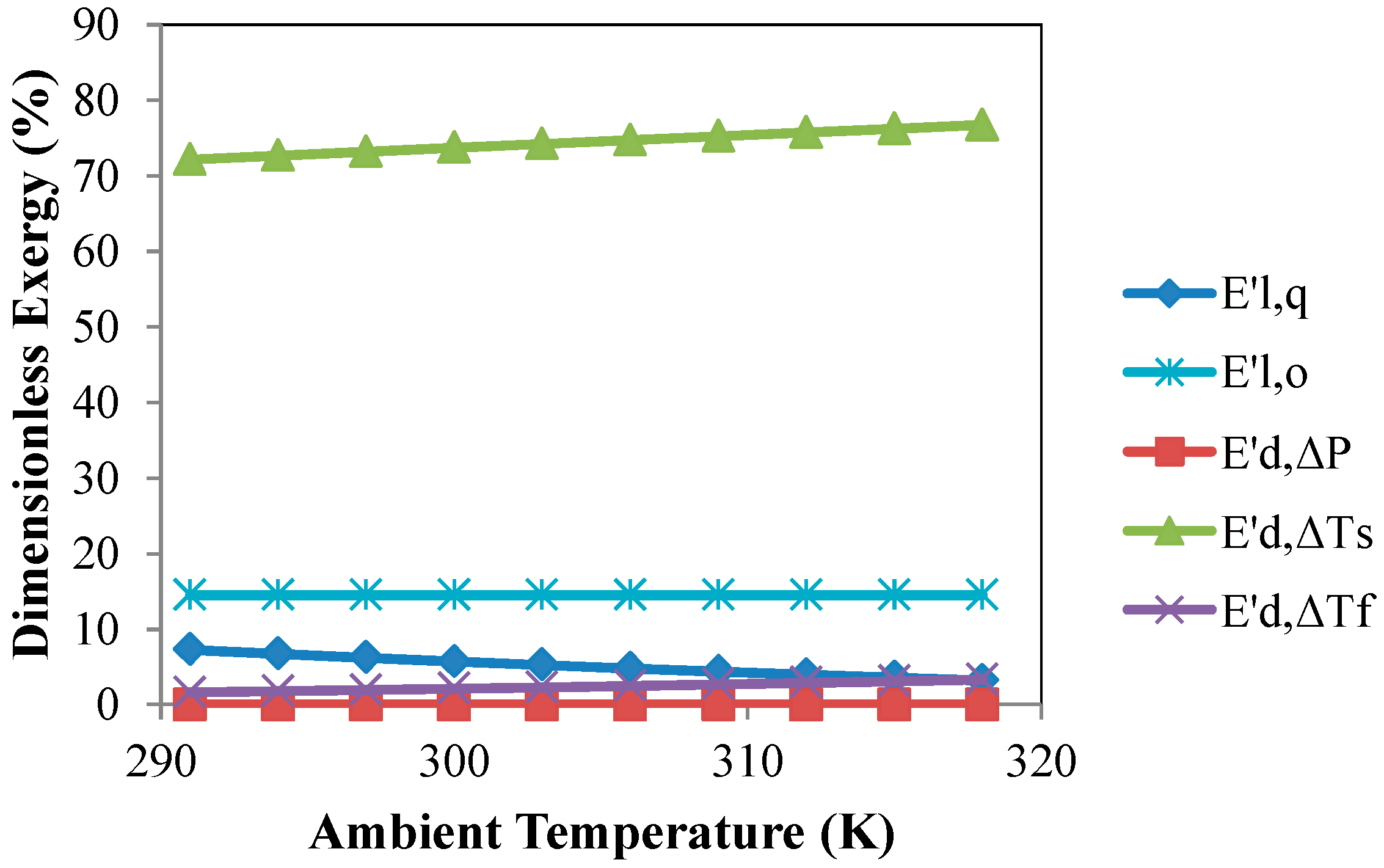
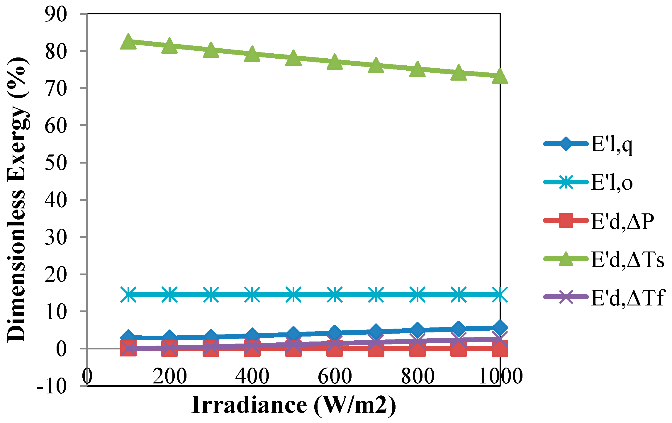
Figure 9, Figure 10, Figure 11, Figure 12 and Figure 13 show the dimensionless exergy destruction and loss components with respect to various parameters. Here, it can be seen that around 75% of the exergy destruction occurs due to the temperature difference between the sun and the absorber plate. Hence, increasing the absorber plate temperature can reduce this portion of exergy destruction. Basically, without using any solar concentrating device this portion of destruction cannot be minimized much. Zhong et al. [11] reported that about 73% of the exergy destruction is caused in similar case for flat plate collectors. In addition, it can be seen that 5% to 10% exergy loss occurs due to heat loss to the surrounding. Exergy destruction due to optical losses is found constant and the destruction due to pressure drop is found insignificant. The temperature difference between absorber plate and the heat transfer fluid contribute to very low portion of exergy destruction. The graph pattern is in good agreement for the curve for the parabolic trough receiver [26]. Figure 11 shows that the exergy loss due to optical loss reduces with the increasing optical efficiency.
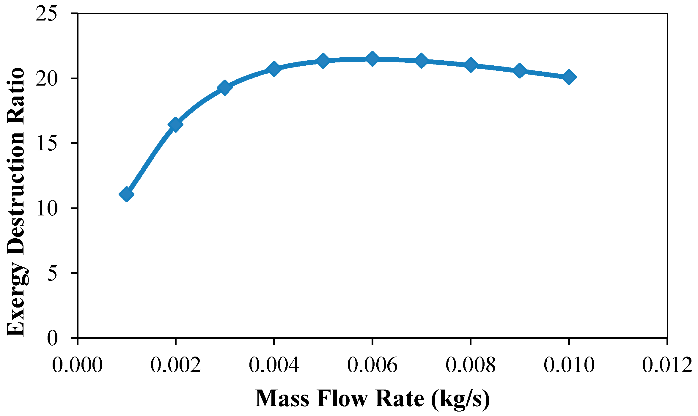
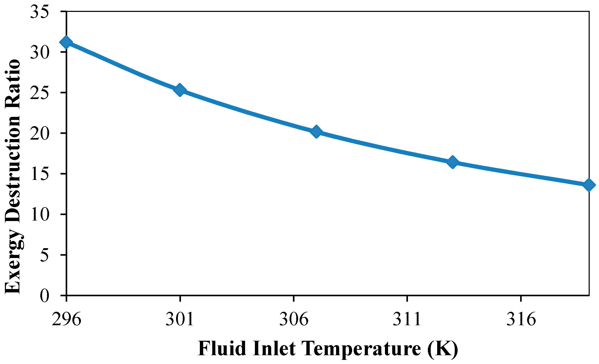
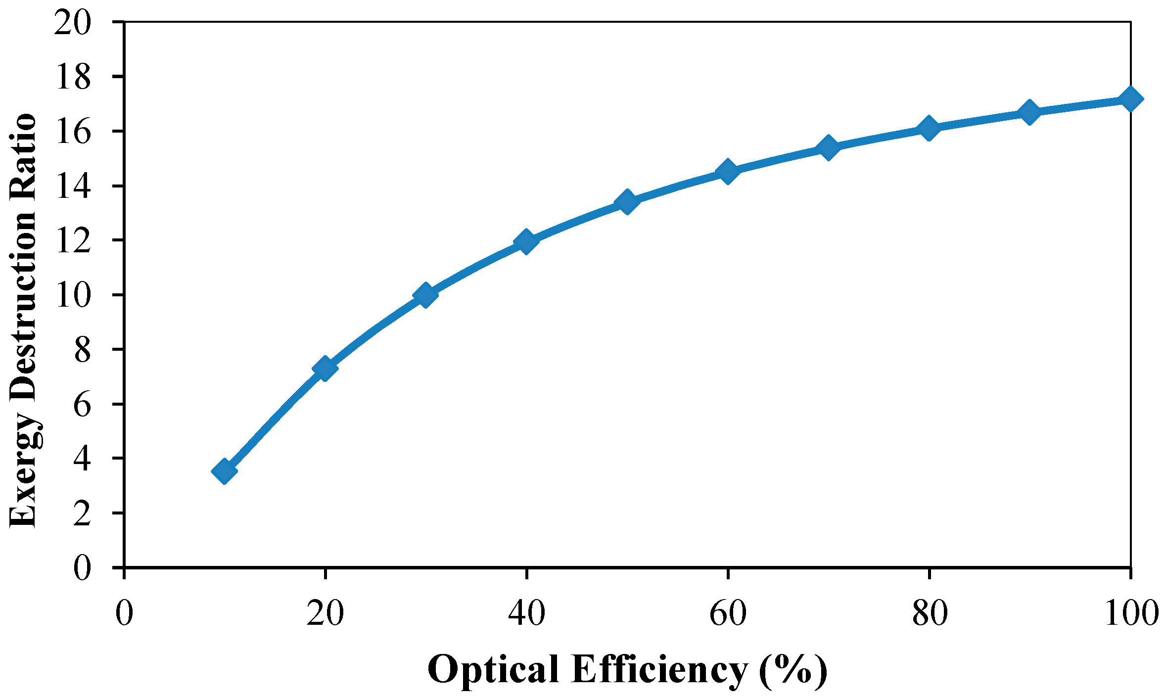
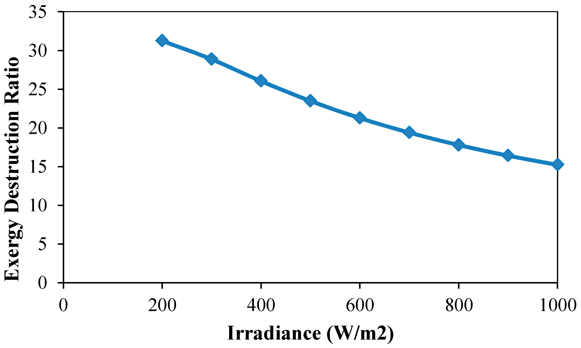
Figure 14, Figure 15, Figure 16, Figure 17 and Figure 18 graphically show the relationships between EDR and various parameters. With increasing value of fluid inlet temperature and irradiance, the EDR value decreases. In contrast, the response of EDR to ambient temperature, optical efficiency and mass flow rate is the opposite, i.e., EDR increases with these parameters.
For this type of passive solar collectors, it is not possible to measure the mass flow rate of water, so it was calculated numerically, as mentioned in Section 3.1. However, the response of various parameters with respect to mass flow rate was consistent with the results mentioned in other research. To simply the calculation of overall heat loss coefficient, collector heat removal factor and plate efficiency factor were considered constant, which is not the case practically.
5. Conclusions
Exergy analysis of the serpentine type thermosyphon solar water heater is performed based on some assumptions and model equations. Overall, heat loss coefficient, collector heat removal factor and plate efficiency factor are practically not constant over the operating range. However, precise calculation by iterative process will result better accuracy.
- This analysis is helpful in determining dimensions and operating conditions for the optimum performance of this type of system.
- Maximum exergy efficiency can be obtained over a certain inlet fluid temperature range, but the thermal efficiency decreased with increasing inlet temperature.
- Ambient temperature has positive effect on the thermal efficiency, whereas it has negative effect on the exergy efficiency.
- Both optical efficiency and irradiance have great positive impact on the performance of the water heater. Thermal efficiency and exergy efficiency increase with these two parameters.
- Thermal efficiency does not depend much on the mass flow rate of this type of passive system, while the exergy efficiency reduces at higher mass flow rate.
- Exergy efficiency of around 3.7% can be expected from this type of passive solar water heating system.
- Most (almost 75%) exergy destruction occurs due to high temperature difference between the sun and the absorber plate.
- Heat loss to the surrounding causes around 5% of exergy loss.
- EDR decreases with increasing fluid inlet temperature and irradiance.
Acknowledgments
The authors are grateful to the authority and staff members of Green Asia Education Center, Kyushu University for providing research support and cooperation in all respects. This work is financially supported by Green Asia Education Center, Kyushu University and MEXT, Japan.
Author Contributions
Muhammad Faisal Hasan and Md. Sayeed Ur Rahim Mahadi conceived and designed the experimental setup and performed the experiments. Muhammad Faisal Hasan conducted the data analysis and optimization. Kyaw Thu provided supervision and guidance with the exergy analysis. Muhammad Faisal Hasan performed simulation and drafted the manuscript in consultation with Kyaw Thu. Shigeru Koyama and Takahiko Miyazaki provided overall guidance and were involved in the discussion.
Conflicts of Interest
The founding sponsors had no obligation in the design of the study; in the collection, analyses, or interpretation of data; in the writing of the manuscript, and in the decision to publish the results.
Nomenclature
| area of absorber plate [m2] | |
| heat transfer rate [W] | |
| mass flow rate [kg/s] | |
| specific heat of fluid [J/kg K] | |
| absorbed solar radiation flux per unit time [W/m2] | |
| overall heat loss coefficient [W/m2 k] | |
| pressure difference between collector inlet and surrounding (tank) [Pa] | |
| temperature difference between absorber plate and the sun [K] | |
| Exergy rate [W] | |
| solar collector heat removal factor, dimensionless | |
| absorber plate efficiency factor, dimensionless | |
| irradiance [W/m2] | |
| outlet temperature [K] | |
| inlet temperature [K] | |
| ambient temperature [K] | |
| absorber plate average temperature [K] | |
| black body temperature of the sun [~5800 K] | |
| apparent temperature of the sun [~4350 K] | |
| h | enthalpy (J/kg) |
| c | velocity of flow (m/s) |
| g | acceleration due to gravity (9.81 m/s2) |
| z | height (m) |
| Greek symbols | |
| thermal efficiency | |
| optical efficiency | |
| transmittance-absorbtance product | |
| density of fluid [kg/m3] | |
| Petela efficiency | |
| exergetic efficiency | |
| Subscripts | |
| f | fluid |
| in | inlet |
| out | outlet |
| d | destruction |
| l | loss/leakage |
| o | optical |
| ab | absorbed |
| u | utilized |
| cv | control volume |
References
- Mahadi, M.S.-U.-R.; Hasan, M.F.; Ahammed, A.; Kibria, M.T.; Huque, S. Construction, fabrication and performance analysis of an indigenously built serpentine type thermosyphon solar water heater. In Proceedings of the 2014 3rd International Conference on the Developments in Renewable Energy Technology (ICDRET), Dhaka, Bangladesh, 29–31 May 2014; pp. 2–7. [Google Scholar]
- Liu, R.H.T.G.; Cengel, Y.A. Exergy Analysis of a Solar Heating System. J. Sol. Energy Eng. 1995, 117, 249–251. [Google Scholar] [CrossRef]
- Jafarkazemi, F.; Ahmadifard, E. Energetic and exergetic evaluation of flat plate solar collectors. Renew. Energy 2013, 56, 55–63. [Google Scholar] [CrossRef]
- Marletta, L. Air conditioning systems from a 2nd law perspective. Entropy 2013, 15, 859–877. [Google Scholar] [CrossRef]
- Yazdi, M.; Aliehyaei, M.; Rosen, M.A. Exergy, economic and environmental analyses of gas turbine inlet air cooling with a heat pump using a novel system configuration. Sustainability 2015, 7, 14259–14286. [Google Scholar] [CrossRef]
- Gertzos, K.P.; Caouris, Y.G.; Panidis, T. Optimal design and placement of serpentine heat exchangers for indirect heat withdrawal, inside flat plate integrated collector storage solar water heaters (ICSSWH). Renew. Energy 2010, 35, 1741–1750. [Google Scholar] [CrossRef]
- Xiaowu, W.; Ben, H. Exergy analysis of domestic-scale solar water heaters. Renew. Sustain. Energy Rev. 2005, 9, 638–645. [Google Scholar] [CrossRef]
- Ben, H. Analysis and Synthesis of Energy Utilization; Chinese Petrochemical Engineering Press: Beijing, China, 1995. [Google Scholar]
- Hossain, M.S.; Saidur, R.; Fayaz, H.; Rahim, N.A.; Islam, M.R.; Ahamed, J.U.; Rahman, M.M. Review on solar water heater collector and thermal energy performance of circulating pipe. Renew. Sustain. Energy Rev. 2011, 15, 3801–3812. [Google Scholar] [CrossRef]
- Gupta, M.K.; Kaushik, S.C. Exergetic performance evaluation and parametric studies of solar air heater. Energy 2008, 33, 1691–1702. [Google Scholar] [CrossRef]
- Ge, Z.; Wang, H.; Wang, H.; Zhang, S.; Guan, X. Exergy analysis of flat plate solar collectors. Entropy 2014, 16, 2549–2567. [Google Scholar] [CrossRef]
- Luminosu, I.; Fara, L. Determination of the optimal operation mode of a flat solar collector by exergetic analysis and numerical simulation. Energy 2005, 30, 731–747. [Google Scholar] [CrossRef]
- Torres-Reyes, E.; Gortari, J.C.; Ibarra-Salazar, B.; Picon-Nuñez, M. A design method of flat-plate solar collectors based on minimum entropy generation. Exergy Int. J. 2001, 1, 46–52. [Google Scholar] [CrossRef]
- Farahat, H.A.S.; Sarhaddi, F. Exergetic optimization of flat plate solar collectors. Renew. Energy J. 2009, 8, 1169–1174. [Google Scholar] [CrossRef]
- Kalogirou, S.A.; Karellas, S.; Braimakis, K.; Stanciu, C.; Badescu, V. Exergy analysis of solar thermal collectors and processes. Prog. Energy Combust. Sci. 2016, 56, 106–137. [Google Scholar] [CrossRef]
- Pandey, K.M.; Chaurasiya, R. A review on analysis and development of solar flat plate collector. Renew. Sustain. Energy Rev. 2017, 67, 641–650. [Google Scholar] [CrossRef]
- Kalogirou, S.A.; Karellas, S.; Badescu, V.; Braimakis, K. Exergy analysis on solar thermal systems: A better understanding of their sustainability. Renew. Energy 2016, 85, 1328–1333. [Google Scholar] [CrossRef]
- Saidur, R.; Boroumandjazi, G.; Mekhlif, S.; Jameel, M. Exergy analysis of solar energy applications. Renew. Sustain. Energy Rev. 2012, 16, 350–356. [Google Scholar] [CrossRef]
- Park, S.R.; Pandey, A.K.; Tyagi, V.V.; Tyagi, S.K. Energy and exergy analysis of typical renewable energy systems. Renew. Sustain. Energy Rev. 2014, 30, 105–123. [Google Scholar] [CrossRef]
- Colangelo, G.; Favale, E.; Miglietta, P.; De Risi, A. Innovation in flat solar thermal collectors: A review of the last ten years experimental results. Renew. Sustain. Energy Rev. 2016, 57, 1141–1159. [Google Scholar] [CrossRef]
- MKareem, W.; Habib, K.; Ruslan, M.H.; Saha, B.B. Thermal performance study of a multi-pass solar air heating collector system for drying of Roselle (Hibiscus sabdariffa). Renew. Energy 2017, 113, 281–292. [Google Scholar] [CrossRef]
- Kareem, M.W.; Habib, K.; Sopian, K.; Ruslan, M.H. Multi-pass solar air heating collector system for drying of screw-pine leaf (Pandanustectorius). Renew. Energy 2017, 112, 413–424. [Google Scholar] [CrossRef]
- Suzuki, A. General theory of exergy-balance analysis and application to solar collector. Energy 1988, 13, 153–160. [Google Scholar] [CrossRef]
- Matlab Optimization Toolbox, (n.d.). Avalaible online: https://www.mathworks.com/products/optimization.html (accessed on 25 January 2018).
- Cengel, Y.A.; Boles, M.A. Thermodynamics an Engineering Approach, 5th ed.; McGraw-Hill: Boston, MA, USA, 2005. [Google Scholar]
- Padilla, R.V.; Fontalvo, A.; Demirkaya, G.; Martinez, A.; Quiroga, A.G. Exergy analysis of parabolic trough solar receiver. Appl. Therm. Eng. 2014, 67, 579–586. [Google Scholar] [CrossRef]
- Arora, A.; Kaushik, S.C. Theoretical analysis of a vapour compression refrigeration system with R502, R404A and R507A. Int. J. Refrig. 2008, 31, 998–1005. [Google Scholar] [CrossRef]
- Sukhatme, S.P. Solar Energy; McGraw-Hil: New York, NY, USA, 1993. [Google Scholar]
- Duffie, J.A.; Beckman, W.A. Solar Engineering of Thermal Processes, 2nd ed.; John Wiley & Sons, Inc.: New York, NY, USA, 1980. [Google Scholar]
- Nag, P.K. Engineering Thermodynamics, 5th ed.; Tata McGraw-Hill Education: New York, NY, USA.
- Petela, R. Exergy of undiluted thermal radiation. Sol. Energy 2003, 74, 469–488. [Google Scholar] [CrossRef]
- Petela, R. Exergy of Heat Radiation. J. Heat Transf. 1964, 86, 187–192. [Google Scholar] [CrossRef]
Figure 1.
Serpentine Thermosyphon Solar Water Heater [1].
Figure 1.
Serpentine Thermosyphon Solar Water Heater [1].
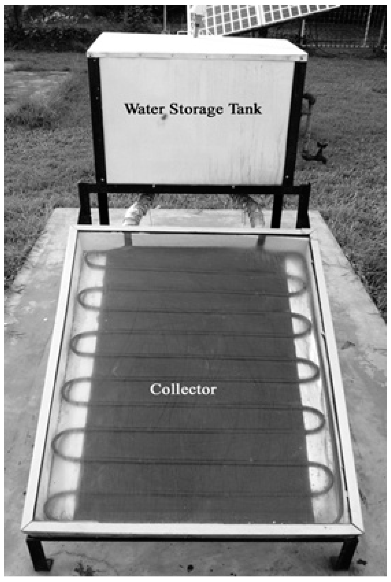
Figure 2.
Schematic of the collector [1].
Figure 2.
Schematic of the collector [1].

Figure 3.
Schematic diagram of the total setup of the solar water heating system [1].
Figure 3.
Schematic diagram of the total setup of the solar water heating system [1].
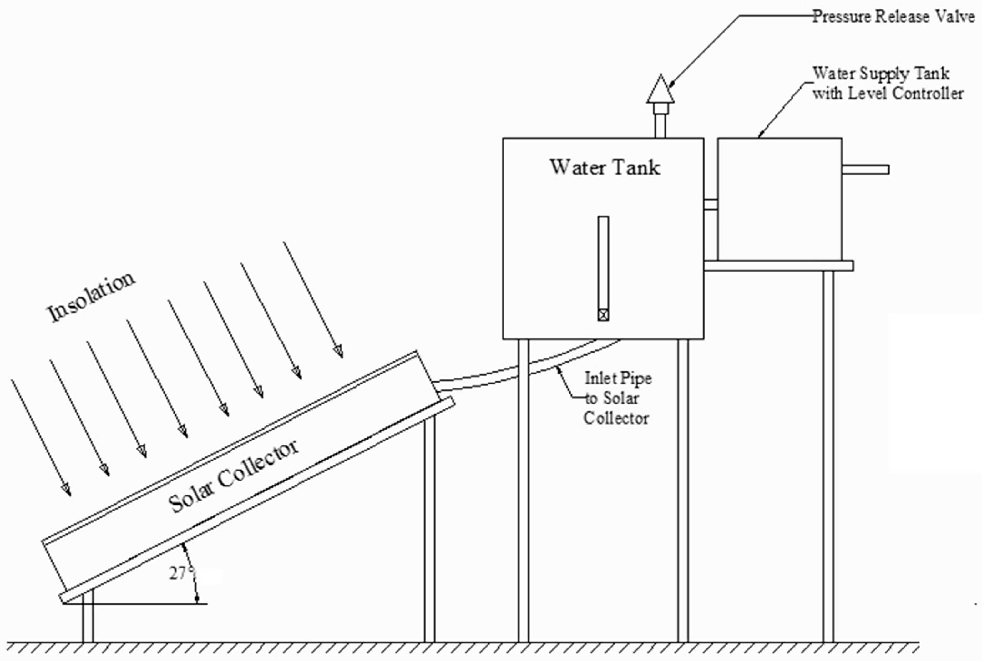
Figure 4.
Variation of exergetic efficiency and thermal efficiency with fluid inlet temperature.

Figure 5.
Variation of exergetic efficiency and thermal efficiency with ambient temperature.

Figure 6.
Variation of exergetic efficiency and thermal efficiency with optical efficiency.

Figure 7.
Variation of exergetic efficiency and thermal efficiency with irradiance.

Figure 8.
Variation of exergetic efficiency and thermal efficiency with mass flow rate.

Figure 9.
Variation of dimensionless exergy with fluid inlet temperature.
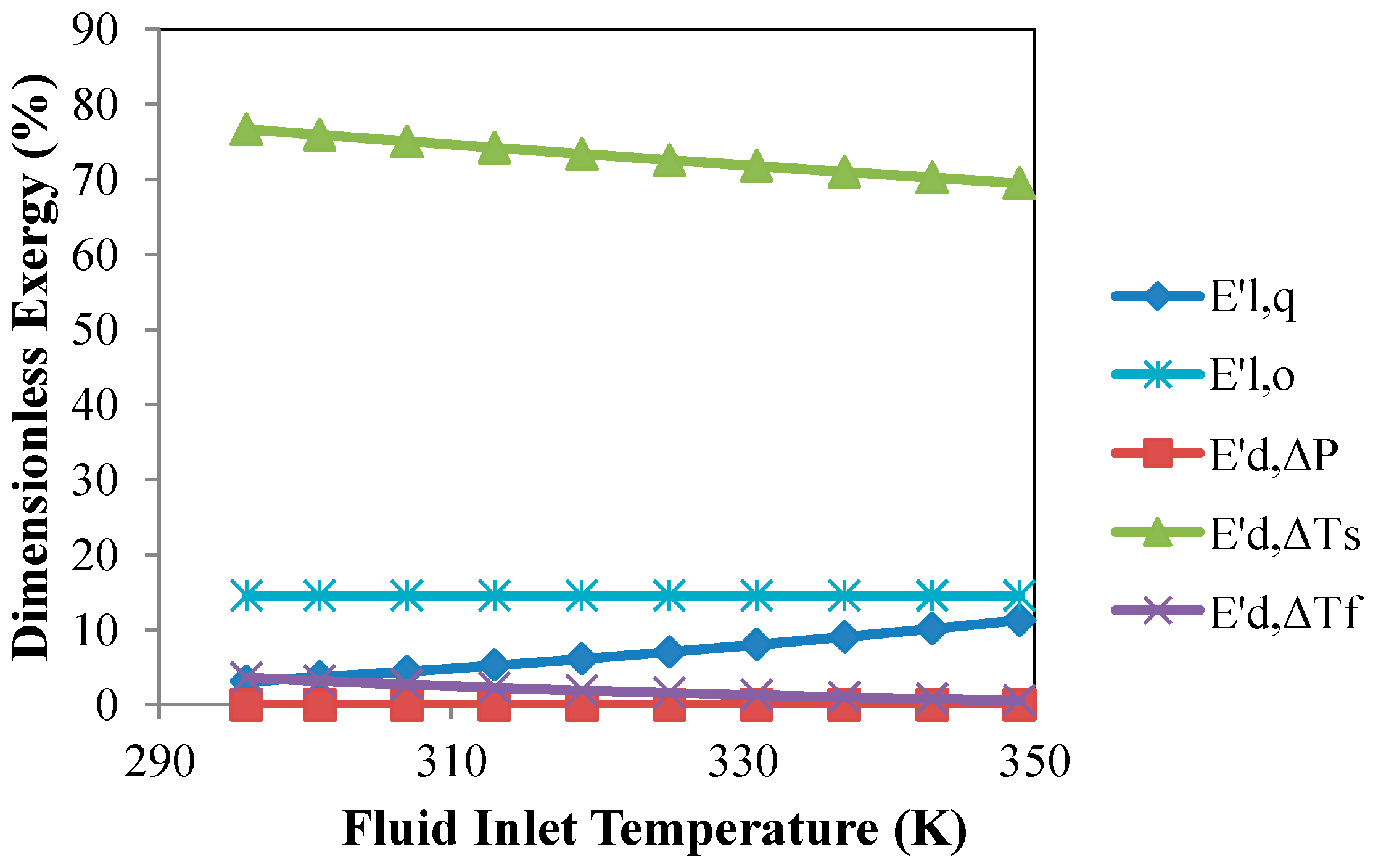
Figure 10.
Variation of dimensionless exergy with ambient temperature.

Figure 11.
Variation of dimensionless exergy with optical efficiency.
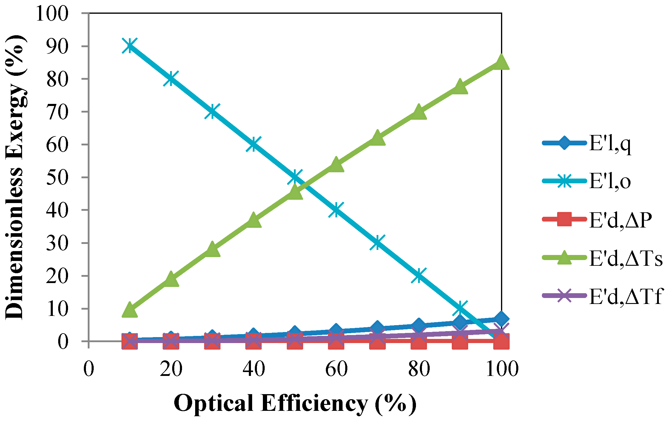
Figure 12.
Variation of dimensionless exergy with irradiance.

Figure 13.
Variation of dimensionless exergy with mass flow rate.
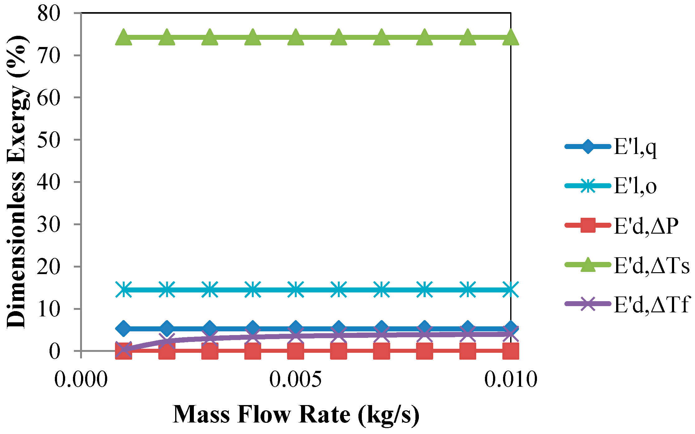
Figure 14.
Variation of exergetic destruction ratio with fluid inlet temperature.

Figure 15.
Variation of exergetic destruction ratio with ambient temperature.
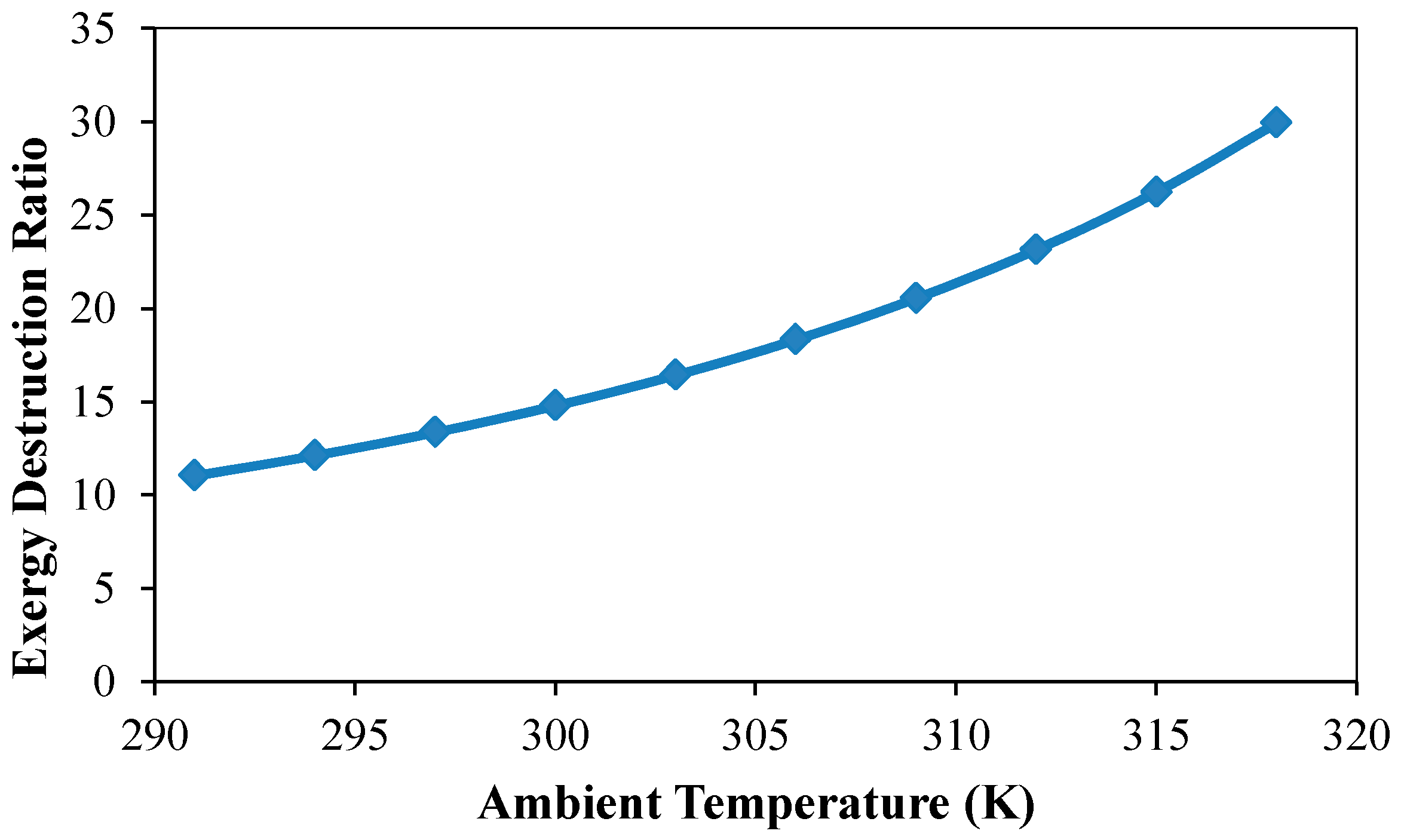
Figure 16.
Variation of exergetic destruction ratio with optical efficiency.

Figure 17.
Variation of exergetic destruction ratio with irradiance.

Figure 18.
Variation of exergetic destruction ratio with mass flow rate.

Table 1.
Some parameters specification.
| Parameter | Value | |
|---|---|---|
| Absorber plate material | : | Copper |
| Dimensions of the absorber plate: | : | 1 m × 0.6 m |
| Plate thickness | : | 0.2 mm |
| Serpentine pipe material | : | Copper |
| Serpentine pipe inner diameter | : | 10 mm |
| Serpentine pipe thickness | : | 1.5 mm |
| Glazing material | : | Tempered glass |
| Glazing dimensions | : | 1.05 m × 0.81 m |
| Glazing thickness | : | 5 mm |
| Insulation | : | Glass wool and cork sheet |
| Collector tilt angle | : | 27° |
| Thermal conductivity of absorber | : | 401 W/(m K) |
| Thermal conductivity of insulation | : | 0.04 W/(m K) |
| transmittance-absorptance product | : | 0.855 |
| Apparent sun temperature | : | 4350 K |
| Ambient temperature | : | 303 K |
| Irradiance | : | 900 W/m2 |
© 2018 by the authors. Licensee MDPI, Basel, Switzerland. This article is an open access article distributed under the terms and conditions of the Creative Commons Attribution (CC BY) license (http://creativecommons.org/licenses/by/4.0/).
Share and Cite
MDPI and ACS Style
Hasan, M.F.; Mahadi, M.S.U.R.; Miyazaki, T.; Koyama, S.; Thu, K. Exergy Analysis of Serpentine Thermosyphon Solar Water Heater. Appl. Sci. 2018, 8, 391. https://doi.org/10.3390/app8030391
AMA Style
Hasan MF, Mahadi MSUR, Miyazaki T, Koyama S, Thu K. Exergy Analysis of Serpentine Thermosyphon Solar Water Heater. Applied Sciences. 2018; 8(3):391. https://doi.org/10.3390/app8030391
Chicago/Turabian StyleHasan, Muhammad Faisal, Md. Sayeed Ur Rahim Mahadi, Takahiko Miyazaki, Shigeru Koyama, and Kyaw Thu. 2018. "Exergy Analysis of Serpentine Thermosyphon Solar Water Heater" Applied Sciences 8, no. 3: 391. https://doi.org/10.3390/app8030391
Note that from the first issue of 2016, this journal uses article numbers instead of page numbers. See further details here.