Article

Development of a High-Fidelity Model for an Electrically Driven Energy Storage Flywheel Suitable for Small Scale Residential Applications

School of Mathematics, Computer Science and Engineering, University of London, London EC1V 0HB, UK
*
Authors to whom correspondence should be addressed.
Appl. Sci. 2018, 8(3), 453; https://doi.org/10.3390/app8030453
Submission received: 13 November 2017 / Revised: 8 March 2018 / Accepted: 8 March 2018 / Published: 16 March 2018
(This article belongs to the Special Issue Smart Home and Energy Management Systems)

Abstract

:
Energy storage systems (ESS) are key elements that can be used to improve electrical system efficiency by contributing to balance of supply and demand. They provide a means for enhancing the power quality and stability of electrical systems. They can enhance electrical system flexibility by mitigating supply intermittency, which has recently become problematic, due to the increased penetration of renewable generation. Flywheel energy storage systems (FESS) are a technology in which there is gathering interest due to a number of advantages offered over other storage solutions. These technical qualities attributed to flywheels include high power density, low environmental impact, long operational life, high round-trip efficiency and high cycle life. Furthermore, when configured in banks, they can store MJ levels of energy without any upper limit. Flywheels configured for grid connected operation are systems comprising of a mechanical part, the flywheel rotor, bearings and casings, and the electric drive part, inclusive of motor-generator (MG) and power electronics. This contribution focusses on the modelling and simulation of a high inertia FESS for energy storage applications which has the potential for use in the residential sector in more challenging situations, a subject area in which there are few publications. The type of electrical machine employed is a permanent magnet synchronous motor (PMSM) and this, along with the power electronics drive, is simulated in the MATLAB/Simulink environment. A brief description of the flywheel structure and applications are given as a means of providing context for the electrical modelling and simulation reported. The simulated results show that the system run-down losses are 5% per hour, with overall roundtrip efficiency of 88%. The flywheel speed and energy storage pattern comply with the torque variations, whilst the DC-bus voltage remains constant and stable within ±3% of the rated voltage, regardless of load fluctuations.

1. Introduction

Energy storage systems (ESS) can provide a viable solution to the problem of balancing electrical energy supply and demand. This is achieved through the process of converting stored electrical energy into one of the forms of thermal, magnetic, mechanical, or chemical energy [1,2]. ESS enables energy to be stored when the generation exceeds demand, and produced when it is needed. Storage is beneficial when there is low demand, low generation cost, or when available sources of energy are intermittent. Alternatively, the stored energy can be consumed at times of high generation cost, high demand, or when alternative generation is not available [1,2,3,4].
Energy demand continues to increase with high growth rates, which would increase energy prices if there is no change from use of traditional generation methods. Pressures to limit carbon dioxide emissions, market deregulation, as well as power quality problems, in turn add to aggravating the issue of imbalances between generation and demand [2,3]. Potential distributed generation (DG) and renewable energy sources (RES) can be considered as replacements or supplements for traditional generation methods [3]. Yet there are major obstacles linked to energy being supplied from renewables, due to their intermittent nature across a range of timescales [4]. Their availability is always subject to weather conditions, and there are annual, seasonal, and monthly fluctuations in RES supply which may not match the periods of energy demand [3,4]. Therefore, ESS are a vital necessity to supplement intermittent RES for integration into the electrical network and meet the excessive demand by aggregating the traditional generating plants [5].
There is a high demand for cost effective, reliable, long lasting, and environmentally friendly energy storage systems to support a variety of applications in modern electrical networks. There have been significant developments in flywheel technology due to advances in materials technology, power electronics, and bearings [6,7]. High energy efficiency flywheels that also possess high power and energy densities, vie with other electrical power storage solutions, as well as in the transportation, military and space satellite industry sectors [8]. With power ranges from kW to GW, and up to 500 MJ storage capability per machine, they are able to provide solutions for many significant energy storage applications in an electrical power system [8,9]. In electrical energy storage applications, flywheels are widely used for uninterruptible power supplies, as well as for improving power quality problems [10,11,12]. As these applications require a high number of cycles per day, the electrochemical battery suffers from insufficient cycle life and is highly mismatched [13].
There has been a growing need for storing energy in residential premises, which is attractive for providing arbitrage type storage for buildings with solar panels. Most of these are connected to a stable grid and the incentive for the consumer is to have storage behind the meter, which reduces energy bills. The energy storage system of choice for residential photovoltaic (PV) systems is more typically an electrochemical battery, whereas flywheels have not been widely tested nor considered for this application. Such batteries are typically Li-ion or lead acid chemistries promoted very publicly by companies such as Tesla and several others [14]. However, there is an issue of degradation in hotter countries, where the combination of ambient temperature and heat generated within the battery can lead to reduced life guarantees as evidenced by their warranties [15]. In addition, there are many countries where the grid is highly unreliable, so when the grid fails, the power ramp up must be in milliseconds, effectively similar to the requirements of a UPS system. Diesel generators are also commonly installed in residences in countries with intermittent grids, and this changes the storage system requirements to one of increased number of cycles. A battery is hence less favourable for these applications as compared to their implementation in developed countries. Of course, the batteries are mass produced, and are currently more cost effective than flywheels, but flywheels will still be a viable choice when it comes to numerous cycles per day. A battery will be more comfortable providing storage for only 1 cycle per day if it is managed carefully, both electrically and thermally, so that its depth of discharge is kept low. This can be done by oversizing the storage, so it will be able to last for 10 years (3650 cycles). However, this would require energy storage to be sized at 2–5 times the required capacity, to reduce depth of discharge leading to higher costs. In examples where batteries are installed for solar arbitrage, cycles are, on average, less than 1 per day, and depth of discharge may be low, since not all days are fully sunny. Supercapacitors, with a capital cost more or less the same as flywheels [1], have also been tested for the same applications. However, they have a relatively low lifetime, reaching a maximum 12 years [3]. To reduce cost and minimise capacity, it will be advantageous to use the storage system many times in a day. The flywheel system can also take part in the time shifting of electrical demand, and even fed into the grid when there is a high demand. This paradigm of energy storage will find more interest and will be greatly enhanced when time of use (ToU) tariffs are applied.
Due to the advantage of being able to deal with a high number of daily cycles, flywheels offer a much improved lifespan compared to their chemical storage alternatives. Further, for the same rated power, a flywheel will take up much less space than a battery for applications as described where the C rating (power to energy ratios) is high. In addition, flywheels are less sensitive to ambient temperature, and do not need to be in a cooled or heated enclosure. Finally, there is a growing environmental concern when disposing of spent chemical batteries, particularly more difficult in less developed countries. Flywheels do not have this issue. There are several advantages of flywheel energy storage systems (FESS) over chemical storage systems, but a flywheel is likely to incur a higher initial capital cost, although with high longevity, lifetime costs will be lower. As a means of reducing flywheel costs, what is being proposed here is FESS based on laminated steel with a view to overcoming the drawback of the aforementioned high initial costs of a high speed composite based system.
Many publications have addressed the mechanical aspects, such as the bearing systems and rotor dynamics of the flywheels. To name a few, rotor design and analysis of composite rotor FESS is discussed in [16]. Authors in [17] present modelling and simulation of the rotor of a composite flywheel at different speeds. Dynamic analysis and control of an active magnetic bearing FESS is studied in [18], and its vibration control for high speed applications is discussed in [19]. A model of a FESS with integrated bearing system is proposed in [20], and a thorough analysis, design, and control of a novel flywheel assisted by hybrid mechanical–magnetic bearings is presented in [21]. A subject area in which there is a scarcity of publications is the modelling and simulation of the electrical characteristics of flywheel systems when used for ground power applications. Particularly, for small scale customer level where flywheels can support residential PV systems, there is not enough information in the literature and there are no commercially available flywheel storage systems for these applications. Most flywheel manufacturers are providing high power fast-response flywheels for power quality and UPS applications. Filling this gap in the literature is necessary, but remains as a challenging task, since availability of practical data for FESS suitable for energy storage applications is very limited. This paper therefore presents a simulation and analysis of a permanent magnet synchronous motor (PMSM) operated flywheel system using MATLAB/Simulink. A detailed model of a higher inertia FESS suitable for ground power applications at the residential level is discussed, and its dynamic performance, including system losses, under different charge–discharge scenarios, is analysed. The mathematical loss model of the system is derived, and efficiency and total run-down losses are determined.
Following the introduction, a description of the FESS and its main components including the rotor, electrical machine, bearings, and flywheel containment are briefly discussed in Section 2. The flywheel’s characteristics and main applications are described in Section 3 and Section 4, respectively. The core contribution commences in Section 5 and Section 6, in which the calculation of losses and model structure and conventions for the electrical machine and drive are described in detail. The results of the simulations using the model and key findings are described in Section 7, and the paper is concluded in Section 8.

2. Description of Flywheel Energy Storage Systems

2.1. Background

The flywheel is one of the most primitive mechanical energy storage systems which has been in existence for thousands of years. The potter’s wheel was one of the earliest forms of rotary objects using its own inertia to maintain energy [22]. The name “flywheel” emerged as a result of the industrial revolution, where flywheels were used to operate as energy accumulators, as well as in steam engine trains and boats (namely in 1784) [23]. Despite its existence for millennia and implementation of numerous designs and shapes, there have not been major developments on flywheels until very recently. It was only at the beginning of the 20th century that flywheels appeared as potential energy storage systems as a result of major developments on rotor shapes and thorough analysis of the rotational stress [24]. In 1960s and 1970s, FESS was proposed for electric vehicles, stationary power backup, and space missions [9,10]. In the following immediate years, fibre composite rotors were built and tested. In 1980s, relatively low speed magnetic bearings started to appear [25].
Although flywheels have been improved for use in different areas, their utilisation as energy storage systems deteriorated with the expansion and improvements of the electrical grid. However, recent major developments in materials, bearing systems, power electronics, and development of high speed electric machines have enabled flywheels to perform energy storage applications and emerge as a promising technology competing with many other storage systems [7,8,9,26,27].
A flywheel is a mechanical storage system operating on the principal of a rotating mass to store energy. It converts the electrical energy into mechanical energy and stores it as rotational kinetic energy. The flywheel is charged by extracting electrical energy from an available source to accelerate the rotor speed and accumulate energy. It is discharged by delivering the stored energy back into its electrical form. The operation of the flywheel is controlled by an electrical machine functioning as a motor-generator (MG) to perform the energy conversion between electrical and mechanical forms [28,29]. The flywheel and the MG are coupled on the same shaft, which enables the FESS to be controlled by the operation of the MG [30,31,32,33].

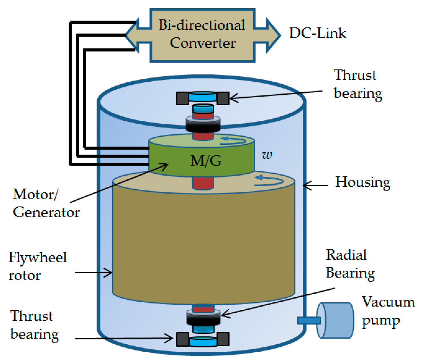
2.2. Structure and Components of FESS: Priciples and Components of FESS

FESS consists of a spinning rotor, MG, bearings, power electronics interface, and containment or housing. A schematic of a typical flywheel system suitable for ground based power applications is shown in Figure 1.

2.2.1. The Rotor

The energy stored in a flywheel is a function of its material and rotor shape. It is proportional to the square of the angular velocity and is linear to the moment of inertia, which is determined by the rotor shape and material as shown in Equation (1) [27,34]:
E = 1 2 I ω 2
where E is the stored energy, and I and ω are the moment of inertia and angular velocity of the flywheel rotor, respectively. This allows optimization of the stored energy of a flywheel by either increasing I or ω . Typically, a flywheel driven by an electrical machine operates between a minimum speed (𝜔min) and maximum speed (𝜔max) to limit maximum torque on the MG for a given power rating, and also avoid abundant voltage variations. The useful stored energy of the flywheel between (𝜔min) and (𝜔max) can be obtained by
E = 1 2 I ( ω max 2 ω min 2 )   =   1 2 I ω max 2 ( 1 ω min 2 ω max 2 )
The moment of inertia is determined by the shape factor and mass of the flywheel rotor. The flywheel rotor can be solid or a hollow cylinder-shape, ranging from short and disc-type to long and drum type [28,34]. The moment of inertia of a solid cylinder or disc type flywheel is given by
I = 1 2 m r 2
where m and r represent the mass and radius of the rotor, respectively. The moment of inertia for hollow cylinder flywheel with inner radius a and outer radius b is
I = 1 2 m ( b 2 + a 2 )
The moment of inertia as a function of mass density ρ and length h is obtained by
I = 1 2 π ρ h ( b 4 a 4 )
Therefore, using Equations (1) and (5),
E = 1 4 π ρ h ω 2 ( b 4 a 4 )
The maximum speed of the flywheel rotor is limited by the tensile strength σ of the rotor material given by [24,35]
σ max = ρ r 2 ω 2
Equation (7) indicates the maximum tensile stress of a thin rotating ring with material density ρ . The geometric effect of the rotor on the maximum stored energy is introduced by the shape factor K. The K value ranges between 0 and 1, depending on the geometry of the flywheel rotor. Flywheel specific energy and energy density as a function of the shape factor K are presented in Equations (8) and (9):
E m = K σ max ρ   [ J / kg ]
E V = K σ max   [ J / m 3 ]
Based on the rotational speed, flywheels can be classified as low speed (up to 1000 rad/s) or high speed (up to 10,000 rad/s) [35]. Heavy metallic materials are usually used for low speed flywheel rotors, while high speed flywheels are made of strong composite materials with lower density. A new class of flywheels with intermediate speed range and laminated steel material is also developed. The laminated steel rotor uses high strength, low-cost steel, but avoids the safety issue of solid steel by ensuring only a small part of the rotor is displaced at the time failure [36].

Intermediate Speed Flywheels

A new class of intermediate speed flywheel is under development based on the use of steel laminates with a construction that eliminates the stress raising feature of a central hole normally required for composite flywheel. The peripheral speed of the flywheel can be much higher than what would be considered safe for a solid monolithic structure [37]. The catastrophic fracture in the rotor by fatigue crack is restricted to a single laminate which will only release a small fraction of the energy contained.
It is relatively simple to compare the steel laminated flywheel rotor with a composite for an assumed value of peripheral speed based on realistic maximum operating stresses in the two materials. The moment of inertia is a geometric value, and the energy stored is then proportional to material density and the square of the speed (Equation (6)). From this analysis, the rotor mass and volume ratio of steel relative to composite can be found as shown in Table 1.
Interestingly the mass of the steel rotor is over 4 times higher, but its volume is halved. It should be noted that the volume of the carbon fibre rotor is considered based on its external dimensions which govern the space taken up by the rotor. In some cases, this space may be usefully used by placing the electric MG inside it.
The peripheral speeds of composite rotors on commercially available flywheels are typically limited to less than 800 m/s. This is much lower than is achievable, theoretically, due to variation in material properties and diminishing returns when the weight and cost of containment outweighs the gains of operating at higher speeds. In many cases, rotor peripheral speeds are even less for these reasons. In a composite flywheel, the entire flywheel typically fails in a rotor failure, and even though the size of the fragments is small, all the energy is released at once. As an alternative to heavy containment, the flywheel can be buried underground, but this adds cost in a different way. Many commercially available systems need to rely on this method, but it means a much greater footprint is required for the installation as well as the civil engineering costs, including flood prevention.
For the ground based residential storage system, a flywheel of capacity 5 kWh is proposed, whose rotor is shown in Figure 2. The dimensions of the rotor are approximately 0.4 m diameter with 0.5 m height, giving the stated capacity within a working speed range of 10–20 krpm. The motor–generator, not shown, would be bolted directly onto the flywheel rotor for a power level that can be selected to suit the application.

2.2.2. Electric Machine

The flywheel rotor is coupled to an electrical machine (integrated MG) to help with the charging process and control the energy conversion of the FESS. The FESS is charged by extracting energy from an electrical source and accelerating the high inertia rotor of the flywheel. It is discharged by drawing the accumulated energy back from the flywheel rotor using the same MG, operating as a generator. Commonly used electrical machines operating in FESS are permanent magnet machine (PM), induction machine (IM), and variable reluctant machine (VRM) [24,35]. The PM machine with attributes of high power density, high efficiency, and low rotor losses is the most widely used electrical machine in flywheels. The main types of permanent magnet machines for FESS applications are permanent magnet synchronous machine (PMSM), brushless DC machine (BLDCM), and Halbach array machine (HAM). PM is abundantly used in high speed applications because of speed limitations of IM and torque ripple, vibration, and noise of VRM. The problem with PM machine is electromagnetic drag torque losses due to eddy current and iron losses in the stator, high price, and low tensile strength of the magnet, which must be contained by a containment structure [35]. This higher idling loss disadvantage is less of an issue if the number of daily charge–discharge cycles is high, and can be compensated by the higher efficiency of the energy transfer. To take advantage of both PM and VRM, hybrid PM reluctance machines have been recently developed. A comparison between PMs, IMs, and VRMs is presented in [38], while some other unconventional electrical machines used in FESS are discussed in [39]. Some of the recent developments of electric machines for FESS are studied in [40].

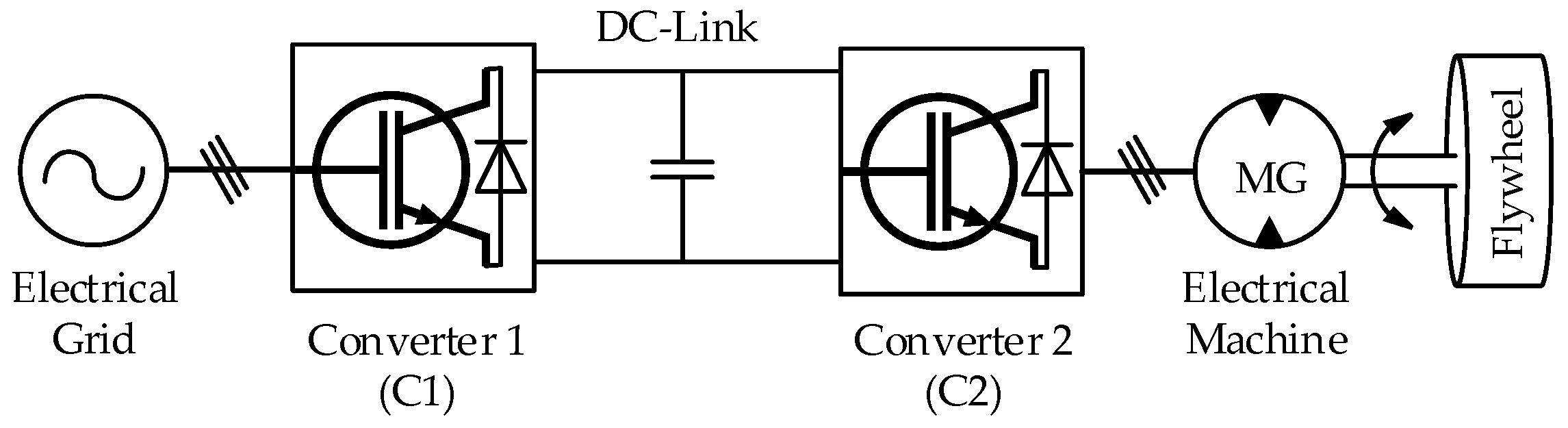
2.2.3. Power Electronics Interface

A bi-directional converter and an electrical machine are used to accomplish energy conversion in a FESS. DC-AC, AC-DC-AC, AC-AC or a combination of these power electronics topologies can be used with FESS applications. The back-to-back (BTB) or AC-DC-AC switching combination, connected to a DC link capacitor, is the most widely used power converter configuration with FESS. In the BTB topology, the converters are the three-phase bridged semiconductor switch type, often controlled using the pulse width modulation technique (PWM) [35]. Through the modulation of the width of rectangular pulses applied to the gates/bases of power semiconductors, space vector pulse width modulation (SVPWM) is used to control inputs to power electronic converters, and can therefore effect changes in electrical energy, such as the conversion from DC to sinusoidal single phase or three phase AC [9,41]. The operation of the MG and flywheel is controlled by a machine side converter, whereas a grid side converter is used to maintain the DC link voltage.
DC-DC boost converters are employed in cases where the FESS’ discharge speed is low, and the output voltage needs to be maintained. They would be connected between the BTB converters at the DC link to regulate the output voltage. A switch can be used to bypass the DC-DC boost converter during the charging phase [42].
Current ripples at the DC bus can be attenuated by using higher switching frequencies for both rectifier and inverter. An improved sinewave shape is produced due to the reduction of higher order harmonics because of faster converter switching times. This, in turn, can increase control bandwidth, but as a consequence, there will be additional switching losses. AC filters introduced on the converter AC side can assist to further reduced harmonics. Filters can also assist in the reduction of current ripples, winding deterioration, and losses [43,44].

2.2.4. Bearing System

Bearing systems are required to provide low friction support to keep the flywheel rotor in position [3]. They serve as a crucial component in a FESS that would lead to higher losses and increased operational and maintenance requirements if not correctly designed. Lifecycle life, weight, and losses are the key elements in deciding between mechanical or magnetic bearing systems [7]. Mechanical bearings incur friction and maintenance due to the lubricant that deteriorates over the time and requires changing [7]. On the other hand, magnet bearing systems are frictionless and they do not require any form of lubrication, but external energization power may be needed depending on type. Magnetic bearings support the weight of the flywheel rotor with permanent magnets which would require power to keep the magnets energised [9]. Superconducting magnetic bearing (SMB), active magnetic bearing (AMB), and permanent (passive) magnetic bearing (PMB) are the main forms of magnetic bearing mechanisms [45]. Sometimes both mechanical and magnetic bearings are combined to provide a cost effective as well as stable solution. Hybrid bearings will reduce the control system complexity and also minimise the rotational losses of the FESS [20]. A compact FESS assisted by hybrid bearing system is analysed in [21]. The rotational and translational support is provided by a mechanical bearing while the vertical levitation support is assisted by a magnetic bearing. This is the type of bearing system used for the flywheel modelled here. A combined magnetic bearing system supported by PMB and SMB is discussed in [46], where it is proposed to reduce the cost associated with the cooling system. The rotor vibration is suppressed by controlling the position of the flywheel rotor using SMB and PMB mechanisms.

2.2.5. Containment

The self-discharge rate of a flywheel in atmospheric pressure is high, and these losses increase with the cube of the speed of rotation due to aerodynamic drag losses [24]. The casing or housing is a low pressure environment to enclose the rotor in the event of any possible failures, and to keep the self-discharge losses to a minimum [28,29,47]. It is the stationary component of the flywheel system that is made of high strength composite material or thick steel, depending on the application and tip speed of the flywheel rotor. The aerodynamic drag loss is controlled by maintaining the rotor in a low-pressure container equipped with a vacuum pump. The pump and the cooling system are used to handle the pressure inside the vacuum and control the heat generated from the electrical machine [24]. Since with electrical energy transfer, the whole flywheel with MG can be hermetically sealed, the vacuum pump does not have to run continuously, but can be intermittent. If the rotor is steel, the vacuum requirement is reduced, due to lower rotor peripheral speeds. Given minimal outgassing, if the system is sealed well, it may not be required to install a vacuum pump, but rather, pump down during commissioning and remove the pump. When it comes to safety requirements of the rotor failure, composite material rotors tend to break into many small fragments and each fragment rotates inside the enclosure, leading to loss of its energy due to friction. However, the explosive failure mode can create very high pressure to build up inside the casing. This demands a robust containment with pressure during the catastrophic failure reported to be up to a few thousand bar. However, this will be different for single piece steel made rotors, since they burst into bigger fragments requiring even large containment systems. As explained in the rotor section, a laminated steel flywheel rotor can mitigate this issue, since thinner steel discs would release a fraction of the flywheel rotor in the event of a rotor failure.

3. Characteristics of FESS

The principal characteristics of flywheels are high energy density and power density [7,9], high charge and discharge rates, high round trip efficiency, rapid response, durability (greater than 20 years) and high cycle life (hundreds of thousands) with low environmental impacts [2,3,9,28,29,48]. The rotational speed is used to easily measure the state of charge, as it is unaffected by temperature or wear [9]. There are drawbacks, however, such as a higher self-discharge rate compared to other storage mediums and the hazardous nature of flywheel rotors, if not safely designed. In comparing the self-discharge of a flywheel to other storage technologies, it is important to also account for energy of auxiliaries required to maintain the whole system, i.e., a maintenance loss. For instance, many battery systems need to be heated or cooled, and so this incurs a loss to be added to any actual self-discharge, which is relatively small for batteries.
Flywheels have a long lifespan, with very low maintenance and operational requirements. Compared to other energy storage systems, flywheel cycle life is quite high as there is no requirement for long charge–discharge cycles. The charge–discharge cycle can occur rapidly based on the functionality and application, and is unaffected by the depth of discharge (DoD). It is estimated that FESS can last more than 20 years, and that there would be no performance deterioration, despite a charge–discharge cycle life of hundreds of thousands [3,28,29]. The technology has the capability to transfer large amounts of power (in seconds) with a high 90–95% range of roundtrip efficiency [1,2,35]. Its stored energy can be delivered, followed by a rapid recharge, within a matter of seconds. Further, since the construction material in FESS is not harmful to the environment and there are no emissions produced when in operation, it can be considered as environmentally friendly [29,35]. Flywheel energy and power ratings are independent, and can thus be optimised for a specific energy storage application. The size of the MG and related power electronics help to determine the power rating of a flywheel, whereas the speed and size of the rotor contributes to the determination of the energy rating [3,8].
Flywheels are widely used in applications where a high power output for short periods is required. The overall dimension of a FESS unit is a vital characteristic that puts it in competition with some other energy storage technologies. The power densities of batteries can be as much as five to ten times less than that of flywheels. Because flywheel systems take up less volumetric space and have a longer operational life, they can be a worthy replacement for batteries in applications such as space vehicles and transportation [8]. Another area yet not explored is the application of flywheels in residential solar photovoltaic systems, where they can operate as a standalone storage system or supplement chemical batteries.

4. Applications of FESS

There are numerous uses for flywheels in industry, ranging from the large scale electrical grid level, to the small scale consumer level [8,9]. Flywheels can be arranged in banks in order to achieve high power capacity and density instead of using larger machines [49]. But the most suitable flywheel applications concern the requirement for high power output over a short duration (e.g., 100s of kW/10s of seconds) [6] where there are frequent charge–discharge cycles [8]. The most common applications concern power quality, such as voltage and frequency regulation [50,51,52,53,54,55], pulsed power applications for the military [48], attitude control in space craft [48], UPS [8,12,35], load levelling [2], transportation (such as trains and hybrid and electric vehicles) [7,8,56], and energy storage applications [48].
Generally, FESS is classified as short-term response with high power density, with the ability to respond within seconds [57]. Storage duration can be prolonged to few hours without the loss of excessive amounts of energy as long as run-down losses are kept to a minimum. Flywheels can assist with the improvement of system stability where wind and solar energy penetrate an island system or are integrated into a power system. Due to flywheels having fast response characteristics, they are suitable in RES applications where grid frequency needs to be balanced. Power variations due to wind and solar fluctuations can be compensated by storing energy during low demand windy or sunny periods, and then supplied back during times of high demand [9,10]. Flywheels can be used to improve the system frequency by rectifying wind oscillations; whereas in solar PV systems, they can be incorporated with chemical batteries to improve system output and prolong the battery’s operational lifetime [9].
As part of its applications in energy storage, flywheels are able to accomplish this task both at the grid as well as at the customer level. They can be used to supplement residential PV systems in islanded or grid connected mode. Energy storage systems in residential PV systems are highly dominated by chemical batteries and flywheels have not been widely tested for this application. However, there is a high demand for FESS operated PV systems in developing countries where the grids are not very stable and diesel backup generators are needed to call upon. Unreliability of the grid would push the storage system for increased number of cycles, and hence, battery lifetime would not be the same as it is for developed countries. Of course, the batteries are mass produced and are currently more cost effective compared to flywheels, but flywheels could offer a viable choice when it comes to numerous cycles per day.
A recent publication discusses application of FESS for residential photovoltaic installation [58]. The paper provides the quantitative evaluation of a FESS for a residential PV system mounted on the roof of a one-family house. The conducted case study shows that a 3 kWh FESS can improve the self-sufficiency of the PV system from 36.8% to 51.9%. The self-consumption of the system is also improved from 30.2% to 61.4%.
A detailed description of the flywheel applications and their industrial onsite installations is discussed in [38]. A brief overview of a number of commercial flywheel manufacturers and their applications is presented in [59], as shown in Table 2. There are no commercially available flywheel storage systems for residential applications and majority of the flywheel manufacturers are providing high power fast-response flywheels for power quality and UPS applications.

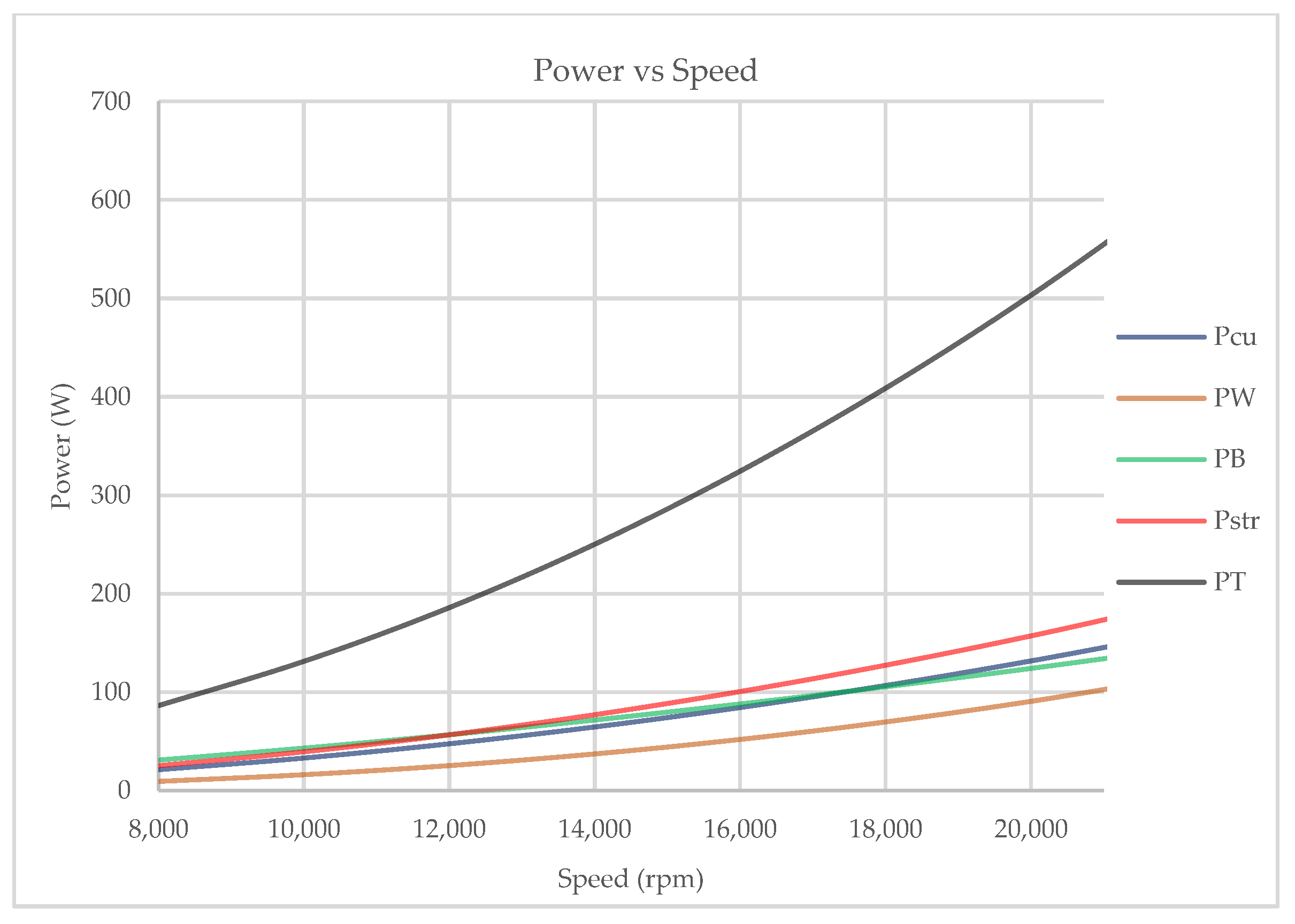
5. Calculation of Losses in FESS

The losses in a flywheel storage system are categorised as electrical (hysteresis, eddy current, copper), mechanical (drag, bearing friction), and power converter related (conduction and switching) [59]. Neglecting the conduction and switching losses, the power balance equations, including the mentioned losses, are as follows:
P i n = P o u t + P l o s s P i n = P o u t + P c u + P c o r e + P r e + P m e c h P i n = P o u t + P c u + P c o r e + P r e + P b + P w
where P c u is the copper loss, P c o r e is the iron loss, P r e is the rotor eddy current loss, and P m e c h is the mechanical loss due to windage loss P w and bearing friction loss P b .

5.1. Copper Loss

Copper loss, which is also referred to as resistance loss or joule loss, is calculated using the winding resistance R s (Ω) and stator current i a ( A ) [60].
P c u = 3 i a 2 R s
Since voltage and angular speed are linearly related [61], Equation (11) can be represented as a function of the angular speed ω   ( rad s ) and voltage constant K e   ( V . s rad )   .
P c u = 3 ( K e   ω / 2 ) 2 R s

5.2. Mechanical Losses
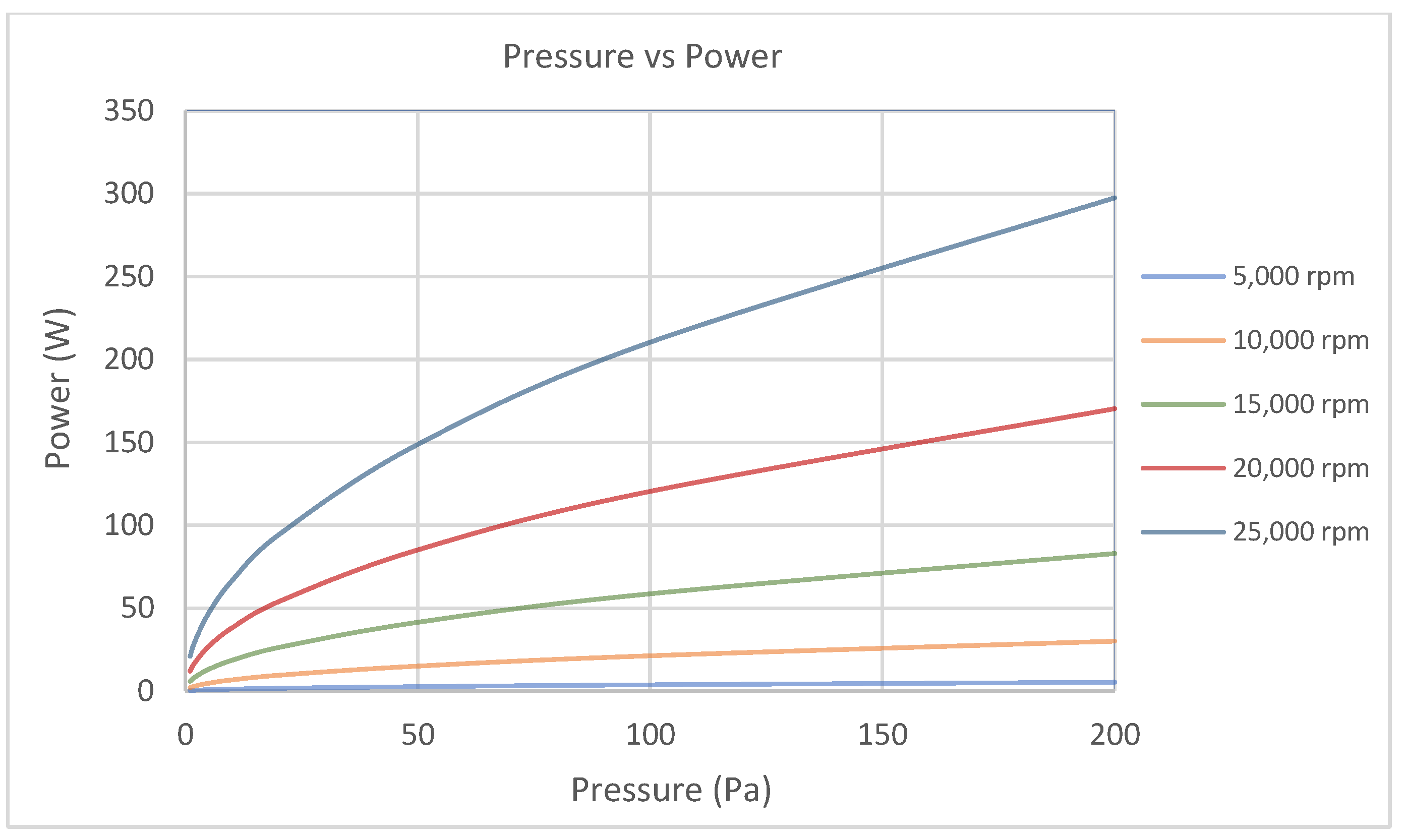
Mechanical loss in a FESS is mainly due to windage and bearing friction losses. The former is due to the friction between the rotating flywheel rotor and surrounding gas or air, depending on the type of enclosure. Windage loss is proportional to the cube of speed, and hence, it becomes significant when the rotor speed is increased, as shown in Equation (13) [60]:
P W = 1 64 C M ρ ω 3 ( D r o 5 D s 5 )
where C M is the torque coefficient, ρ is the coolant density (kg/m3), D r o is the rotor outer diameter (m) and D s is the shaft diameter (m). The torque coefficient is dependent on coolant viscosity, speed and size of the rotating disc. The increase in velocity changes the flow type of a rotating disc in a medium from laminar to turbulent. This transition is determined by Reynolds number 3 × 10⁵, a dimensionless parameter calculated using Equation (16).
C M = 3.87 R e 1 2 R e < 3 × 10 5
R e = ρ ω D r o 2 4 μ
where R e is the Reynolds number and μ is the dynamic viscosity of the coolant (kg/m·s). C M is calculated using Equations (14) or (15), depending on the size of the Reynolds number.
Predicting bearing torque and power loss of bearing through analytical models is complex and still limited in accuracy in some applications. This is due to the level of difficulty associated with satisfactorily quantifying the relationship between the state of lubricant within the bearing cavity and the applied lubricant conditions. Practical experience shows that increase in amount of lubricant will generally increase the bearing friction, and hence, the torque. Although some percentage of it can be accounted for by some of the lubricant filling the bearing cavity, the relationship of this parameter to the quantity of lubricant supply still needs to be empirically determined [62]. Therefore, empirical methods proposed by bearing manufacturers, such as SKF and NSK, are usually considered for estimating bearing torque and power loss of a FESS.
The torque of a rolling bearing consists of two components, one speed dependent T v , the other load dependent T L [63]:
T B = T L + T v
The load term T L is determined by bearing type and load:
T L = f L F B D p
where F B is the load applied on the bearing (N), D p is the pitch circle diameter of the rolling element (m), and f L is a factor dependent on bearing design and relative load that can be obtained by
f L = z ( F s C s ) y
F s is the static equivalent applied load (N) determined using Equation (20) and C s is the static load rating of the bearing (N) given in the manufacturer’s catalogue, Table 3.
F s = X s F r + Y s F a
where F r is the radial load (N), F a is the axial load (N), X s and Y s are radial and axial load factors, and z and y are load torque factors determined experimentally. These factors are provided by the bearing manufacturers and are given in Table 4.
The speed dependent component of the bearing torque is determined by oil viscosity and speed of the bearing:
T v = f 0 ( v 0 n ) 2 3 D p 3
where n is the bearing speed (rpm), v 0 is the kinematic oil viscosity (centistokes) and f 0 is a factor depending the bearing type and mode of lubrication, and is given in Table 4.

5.3. Other Losses

Calculating core losses and eddy current losses of the electrical MG is not easy as they are produced under load conditions and require experimental measurements. A theoretical measurement of the combination of eddy current losses in electrical machine conductors, iron core, and other metallic parts, due to flux leakages, is referred to as stray load losses [64]. It can be calculated in terms of stator dq currents i d and i q , and angular speed ω , as shown in Equation (22) [65]. However, the stray loss constant C s t r needs to be determined experimentally.
P s t r = C s t r ω 2 ( i d 2 + i q 2 )
An approximation of the stray losses can be calculated based on IEEE standard expression in terms of the generated power P G and rated power P R :
P s t r = 0.005 P G 2 P R
As stray loss is produced in the electrical machine, the rated power P R and electromagnetic torque T e (N·m) of the PMSM is used to derive this expression in terms of the angular speed ω .
For the calculation of losses in PMSM-Flywheel unit the following assumptions were made:
  • The clearances between stationary and rotating components is small, such that the boundary layers on stationary and rotating surfaces merge.
  • The flywheel rotor is assumed to be a drum type steel laminated cylinder.
  • The windage losses are calculated under maximum pressure conditions of 100 Pa at 40 °C and maximum speed of 20,000 rpm.
  • Density values are calculated from temperature and pressure using ideal gas law.
  • Windage on the motor–generator is neglected, since its rotor diameter is much smaller than that of the main rotor, and the power law on diameter for windage is 5.
  • Switching loss and IGBT conduction loss in power converters are neglected as these losses are small compared to other losses in a FESS. Although, this might not be the case in some other storage systems, where they may need to be considered.
  • It is assumed that the combined axial load on the bearing is 10% of the total flywheel rotor weight with the rest taken by the passive magnetic bearing.
The parameters and coefficients of the flywheel unit are given in Table 5. Substituting the dynamic viscosity ( μ ) and coolant density ( ρ ) in Equation (16) gives a Reynolds number of approximately 4890, and therefore Equation (14) can be used to calculate the torque coefficient ( C M ) .
Substituting (14) and (16) in (13) gives windage losses as a function of the flywheel speed.
P W = 0.121 ρ μ ω 5 D r o ( D r o 5 D s 5 )
Equation (13) can be reduced further by substituting ρ ,   μ ,   D r o and D s parameters from Table 5:
P W = 4.51 × 10 7   ω 5 2
Power loss due to bearing friction is calculated by selecting a single row radial bearing with grease type of lubrication method. Substituting the relevant parameters from Table 5 into Equation (17) gives
P B = 0.01 ω + 2.67 × 10 4   ω 5 3  
Similarly, copper and stray losses are calculated by substituting the parameters and coefficients in Equations (12) and (23):
P c u = 3 × 10 5   ω 2
P s t r = 3.58 × 10 5   ω 2
The derived equations show that the windage loss is proportional to ω 5 2 , the significant term in the bearing loss is proportional to ω 5 3 , and copper and stray losses are proportional to the square of the angular speed.

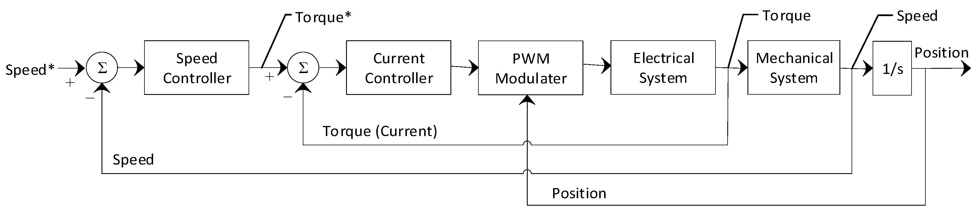
6. Analysis and Control of FESS

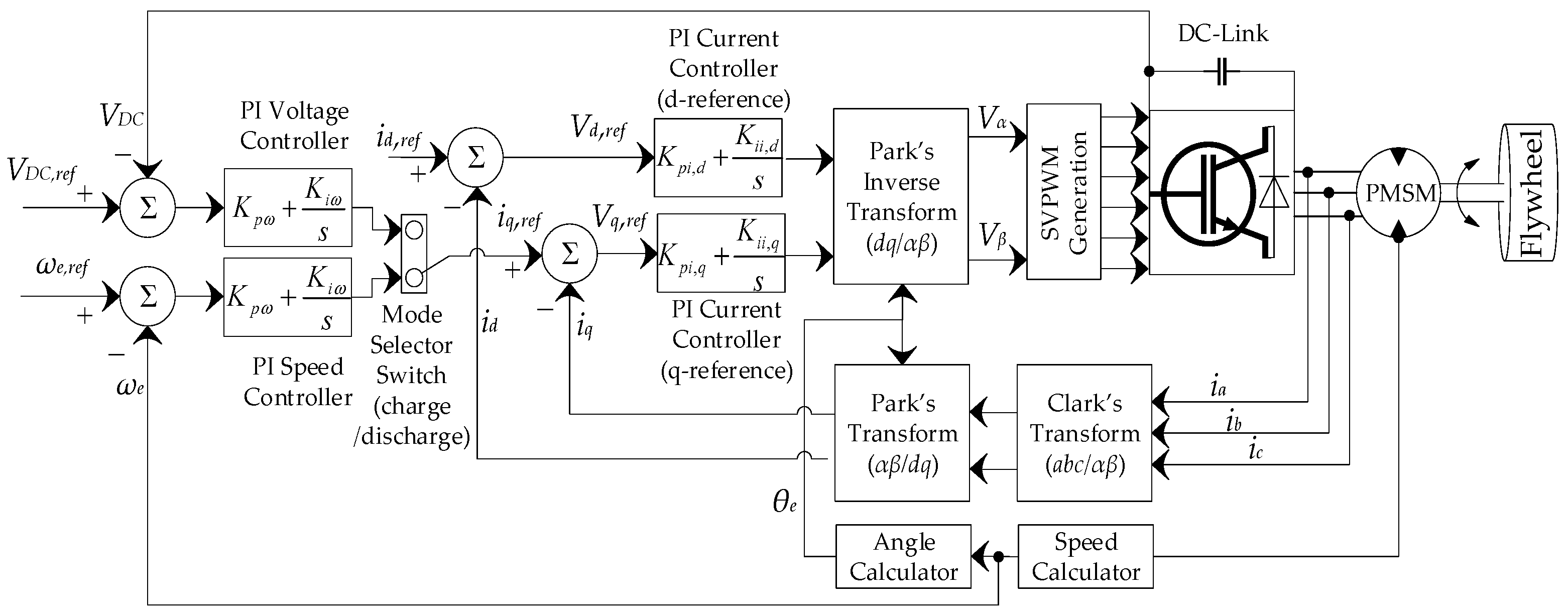
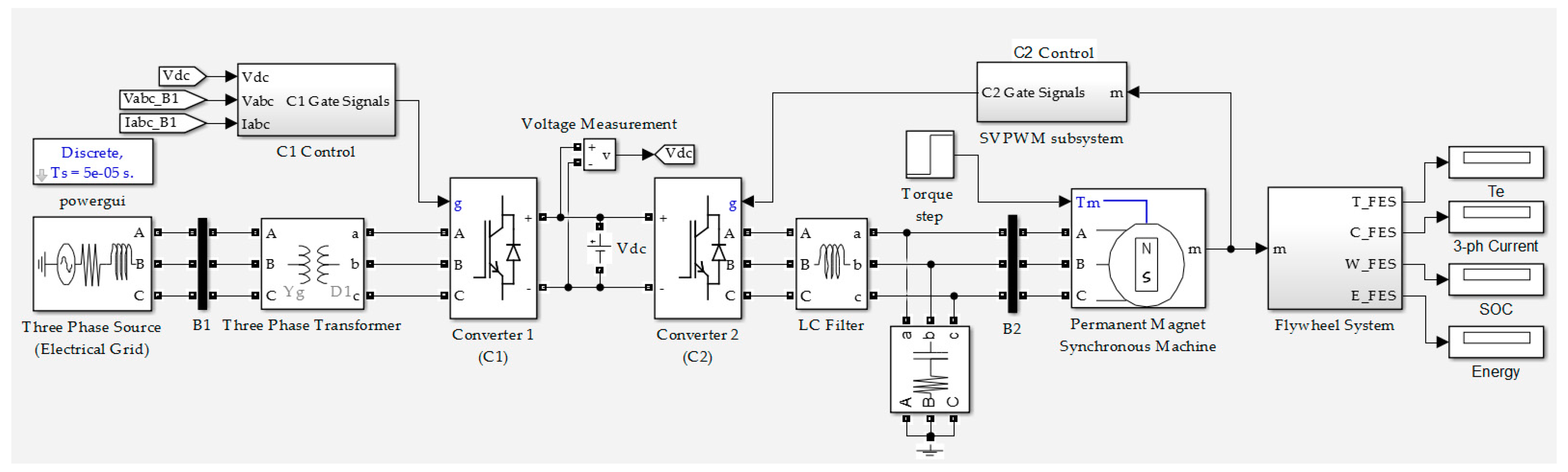
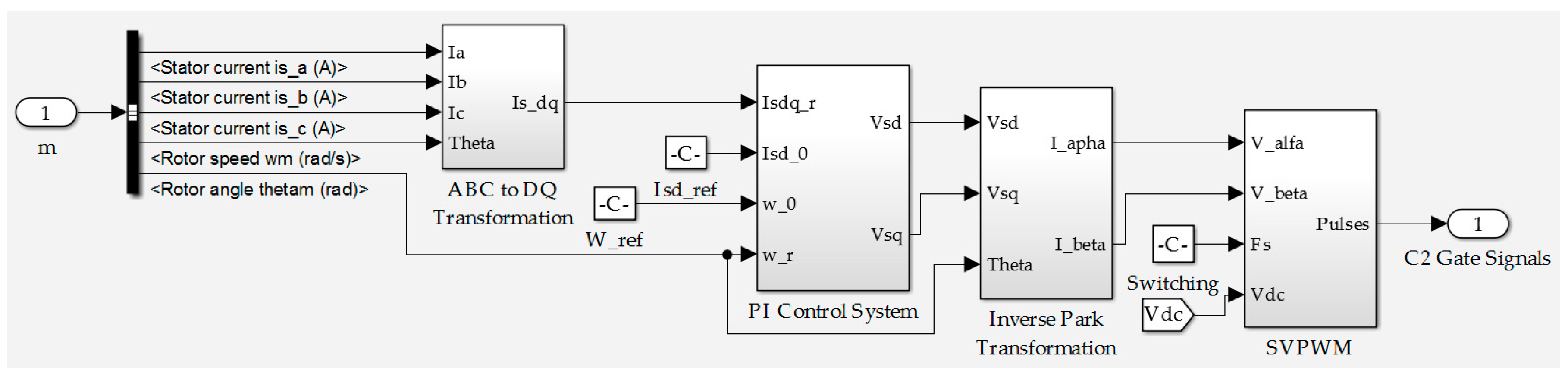
6.1. System Configuration and Mathematical Model

The general structure of FESS studied in this paper is as shown in Figure 1. The flywheel rotor is integrated with a MG to support the electrical energy conversion. The integrated MG is controlled by a bidirectional converter, which can operate as an inverter to charge the flywheel, or as a rectifier to discharge the flywheel. The flywheel and the MG are connected coaxially, thus controlling the MG, and the converter enables control of the FESS. The MG is a PMSM which is widely used in motion control applications due to its high performance, compact structure, high power density, high steady state torque density, and high efficiency. It maximises the performance in applications where variable speed is required [66]. For the same rating, PMSM has a higher power density to that of an induction motor. Due to its simple method of control, lower mass and low losses, PMSM has been broadly used in numerous applications in recent years [67,68,69,70,71]. The operation of the PMSM-Flywheel is controlled using proportional-integral (PI) cascaded control structure. The controller is designed to follow the changes in position, speed, and torque of the machine to a set of reference values. Due to its flexibility, it is widely used in industry to control the position and velocity of AC motor drives. It generally consists of segregated control loops with the outermost position loop followed by the inner speed loop, and the innermost current (torque) loop as shown in Figure 3. This technique requires the response time of the current loop to be the fastest compared to the speed and position loops [72]. Flywheel applications do not require the position loop, since the main objective is to control the state of charge based on information from the speed feedback loop. However, in the proposed system, the position loop provides the position angle information, which is required to generate waveforms and calculate the feedback d-q axis currents to control the flux and torque of FESS independently.
To determine the parameters of the PI controller, the mathematical equations of PMSM are derived in the rotor d-q reference frame as presented in Equations (29–31) [61]. Transforming the three-phase voltage and current equations of the PMSM into two-phase d-q system eases the analysis and control of the machine. Conversion of a three-phase system to a two coordinate d-q reference frame system is performed using Clark’s and Park’s transform [73]. This allows determination of the controller constants in terms of machine parameters. Detailed description of the PI controller design for PMSM is described in [74,75,76].
V q = R s I q + L q d I q d t + ω e L d I d + ω e λ m
V d = R s I d + L d d I d d t ω e L q I q
Similarly, the torque developed by the motor is given as:
T e =   3 2 P 2 λ m I q + ( L d L q ) I d I q )
The mechanical torque is represented by:
T e = J d ω m d t + B ω m + T L  
where, I d = Direct axis stator current in ampere (A); I q = Quadrature axis stator current in ampere (A); R s = Stator resistance in ohms (Ω); L d = Direct axis inductance in henry (H); L q = Quadrature axis inductance in henry (H); J = Moment of inertia in kg·m2; B = Friction of viscous in N·m/rad/s; P = Number of poles; λ m = Rotor flux constant in V/rad/s; ω e = Rotor’s electrical speed in rad/s; T L = Load torque in N·m; T e = Electromagnetic torque in N·m; ω m = Rotor’s mechanical speed in rad/s.
The model of the PMSM-Flywheel system is implemented with the help of Equations (1)–(6) of the flywheel, and Equations (29)–(32) for a surface mounted PMSM using the control method mention above. A detailed description and different controlling techniques of PMSM are discussed in references [77,78,79].

6.2. System Operation and Control Strategy
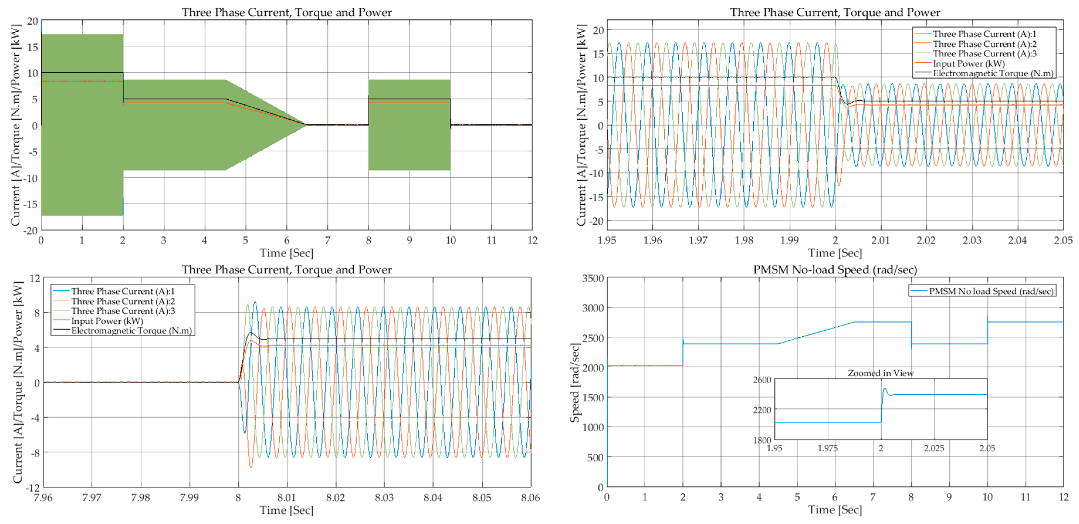
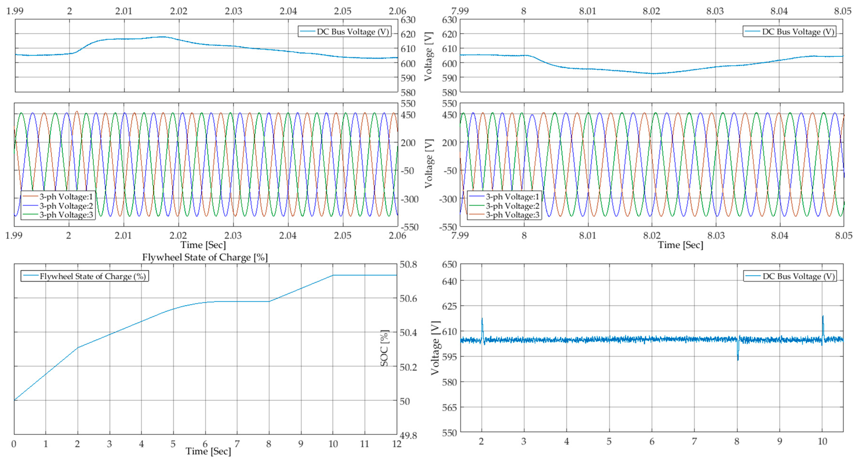
A simplified topology of the FESS connected to an electrical supply with a bi-directional power flow is shown in Figure 4. The FESS and the grid are connected through a DC-link with the help of converters. Converter 1 (C1) is to control the power flow from/to the grid and converter 2 (C2) is for controlling the MG. The working principle of the FESS can be discussed in three modes of operation: charging mode, discharging mode, and standby mode. During charging, C2 draws power from the DC-link to run the MG and accelerate the flywheel. MG is operating as a motor, C2 as an inverter, and C1 as a rectifier to maintain the DC voltage fixed. While discharging, the operation of both converters is inverted, and the flywheel is decelerating to maintain the DC-link voltage by drawing energy from the flywheel. The standby mode is when the flywheel spins at an optimum speed and no energy conversion occurs.
The system charging control is performed based on field oriented control (FOC) using space vector pulse width modulation (SVPWM) [80]. FOC, also referred to as vector control, is one of the controlling methods for variable speed drives, particularly those using permanent magnets. The method enables controlling of the torque and flux of the three phase AC motors by controlling the current. The three phase system is transformed into a two coordinate (dq) time invariant system that allows decoupled control of torque and flux of PMSM, similar to a DC machine [41,66,81]. SVPWM is used for controlling and switching the gates of the inverter semiconductors to produce a smooth output waveform [78,80].
The control block of the PMSM-Flywheel in both charging and discharging states is represented in Figure 5. The system is controlled by an inner current loop and an outer speed/voltage loop using PI controllers. In the inner control loop the three phase stator currents are measured and transformed to two phase “dq” currents using the Clark–Park transformation. The decoupled “dq” currents are controlled separately, with PI current controllers to control flux and torque. The d-component of the current is the flux producing component, and q-component is the torque producing component [82]. Similarly, in the outer loop, the PMSM speed is measured and regulated by comparing it with the reference speed. The output of the speed PI regulator is applied as the reference q-current component for the current PI regulator to control the torque accordingly.
During discharge, when the DC-bus voltage drops below a threshold value, a voltage controller is used to adjust and control the system current to keep the DC-link voltage fixed. The outer speed loop in charging mode is replaced with the outer voltage loop in discharging mode. Similar to the motoring mode where the speed is regulated by the extracting energy from the source, the generating mode allows the DC-link voltage to be measured and regulated by comparing it with the reference voltage. The output of the voltage PI controller is regulated as an input for the current PI controller.
As the FESS operates between a minimum and maximum speed range for better utilisation of its useful energy, the speed loop is required to determine and monitor the flywheel’s state of charge. The status of the rotor speed and position in any state of operation is essential for controlling flywheel’s torque and flux, in order to operate within the specified speed range. On the other hand, the DC bus voltage can be maintained by controlling the power from the PMSM and hence its torque, provided that the motor speed is known.
Based on the control strategy explained, the FESS model is implemented in the MATLAB/SIMULINK environment as shown in Figure 6. The interconnected DC-bus is supplied by either the electrical grid or the flywheel system, depending on whether the system is in charging or in discharging state. The inverter for PMSM-Flywheel is controlled using SVPWM, as represented in Figure 7. The rectifier switching is controlled through another feedback loop from the AC supply and the DC-bus voltage. An LC filter is connected at the output of the inverter to reduce the current ripples and smooth out the inverter output waveform.

7. Results Analysis

7.1. System Losses

The parameters of the simulated high inertia FESS are presented in Table 5. Combined losses due to windage, bearing friction, winding resistance and stray losses are calculated as described in Section 5. Figure 8 shows the relationship between power loss of the system and angular speed due to aforementioned losses.
The drag and bearing friction loss curves indicate variation of losses, due to speed variations under constant temperature (40 °C) and pressure (100 Pa) conditions. Under these conditions, the mechanical loss is 214 W, which accounts for approximately 75% of the total system losses. However, these losses will be much smaller under normal conditions, since the flywheel will be enclosed in a vacuum chamber, and temperature would hardly reach 40 °C. Figure 9 shows combined total power loss and other losses as a function of angular velocity.
The effect of pressure on mechanical loss is significant for high speed applications. Figure 10 shows windage loss as a function of pressure for five different operating angular velocities. It indicates that for higher speeds (15,000 rpm and beyond) the pressure needs to be kept at a lower level to limit the losses at an adequate level. To achieve lower than 100 W at 20,000 rpm, a pressure of less than 75 Pa needs to be reached, leaving a maximum of 124 W for bearing loss. For the same amount of loss, the pressure must be further reduced to approximately less than 20 Pa, if the flywheel is operating at 25,000 rpm.

7.2. Simulated Results

The system dynamic analysis is performed on different states of charging and discharging for a total duration of 35 min. In the charging mode, energy is stored by applying a constant torque to charge the flywheel to the desired speed. In discharge mode, the stored energy is extracted by reversing the applied torque to slow down the flywheel. The charge–discharge speed range is set to 10,000–20,000 rpm with the flywheel system modelled to store 5 kWh of usable energy within this operating range. The reference value for the DC-bus voltage is set to 600 V, which is maintained by the AC supply during charging and by the PMSM-Flywheel during the discharging state.

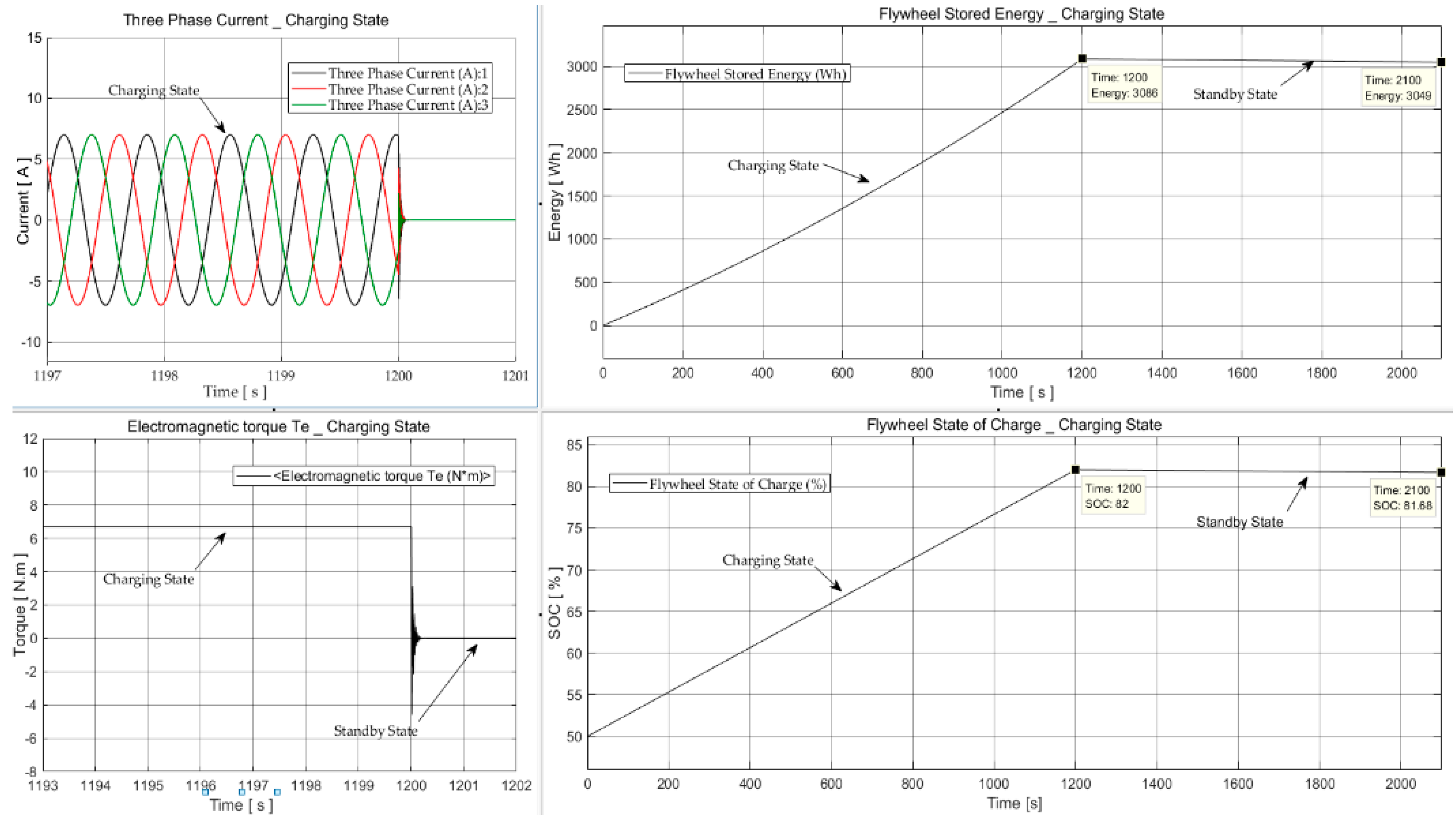
7.2.1. Charging State

The charging state is simulated by applying a constant 6.7 N·m accelerating torque for a duration of 20 min to accelerate the flywheel from an initial charge of 50% and a starting speed of 10,000 rpm. FESS electromagnetic torque (N·m), three-phase current (A), percent state-of-charge (SOC) and stored energy (Wh) are shown in Figure 11.
The system continues charging for 20 min (1200 s), and then switches to standby mode for another 15 min. At the instant the accelerating torque is removed ( T = 0   N · m ) , the three-phase current drops to zero (A), and the flywheel SOC and stored energy switch to standby mode (Figure 11). During the first 20 min of charging, the flywheel is 82% charged and stores more than 3 kWh of energy. In contrast, during the standby mode, the system loses approximately 37 Wh, which accounts for 1.2% of the stored energy. These losses are due to bearing friction and aerodynamic drag, whereas copper and stray losses are not contributing during standby mode.

7.2.2. Discharging State

The discharge mode is simulated for the case when the FESS is initially fully charged and a load torque ( T = 6.7   N · m ) is applied to extract energy from the system for a duration of 15 min (Figure 12 and Figure 13). At the instant when the torque is applied, the three-phase current increases, while the stored energy and SOC start falling. The FESS delivers energy by regulating the flywheel speed and maintaining the DC-bus voltage. The system dynamic response is tested by instantly switching the flywheel to charging mode for another 5 min. Figure 12 shows the system responsiveness and compliance of the current and torque at t = 900   s and t = 1200   s . At the last stage, the system returns to standby mode for 15 min. Compliance of the flywheel speed and stored energy for each state is shown in Figure 13.
During the discharge mode, 25% of the total charge is reduced, and approximately 2.93 kWh is extracted from the system (Figure 13). The self-discharge or system standby loss is approximately 1.25% of the total stored energy during the first 20 min. This indicates that the flywheel will lose nearly 70 Wh if left at standby mode for 30 min; although, it can store or deliver 5 kWh of energy during the same period if an accelerating torque or load torque is applied.

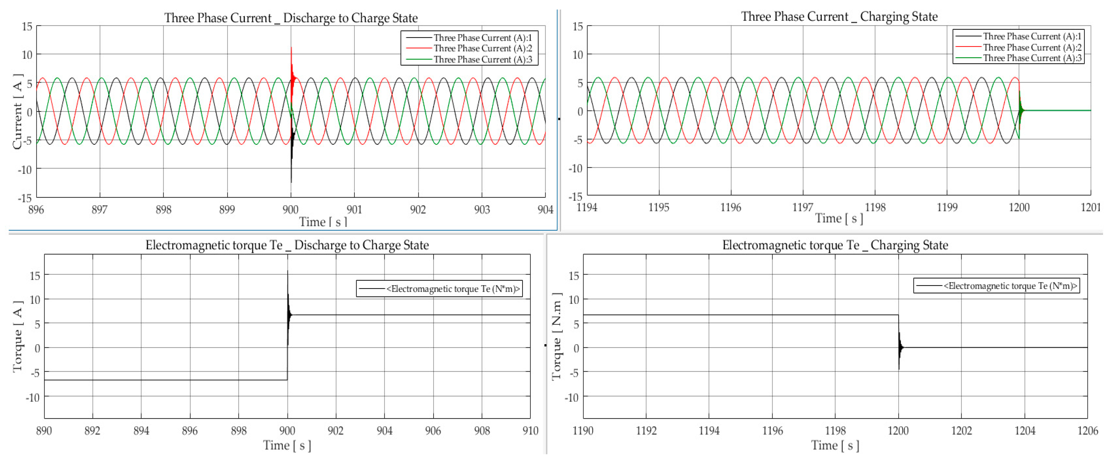
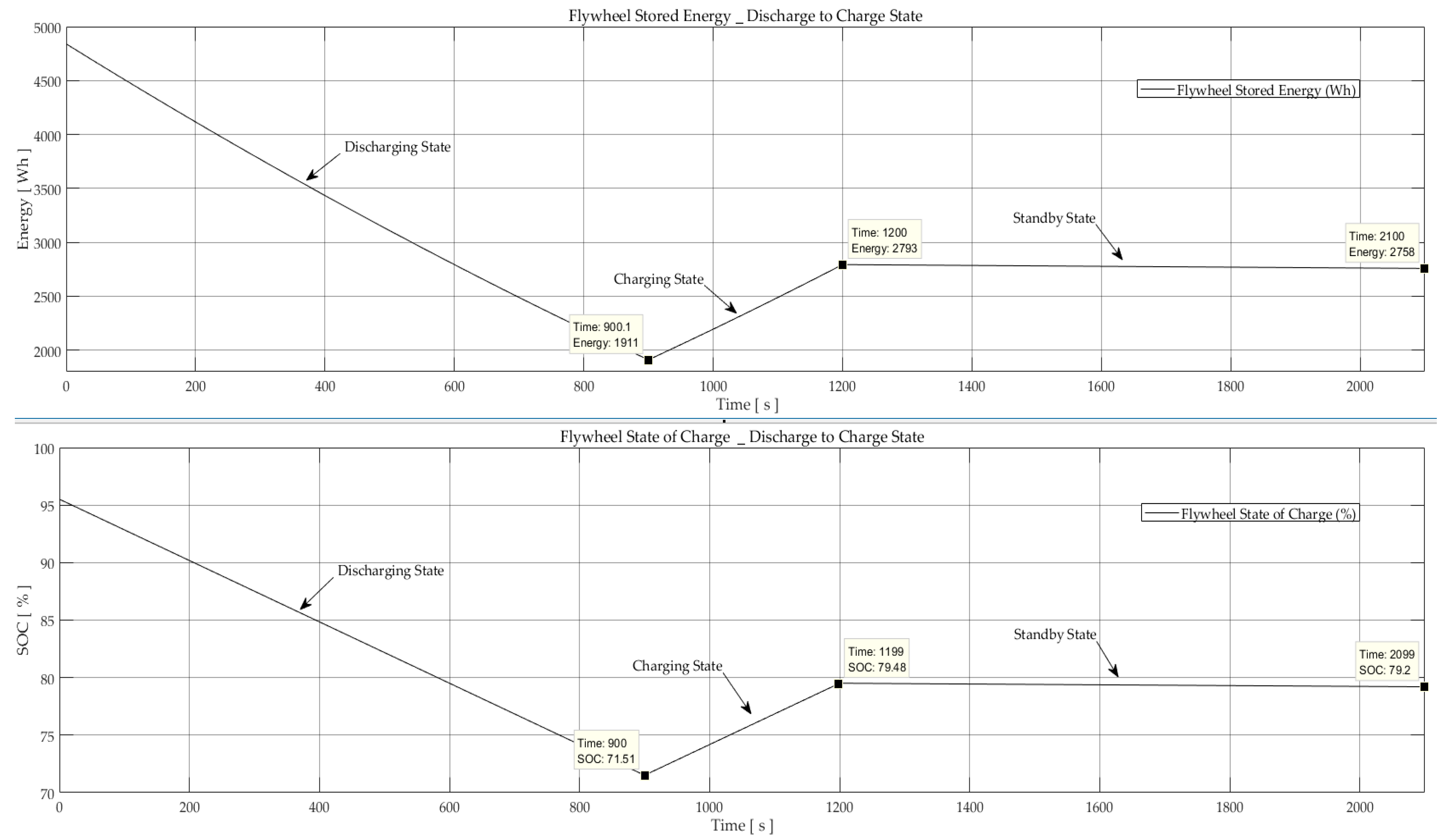
7.2.3. Charge–Discharge State

In this state, the system is tested for real life scenarios where it switches between charging, discharging, and standby modes. The analysis of simulations is performed for a short duration of 12s so the timescale is sufficient to capture the most important effects and show the system responsiveness. In each case, the system is tested for sudden and gradual load changes and waveforms of the PMSM-Flywheel torque, three-phase current and voltage, SOC, and DC-bus voltage are plotted (Figure 14 and Figure 15). The torque, current and power waveforms are plotted on the same axis for better comparison.
The torque is initially at T = 10   N · m , indicating that the flywheel is charging, and the DC-bus is supplying the FESS. At t = 2   s it is reduced to T = 5   N · m , but the FESS is still charging at a constant rate. At t = 4.5   s , the charging is slowed down gradually until the flywheel switches to standby mode at t = 6.5   s . The system starts to charge again at t = 8   s and continue for 2 s before switching back to standby state. Due to higher rotational speed of the PMSM-Flywheel rotor, the three-phase current waveforms are not visible for analysis, and hence, the zoomed in views at t = 2   s and t = 8   s are shown in Figure 14.
The speed waveform of the electrical machine at no-load condition (flywheel not connected) is also shown in Figure 14. The PMSM speed follows the torque, and accelerates when the torque is reduced ( t = 2   s   &   4.5   s ), and slows down when the torque increases at t = 8   s .
The inverter output voltage, DC-bus voltage, and SOC of FESS are presented in Figure 15. The DC-bus voltage fluctuates between ±3% of the rated voltage during the step changes at t = 2 ,     8 ,   &   10   s . It rises to 620 V when the torque is reduced, whereas it drops to 590 V when the torque is increased. This is due to sudden torque changes; however, these voltage variations only last for approximately 45 ms. Except during the load torque changes, the voltage output and DC-bus voltage are stable, and the flywheel charging variations follow the load when switching between different charging states.

7.2.4. Discussion

The simulated results indicate the response of the FESS model for charging, discharging, and standby states. The flywheel system stores 5 kWh of energy within a speed range of 10,000–20,000 rpm, and an accelerating torque of 6.7 N·m. During the standby state, when no torque is applied on the system, the calculated self-discharge energy losses are about 1.25% of the total stored energy. This is due to the system losses, and especially mechanical losses, which create friction torque, and hence, loss of stored kinetic energy. The total standby energy losses during 30 min has been approximately 70 Wh. For the same period and considering a fully charged flywheel with a maximum speed of 20,000 rpm, the friction torque will reduce its speed to 19,600 rpm. This gives 5% loss of energy per hour, and adding copper and stray losses will give an overall roundtrip efficiency of 88%. To reduce the run-down losses of the system, use of a passive magnetic bearing has been used to levitate most of the weight, and the axial load on the ball bearing system will be very light, leading to low friction and high life. Rotor drag loss can be mitigated by enclosing the flywheel in a vacuum chamber with only occasional re-pumping requirements due to the lower speed of the system. Electromagnetic drag on the rotor is another area of concern, but this can be kept low by use of low iron loss materials.
The analysis of simulations was also performed for a short duration of 12 s, to indicate the most important effects and dynamic response of the system for real life scenarios. It is shown that sudden step changes in load torque renders corresponding variations in charging characteristics and stored energy of the flywheel system. By contrast, the bidirectional converters at the machine side and the grid side control the operation of the PMSM-Flywheel and, regardless of the mode of operation, a stable DC-bus voltage is maintained. The fluctuation of the DC-bus voltage due to load instabilities is limited to 3%, which is recovered within 40–45 ms. Conformation of the flywheel speed and power with respect to torque variations indicates a favourable system responsiveness and dynamic performance for each state.
Compliance of the simulated results imply that the model can be further explored to analyse performance a PMSM-Flywheel integrated to a power system providing energy backup. This is an area with very limited experimental data available, since the majority of grid connected flywheel systems are used for high power applications providing power quality and ride through services. Another widely unexplored scenario would be operation of a flywheel system providing longer duration energy storage backup in an isolated power system in the presence of renewables such as solar photovoltaic system. Application of FESS providing frequency improvement services for wind and solar PV systems is previously addressed in the literature, but its operation as a stand-alone energy storage option still remains unexplored. The software tool explored in this work can be modified accordingly to test and analyse numerous real-life scenarios for such systems. For example, this can be a grid connected FESS charged once or two times daily for energy saving purposes, or a hybrid flywheel and diesel generator in a solar PV system with the flywheel providing energy backup to reduce diesel generator involvement.

8. Conclusions

This paper has presented a methodology for modelling an electrically driven flywheel based on a PMSM controlled by back to back converter topology. The components and structure of the FESS are introduced, and its characteristics and main applications are briefly discussed. Flywheels offer the unique characteristics of very high cycle and calendar life, and are the best storage technology for applications demanding these requirements. High power capability, instant response with high round trip efficiency, and ease of recycling, are its main attributes.
In this paper, calculation of the losses and efficiency of a proposed FESS is presented. The system losses were calculated by deriving the mathematical loss model of the FESS for extreme temperature and pressure conditions, which are hardly ever reached as the flywheel is operated in vacuum. The loss model included windage loss, bearing loss, copper loss, and stray loss, which is a combination of eddy current loss, iron core loss, and other metallic parts, due to flux leakages. It was shown that the mechanical losses account for 75% of the total losses, and to limit the losses to an acceptable level, the pressure needs to decrease below 75 Pa for 20,000 rpm. The results of the analysis also showed that the run-down energy loss of the FESS is approximately 37 Wh during 15 min of standby mode. It will lose about 5% of the total stored energy per hour if left in idle mode. Neglecting switching and conduction losses in power converters and windage losses on the motor–generator, the total efficiency of the system was more than 88%. The system under consideration was a high inertia flywheel for longer duration storage to accumulate 5 kWh within a speed range of 10,000–20,000 rpm. This is contrary to most of the flywheel systems in industry, usually performing short term high power applications. The choice of ratio of power to energy is a free design choice, one other benefit of the flywheels.
The dynamic performance and response of the system was tested when simulating the FESS for real life scenarios of charging and discharging states. The analysis results showed the characteristic performance and compliance of the load torque, SOC, input–output power, and three-phase current and voltage of the PMSM-Flywheel. The no-load speed of the PMSM was also plotted to show the system response when the flywheel rotor is not connected. It was shown that sudden step changes in torque develops corresponding changes in flywheel speed, as well as its SOC and stored energy. At the instant of load change, the DC-bus voltage fluctuations were within ±3% of the rated voltage, which was controlled and recovered within 40–45 ms.
Conformation of the simulated results implies responsiveness and validity of the software model. Modelling and simulation of a higher inertia flywheel for ground power applications is a new area which has not been widely explored due to unavailability of the experimental data. This software tool can be developed to analyse different scenarios for such applications. It can be considered as an initiative for future researchers exploring models to analyse PMSM assisted FESS for energy storage applications.
Future work will include modelling and analysis of an isolated solar photovoltaic system with a FESS providing backup power for islanded remote areas.

Author Contributions

All authors have contributed to the idea behind the work. M.E.A. and K.R.P. conceived and designed the experiments and M.E.A. performed the experiments. M.E.A and D.N. analysed the data, K.R.P. contributed his expertise in FESS as head of research group and D.N. contributed his expertise in Power Electronics. M.E.A. wrote the majority of the paper, whereas K.R.P. and D.N. made small contributions.

Conflicts of Interest

The authors declare no conflict of interest.

References

  1. Medina, P.; Bizuayehu, A.W.; Catalao, J.P.S.; Rodrigues, E.M.G.; Contreras, J. Electrical Energy Storage Systems: Technologies’ State-of-the-Art, Techno-economic Benefits and Applications Analysis. In Proceedings of the 47th Hawaii International Conference on System Sciences, Waikoloa, HI, USA, 6–9 January 2014; pp. 2295–2304. [Google Scholar]
  2. Chen, H.; Cong, T.N.; Yang, W.; Tan, C.; Li, Y.; Ding, Y. Progress in electrical energy storage system: A critical review. Prog. Nat. Sci. 2009, 19, 291–312. [Google Scholar] [CrossRef]
  3. Hadjipaschalis, I.; Poullikkas, A.; Efthimiou, V. Overview of current and future energy storage technologies for electric power applications. Renew. Sustain. Energy Rev. 2009, 13, 1513–1522. [Google Scholar] [CrossRef]
  4. Del Granado, P.C.; Wallace, S.W.; Pang, Z. The value of electricity storage in domestic homes: A smart grid perspective. Energy Syst. 2014, 5, 211–232. [Google Scholar] [CrossRef]
  5. Fu, B.Q.; Hamidi, A.; Nasiri, A.; Bhavaraju, V.; Krstic, S.B. The Role of Energy Storage in a Microgrid Concept. IEEE Electrification Mag. 2013, 1, 21–29. [Google Scholar] [CrossRef]
  6. Vafakhah, B.; Masiala, M.; Salmon, J.; Knight, A. Emulation of flywheel energy storage systems with a PMDC machine. In Proceedings of the 18th IEEE International Conference on Electric Machines, Vilamoura, Portugal, 6–9 September 2008; pp. 1–6. [Google Scholar]
  7. Liu, H.; Jiang, J. Flywheel energy storage—An upswing technology for energy sustainability. Energy Build. 2007, 39, 599–604. [Google Scholar] [CrossRef]
  8. Hebner, R.; Beno, J.; Walls, A. Flywheel batteries come around again. IEEE Spectr. 2002, 39, 46–51. [Google Scholar] [CrossRef]
  9. Bolund, B.; Bernhoff, H.; Leijon, M. Flywheel energy and power storage systems. Renew. Sustain. Energy Rev. 2007, 11, 235–258. [Google Scholar] [CrossRef]
  10. Sebastián, R.; Alzola, R.P. Flywheel energy storage systems: Review and simulation for an isolated wind power system. Renew. Sustain. Energy Rev. 2012, 16, 6803–6813. [Google Scholar] [CrossRef]
  11. Emadi, A.; Nasiri, A.; Bekiarov, S.B. Uninterruptable Power Supplies and Active Filters; Illinois Institute of Technology: New York, NY, USA; CRC Press: Washington, DC, USA, 2005. [Google Scholar]
  12. U.S Department of Energy (DOE/EE), Flywheel Energy Storage. An Alternative to Batteries for Uninterruptible Power Sypply Systems; U.S Department of Energy (DOE), Energy Efficiency and Renewable Energy: Washington, DC, USA, 2003.
  13. Bender, D. Flywheels; Sandia Report, SAND2015-3976; Sandia National Laboratories: Livermore, CA, USA, 2015.
  14. Tesla Power Wall. Available online: https://www.tesla.com/en_GB/energy?redirect=no (accessed on 1 November 2017).
  15. Brakels, D. Tesla Quietly Release New Powerwall Warranty: But There’s One Big Problem…. Available online: https://www.solarquotes.com.au/blog/new-powerwall-warranty/ (accessed on 8 November 2017).
  16. Kailasan, A.; Dimond, T.; Allaire, P.; Sheffler, D. Design and Analysis of a Unique Energy Storage Flywheel System—An Integrated Flywheel, Motor/Generator, and Magnetic Bearing Configuration. J. Eng. Gas Turbines Power 2015, 137, 1–10. [Google Scholar] [CrossRef]
  17. Tang, C.; Yang, J.; Han, D.; Lei, H. Rotor dynamics research of the composite flywheel spin test system: Modeling and simulation. In Proceedings of the 2016 IEEE International Conference on Power and Renewable Energy (ICPRE), Shanghai, China, 21–23 October 2016; pp. 537–541. [Google Scholar]
  18. Zhang, K.; Dai, X.; Zhang, X. Dynamic Analysis and Control of a n Energy Storage Flywheel Rotor with Active Magnetic Bearings. In Proceedings of the 2010 International Conference on Digital Manufacturing and Automation (ICDMA), Changsha, China, 18–20 December 2010. [Google Scholar]
  19. Mao, C.; Zhu, C. Vibration control for active magnetic bearing rotor system of high-speed flywheel energy storage system in a wide range of speed. In Proceedings of the 2016 IEEE Vehicle Power and Propulsion Conference (VPPC), Hangzhou, China, 17–20 October 2016. [Google Scholar]
  20. Zhang, C.; Tseng, K.J. A novel flywheel energy storage system with partially-self-bearing flywheel-rotor. IEEE Trans. Energy Convers. 2007, 22, 477–487. [Google Scholar] [CrossRef]
  21. Zhang, C.; Tseng, K.J. Design and control of a novel flywheel energy storage system assisted by hybrid mechanical-magnetic bearings. Mechatronics 2013, 23, 297–309. [Google Scholar] [CrossRef]
  22. Genta, G. Kinetic Energy Storage: Theory and Practice of Advanced Flywheel Systems; Butterworth Heinemann Ltd.: London, UK, 1985. [Google Scholar]
  23. Shelke, P.R.S.; Dighole, D.G. A Review paper on Dual Mass Flywheel system. Int. Res. J. Eng. Technol. 2016, 5, 326–331. [Google Scholar]
  24. Östergård, R. Flywheel Energy Storage—A Conceptual Study; Uppsala Universitet: Uppsala, Sweden, 2011. [Google Scholar]
  25. Technology, F. Flywheel technology past, present, and 21st century projections. In Proceedings of the 32nd Intersociety Energy Conversion Engineering Conference, Honolulu, HI, USA, 27 July–1 August 1917; pp. 2312–2315. [Google Scholar]
  26. Pena-Alzola, R.; Campos-Gaona, D.; Martin, O. Control of Flywheel Energy Storage Systems as Virtual Synchronous Machines for Microgrid. In Proceedings of the 2015 IEEE Control Model Power Electronic, Vancouver, BC, Canada, 12–15 July 2015; pp. 1–7. [Google Scholar]
  27. De Oliveira, J.G. Power Control Systems in a Flywheel Based All-Electric Driveline; Uppsala Universitet: Uppsala, Sweden, 2011. [Google Scholar]
  28. Parfomak, P.W. Energy Storage for Power Grids and Electric Transportation: A Technology Assessment; Congressional Research Services: Washington, DC, USA, 2012.
  29. Akhil, A.A.; Huff, G.; Currier, A.B.; Kaun, B.C.; Rastler, D.M.; Chen, S.B.; Cotter, A.L.; Bradshaw, D.T.; Gauntlett, W.D. DOE/EPRI 2013 Electricity Storage Handbook in Collaboration with NRECA; Department of Energy (DOE): Washington, DC, USA, 2013.
  30. Su, W.; Jin, T.; Wang, S. Modeling and Simulation of Short-term Energy Storage: Flywheel. In Proceedings of the 2010 International Conference on Advances in Energy Engineering Modeling (ICAEE), Beijing, China, 19–20 June 2010; pp. 9–12. [Google Scholar]
  31. Meng, Y.M.; Li, T.C.; Wang, L. Simulation of controlling methods to flywheel energy storage on charge section. In Proceedings of the Electric Utility Deregulation and Restructuring and Power Technologies, Nanjing, China, 6–9 April 2008; pp. 2598–2602. [Google Scholar]
  32. Guo, Z.; Mu, X.; Bai, Z.; Cao, B. Research on the control of flywheel battery. J. Appl. Sci. 2007, 7, 3312–3316. [Google Scholar]
  33. Zhang, X.; Yang, J. An improved discharge control strategy with load current and rotor speed compensation for high-speed flywheel energy storage system. In Proceedings of the 17th International Conference on Electrical Machines and Systems (ICEMS), Hangzhou, China, 22–25 October 2014; pp. 318–324. [Google Scholar]
  34. Samineni, S.; Johnson, B.K.; Hess, H.L.; Law, J.D. Modeling and Analysis of a Flywheel Energy Storage System with a Power Converter Interface. In Proceedings of the International Conference on Power Systems Transients, New Orleans, LA, USA, 28 September–2 October 2003; Volume 4, pp. 1–6. [Google Scholar]
  35. Pena-Alzola, R.; Sebastián, R.; Quesada, J.; Colmenar, A. Review of Flywheel based Energy Storage Systems. In Proceedings of the 2011 International Conference on Power Engineering, Energy and Electrical Drives, Malaga, Spain, 11–13 May 2011. [Google Scholar]
  36. Gyrotricity Durable Energy Storage. High Speed, High Power Flywheel made from Low Cost Laminated Steel. Available online: https://www.gyrotricity.com/ (accessed on 5 January 2018).
  37. Sanders, S.; Senesky, M.; He, M.; Chiao, E. Low-Cost Flywheel Energy Storage Demonstration; Energy Research and Development Division, Final Project Report; Amber Kinetics, Inc.: Union City, CA, USA, 2015. [Google Scholar]
  38. Amiryar, M.; Pullen, K. A Review of Flywheel Energy Storage System Technologies and Their Applications. Appl. Sci. 2017, 7, 286. [Google Scholar] [CrossRef]
  39. Awadallah, M.A.; Venkatesh, B. Energy Storage in Flywheels: An Overview Le stockage d’énergie dans les volants: Aperçu. Can. J. Electr. Comput. Eng. 2015, 38, 183–193. [Google Scholar] [CrossRef]
  40. Yu, Y.; Wang, Y.; Sun, F. The Latest Development of the Motor/Generator for the Flywheel Energy Storage System. In Proceedings of the 2011 International Conference on Mechatronic Science, Electric Engineering and Computer, Jilin, China, 19–22 August 2011; pp. 1228–1232. [Google Scholar]
  41. Mounika, K.; Babu, B.K. Sinusoidal and Space Vector Pulse Width Modulation for Inverter. Int. J. Eng. Trends Technol. 2013, 4, 1012–1017. [Google Scholar]
  42. Elserougi, A.; Abdel-khalik, A.; Massoud, A.; Ahmed, S. Flywheel Energy Storage System Based on Boost DC-AC Converter. J. Power Energy Eng. 2012, 6, 1725–1732. [Google Scholar]
  43. Kim, H.; Sul, S. A Novel Filter Design for Output LC Filters of PWM Inverters. J. Power Electron. 2011, 11, 74–81. [Google Scholar] [CrossRef]
  44. Santiago, W. Inverter Output Filter Effect on PWM Motor Drives of a Flywheel Energy Storage System; Glenn Research Center: Cleveland, OH, USA, 2004.
  45. Daoud, M.I.; Abdel-Khalik, A.S.; Massoud, A.; Ahmed, S.; Abbasy, N.H. On The Development of Flywheel Storage Systems for Power System Applications: A Survey. In Proceedings of the 2012 20th International Conference on Electrical Machines (ICEM), Marseille, France, 2–5 September 2012; pp. 2119–2125. [Google Scholar]
  46. Subkhan, M.; Komori, M. New Concept for Flywheel Energy Storage System Using SMB and PMB. Appl. Supercond. IEEE Trans. 2011, 21, 1485–1488. [Google Scholar] [CrossRef]
  47. Faias, S.; Santos, P.; Sousa, J.; Castro, R. An Overview on Short and Long-Term Response Energy Storage Devices for Power Systems Applications; Technical University of Lisbon, IST/TUL: Lisboa, Portugal, 1950. [Google Scholar]
  48. Okou, R.; Sebitosi, A.B.; Khan, A.; Pillay, P. The potential impact of small-scale flywheel energy storage technology on Uganda’s energy sector. J. Energy S. Afr. 2009, 20, 14–19. [Google Scholar]
  49. Beacon Power LCC, Beacon POWER’s Operating Plant in Stephentown, New York. Available online: http://beaconpower.com/stephentown-new-york/ (accessed on 10 February 2017).
  50. Whittingham, M.S. History, Evolution, and Future Status of Energy Storage. Proc. IEEE 2012, 100, 1518–1534. [Google Scholar] [CrossRef]
  51. Zhang, J.; Huang, L.; Chen, Z.; Su, W. Research on flywheel energy storage system for power quality. In Proceedings of the International Conference on Power System Technology, Kunming, China, 3–17 October 2002; Volume 1, pp. 496–499. [Google Scholar]
  52. Hawkins, D. Flywheels Keep the Grid in Tune. IEEE Spectr. 2011, 48, 16–18. [Google Scholar]
  53. Lazarewicz, M.L.; Rojas, A. Grid Frequency Regulation by Recycling Electrical Energy in Flywheels. In Proceedings of the 2004 IEEE Power Engineering Society General Meeting, Denver, CO, USA, 6–10 June 2004; Volume 2, pp. 2038–2042. [Google Scholar]
  54. Boicea, V.A. Energy Storage Technologies: The Past and the Present. Proc. IEEE 2014, 102, 1777–1794. [Google Scholar] [CrossRef]
  55. Zhou, L.; Qi, Z. Modeling and Simulation of Flywheel Energy Storage System with IPMSM for Voltage Sags in Distributed Power Network. In Proceedings of the 2009 IEEE International Conference on Mechatronics and Automation, Changchun, China, 9–12 August 2009; pp. 5046–5051. [Google Scholar]
  56. Williams Hybrid Power—Advanced Flywheel Energy Storage. Available online: http://www.esa-tec.eu/space-technologies/for-space/williams-hybrid-power-advanced-flywheel-energy-storage/ (accessed on 11 February 2017).
  57. Gurumurthy, S.R.; Sharma, A.; Sarkar, S.; Agarwal, V. Apportioning and mitigation of losses in a Flywheel Energy Storage system. In Proceedings of the 2013 4th IEEE International Symposium on Power Electronics for Distributed Generation Systems, Rogers, AR, USA, 8–11 July 2013. [Google Scholar]
  58. Li, X.; Erd, N.; Binder, A. Evaluation of Flywheel Energy Storage Systems for Residential Photovoltaic Installations. In Proceedings of the 2016 IEEE International Symposium on Power Electronics, Electrical Drives, Automation and Motion, Anacapri, Italy, 22–24 June 2016; pp. 255–260. [Google Scholar]
  59. Garcia, M.; Gerlich, M.; Rautiainen, T. Overview of Storage Technologies; No. 645963; European Union: Brussels, Belgium, 2016. [Google Scholar]
  60. Pyrhonen, J.; Jokinen, T.; Hrabovcova, V. Design of Rotating Electrical Machines; John Wiley & Sons, Ltd.: New Delhi, India, 2008. [Google Scholar]
  61. Santiago, J.; Oliveira, J.G.; Lundin, J.; Larsson, A.; Bernhoff, H. Losses in axial-flux permanent-magnet coreless flywheel energy storage systems. In Proceedings of the 2008 18th International Conference on Electrical Machines, Vilamoura, Portugal, 6–9 September 2008; pp. 1–5. [Google Scholar]
  62. Wardle, F. Ultra-Precision Bearings; Woodhead Publishing: Cambridge, UK, 2015. [Google Scholar]
  63. NSK’s Plant in Newark (NSK). Super Precision Bearings; NSK: Newark, UK, 2009; p. 240. [Google Scholar]
  64. Muyeen, S.M. (Ed.) Wind Energy Conversion Systems, Green Energy and Technology; Springer: London, UK, 2012. [Google Scholar]
  65. Lee, J.; Nam, K.; Choi, S.; Kwon, S. Loss-minimizing control of PMSM with the use of polynomial approximations. IEEE Trans. Power Electron. 2009, 24, 1071–1082. [Google Scholar]
  66. Venna, S.G.; Vattikonda, S.; Mandarapu, S. Mathematical modeling and simulation of permanent magnet synchronous motor. Int. J. Adv. Res. Electr. Electron. Instrum. Eng. 2013, 2, 3720–3726. [Google Scholar]
  67. Zhao, K. The study of improved PI method for PMSM vector control system based on SVPWM. In Proceedings of the 2011 IEEE Industry Applications Society Annual Meeting, Orlando, FL, USA, 9–13 October 2011; pp. 1–4. [Google Scholar]
  68. Zhang, Z.; Shu, J. MATLAB-based permanent magnet synchronous motor vector control simulation. In Proceedings of the 2010 3rd International Conference on Computer Science and Information Technology, Chengdu, China, 9–11 July 2010; pp. 539–542. [Google Scholar]
  69. Liu, T.; Tan, Y.; Wu, G.; Wang, S. Simulation of PMSM Vector Control System Based on Matlab/Simulink. In Proceedings of the 2009 International Conference on Measuring Technology and Mechatronics Automation, ICMTMA, Zhangjiajie, China, 11–12 April 2009; Volume 2, pp. 343–346. [Google Scholar]
  70. Soliman, H.M.; L-Hakim, S.M.E. Simple Model and PI Controller to Improve the Performance Characteristics of PMSM under Field Oriented Control with Using SVPWM. Int. J. Adv. Eng. Nano Technol. 2015, 2, 5–13. [Google Scholar]
  71. Munoz, D.V. Design, Simulation and Implementation of a PMSM Drive System; Chalmers University of Technology: Göteborg, Sweden, 2011. [Google Scholar]
  72. Ned, M. Electric Machines and Drives: A First Course; Wiley & Sons Inc.: Minneapolis, MN, USA, 2012. [Google Scholar]
  73. Chen, W. Generalized DQ Model of the Permanent Magnet Synchronous Motor Based on Extended Parl Transformation. In Proceedings of the 2013 1st International Future Energy Electronics Conference, Tainan, Taiwan, 3–6 November 2013; pp. 885–890. [Google Scholar]
  74. Wang, L. PID Control System Design for Electrical Drives and Power. In PID and Predictive Control of Electrical Drives and Power Converters Using Matlab®/Simulink; Wiely: Hoboken, NJ, USA, 2015; pp. 41–85. [Google Scholar]
  75. Mohan, N. First course on Power Electronics and Drives. In Power Electronics and Drives, 2003 ed.; MNPERE: Minneapolis, MN, USA, 2003. [Google Scholar]
  76. Liu, K.; Zhu, Z.Q. Parameter Estimation of PMSM for Aiding PI Regulator Design of Field Oriented Control. In Proceedings of the 2014 17th International Conference on Electrical Machines and Systems (ICEMS), Hangzhou, China, 22–25 October 2014; pp. 2705–2711. [Google Scholar]
  77. Mohan, N. Advanced Electric Drives. Analysis, Control, and Modeling Using MATLAB/Simulink; Wiley: Hoboken, NJ, USA, 2014. [Google Scholar]
  78. Boby, K.; Kottalil, P.A.M.; Ananthamoorthy, N.P. Mathematical Modelling of PMSM Vector Control System Based on SVPWM with PI Controller Using MATLAB. Int. J. Adv. Res. Electr. Electron. Instrum. Eng. 2013, 2, 689–695. [Google Scholar]
  79. Deo, H.V.; Shekokar, P.R.U. A Review of Speed Control Techniques Using PMSM. Int. J. Innov. Res. Technol. 2014, 1, 247–253. [Google Scholar]
  80. Suresh, L.; Mahesh, K.; Janardhna, M.; Mahesh, M. Simulation of Space Vector Pulse Width Modulation for Voltage Source Inverter using Matlab/Simulink. J. Autom. Syst. Eng. 2014, 8, 133–140. [Google Scholar]
  81. Jose, L.A.; Karthikeyan, K.B. A Comparative Study of Sinusoidal PWM and Space Vector PWM of a Vector Controlled BLDC Motor. Int. J. Adv. Res. Electr. Electron. Instrum. Eng. 2013, 2, 2662–2668. [Google Scholar]
  82. Burgos, R.P.; Kshirsagar, P.; Lidozzi, A.; Wang, F.; Boroyevich, D.; Frame, A.A.D. Mathematical Model and Control Design for Sensorless Vector Control of Permanent Magnet Synchronous Machines. In Proceedings of the 2006 IEEE COMPEL Workshop, Rensselaer Polytechnic Institute, Troy, NY, USA, 16–19 July 2006. [Google Scholar]
Figure 1. Structure and components of flywheel.
Applsci 08 00453 g001
Figure 2. Rotor of flywheel used for ground based storage.
Applsci 08 00453 g002
Figure 3. General cascaded proportional-integral (PI) control structure of an electric motor drive.
Applsci 08 00453 g003
Figure 4. Back-to-back bidirectional power converters.
Applsci 08 00453 g004
Figure 5. Block diagram of flywheel energy storage systems (FESS) controlling scheme.
Applsci 08 00453 g005
Figure 6. MATLAB-Simulink model of FESS.
Applsci 08 00453 g006
Figure 7. SVPWM subsystem.
Applsci 08 00453 g007
Figure 8. Power loss vs speed: windage loss (top left); bearing friction loss (top right); resistive loss (bottom left); stray loss (bottom right).
Applsci 08 00453 g008
Figure 9. Windage, bearing friction, resistance, stray loss, and total power loss.
Applsci 08 00453 g009
Figure 10. Effect of pressure on windage loss under constant angular velocities.
Applsci 08 00453 g010
Figure 11. FESS in charging mode: Three-phase current (top left); Flywheel stored energy (top right); Electromagnetic torque (bottom left); Flywheel SOC (bottom right).
Applsci 08 00453 g011
Figure 12. FESS in discharging mode: Three-phase current at t = 900 s (top left); Three-phase current at t = 1200 s (top right); Torque Te at t = 900 s (bottom left); Torque Te at t = 1200 s (bottom right).
Applsci 08 00453 g012
Figure 13. FESS in discharging mode: Flywheel stored energy (top); Flywheel SOC (bottom).
Applsci 08 00453 g013
Figure 14. FESS in step-charging mode: Torque, power, and three-phase current (top left, top right, and bottom left); PMSM no load speed (bottom right).
Applsci 08 00453 g014
Figure 15. FESS in step-charging mode: Inverter output voltage and DC-bus voltage at ( t = 2   s ) (top left); Inverter output voltage and DC-bus voltage at ( t = 8   s ) (top left); FESS state-of-charge (bottom left); DC-bus voltage at ( t = 2 ,   8 , &   10   s ) (bottom right).
Applsci 08 00453 g015
Table 1. Comparison of rotor mass and volume ratio of steel and composite.
AttributeCarbon Fibre
Vmax = 790 m/s
a = 2/3 b 1
Steel Laminate
Vmax = 427 m/s
a = 0 (No Hole)
Mass14.53
Volume10.503
1 a is the inner radius and b is the outer radius of a hollow flywheel.
Table 2. Comparison of the characteristic properties of different commercial flywheel systems adopted from [59] and manufacturers’ websites.
Piller Power BridgeActive PowerTemporal PowerBeacon Power Gen 4Rosseta T2VyconKinetic Traction SystemsStorneticPowerThruGyrotricityAmber Kintetics
OriginGermanyUSACanadaUSAGermanyUSAUSAGermanyUSAUKUSA
Rated Power1600250 kW100-500 kW100 kW500 kW500 kW200 kW22 kW190 kW100 kW8 kW
Rated Energy Capacity4 kWh0.9 kWh50 kWh25 kWh4 kWh0.83 kWh1.5 kWh4 kWh0.63 kWh5 kWh32 kWh
Application areaUPSUPSVoltage Stability/
Maintenance
Frequency Stability/
Maintenance
RecuperationUPS, RecuperationUPS, Power Quality, Micro-grid & RailwayGrid services, RailwayUPSFrequency Stability, RailwayMicro-grid, Telecoms, Utilities
Maximum rpm3300770011,50016,00025,00036,00037,80045,00052,00020,00010,000
Bearing conceptRolling bearings, relieved magneticallyRolling bearings, relieved magneticallyUnclearRolling bearings, relieved magneticallyRolling bearingsActive magnetic bearingsMagnetic & hydrodynamic bearingsActive magnetic bearingsActive magnetic bearingsMechanical & magnetic bearingsNot stated
Electrical machine typeNot providedNot providedPermanent magnetPermanent magnetNot providedPermanent magnetPermanent magnetPermanent magnetSynchronous ReluctancePermanent magnetPermanent magnet
Flywheel materialSteelSteelSteelFibre compositeFibre compositeSteelFibre compositeFibre compositeFibre compositeLaminated SteelSteel
Topology Applsci 08 00453 i001 Applsci 08 00453 i002 Applsci 08 00453 i003 Applsci 08 00453 i004 Applsci 08 00453 i005 Applsci 08 00453 i006 Applsci 08 00453 i007 Applsci 08 00453 i008 Applsci 08 00453 i009 Applsci 08 00453 i010 Applsci 08 00453 i011
Configuration Applsci 08 00453 i012 Applsci 08 00453 i013 Applsci 08 00453 i014 Applsci 08 00453 i015 Applsci 08 00453 i016 Applsci 08 00453 i017 Applsci 08 00453 i018 Applsci 08 00453 i019 Applsci 08 00453 i020 Applsci 08 00453 i021 Applsci 08 00453 i022
Table 3. Values of permissible static load factor fs [63].
Operating ConditionsLower Limit of f s = C s / F s
Ball BearingsRoller Bearings
Low-noise applications2.03.0
Bearings subjected to vibration and shock loads1.52.0
Standard operating conditions1.01.5
Table 4. Values of load factor, torque factor, and lubrication factor [62,63].
Equivalent Load FactorsLoad Torque FactorsLubrication Factor, f 0
Bearing typeXsYszyOil Mist/InjectionOil Bath/GreaseOil Bath/Jet
Single row radial0.60.50.00070.551.03.06.0
Angular contact, (α = 15–40°)0.50.26–0.470.0010.330.330.470.47
Angular contact double row----2.06.09.0
Table 5. Parameters and coefficients of a combined surface-mounted permanent magnet synchronous motor (PMSM) 1 and flywheel energy storage systems (FESS).
Stator winding resistance (Rs)0.20 Ω
Armature inductance (Ld = Lq)0.834 mH
Combined inertia (PMSM and flywheel) (J)12 kg m2
Friction coefficient (Bm)0.8 × 10⁻⁴ N·m·s
Permanent magnet flux (λ)0.175 Wb
Number of poles2
Power rating10 kW
Energy storage rating5 kWh
Maximum torque12 N·m
Maximum output power15 kW
Rated torque8 N·m
Maximum angular speed20,000 rpm
Minimum angular speed10,000 rpm
Machine rated over speed25,000 rpm
Switching frequency10 kHz
Filter damping resistance0.75 Ω
Filter capacitance4 × 10−5 F
Filter inductance640 × 10−6 H
DC-bus voltage600 V
Voltage constant ( K e ) 2 × 10 3   V · s / rad
Air density ( ρ ) 0.0011 kg/m3
Air dynamic viscosity ( μ )1.91 × 10⁻⁵ kg/m·s
Flywheel rotor outer diameter ( D r o ) 0.4 m
Shaft diameter ( D s ) 0.025 m
Torque coefficient ( C M )0.0554
Bearing design factor ( f L )0.0007
Kinematics oil viscosity ( V o )130 mm2/s (40 °C)
1 PMSM parameters obtained from real data of the motor manufacturer.

