Kinematics and Dynamics Analysis of a 3-DOF Upper-Limb Exoskeleton with an Internally Rotated Elbow Joint


1
School of Mechatronical Engineering, Beijing Institute of Technology, 5 South Zhongguancun Street, Haidian District, Beijing 100081, China
2
Harbin Jiancheng Group Co., Ltd., 65 Nanzhi Road, Xiangfang District, Harbin 150030, China
*
Author to whom correspondence should be addressed.
Appl. Sci. 2018, 8(3), 464; https://doi.org/10.3390/app8030464
Submission received: 22 February 2018
/
Revised: 13 March 2018
/
Accepted: 13 March 2018
/
Published: 17 March 2018
(This article belongs to the Section Mechanical Engineering)
Abstract
:Featured Application
The proposed non-anthropomorphic 3-DOF upper-limb exoskeleton is appropriate for the purpose of material hanging in an industrial setting, especially for handling heavy loads by the front side of the human body.
Abstract
The contradiction between self-weight and load capacity of a power-assisted upper-limb exoskeleton for material hanging is unresolved. In this paper, a non-anthropomorphic 3-degree of freedom (DOF) upper-limb exoskeleton with an internally rotated elbow joint is proposed based on an anthropomorphic 5-DOF upper-limb exoskeleton for power-assisted activity. The proposed 3-DOF upper-limb exoskeleton contains a 2-DOF shoulder joint and a 1-DOF internally rotated elbow joint. The structural parameters of the 3-DOF upper-limb exoskeleton were determined, and the differences and singularities of the two exoskeletons were analyzed. The workspace, the joint torques and the power consumption of two exoskeletons were analyzed by kinematics and dynamics, and an exoskeleton prototype experiment was performed. The results showed that, compared with a typical anthropomorphic upper-limb exoskeleton, the non-anthropomorphic 3-DOF upper-limb exoskeleton had the same actual workspace; eliminated singularities within the workspace; improved the elbow joint force situation; and the maximum elbow joint torque, elbow external-flexion/internal-extension and shoulder flexion/extension power consumption were significantly reduced. The proposed non-anthropomorphic 3-DOF upper-limb exoskeleton can be applied to a power-assisted upper-limb exoskeleton in industrial settings.
1. Introduction
The exoskeleton is a human-robot interaction system that enhances the operator strength in various environments. It has been widely used in rehabilitation, medical, haptic interaction and power-assisted fields. The power-assisted upper-limb exoskeleton acts as a power amplifier to assist the user in performing tasks that are impossible or difficult to accomplish on human power alone, which is mainly used in rehabilitation and material handling and other fields. In industrial applications, the movement of the upper-limb exoskeleton used for material handling is in front of the body, and the weight of load is heavy [1]. Therefore, it requires a light structure and stronger power than those of the rehabilitation exoskeletons. The existing exoskeleton with anthropomorphic structure can complete material handling [2,3,4,5,6]. However, it has many joints, corresponding drivers and other components; thus, the exoskeleton has a large volume and a complex structure, and its own weight is relatively heavy. Hence, in industrial applications, it is necessary to ensure that it has a heavy load capacity and light self-weight, which is difficult for structural design.
Professor Amami Kanou of the University of Tsukuba in Japan developed a HAL-5 exoskeleton robot that weighted 21-kg [7,8]. This robot can help rescuers, porters and other physically demanding staff and can also help disabled people and elderly people take care of themselves. Galina Ivanova and Sergey Bulavintsev of Korea University of Technology and Education developed a 7-DOF upper-limb exoskeleton that can assist the human shoulder and elbow joints to complete daily activities [9]. Joel C. Perry and Jacob Rosen of the University of Washington designed an exoskeleton called CADEN-7 with seven active DOFs [10,11,12]. It can imitate the actions of 95% of healthy arms and is mainly used for rehabilitation, virtual reality simulation and power assistance. Professor Yamamoto of the Kanagawa Institute of Technology in Japan developed a wearable exoskeleton [13,14]. It can increase a person’s power by 0.5–1 times and provides help for nurses to help them move patients. R.A.R.C. Gopura and Kazuo Kiguchi of the University of Saga in Japan developed a 6-DOF upper extremity exoskeleton called SUEFUL-6, which is used primarily to assist with the daily activities of the upper-limbs [15]. F. Martinez and I. Retolaza in Spain designed the 5-DOF upper-limb exoskeleton IKO, which is mainly used to provide help in performing daily activities [16]. Wenbin Chen and Caihua Xiong of Huazhong University of Science and Technology in China developed a 10-DOF upper-limb exoskeleton prototype, which is mainly used to assist the body in daily activities. The shoulder joint contains 6-DOF, and the elbow and wrist joints each contain 4-DOF [17]. F. Xiao et al. of Hefei University of Technology designed a 6-DOF cable-driven upper limb exoskeleton (CABexo) based on epicyclic gear trains. This exoskeleton has a parallel mechanical structure to the traditional serial structure, but is stiffer and has a stronger carrying capacity. Comparisons between CABexo and some of the existing exoskeleton systems show that it is able to meet the movement needs of most disabled and elderly individuals [18]. These power-assisted exoskeletons with anthropomorphic structures fit well with the human arm in the course of work and can provide help to a user in daily life. Although they are lighter and less bulky, they have less joint torque and limited load capacity and cannot be used in an industrial setting.
The Raytheon Company developed the XOS2 exoskeleton; the upper-limb portion has 5-DOF, including 3-DOF shoulders and 2-DOF elbows. The exoskeleton can perform lateral-lifting, raising-up, pull down and other actions. It can amplify user strength and endurance and allow them, for example, to lift 200-lb loads repeatedly without tiring [2,3]. Massimo Bergamasco of the Scuola Superiore Sant’Anna in Italy developed a type of whole-body exoskeleton called the Body Extender system with a weight of 160-kg [4,5,6]. The upper-limb of the exoskeleton has 5-DOF (including a crawl DOF). It can amplify the power of the human body 3–20 times, and each arm can lift a 50-kg load. These power-assisted exoskeletons with anthropomorphic structures have large joint torque and heavy load capacity. However, due to their complex structure and heavy weight, they are not suitable for industrial applications.
Lee et al. [1] of the Hanyang University developed an upper-limb exoskeleton for material handling, which is called the Hanyang University EXoskeleton Assistive Robot (HEXAR). It has 3-DOF, including 2-DOF shoulders and 1-DOF elbow, and is actuated by motors. The exoskeleton is used to handling heavy loads in industrial settings by the front side of the operator body.
When carrying loads in front of the body, HEXAR’s assistive principle is the same as the XOS2 developed by Raytheon and the Body Extender system developed by Santa Ana University of Italy. They are all assisted by the anthropomorphic shoulder flexion/extension and elbow flexion/extension. The torque generated by a load on the elbow joint is entirely driven by the elbow flexion/extension actuator, which makes the elbow actuator larger and heavy, and the volume and weight of the upper-limb exoskeleton can hardly be reduced.
Many of the existing power-assisted exoskeletons adopt an anthropomorphic structure similar to that of the human body, with few considerations for non-anthropomorphic structures. In this article, a typical anthropomorphic 5-DOF power-assisted upper-limb exoskeleton for material handling was designed based on the upper-limb structure of the human body. On this basis, the joints were analyzed and optimized to reduce the self-weight and ensure the load capacity and the workspace. Then, a non-anthropomorphic 3-DOF upper-limb exoskeleton applied in an industrial setting was proposed, which internally rotated the traditional humanoid elbow joint 90°. The shoulder was modeled as a 2-DOF joint, and the elbow was modeled as a 1-DOF joint. The proposed exoskeleton can improve the force status of the elbow, reduce the required torque and power consumption of the elbow joint when carrying the load in industrial settings, and thus reduce the size and weight of the elbow joint actuator.
The paper is structured as follows. Section 2 gives the principle of the 5-DOF upper-limb exoskeleton and the 3-DOF upper-limb exoskeleton. The differences and the singularity are analyzed. In Section 3, the forward and inverse kinematics analysis based on workspace is presented. Section 4 illustrates the dynamic analysis of the joint torque and power consumption. Section 5 presents the experimental results of the exoskeleton prototypes. In Section 6, the authors draw conclusions and provide directions for future work.
2. Mechanism
2.1. Principle of the 5-DOF Upper-Limb Exoskeleton
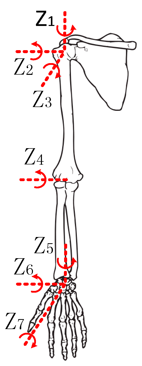
The structure of the human arm is complex, so the joints and segments of a human arm are usually simplified into a 7-DOF kinematic system [19], as shown in Figure 1. The shoulder joint can be modeled as a 3-DOF ball-and-socket joint: flexion/extension , abduction/adduction and internal/external-rotation ; The wrist joint can be modeled as a 3-DOF ball-and-socket joint: palmar flexion/dorsiflexion , ulnar deviation/radial deviation and medial rotation ; The elbow joint can be modeled as a 1-DOF hinge joint with [20,21,22]. The motion range of the joints is shown in Table 1 [23]. Here, the ball-and-socket wrist joint with 3-DOF is primarily used to ensure the flexibility of the end-effector. Because the exoskeleton mainly performs lifting, pulling and pushing of a load during material handling, it does not require the end-effector to have the same DOFs as the hand. To further simplify the structure, only the wrist internal/external-rotation is retained. The elbow joint is considered a 2-DOF joint, i.e., flexion/extension and pronation/supination [24].
Based on the above analysis, a hydrodynamic 5-DOF upper-limb exoskeleton was designed, as shown in Figure 2. The 5 DOFs are as follows: shoulder flexion/extension , shoulder adduction/abduction , shoulder internal/external-rotation , elbow flexion/extension and elbow pronation/supination . While operating the 5-DOF upper-limb exoskeleton, the operator can drive the exoskeleton through the handle, the exoskeleton upper-arm and forearm fit perfectly with the upper-arm and the forearm of the human body, and a strap between the human and exoskeleton is not required. We measured the motion range of the upper-limb of human body when performing the typical movements of material handling (raising up and lateral lifting), and after appropriately increasing and rounding to the value of the range, the motion range of the 5-DOF upper-limb exoskeleton was obtained. The motion range of the 5-DOF upper-limb exoskeleton is described in Table 2.
The 5-DOF upper-limb exoskeleton that has similar degrees of freedom to human body is a typical anthropomorphic upper-limb exoskeleton. The power-assisted principle of the 5-DOF upper-limb exoskeleton shoulder and elbow is the same as that of the XOS2 [2,3], the Body Extender system [4,5,6] and the HEXAR [1] when carrying loads. Thus, the workspace, the joint torque and the power consumption of the anthropomorphic upper-limb exoskeleton are obtained by analyzing the 5-DOF upper-limb exoskeleton.
2.2. Principle of the 3-DOF Upper-Limb Exoskeleton
The 5-DOF upper-limb exoskeleton has characteristics of flexibility due to the multiple degrees of freedom, but too many degrees of freedom will lead to a complex structure, which increases the self-weight. Therefore, the degrees of freedom of the 5-DOF upper-limb exoskeleton are analyzed and optimized. The function of the degrees of freedom of the 5-DOF upper-limb exoskeleton is shown in Table 3.
The shoulder flexion/extension , elbow flexion/extension and shoulder adduction/abduction are significant for performing tasks. The shoulder internal/external-rotation and elbow pronation/supination are mainly used to increase workspace and flexibility. The weights of these two joints and the corresponding actuators account for 24% of the total weight of the 5-DOF upper-limb exoskeleton. In order to simplify the structure and reduce weight, the shoulder internal/external-rotation , elbow pronation/supination and their actuators are removed, which will cause the problem of a smaller workspace. To solve this problem, internal-rotation of the elbow flexion/extension by around the upper-arm will create a new degree of freedom: elbow external-flexion/internal-extension (Elbow EF/IE) . The problem of flexibility in the end-effector is solved by the tools designed for different loads.
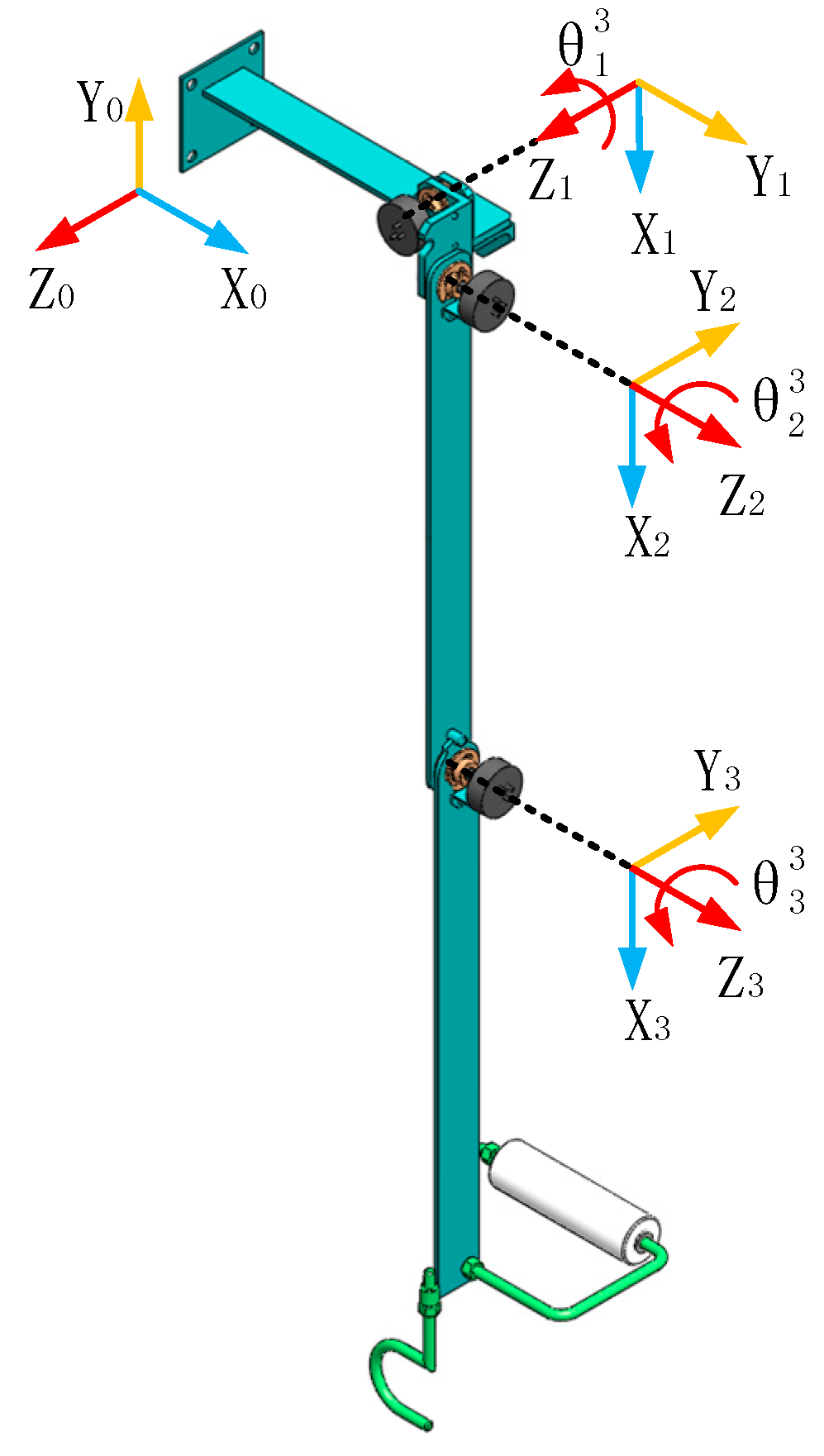
Based on the results of the above analysis, a non-anthropomorphic 3-DOF upper-limb exoskeleton with an internally rotated elbow joint is proposed. The 3 DOFs include the following: shoulder flexion/extension , shoulder adduction/abduction and elbow external-flexion/internal-extension , as shown in Figure 3. Different from the 5-DOF upper-limb exoskeleton, when the upper-limb of the human body performs elbow flexion/extension in the sagittal plane, the 3-DOF upper-limb exoskeleton performs elbow external-flexion/internal-extension in the plane of the vertical sagittal plane; the exoskeleton and the human arm are not fully attached together. According to the motion range of human joints and the motion range of the 5-DOF upper-limb exoskeleton, the motion range of the 3-DOF upper-limb exoskeleton is determined, as shown in Table 4.
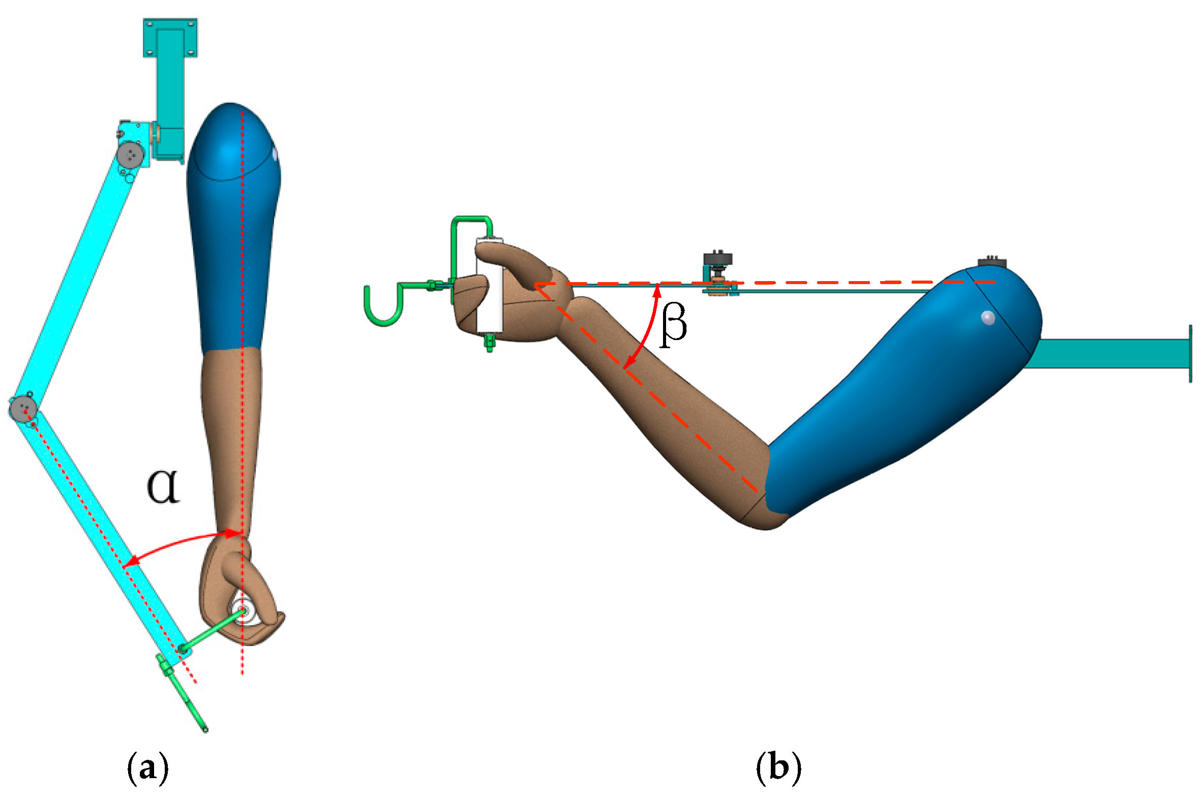
As described in Figure 2, the 5-DOF upper-limb exoskeleton is an anthropomorphic structure. The length of the upper-arm and the forearm can refer to the human body, but the 3-DOF upper-limb exoskeleton is a non-anthropomorphic structure. The length of the upper-arm and forearm is determined by the workspace of the 5-DOF upper-limb exoskeleton and the angle between the forearm of the exoskeleton and the sagittal plane, shown in Figure 4a, so that the 3-DOF upper-limb exoskeleton has the same workspace as the 5-DOF upper-limb exoskeleton.
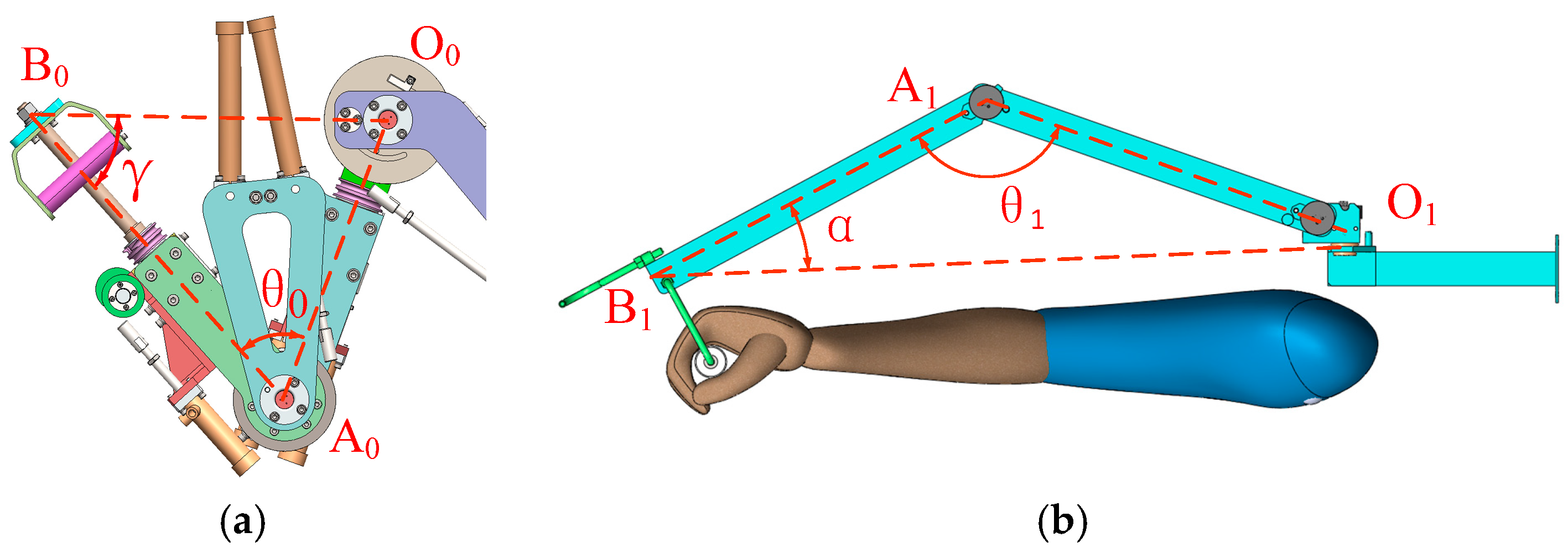
In order for the 3-DOF upper-limb exoskeleton to reach the workspace of the 5-DOF upper-limb exoskeleton, the distance between the end-effector and the shoulder should be the same as that of the 5-DOF upper-limb exoskeleton. The lengths of the upper-arm and forearm of the 5-DOF upper-limb exoskeleton are 330 mm and 370 mm, respectively. In the sagittal plane of the shoulder joint, the distance between the end-effector of the 5-DOF upper-limb exoskeleton and the shoulder joint is shown in Figure 5a. In the sagittal plane of the shoulder joint, the distance between the end-effector of the 3-DOF upper-limb exoskeleton and the shoulder joint is described in Figure 5b. . and represent the shoulder, and represent the elbow, and represent the end-effector, and represent the angle between the upper-arm and forearm, represents the angle between the upper-arm and the sagittal plane, and represent the upper-arm, and and represent the forearm.
In Figure 5a, and can be calculated as follows:
As shown in Table 2, , and using Equations (1) and (2), the result is derived, where is and and have the same range of variation of .
In Figure 5b, and can be calculated as follows:
As shown in Table 3, , , and using Equations (3) and (4), the result is derived, where is , is , and is .
2.3. Differences Analysis
Since the elbow joint of the 3-DOF upper-limb exoskeleton is internally rotated , the upper-arm and forearm of the exoskeleton are not parallel to the human arm. This problem mainly occurs when the human elbow performs the flexion action, i.e., elbow is in a non-straight state.
In the course of work, the impact of non-parallel is mainly reflected in two aspects:
- There is an angle between the forearm of the exoskeleton and the sagittal plane, as shown in Figure 4a. This results in the relative rotation between the end-effector and the hand. When the flexion of the elbow joint of the human body is at a maximum, the angle of the relative rotation between the end-effector and the hand is . Since the movements of the end-effector under the control of the human are continuous and smooth, angle does not affect the manipulability of the exoskeleton. This will be verified by the experiment in Section 5.
- The length of the human upper arm and forearm refer to human dimensions of Chinese adults, which is the National Standard of the People’s Republic of China, as shown in Figure 4b. There is an angle between the human forearm and the plane formed by the upper-arm and forearm of the exoskeleton. This results in ulnar deviation in the human wrist. When the elbow flexion of human body is at a maximum, the ulnar deviation is . The maximum ulnar deviation allowed by the physiological structure is [23], which is greater than angle . Therefore, ulnar deviation does not affect the manipulation of the exoskeleton.
2.4. Singularity Analysis
Since the mechanical system will lose some degrees of freedom at the singular points, some motions cannot be achieved. So, singularities should be avoided in the design [20].
As described in Figure 2, the 5-DOF upper-limb exoskeleton is in the singular position. With this configuration, the arm is obliquely upward, i.e., . In this position, abduction or adduction motion cannot be achieved, because the rotation axes of and are collinear.
Since the 3-DOF upper-limb exoskeleton does not have two or more collinear rotation axes inside the workspace, there is no singularity within the workspace [25], and it is not necessary to avoid singularity in the workspace by rotating the axis of the coordinate or using redundant degrees of freedom [4,20].
3. Kinematic Analysis
In order to verify whether the end-effector of the 3-DOF upper-limb exoskeleton can reach all points within the workspace of the 5-DOF upper-limb exoskeleton, the 5-DOF upper-limb exoskeleton and the 3-DOF upper-limb exoskeleton are analyzed with forward and inverse kinematics methods, respectively.
3.1. Forward Kinematics Analysis of the 5-DOF Upper-Limb Exoskeleton
Elbow pronation/supination has no effect on the size of the workspace, so it is considered a fixed constraint in the kinematics modeling. In order to simplify the configuration, the tilt of the abduction/adduction axis of the shoulder joint is removed, and the flexion/extension range of the shoulder joint is changed accordingly. Then, the kinematic model is obtained, as shown in Figure 6. The kinematics of the 5-DOF upper-limb exoskeleton is analyzed with the Denavit-Hartenberg parameters (DH), where 0 is the initial coordinate. The DH parameters are listed in Table 5.
3.2. Inverse Kinematics Analysis of the 3-DOF Upper-Limb Exoskeleton
Given an arbitrary end-effector position of the 5-DOF upper-limb exoskeleton in the workspace, the corresponding joint angles of the 3-DOF upper-limb exoskeleton can be calculated using inverse kinematics. In case the obtained angles are in the motion range of the corresponding joint, the 3-DOF upper-limb exoskeleton can reach the position of the 5-DOF upper-limb exoskeleton in the workspace, i.e., the given position is in the workspace of the 3-DOF upper-limb exoskeleton.
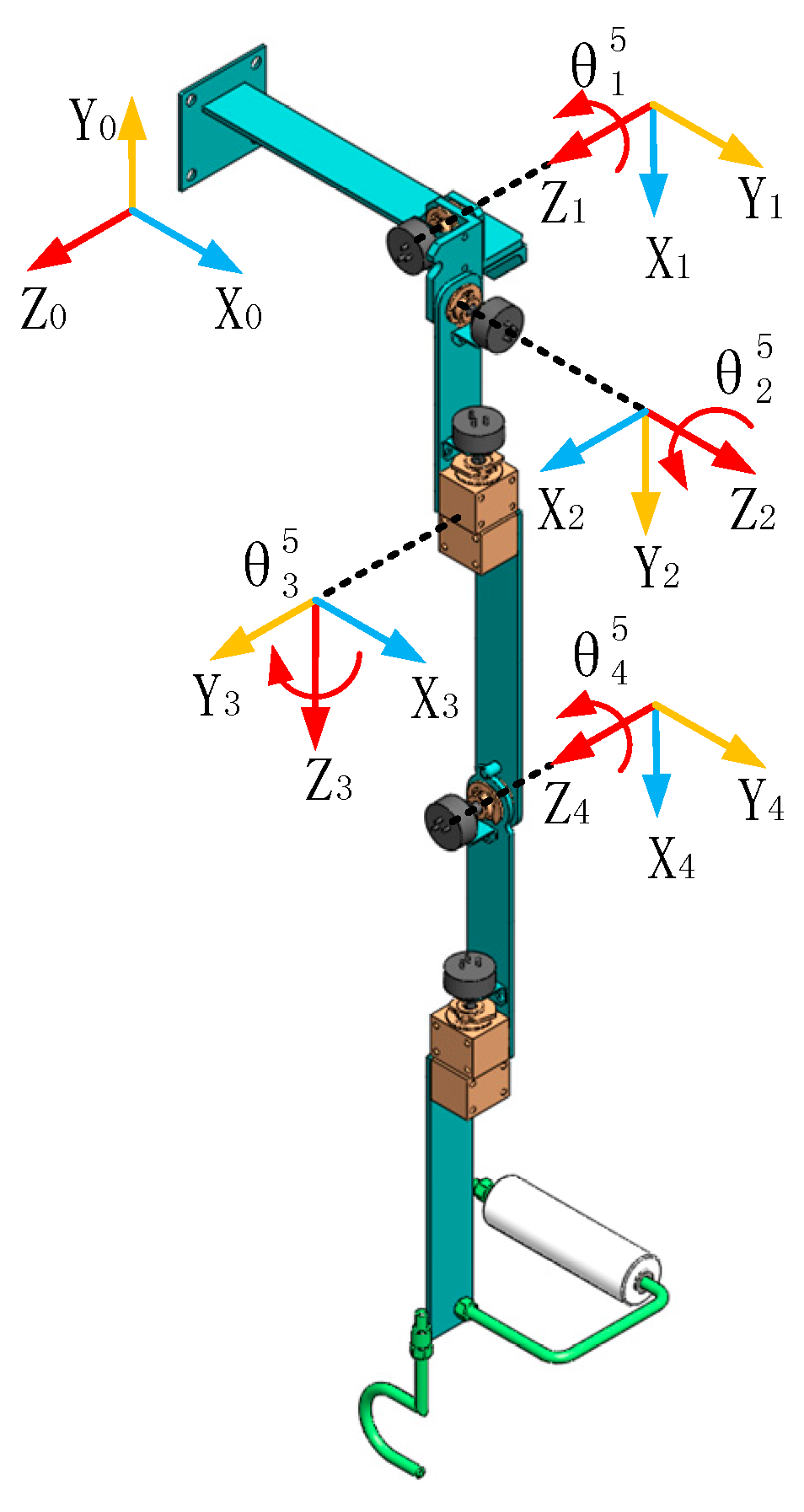
According to the previous results, the kinematics of the 3-DOF upper-limb exoskeleton are analyzed with the Denavit-Hartenberg parameters (DH), where 0 is the initial coordinate, as shown in Figure 3. The DH parameters are listed in Table 6.
The extrema of , and obtained by inverse kinematics are listed in Table 7 [26]. The range of listed extremum shown in Table 7 is greater than the range of elbow external-flexion/internal-extension shown in Table 4. The motion range of the elbow joint actuator in the 5-DOF upper-limb exoskeleton reaches . It is feasible to reference this parameter as the motion range of the elbow external-flexion/internal-extension , thus derived from inverse kinematics meets the motion range of the 3-DOF upper-limb exoskeleton.
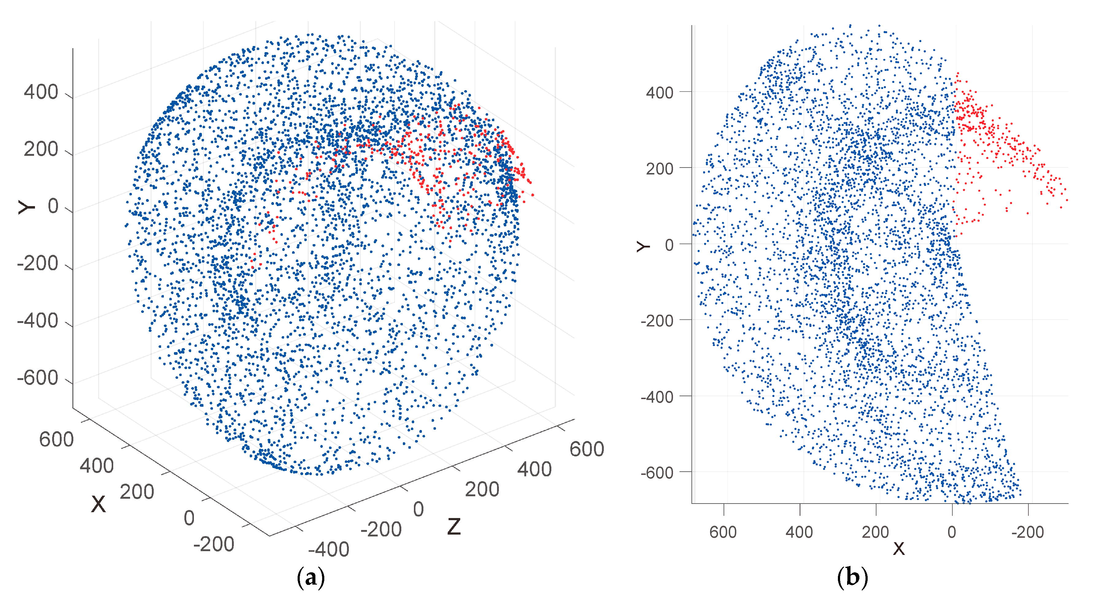
Based on the motion range of the 3-DOF upper-limb exoskeleton in Table 4, the workspace of the 5-DOF upper-limb is divided into two parts: Part of the workspace that the 3-DOF upper-limb exoskeleton can reach called valid workspace; and part of the workspace that the 3-DOF upper-limb exoskeleton cannot reach called invalid workspace. The inverse kinematics workspace consists of valid workspace and invalid workspace (Figure 8). The area consisting of the blue points is the valid workspace, and the area consisting of the red points is the invalid workspace. Here, the x-axis is in the same direction as the exoskeleton, and point (0,0,0) is the center of shoulder flexion/extension.
A total of 5001 points are placed in the inverse kinematics workspace, with 4621 points placed in the valid workspace, accounting for approximately 92.4%, and 380 points placed in the invalid workspace, accounting for approximately 7.6%. The invalid workspace is located behind the coronal plane of the shoulder joint. The end-effector of the 5-DOF upper-limb exoskeleton will not reach this area, while the valid workspace is the actual workspace of the 5-DOF upper-limb exoskeleton when working. The existence of invalid workspace does not affect the accessibility of the 3-DOF upper-limb exoskeleton, i.e., the 3-DOF upper-limb exoskeleton can reach all points in the actual workspace of the 5-DOF upper-limb exoskeleton.
4. Dynamics Analysis
The upper-limb exoskeleton used for material handing is mainly used to perform lifting, pulling, pushing, raising and other complex movements in front of the body, or lifting on the side of the body. To obtain the loading conditions on the joints of the two exoskeletons during work, they are analyzed by dynamics through two typical movements: raising up and lateral lifting.
4.1. Joint Trajectories
Figure 9 shows the given end-effector trajectory, based on the structure and parameters of the 5-DOF upper-limb exoskeleton. The end-effector trajectory of raising-up is located in the sagittal plane of the shoulder joint; the end-effector trajectory of lateral-lifting is located in the coronal plane of the shoulder joint while the elbow joint is straight. The parameters of the two movements are shown in Table 8. describes the shoulder joint; , describe the initial position of the elbow and the end-effector; , describe the end position of the elbow and the end-effector; and , describe the projection on the ground of the end-effectors.
4.2. Dynamics
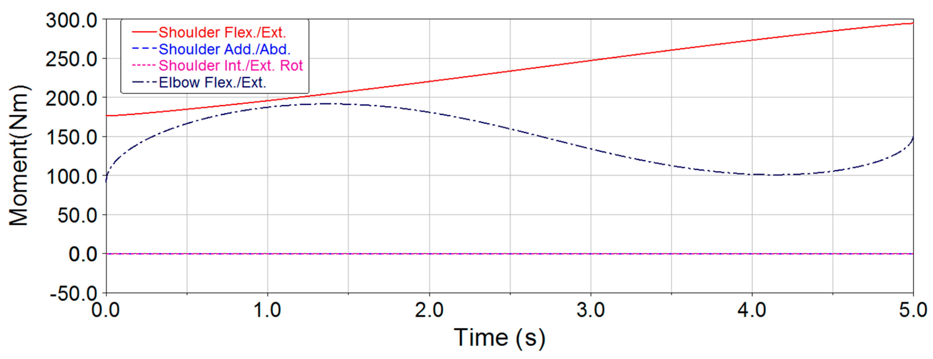
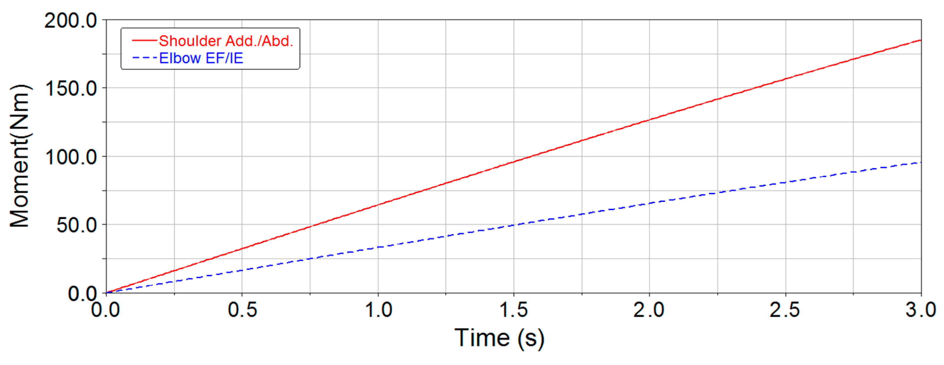
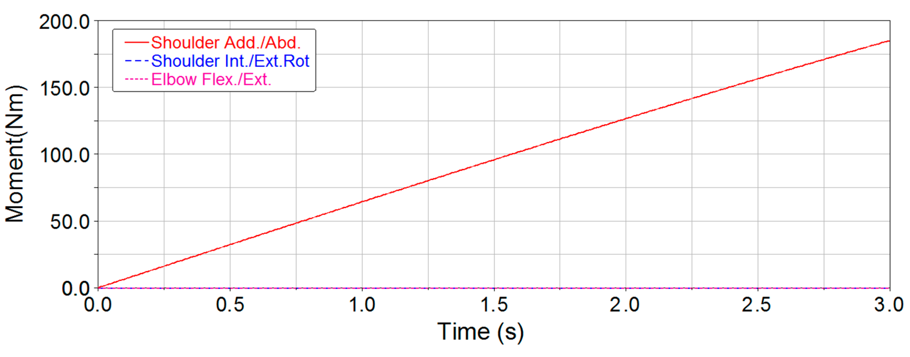
The upper-arm and the forearm of the 5-DOF upper-limb exoskeleton are 330 mm and 370 mm, and the upper-arm and the forearm of the 3-DOF upper-limb exoskeleton are 328 mm and 372 mm, respectively. The load capacity of the upper-limb exoskeleton for material hanging is heavy, and the design index of the 5-DOF upper-limb exoskeleton lifting capacity is 50 kg. In order to compare the characteristics of the two exoskeletons with a heavy load, the load on both end-effectors is 50 kg. The load on the end-effector is much heavier than the upper arm and the forearm of the 5-DOF upper-limb exoskeleton; therefore, the exoskeleton is considered as a 0 mass in the dynamic analysis. The time for raising up and lateral lifting is 5 s and 3 s, respectively, which refers to the rounded time of the human body to perform the actual actions. The dynamic equations of motion for the two exoskeletons are derived using the Lagrange method, and joint torques can be solved [27]. Figure 10, Figure 11, Figure 12 and Figure 13 show the joint torque curves. Because shoulder flexion/extension (,) of the two exoskeletons does not work during lateral-lifting, the joint torques and power consumption of the two joints will not be considered in the process.
Since elbow torque is mainly borne by structural components during raising up, the maximum elbow joint torque of the 3-DOF upper-limb exoskeleton is significantly reduced. According to the simulation results, the maximum joint torques in the two exoskeletons are obtained during the process of raising up and lateral lifting (Table 9).
From Table 9, the maximum joint torques of shoulder flexion/extension and shoulder adduction/abduction for the two exoskeletons are identical during the process of raising up and lateral lifting, but compared with elbow flexion/extension of the 5-DOF upper-limb exoskeleton, the maximum joint torque of elbow external-flexion/internal-extension for the 3-DOF upper-limb exoskeleton was reduced by approximately 50%.
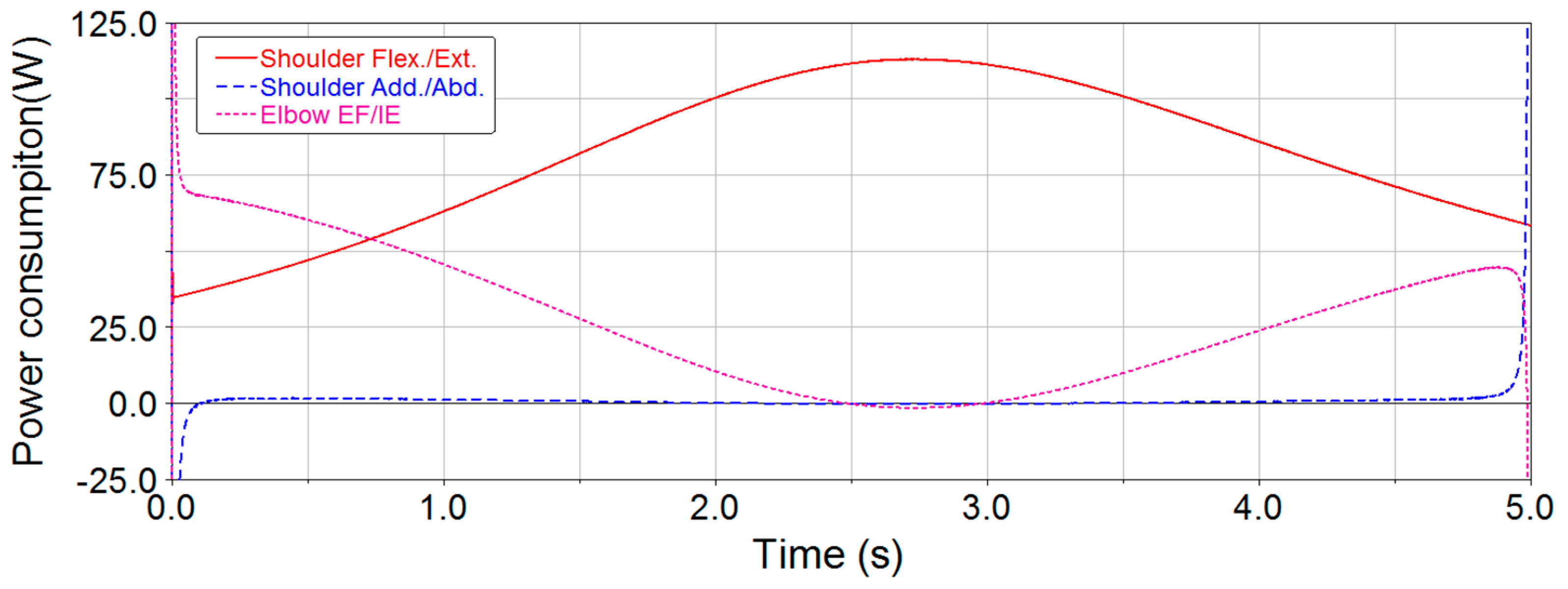
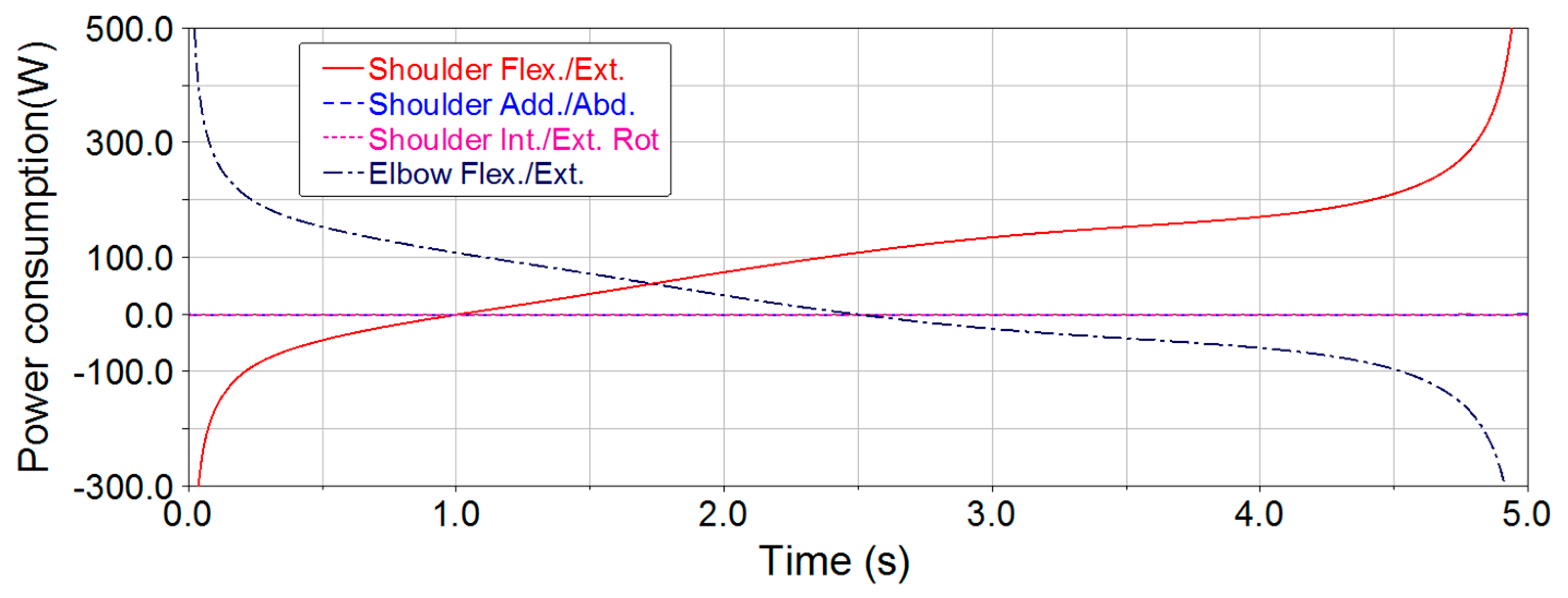
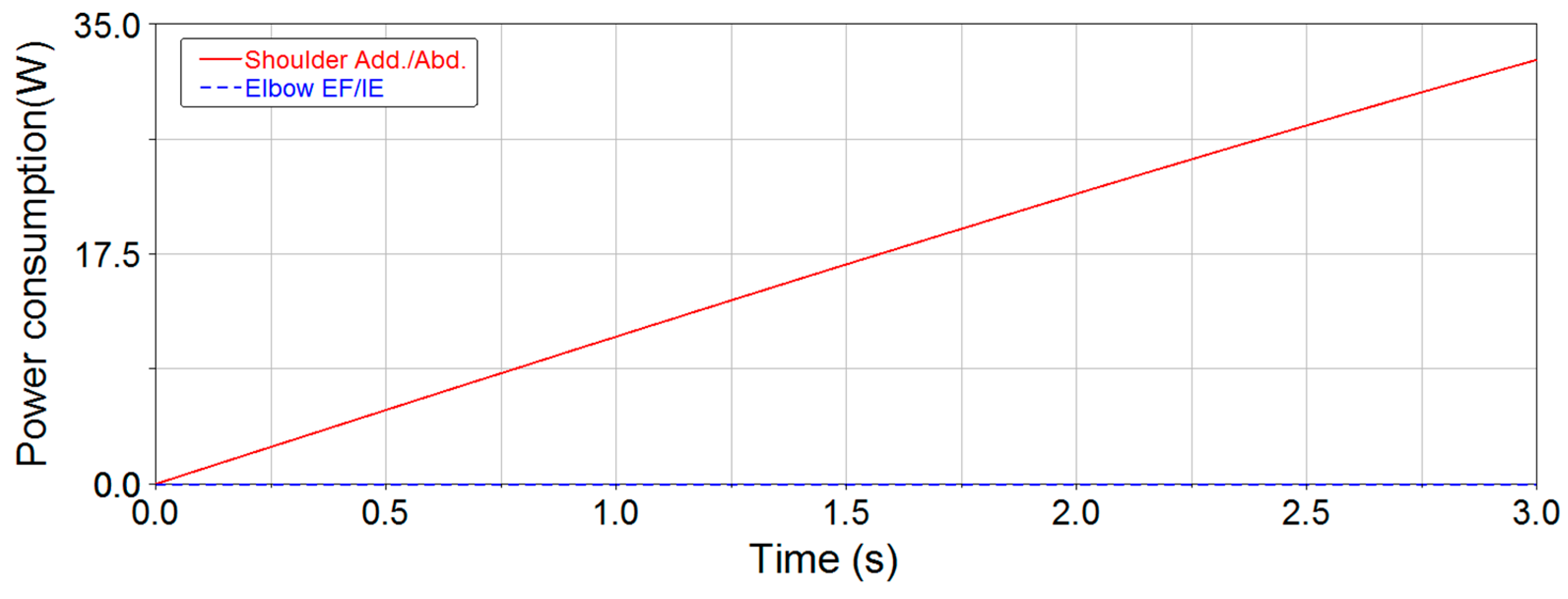
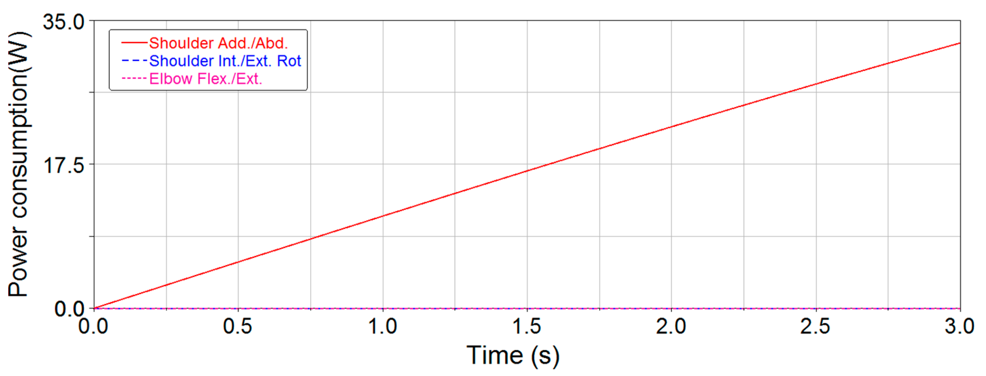
According to the joint torque curves and angular velocity obtained by kinematics, the joint power consumption curves can be further obtained (Figure 14, Figure 15, Figure 16 and Figure 17).
From Figure 14 and Figure 15, the joint power consumption for the 3-DOF upper-limb exoskeleton is smoother than for the 5-DOF upper-limb exoskeleton during raising up. During the course of raising up, the end-effector attempts to have uniform motion along the trajectory, so there are significant mutations in the power consumption curves of the two exoskeletons at the beginning and at the end. The maximum power consumption time for each joint is selected in the smooth section to avoid the mutation, i.e., set t = 0.1 s for the maximum elbow external-flexion/internal-extension power consumption time in Figure 14, and set t = 0.5 s and t = 4.5 s for the maximum elbow flexion/extension and shoulder flexion/extension power consumption time in Figure 15. The maximum joint power consumption is shown in Table 10.
From Table 10, the maximum joint power consumption of shoulder flexion/extension and elbow external-flexion/internal-extension for the 3-DOF upper-limb exoskeleton is reduced by 46% and 55%, respectively, compared to the 5-DOF upper-limb exoskeleton.
In conclusion, compared with the 5-DOF upper-limb exoskeleton, the maximum elbow joint torque of the 3-DOF upper-limb exoskeleton is significantly reduced, the power consumption curves are smoother, maximum joint power consumptions of the shoulder and elbow decrease significantly, and the mechanism is more feasible. Since the design and selection of the joint actuators are based on the maximum joint torque and power consumption, the volume and weight of the shoulder joint and elbow joint of the 3-DOF upper-limb exoskeleton will be further reduced.
5. Experiment
5.1. Posture Analysis
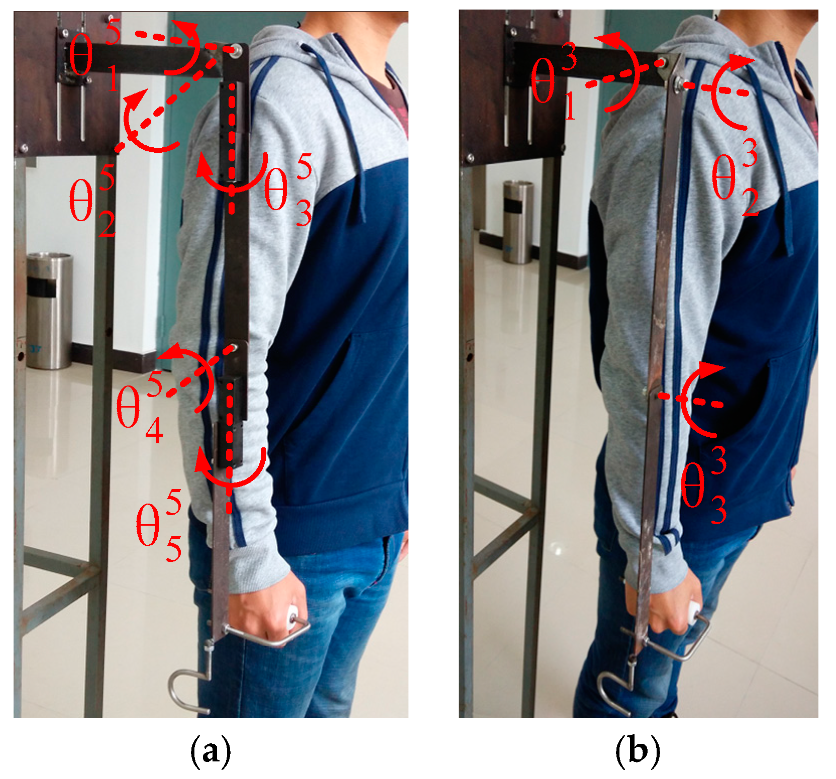
The unactuated 5-DOF upper-limb exoskeleton and the 3-DOF upper-limb exoskeleton were manufactured as exoskeleton prototypes, as shown in Figure 18.
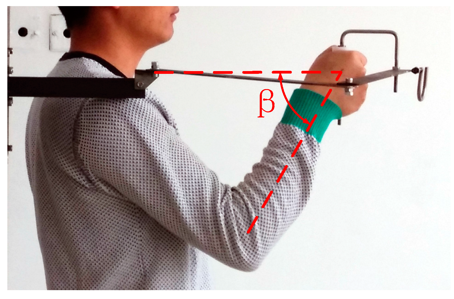
When the handle is closest to the shoulder joint, maximum ulnar deviation of the wrist occurs. In the experiment, the user could drive the exoskeleton smoothly to this position, i.e., the ulnar deviation of the wrist does not affect operation, as shown in Figure 19.
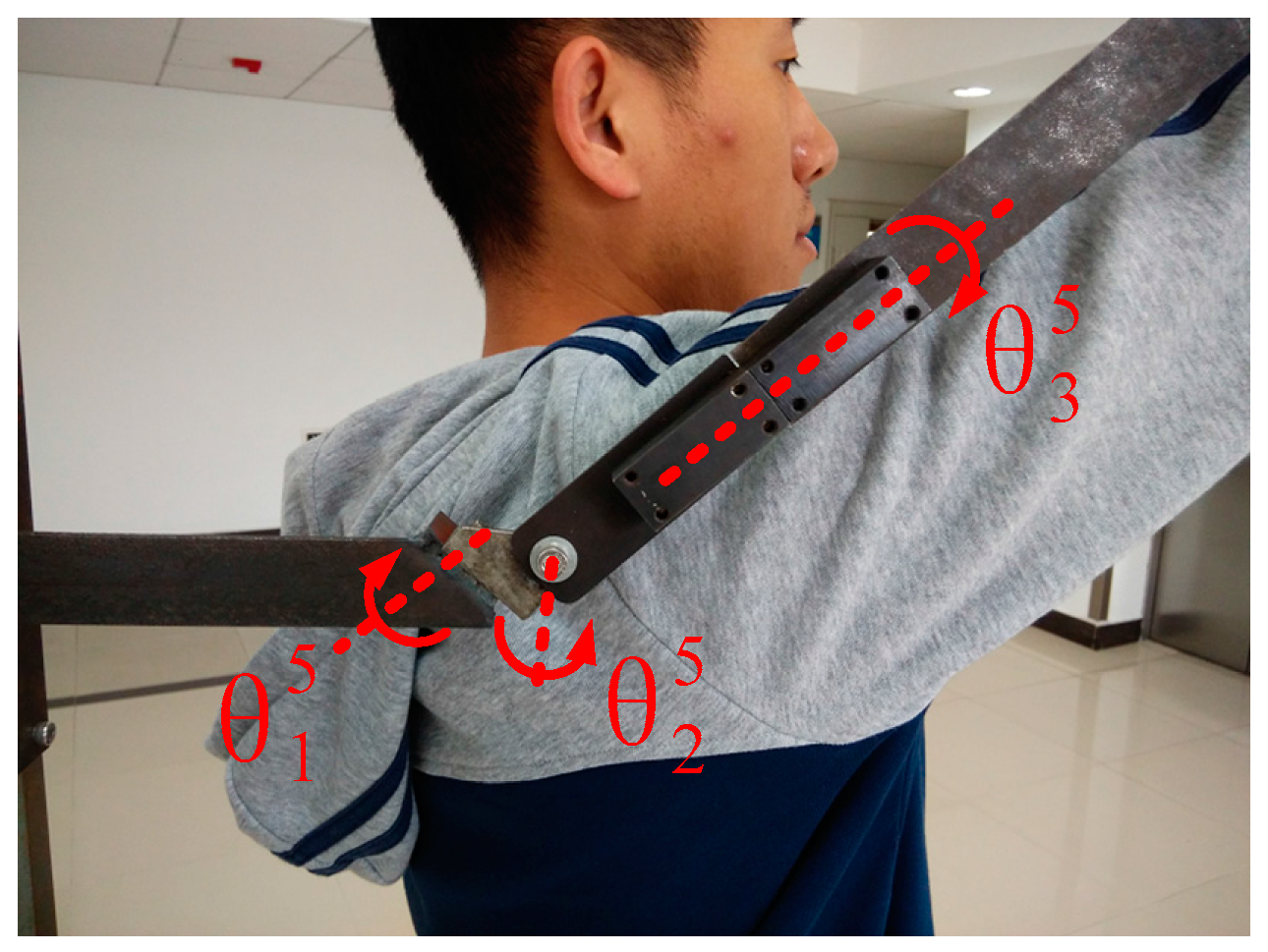
As described in Figure 20, the 5-DOF exoskeleton prototype was obliquely upward. In this position, the rotation axes of shoulder adduction/abduction and shoulder internal/external-rotation were collinear; thus, it was the singularity position in the workspace of the 5-DOF exoskeleton prototype.
5.2. Motion Analysis
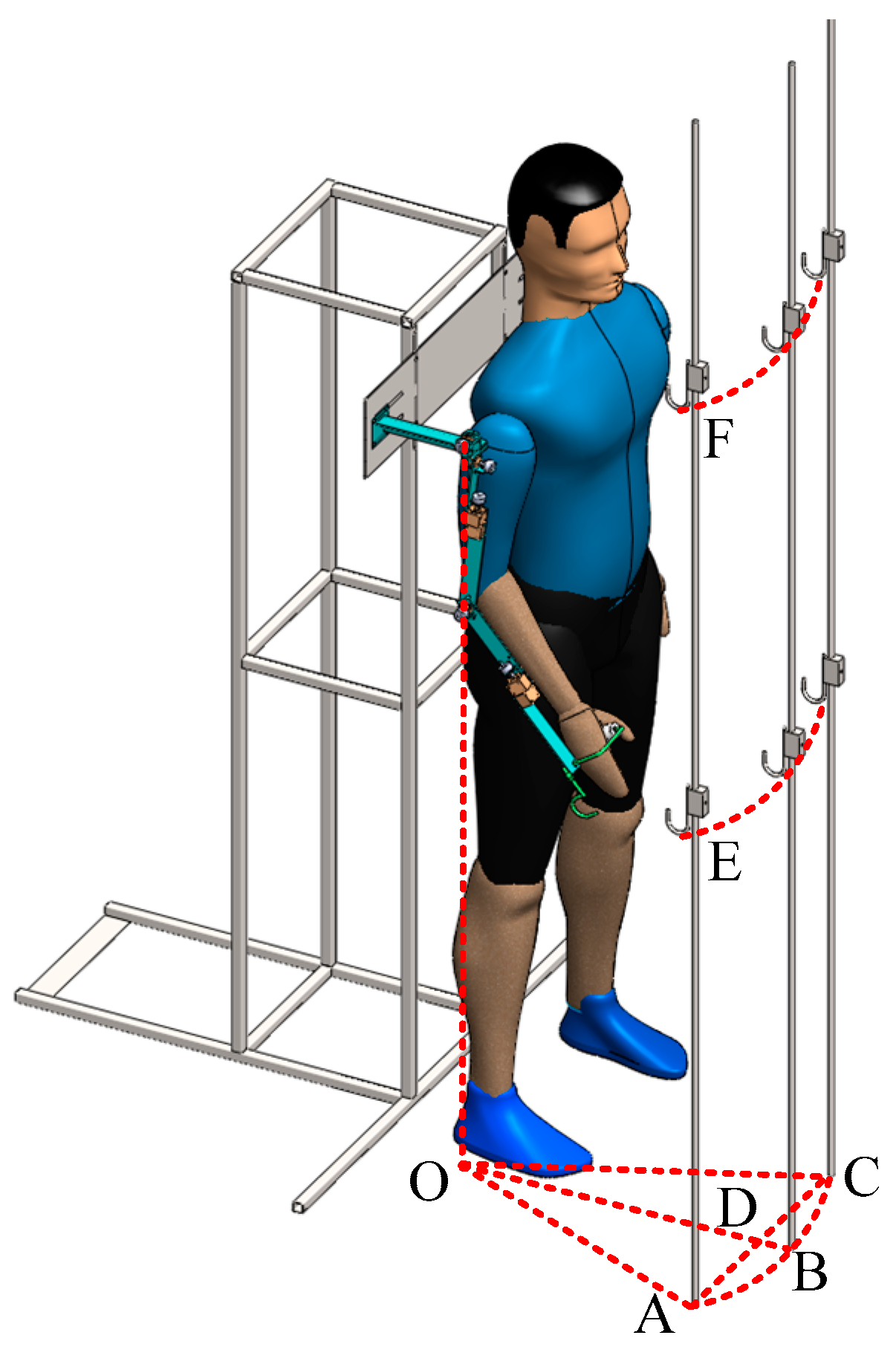
The manipulability of the exoskeleton prototype could be verified by the effect and time of the hanging action. In the experiment, as shown in Figure 21, three vertical rods were placed in front of the shoulder joint (), in left-front of the shoulder joint (, ) and in right-front of the shoulder joint (, ), and two hooks (, ) were placed on each of the rods.
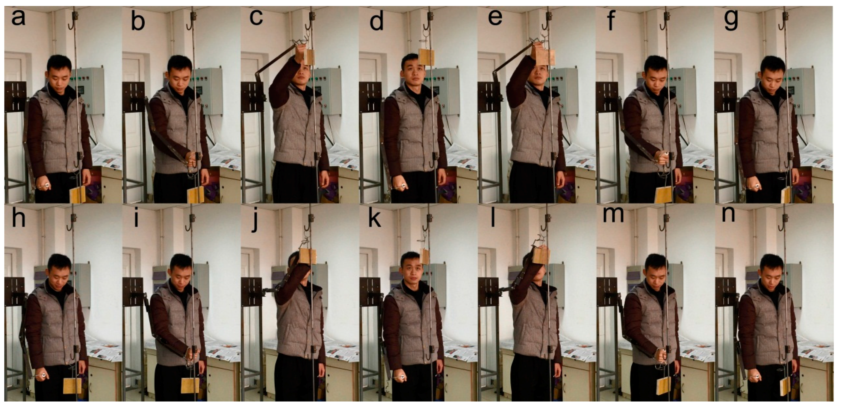
Six healthy subjects (all males, height: ) participated in the experiment. The participants wore two different exoskeleton prototypes: the 3-DOF exoskeleton prototype and the 5-DOF exoskeleton prototype. They were asked to perform two actions in one test while holding the handle, as shown in Figure 22. A complete hanging action should include the following procedure:
- Starting from the body side, remove the load from the lower hook, hang the load on the upper hook, and replace the exoskeleton prototype back to the body side.
- Starting from the body side, remove the load from the upper hook, hang the load on the lower hook, and replace the exoskeleton prototype back to the body side.
To ensure the accuracy of the experiment, the participants were required to make the action as smooth as possible under the premise of ensuring comfort and action. Each of the participants wore two exoskeleton prototypes and completed the action 10 times in front of the shoulder, left-forward of the shoulder and right-forward of the shoulder. The experimental process was recorded using a camera. The action completion time was compared using a t-test [20].
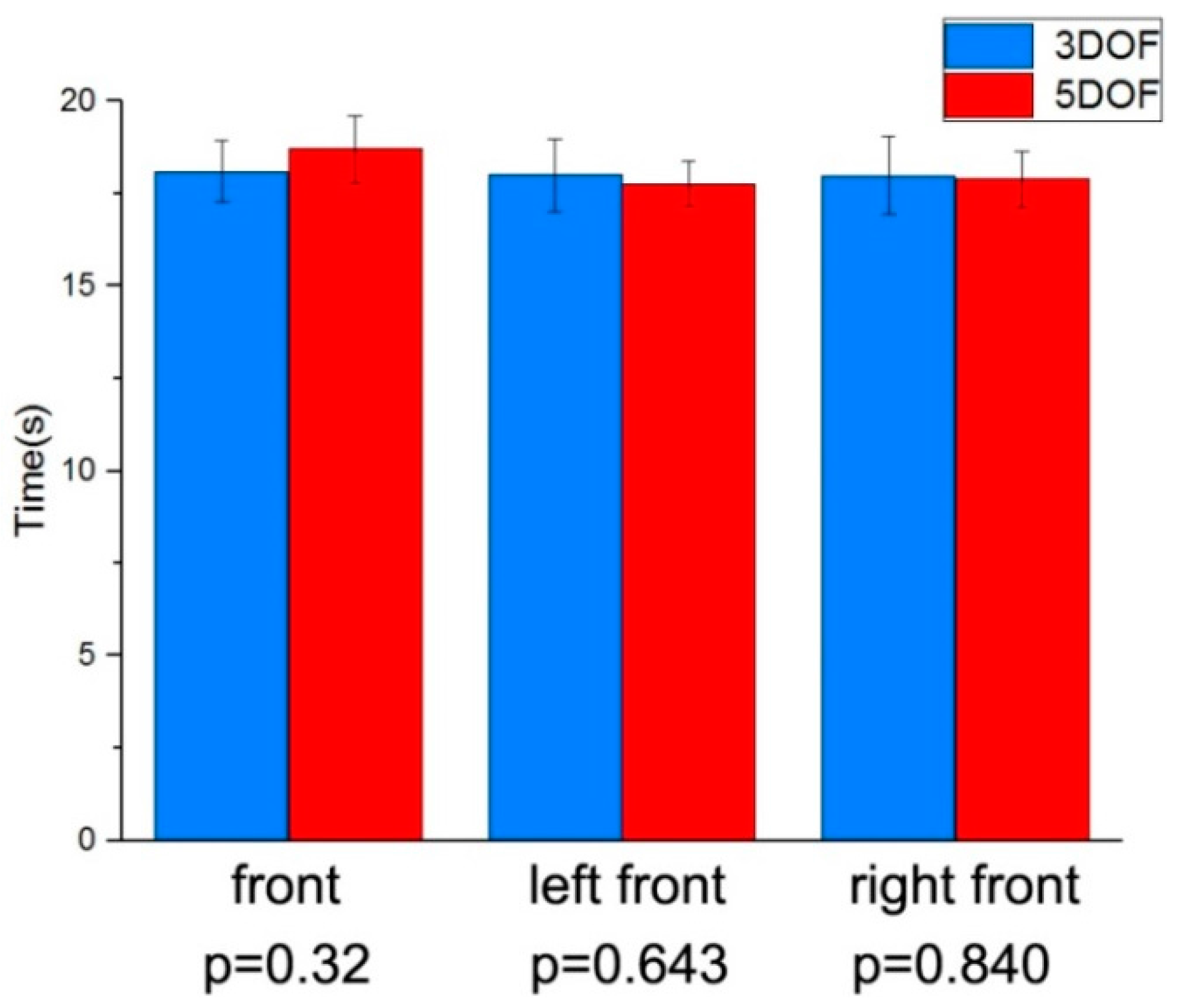
The statistical analysis results of the two exoskeleton prototypes are shown in Figure 23. The thick bars and thin lines represent the mean values and standard deviations of the data, respectively. The p-values of the t-test are located at the bottom of the graph. The maximum average time for completing the 10 actions using the 3-DOF exoskeleton prototype was 18.1 s, and it was 18.7 s using the 5-DOF exoskeleton prototype. The angle between the exoskeleton forearm and the sagittal plane does not affect the manipulability of the exoskeleton. Also, the p-values are quite high; there is no statistical difference in the time for the two exoskeletons to complete the action [20]. This shows that, compared with the 5-DOF exoskeleton prototype, the 3-DOF exoskeleton prototype has the same manipulability, and it also further verified that the ulnar deviation did not affect the manipulability.
6. Conclusions
A non-anthropomorphic 3-DOF upper-limb exoskeleton with an internally rotated elbow joint for material handling was proposed and analyzed based on the typical anthropomorphic 5-DOF upper-limb exoskeleton for power-assisted activity in this paper. The conclusions are as follows:
- The proposed 3-DOF exoskeleton had a reduced self-weight by removing two joints, and their corresponding actuators and eliminated singularity in the workspace. In addition, it is not necessary to avoid singularity in the workspace by means of rotating the base coordinate axis or the design of redundant degrees of freedom.
- The kinematics and dynamics analysis showed that the 3-DOF upper-limb exoskeleton had the same actual workspace as the 5-DOF upper-limb exoskeleton; compared with the 5-DOF upper-limb exoskeleton, the maximum joint torque of the 3-DOF upper-limb exoskeleton decreased by 50%, and the elbow external-flexion/internal-extension and the shoulder flexion/extension power consumption decreased by 55% and 46%, respectively, which will further reduce the exoskeleton weight.
- The experimental results showed that the angle between the forearm of the 3-DOF upper-limb exoskeleton and the sagittal plane and the ulnar deviation had no influence on operating tasks; therefore, the proposed 3-DOF upper-limb exoskeleton with an internally rotated elbow joint had the same manipulability as the 5-DOF upper-limb exoskeleton for the hanging action process.
The concept of a non-anthropomorphic 3-DOF upper-limb exoskeleton with an internally rotated elbow joint was verified using simulations and experiments in this paper. For future work, a non-anthropomorphic 3-DOF upper-limb exoskeleton with actuators and sensors will be designed and manufactured; the exoskeleton control will also be studied and discussed.
Acknowledgments
This work is supported by the National Key R&D Program of China “The study on Load-bearing and Moving Support Exoskeleton Robot Key Technology and Typical Application” under Grant No. 2017YFB1300500. We would like to thank the editor and all anonymous reviewers for their constructive suggestions.
Author Contributions
All authors made significant contributions to this article. Xin Wang was responsible for developing the exoskeletons, performing the experiments, and writing the paper, Qiuzhi Song, the corresponding author, was mainly responsible for the revision of the paper, Xiaoguang Wang was responsible for dynamics simulation, conceiving and designing the experiments, and Pengzhan Liu was responsible for performing the experiments and processing the experimental data.
Conflicts of Interest
The authors declare no conflict of interest.
References
- Lee, H.D.; Lee, B.K.; Kim, W.S.; Han, J.S.; Shin, K.S.; Han, C.S. Human-robot cooperation control based on a dynamic model of an upper limb exoskeleton for human power amplification. Mechatronics 2014, 24, 168–176. [Google Scholar] [CrossRef]
- Karlin, S. Raiding Iron Man’s Closet. IEEE Spectr. 2011, 48, 25. [Google Scholar] [CrossRef]
- Bogue, R. Exoskeletons and robotic prosthetics: A review of recent developments. Ind. Robot 2009, 36, 421–427. [Google Scholar] [CrossRef]
- Bergamasco, M.; Salsedo, F.; Marcheschi, S.; Lucchesi, N. A Novel Actuator for Wearable Robots with Improved Torque Density and Mechanical Efficiency. Adv. Robot. 2010, 24, 2019–2041. [Google Scholar] [CrossRef]
- Bergamasco, M.; Salsedo, F.; Marcheschi, S.; Lucchesi, N.; Fontana, M. A Novel Compact and Lightweight Actuator for Wearable Robots. In Proceedings of the 2010 IEEE International Conference on Robotics and Automation, Anchorage, AK, USA, 3–8 May 2010; pp. 4197–4203. [Google Scholar]
- Marcheschi, S.; Salsedo, F.; Fontana, M.; Bergamasco, M. Body Extender: Whole Body Exoskeleton for Human Power Augmentation. In Proceedings of the 2011 IEEE International Conference on Robotics and Automation, Shanghai, China, 9–13 May 2011; pp. 611–616. [Google Scholar]
- Hayashi, T.; Kawamoto, H.; Sankai, Y. Control Method of Robot Suit HAL Working as Operator’s Muscle Using Biological and Dynamical Information. In Proceedings of the 2005 IEEE/RSJ International Conference on Intelligent Robots and Systems, Edmonton, AB, Canada, 2–6 August 2005; pp. 3455–3460. [Google Scholar]
- Kasaoka, K.; Sankai, Y. Predictive Control Estimating Operator’s Intention for Stepping-Up motion by Exo-Skeleton Type Power Assist System HAL. In Proceedings of the 2001 IEEE/RSJ International Conference on Intelligent Robots and Systems, Maui, HI, USA, 29 October–3 November 2001; pp. 1578–1583. [Google Scholar]
- Ivanova, G.; Bulavintsev, S.; Ryu, J.H.; Poduraev, J. Development of an Exoskeleton System for Elderly and Disabled People. In Proceedings of the 2011 International Conference on Information Science and Applications, Jeju Island, Korea, 26–29 April 2011. [Google Scholar]
- Yu, W.; Rosen, J. A Novel Linear PID Controller for an Upper Limb Exoskeleton. In Proceedings of the 2010 49th IEEE Conference on Decision and Control, Atlanta, GA, USA, 15–17 December 2010; pp. 3548–3553. [Google Scholar]
- Miller, L.M.; Rosen, J. Comparison of Multi-Sensor Admittance Control in Joint Space and Task Space for a Seven Degree of Freedom Upper Limb Exoskeleton. In Proceedings of the 2010 3rd IEEE RAS and EMBS International Conference on Biomedical Robotics and Biomechatronics, Tokyo, Japan, 26–29 September 2010; pp. 70–75. [Google Scholar]
- Perry, J.C.; Rosen, J. Design of a 7 Degree-of-Freedom Upper-Limb Powered Exoskeleton. In Proceedings of the First IEEE/RAS-EMBS International Conference on Biomedical Robotics and Biomechatronics, Pisa, Italy, 20–22 February 2006; pp. 805–810. [Google Scholar]
- Yoshimitsu, T.; Yamamoto, K. Development of a Power Assist Suit for Nursing Work. In Proceedings of the SICE 2004 Annual Conference, Sapporo, Japan, 4–6 August 2004; pp. 577–580. [Google Scholar]
- Yamamoto, K.; Ishii, M.; Noborisaka, H.; Hyodo, K. Stand Alone Wearable Power Assisting Suit—Sensing and Control Systems. In Proceedings of the RO-MAN 2004 13th IEEE International Workshop on Robot and Human Interactive Communication, Kurashiki, Japan, 20–22 September 2004; pp. 661–666. [Google Scholar]
- Kiguchi, K.; Rahman, M.H.; Sasaki, M.; Teramoto, K. Development of a 3DOF mobile exoskeleton robot for human upper-limb motion assist. Robot. Auton. Syst. 2008, 56, 678–691. [Google Scholar] [CrossRef]
- Martinez, F.; Retolaza, I.; Pujana-Arrese, A.; Cenitagoya, A.; Basurko, J.; Landaluze, J. Design of a Five Actuated DOF Upper Limb Exoskeleton Oriented to Workplace Help. In Proceedings of the 2nd Biennial IEEE/RAS-EMBS International Conference on Biomedical Robotics and Biomechatronics, Scottsdale, AZ, USA, 19–22 October 2008; pp. 169–174. [Google Scholar]
- Chen, W.; Xiong, C.; Sun, R.; Huang, X. A 10-Degree of Freedom Exoskeleton Rehabilitation Robot with Ergonomic Shoulder Actuation Mechanism. Int. J. Humanoid Robot. 2011, 8, 47–71. [Google Scholar] [CrossRef]
- Xiao, F.Y.; Gao, Y.S.; Wang, Y.; Zhu, Y.H.; Zhao, J. Design of a wearable cable-driven upper limb exoskeleton based on epicyclic gear trains structure. Technol. Health Care 2017, 25, S3–S11. [Google Scholar] [CrossRef] [PubMed]
- Garrido, J.; Yu, W.; Li, X.O. Modular design and control of an upper limb exoskeleton. J. Mech. Sci. Technol. 2016, 30, 2265–2271. [Google Scholar] [CrossRef]
- Jung, Y.; Bae, J. Kinematic Analysis of a 5-DOF Upper-Limb Exoskeleton with a Tilted and Vertically Translating Shoulder Joint. IEEE/ASME Trans. Mechatron. 2015, 20, 1428–1439. [Google Scholar] [CrossRef]
- Wu, T.M.; Wang, S.Y.; Chen, D.Z. Design of an exoskeleton for strengthening the upper limb muscle for overextension injury prevention. Mech. Mach. Theory 2011, 46, 1825–1839. [Google Scholar] [CrossRef]
- Wu, Q.C.; Wang, X.S.; Du, F.P. Development and analysis of a gravity-balanced exoskeleton for active rehabilitation training of upper limb. Proc. Inst. Mech. Eng. C J. Mech. Eng. Sci. 2016, 230, 3777–3790. [Google Scholar] [CrossRef]
- Huang, X.; Yan, T. Rehabilitation Medicine, 5th ed.; People’s Medical Publishing House (PMPH): Beijing, China, 2013; pp. 45–48. ISBN 9787117172646. [Google Scholar]
- Chen, W.B.; Xiong, C.H.; Huang, X.L.; Sun, R.L.; Xiong, Y.L. Kinematic analysis and dexterity evaluation of upper extremity in activities of daily living. Gait Posture 2010, 32, 475–481. [Google Scholar] [CrossRef] [PubMed]
- Craig, J.J. Introduction to Robotics Mechanics and Control, 3rd ed.; China Machine Press: Beijing, China, 2006; pp. 119–120. ISBN 7111186818. [Google Scholar]
- Paul, R.P.; Shimano, B.; Mayer, G.E. Kinematic Control Equations for Simple Manipulators. IEEE Trans. Syst. Man Cybern. 1981, 11, 449–456. [Google Scholar]
- Mao, Y.; Agrawal, S.K. Design of a Cable-Driven Arm Exoskeleton (CAREX) for Neural Rehabilitation. IEEE Trans. Robot. 2012, 28, 922–931. [Google Scholar] [CrossRef]
Figure 1.
Kinematic model of the upper-limb of the human body.

Figure 2.
(a) The model of the 5-DOF upper-limb exoskeleton; and (b) The 5-DOF upper-limb exoskeleton.
Figure 2.
(a) The model of the 5-DOF upper-limb exoskeleton; and (b) The 5-DOF upper-limb exoskeleton.

Figure 3.
Kinematic configuration and coordinates of the 3-DOF upper-limb exoskeleton.

Figure 4.
Working configuration of the 3-DOF upper-limb exoskeleton. (a) Top view; and (b) right view.
Figure 4.
Working configuration of the 3-DOF upper-limb exoskeleton. (a) Top view; and (b) right view.

Figure 5.
Distance between the end-effector and shoulder joint: (a) 5-DOF upper-limb exoskeleton; and (b) 3-DOF upper-limb exoskeleton.
Figure 5.
Distance between the end-effector and shoulder joint: (a) 5-DOF upper-limb exoskeleton; and (b) 3-DOF upper-limb exoskeleton.

Figure 6.
Kinematic configuration and coordinate of the 5-DOF upper-limb exoskeleton.

Figure 7.
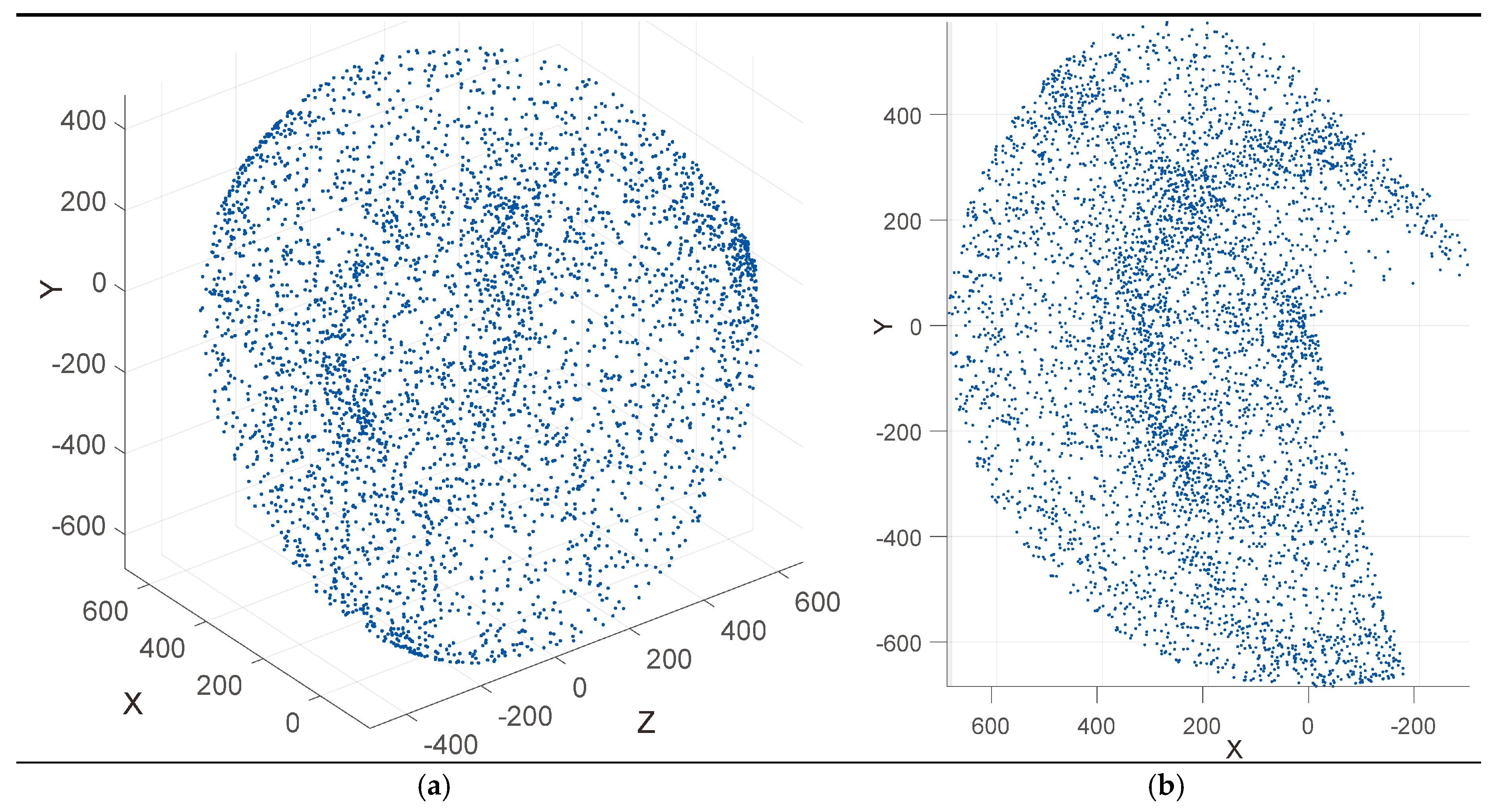
The workspace of the right arm of the 5-DOF upper-limb exoskeleton (mm): (a) Isometric view; and (b) right view.
Figure 7.
The workspace of the right arm of the 5-DOF upper-limb exoskeleton (mm): (a) Isometric view; and (b) right view.

Figure 8.
Inverse kinematics workspace (mm): (a) Isometric view; and (b) right view.

Figure 9.
End-effector trajectory: (a) Raising-up; and (b) Lateral-lifting.

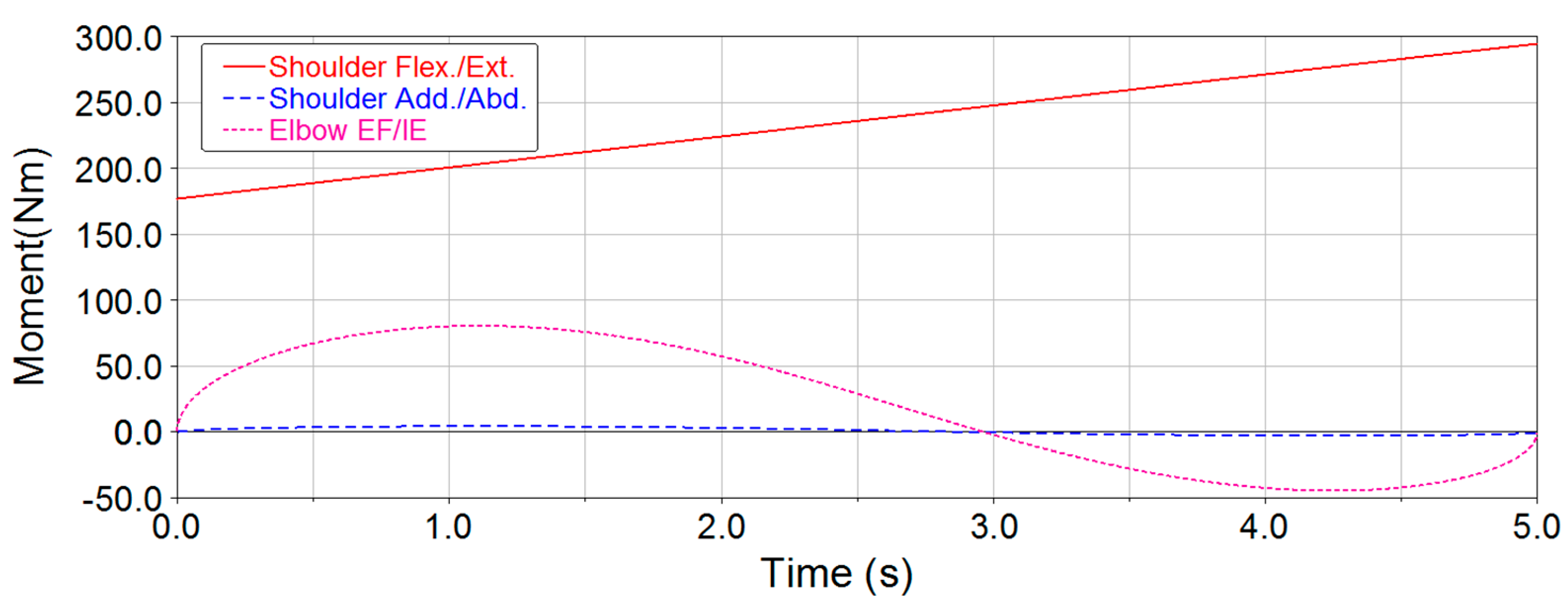
Figure 10.
Joint torque curves of raising up for the 3-DOF exoskeleton.

Figure 11.
Joint torque curves of raising up for the 5-DOF exoskeleton.

Figure 12.
Joint torque curves of lateral lifting for the 3-DOF exoskeleton.

Figure 13.
Joint torque curves of lateral lifting for the 5-DOF exoskeleton.

Figure 14.
Joint power consumption curves of raising up for the 3-DOF exoskeleton.

Figure 15.
Joint power consumption curves of raising up for the 5-DOF exoskeleton.

Figure 16.
Joint power consumption curves of lateral lifting for the 3-DOF exoskeleton.

Figure 17.
Joint power consumption curves of lateral lifting for the 5-DOF exoskeleton.

Figure 18.
Manufactured exoskeleton prototype: (a) 5-DOF; and (b) 3-DOF.

Figure 19.
Maximum ulnar deviation position of the 3-DOF exoskeleton prototype.

Figure 20.
Singularity position of the 5-DOF exoskeleton prototype.

Figure 21.
Schematic of the experiment.

Figure 22.
A complete hanging action: 3-DOF (a–g), 5-DOF (h–n).

Figure 23.
Statistical analysis results of the action completion time.


Table 1.
Motion range of human joints.
| Motion | Range |
|---|---|
| Shoulder flexion (Flex.)/extension (Ext.) | 180°/50° |
| Shoulder adduction (Add.)/abduction (Abd.) | 180°/0° |
| Shoulder internal (Int.)/external-rotation (Ext. Rot) | 90°/90° |
| Elbow flexion (Flex.)/extension (Ext.) | 0°/145 |
| Palmar flexion/dorsiflexion | 90°/70° |
| Ulnar deviation/radial deviation | 55°/25° |
| Wrist pronation (Pron.)/supination (Sup.) | 90°/90° |
Table 2.
Motion range of 5-DOF upper-limb exoskeleton.
| Motion | Range |
|---|---|
| Shoulder Flex./Ext. | 135°/15° |
| Shoulder Add./Abd. | 90°/30° |
| Shoulder Int./Ext. Rot | 90°/30° |
| Elbow Flex./Ext. | 118°/0° |
| Elbow Pron./Sup. | 30°/30° |
Table 3.
Function of the DOFs of the 5-DOF upper-limb exoskeleton.
| Motion | Function |
|---|---|
| Shoulder Flex./Ext. | Complete lifting, pull down, etc., which require the upper-limb to swing back and forth. |
| Shoulder Add./Abd. | Complete side lifting, etc., which require the upper-limb to swing lateral. |
| Shoulder Int./Ext. Rot | Increase the workspace of the upper-limb. |
| Elbow Flex./Ext. | Complete lifting, pull down, etc., which require the upper-limb to swing back and forth. |
| Elbow Pron./Sup. | Increase the flexibility of the end-effector. |
Table 4.
Motion range of the 3-DOF upper-limb exoskeleton.
| Configration | Motion | Range |
|---|---|---|
| 3-DOF | Shoulder Flex./Ext. | 180°/50° |
| Shoulder Add./Abd. | 180°/30° | |
| Elbow EF/IE | 118°/0° |
Table 5.
DH parameters of the 5-DOF upper-limb exoskeleton.
| Links | ||||
|---|---|---|---|---|
| 1 | 0° | 0 | 0 | |
| 2 | −90° | 0 | ||
| 3 | −90° | 0 | ||
| 4 | −90° | 0 | 0 |
Table 6.
DH parameters of the 3-DOF upper-limb exoskeleton.
| Links | ||||
|---|---|---|---|---|
| 1 | 0 | 0 | 0 | |
| 2 | −90° | 0 | ||
| 3 | 0 | 0 |
Table 7.
Inverse kinematics extremum of the 3-DOF upper-limb exoskeleton.
| Motion | Motion Range | |
|---|---|---|
| Inverse Kinematics Extremum | Range | |
| 90°/−105° | 180°/15° | |
| 29°/−104° | 29°/104° | |
| 123°/12° | 123°/12° | |
Table 8.
Parameters of the end-effector trajectory.
| Action | Parameters | Data |
|---|---|---|
| Raising up | 1500 mm | |
| 883 mm | ||
| 1931 mm | ||
| Lateral lifting | 1500 mm | |
| 350 mm | ||
| 30° |
Table 9.
Maximum joint torques.
| Configration | Motion | Maximum Joint Torque (Nm) |
|---|---|---|
| 5-DOF | Shoulder Flex./Ext. | 295 |
| Shoulder Add./Abd. | 185 | |
| Shoulder Int./Ext. Rot | 0 | |
| Elbow Flex./Ext. | 192 | |
| Elbow Pron./Sup. | 0 | |
| 3-DOF | Shoulder Flex./Ext. | 295 |
| Shoulder Add./Abd. | 185 | |
| Elbow EF/IE | 96 |
Table 10.
Maximum joint power consumption.
| Configration | Motion | Maximum Joint Power Consumption (W) |
|---|---|---|
| 3-DOF | Shoulder Flex./Ext. | 113.3 |
| Shoulder Add./Abd. | 3.4 | |
| Elbow EF/IE | 68.3 | |
| 5-DOF | Shoulder Flex./Ext. | 210.4 |
| Shoulder Add./Abd. | 0 | |
| Shoulder Int./Ext. Rot | 0 | |
| Elbow Flex./Ext. | 153.4 |
© 2018 by the authors. Licensee MDPI, Basel, Switzerland. This article is an open access article distributed under the terms and conditions of the Creative Commons Attribution (CC BY) license (http://creativecommons.org/licenses/by/4.0/).
Share and Cite
MDPI and ACS Style
Wang, X.; Song, Q.; Wang, X.; Liu, P. Kinematics and Dynamics Analysis of a 3-DOF Upper-Limb Exoskeleton with an Internally Rotated Elbow Joint. Appl. Sci. 2018, 8, 464. https://doi.org/10.3390/app8030464
AMA Style
Wang X, Song Q, Wang X, Liu P. Kinematics and Dynamics Analysis of a 3-DOF Upper-Limb Exoskeleton with an Internally Rotated Elbow Joint. Applied Sciences. 2018; 8(3):464. https://doi.org/10.3390/app8030464
Chicago/Turabian StyleWang, Xin, Qiuzhi Song, Xiaoguang Wang, and Pengzhan Liu. 2018. "Kinematics and Dynamics Analysis of a 3-DOF Upper-Limb Exoskeleton with an Internally Rotated Elbow Joint" Applied Sciences 8, no. 3: 464. https://doi.org/10.3390/app8030464
Note that from the first issue of 2016, this journal uses article numbers instead of page numbers. See further details here.