Frequency Comb-Based WDM Transmission Systems Enabling Joint Signal Processing

 , , , , , and
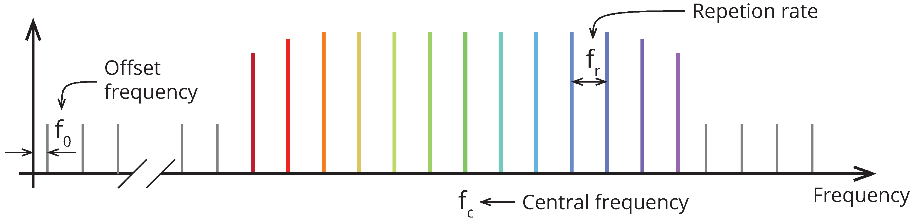
Abstract
:1. Introduction
1.1. Optical Frequency Combs: A Background
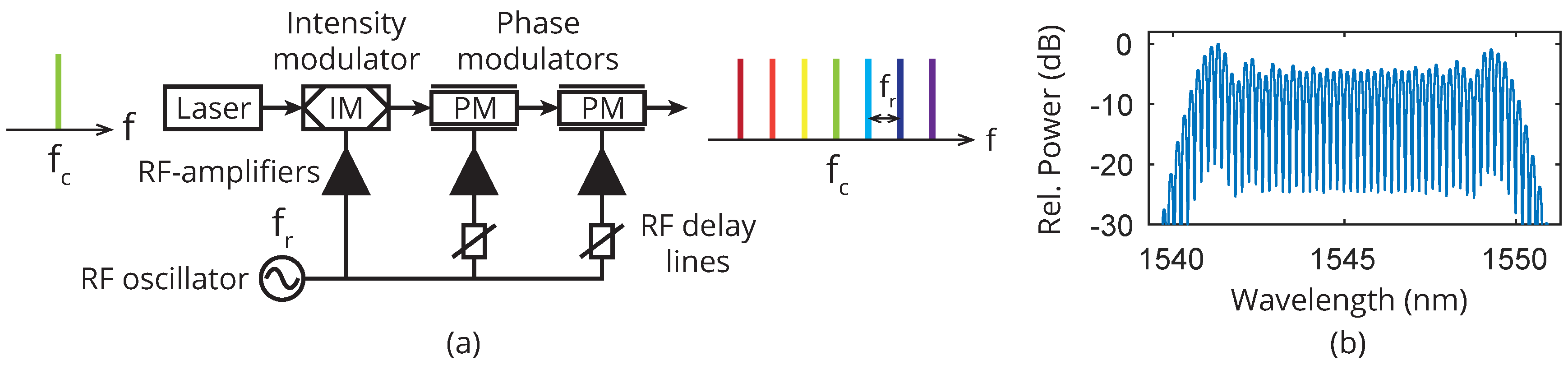
1.1.1. Technologies for Optical Frequency Comb Generation
1.1.2. Integration Potential of Frequency Combs
1.2. Unique Comb Benefits
- They enable the WDM channels to be more densely packed, requiring smaller guard bands between the channels, since they drift in frequency in a correlated manner, in contrast to separate laser sources. Such comb-based superchannels will be discussed in Section 2.
- They enable optical pilot signals that can be co-transmitted with the data with unprecedented low overhead, since two pilots are sufficient to regenerate a local-oscillator comb phase-locked to the transmitter comb for 50 WDM channels or more. Such pilot-based comb regeneration will be discussed in Section 3.
- They enable joint digital signal processing with reduced complexity or increased phase-noise tolerance, since the retrieved phase from one channel can be reused for the other channels or used to increase the SNR of the phase estimate. Such joint signal processing algorithms will be discussed in Section 4.
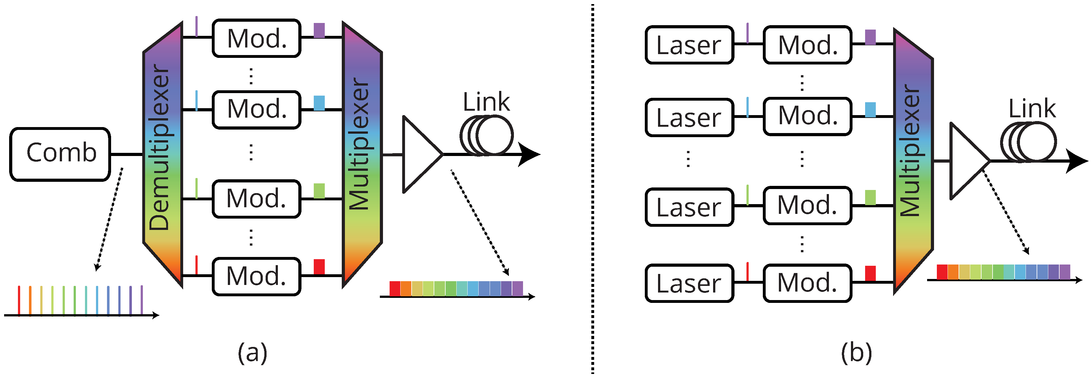
2. Comb-Based Superchannels
2.1. Superchannel Transmitter Requirements
2.1.1. OSNR Requirements
2.1.2. Guard Bands
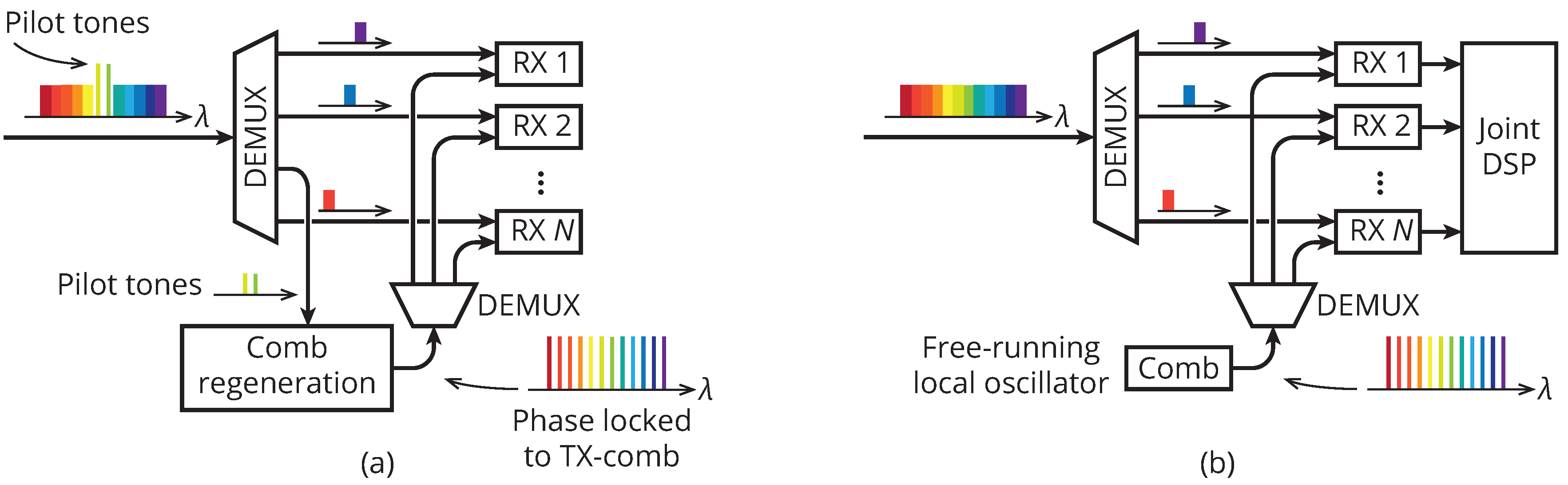
3. Receiver Comb Technologies
3.1. Exploiting Subchannel Phase Coherence
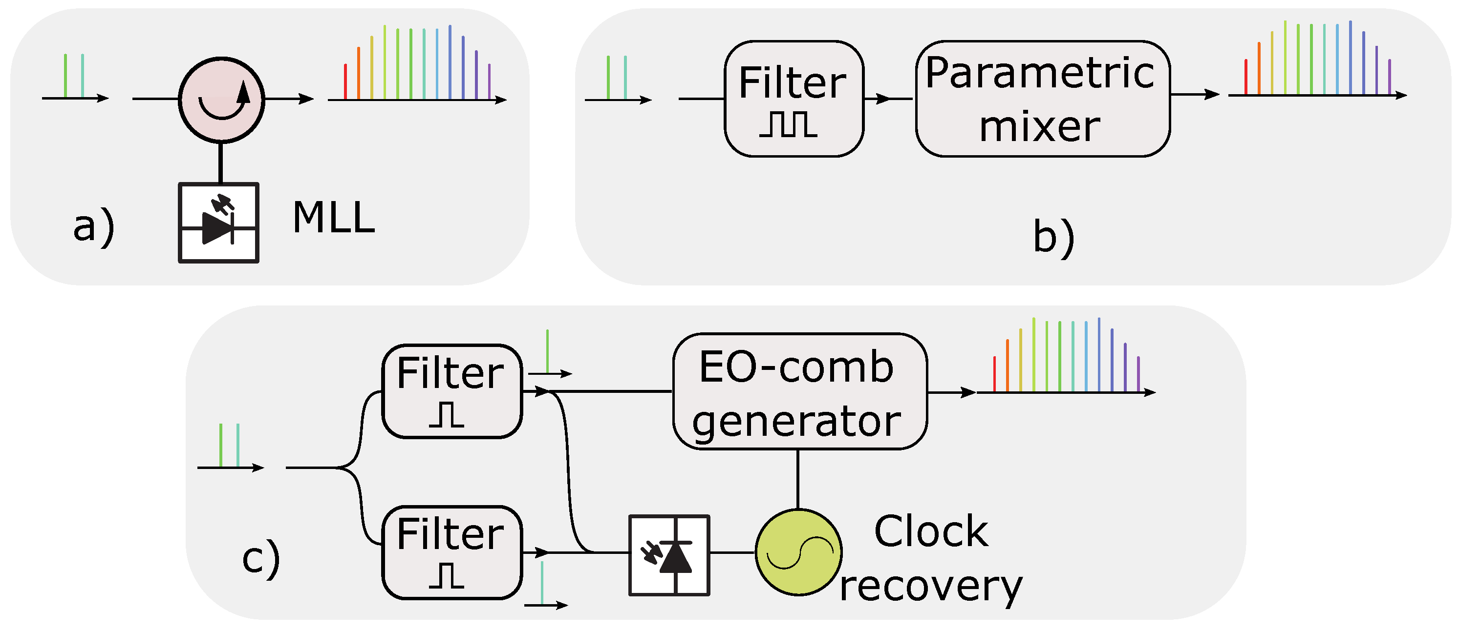
3.2. Regeneration from Two Pilots
3.3. Regeneration from a Single Pilot
3.4. Effects of Dispersion and Noise
4. Joint Digital Signal Processing Schemes for Carrier Recovery
4.1. Algorithms for Joint Carrier Recovery
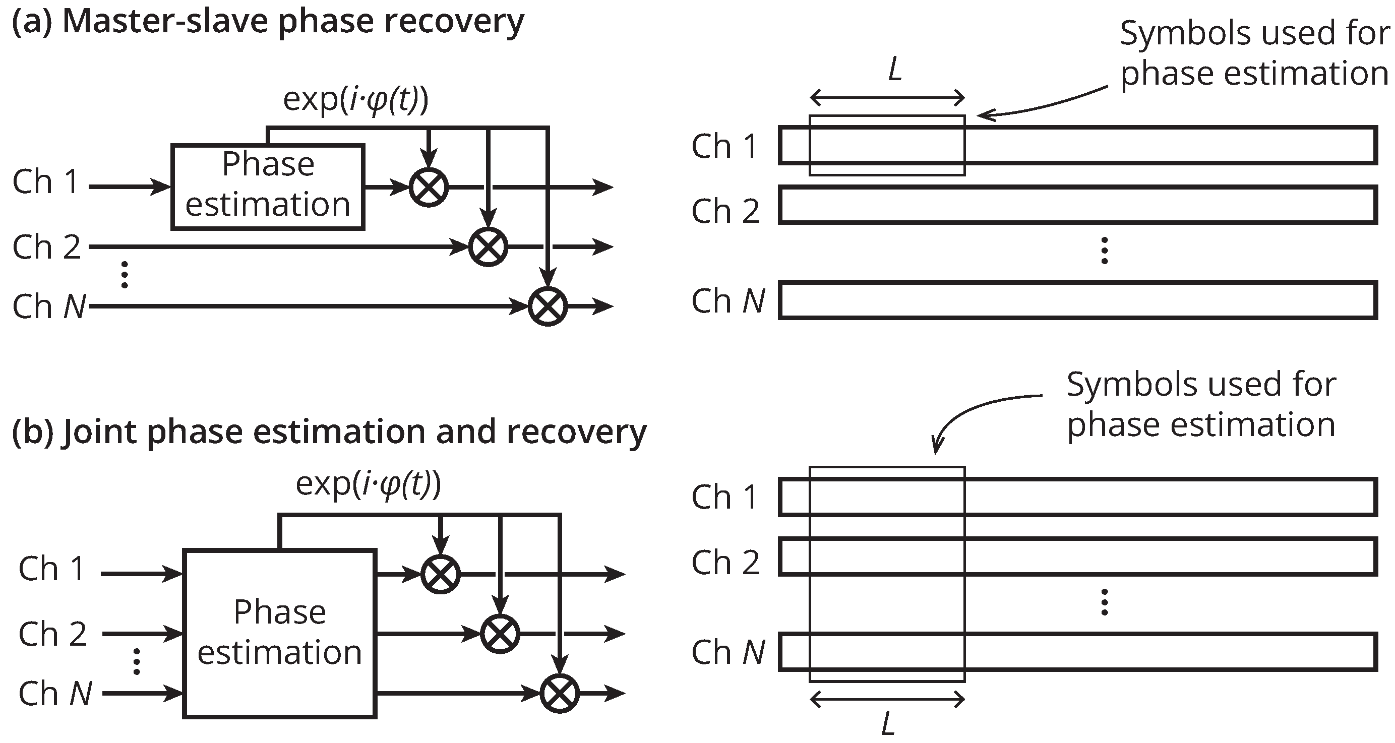
4.1.1. Master-Slave Carrier Recovery
4.1.2. Joint Phase Estimation
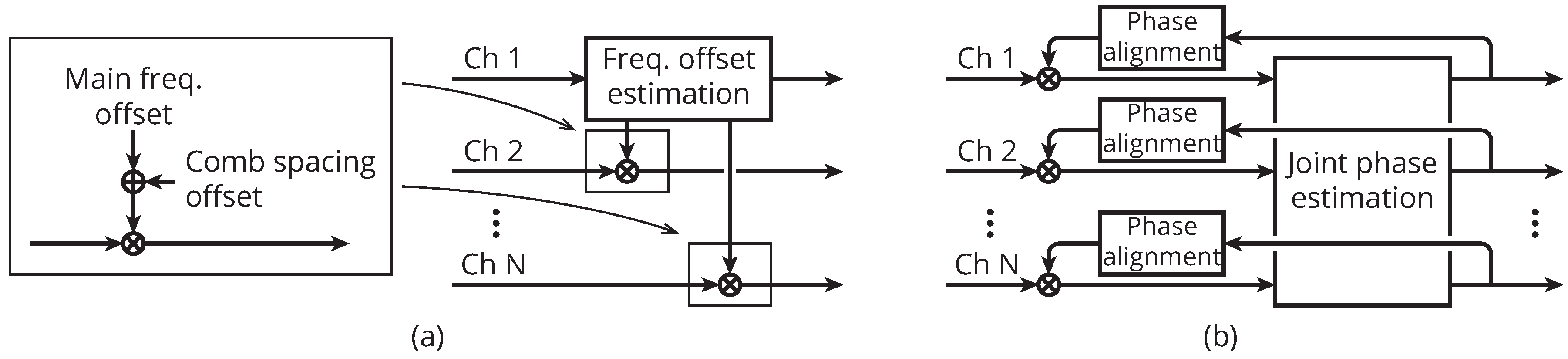
4.1.3. Managing Channel Phase Differences
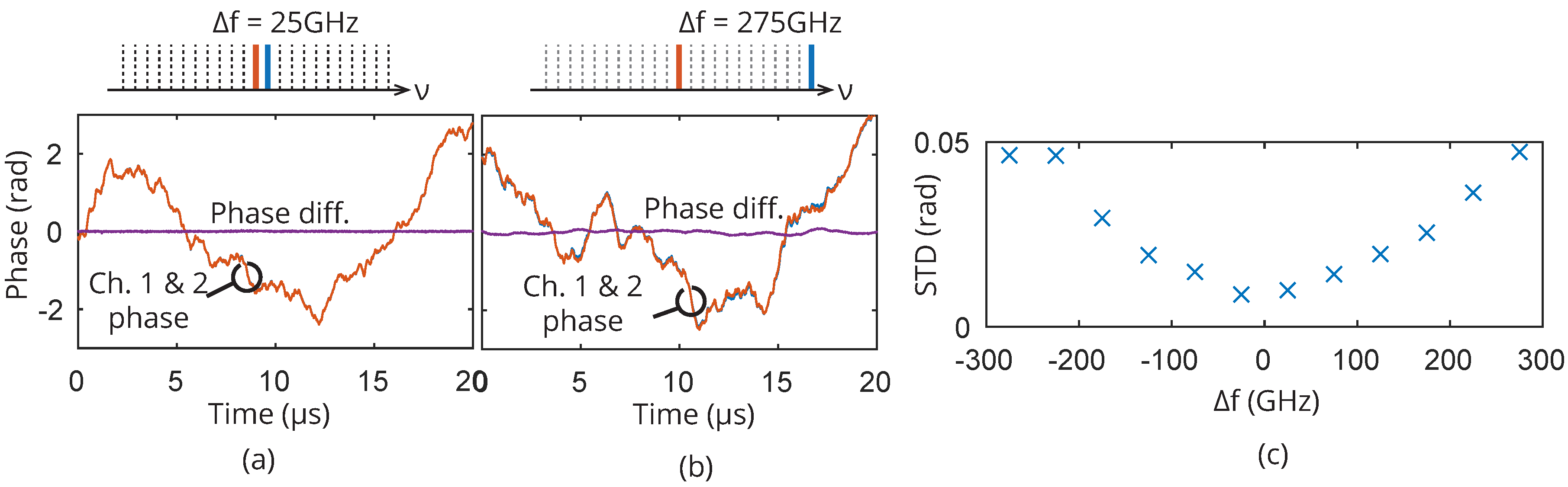
4.2. Transmission Effects
4.3. Experimental Evaluation
4.3.1. Master-Slave
4.3.2. Joint Estimation
5. Conclusions and Outlook
5.1. Comparison of the Methods in This Paper
5.2. Future Outlook
Author Contributions
Acknowledgments
Conflicts of Interest
References
- Mears, R.; Reekie, L.; Jauncey, I.; Payne, D. Low-noise erbium-doped fibre amplifier operating at 1.54 μm. Electron. Lett. 1987, 23, 1026–1028. [Google Scholar] [CrossRef]
- Desurvire, E.; Simpson, J.R.; Becker, P.C. High-gain erbium-doped traveling-wave fiber amplifier. Opt. Lett. 1987, 12, 888–890. [Google Scholar] [CrossRef] [PubMed]
- Fishman, D.A.; Nagel, J.A.; Cline, T.W.; Tench, R.E.; Pleiss, T.C.; Miller, T.; Coult, D.G.; Milbrodt, M.A.; Yeates, P.D.; Chraplyvy, A.; et al. A high capacity noncoherent FSK light wave field experiment using Er3+-doped fiber optical amplifiers. IEEE Photon. Technol. Lett. 1990, 2, 662–664. [Google Scholar] [CrossRef]
- Taga, H.; Yoshida, Y.; Edagawa, N.; Yamamoto, S.; Wakabayashi, H. 459 km, 2.4 Gbit/s four wavelength multiplexing optical fibre transmission experiment using six Er-doped fibre amplifiers. Electron. Lett. 1990, 26, 500–501. [Google Scholar] [CrossRef]
- Bergano, N.S. Wavelength division multiplexing in long-haul transoceanic transmission systems. J. Lightw. Technol. 2005, 23, 4125–4139. [Google Scholar] [CrossRef]
- Cai, J.X.; Batshon, H.G.; Mazurczyk, M.; Sinkin, O.V.; Wang, D.; Paskov, M.; Patterson, W.; Davidson, C.; Corbett, P.; Wolter, G.; et al. 70.46 Tb/s over 7600 km and 71.65 Tb/s over 6970 km Transmission in C+ L Band Using Coded Modulation with Hybrid Constellation Shaping and Nonlinearity Compensation. J. Lightw. Technol. 2017, 36, 114–121. [Google Scholar] [CrossRef]
- Derr, F. Coherent optical QPSK intradyne system: Concept and digital receiver realization. J. Lightw. Technol. 1992, 10, 1290–1296. [Google Scholar] [CrossRef]
- Sun, H.; Wu, K.; Roberts, K. Real-time measurements of a 40 Gb/s coherent system. Opt. Exp. 2008, 16, 873–879. [Google Scholar] [CrossRef]
- Kobayashi, T.; Sueta, T.; Cho, Y.; Matsuo, Y. High-repetition-rate optical pulse generator using a Fabry-Perot electro-optic modulator. Appl. Phys. Lett. 1972, 21, 341–343. [Google Scholar] [CrossRef]
- Kobayashi, T.; Yao, H.; Amano, K.; Fukushima, Y.; Morimoto, A.; Sueta, T. Optical pulse compression using high-frequency electrooptic phase modulation. IEEE J. Quantum Electron. 1988, 24, 382–387. [Google Scholar] [CrossRef]
- Metcalf, A.J.; Torres-Company, V.; Leaird, D.E.; Weiner, A.M. High-Power Broadly Tunable Electrooptic Frequency Comb Generator. IEEE J. Sel. Top. Quantum Electron. 2013, 19, 231–236. [Google Scholar] [CrossRef]
- Wu, R.; Supradeepa, V.R.; Long, C.M.; Leaird, D.E.; Weiner, A.M. Generation of very flat optical frequency combs from continuous-wave lasers using cascaded intensity and phase modulators driven by tailored radio frequency waveforms. Opt. Lett. 2010, 35, 3234. [Google Scholar] [CrossRef] [PubMed] [Green Version]
- Weiner, A.; Metcalf, A.; Diddams, S.; Fortier, T.; Quinlan, F. Broadly tunable, low timing jitter, high repetition rate optoelectronic comb generator. Electron. Lett. 2015, 51, 1596–1598. [Google Scholar]
- Keller, U. Recent developments in compact ultrafast lasers. Nature 2003, 424, 831–838. [Google Scholar] [CrossRef] [PubMed]
- Ranka, J.K.; Windeler, R.S.; Stentz, A.J. Visible continuum generation in air–silica microstructure optical fibers with anomalous dispersion at 800 nm. Opt. Lett. 2000, 25, 25. [Google Scholar] [CrossRef] [PubMed]
- Jones, D.J.; Diddams, S.A.; Ranka, J.K.; Stentz, A.; Windeler, R.S.; Hall, J.L.; Cundiff, S.T. Carrier-Envelope Phase Control of Femtosecond Mode-Locked Lasers and Direct Optical Frequency Synthesis. Science 2000, 288, 635–639. [Google Scholar] [CrossRef] [PubMed]
- Holzwarth, R.; Udem, T.; Hänsch, T.W.; Knight, J.C.; Wadsworth, W.J.; Russell, P.S.J. Optical Frequency Synthesizer for Precision Spectroscopy. Phys. Rev. Lett. 2000, 85, 2264–2267. [Google Scholar] [CrossRef] [PubMed]
- Morioka, T.; Takara, H.; Kawanishi, S.; Kamatani, O.; Takiguchi, K.; Uchiyama, K.; Saruwatari, M.; Takahashi, H.; Yamada, M.; Kanamori, T.; et al. 1 Tbit/s (100 Gbit/s times 10 channel) OTDM/WDM transmission using a single supercontinuum WDM source. Electron. Lett. 1996, 32, 906–907. [Google Scholar] [CrossRef]
- Veselka, J.; Korotky, S. A multiwavelength source having precise channel spacing for WDM systems. IEEE Photon. Technol. Lett. 1998, 10, 958–960. [Google Scholar] [CrossRef]
- Ohara, T.; Takara, H.; Yamamoto, T.; Masuda, H.; Morioka, T.; Abe, M.; Takahashi, H. Over-1000-channel ultradense WDM transmission with supercontinuum multicarrier source. J. Lightw. Technol. 2006, 24, 2311–2317. [Google Scholar] [CrossRef]
- Ishizawa, A.; Nishikawa, T.; Mizutori, A.; Takara, H.; Aozasa, S.; Mori, A.; Nakano, H.; Takada, A.; Koga, M. Octave-spanning frequency comb generated by 250 fs pulse train emitted from 25 GHz externally phase-modulated laser diode for carrier-envelope-offset-locking. Electron. Lett. 2010, 46, 1343–1344. [Google Scholar] [CrossRef]
- Jiang, Z.; Huang, C.B.; Leaird, D.E.; Weiner, A.M. Optical arbitrary waveform processing of more than 100 spectral comb lines. Nat. Photon. 2007, 1, 463–467. [Google Scholar] [CrossRef]
- Ataie, V.; Temprana, E.; Liu, L.; Myslivets, E.; Kuo, B.P.P.; Alic, N.; Radic, S. Ultrahigh Count Coherent WDM Channels Transmission Using Optical Parametric Comb-Based Frequency Synthesizer. J. Lightw. Technol. 2015, 33, 694–699. [Google Scholar] [CrossRef]
- Kuo, B.P.; Myslivets, E.; Ataie, V.; Temprana, E.G.; Alic, N.; Radic, S. Wideband Parametric Frequency Comb as Coherent Optical Carrier. J. Lightw. Technol. 2013, 31, 3414–3419. [Google Scholar] [CrossRef]
- Wu, R.; Torres-Company, V.; Leaird, D.E.; Weiner, A.M. Supercontinuum-based 10-GHz flat-topped optical frequency comb generation. Opt. Exp. 2013, 21, 6045–6052. [Google Scholar] [CrossRef] [PubMed]
- Temprana, E.; Ataie, V.; Kuo, B.P.P.; Myslivets, E.; Alic, N.; Radic, S. Low-noise parametric frequency comb for continuous C-plus-L-band 16-QAM channels generation. Opt. Exp. 2014, 22, 6822–6828. [Google Scholar] [CrossRef] [PubMed]
- Gnauck, A.H.; Kuo, B.P.P.; Myslivets, E.; Jopson, R.M.; Dinu, M.; Simsarian, J.E.; Winzer, P.J.; Radic, S. Comb-Based 16-QAM Transmitter Spanning the C and L Bands. IEEE Photon. Technol. Lett. 2014, 26, 821–824. [Google Scholar] [CrossRef]
- Puttnam, B.J.; Luis, R.S.; Klaus, W.; Sakaguchi, J.; Delgado Mendinueta, J.M.; Awaji, Y.; Wada, N.; Tamura, Y.; Hayashi, T.; Hirano, M.; et al. 2.15 Pb/s transmission using a 22 core homogeneous single-mode multi-core fiber and wideband optical comb. In Proceedings of the European Conference on Optical Communication (ECOC), Valencia, Spain, 27 September–1 October 2015; p. PDP.3.1. [Google Scholar]
- Wang, Z.; Van Gasse, K.; Moskalenko, V.; Latkowski, S.; Bente, E.; Kuyken, B.; Roelkens, G. A III-V-on-Si ultra-dense comb laser. Light Sci. Appl. 2017, 6, e16260. [Google Scholar] [CrossRef]
- Rafailov, E.U.; Cataluna, M.A.; Sibbett, W. Mode-locked quantum-dot lasers. Nat. Photon. 2007, 1, 395–401. [Google Scholar] [CrossRef]
- Lu, Z.; Liu, J.; Poole, P.; Song, C.; Chang, S. Ultra-narrow linewidth quantum dot coherent comb lasers. In Proceedings of the Optical Fiber Communication Conference (OFC), San Diego, CA, USA, 11–15 March 2018; p. Th1I.5. [Google Scholar]
- Srinivasan, S.; Davenport, M.; Heck, M.J.R.; Hutchinson, J.; Norberg, E.; Fish, G.; Bowers, J. Low phase noise hybrid silicon mode-locked lasers. Front. Optoelectron. 2014, 7, 265–276. [Google Scholar] [CrossRef]
- Roelkens, G.; Abassi, A.; Cardile, P.; Dave, U.; de Groote, A.; de Koninck, Y.; Dhoore, S.; Fu, X.; Gassenq, A.; Hattasan, N.; et al. III-V-on-Silicon Photonic Devices for Optical Communication and Sensing. Photonics 2015, 2, 969–1004. [Google Scholar] [CrossRef] [Green Version]
- Vujicic, V.; Calo, C.; Watts, R.; Lelarge, F.; Browning, C.; Merghem, K.; Martinez, A.; Ramdane, A.; Barry, L.P. Quantum Dash Mode-Locked Lasers for Data Centre Applications. IEEE J. Sel. Top. Quantum Electron. 2015, 21, 53–60. [Google Scholar] [CrossRef]
- Marin, P.; Pfeifle, J.; Kemal, J.N.; Wolf, S.; Vijayan, K.; Chimot, N.; Martinez, A.; Ramdane, A.; Lelarge, F.; Freude, W.; et al. 8.32 Tbit/s coherent transmission using a quantum-dash mode-locked laser diode. In Proceedings of the Conference on Lasers and Electro-Optics (CLEO), San Jose, CA, USA, 5–10 June 2016; p. STh1F.1. [Google Scholar]
- Kemal, J.N.; Marin-Palomo, P.; Merghem, K.; Aubin, G.; Calo, C.; Brenot, R.; Lelarge, F.; Ramdane, A.; Randel, S.; Freude, W.; et al. 32QAM WDM transmission using a quantum-dash passively mode-locked laser with resonant feedback. In Proceedings of the Optical Fiber Communication Conference (OFC), Los Angeles, CA, USA, 19–23 March 2017; p. Th5C.3. [Google Scholar]
- Zhou, R.; Huynh, T.N.; Vujicic, V.; Anandarajah, P.M.; Barry, L.P. Phase noise analysis of injected gain switched comb source for coherent communications. Opt. Exp. 2014, 22, 8120. [Google Scholar] [CrossRef] [PubMed]
- Gutierrez Pascual, M.D.; Vujicic, V.; Braddell, J.; Smyth, F.; Anandarajah, P.M.; Barry, L.P. InP photonic integrated externally injected gain switched optical frequency comb. Opt. Lett. 2017, 42, 555. [Google Scholar] [CrossRef] [PubMed]
- Kippenberg, T.J.; Holzwarth, R.; Diddams, S.A. Microresonator-Based Optical Frequency Combs. Science 2011, 332, 555–559. [Google Scholar] [CrossRef] [PubMed]
- Del’Haye, P.; Schliesser, A.; Arcizet, O.; Wilken, T.; Holzwarth, R.; Kippenberg, T.J. Optical frequency comb generation from a monolithic microresonator. Nature 2007, 450, 1214–1217. [Google Scholar] [CrossRef] [PubMed]
- Levy, J.S.; Gondarenko, A.; Foster, M.A.; Turner-Foster, A.C.; Gaeta, A.L.; Lipson, M. CMOS-compatible multiple-wavelength oscillator for on-chip optical interconnects. Nat. Photon. 2010, 4, 37–40. [Google Scholar] [CrossRef]
- Huang, S.W.; Zhou, H.; Yang, J.; McMillan, J.F.; Matsko, A.; Yu, M.; Kwong, D.L.; Maleki, L.; Wong, C.W. Mode-Locked Ultrashort Pulse Generation from On-Chip Normal Dispersion Microresonators. Phys. Rev. Lett. 2015, 114, 053901. [Google Scholar] [CrossRef] [PubMed]
- Pfeiffer, M.H.P.; Kordts, A.; Brasch, V.; Zervas, M.; Geiselmann, M.; Jost, J.D.; Kippenberg, T.J. Photonic Damascene process for integrated high-Q microresonator based nonlinear photonics. Optica 2016, 3, 20–25. [Google Scholar] [CrossRef]
- Xuan, Y.; Liu, Y.; Varghese, L.T.; Metcalf, A.J.; Xue, X.; Wang, P.H.; Han, K.; Jaramillo-Villegas, J.A.; Al Noman, A.; Wang, C.; et al. High-Q silicon nitride microresonators exhibiting low-power frequency comb initiation. Optica 2016, 3, 1171–1180. [Google Scholar] [CrossRef]
- Ji, X.; Barbosa, F.A.S.; Roberts, S.P.; Dutt, A.; Cardenas, J.; Okawachi, Y.; Bryant, A.; Gaeta, A.L.; Lipson, M. Ultra-low-loss on-chip resonators with sub-milliwatt parametric oscillation threshold. Optica 2017, 4, 619–624. [Google Scholar] [CrossRef]
- Li, Q.; Briles, T.C.; Westly, D.A.; Drake, T.E.; Stone, J.R.; Ilic, B.R.; Diddams, S.A.; Papp, S.B.; Srinivasan, K. Stably accessing octave-spanning microresonator frequency combs in the soliton regime. Optica 2017, 4, 193–203. [Google Scholar] [CrossRef] [PubMed]
- Levy, J.S.; Saha, K.; Okawachi, Y.; Foster, M.A.; Gaeta, A.L.; Lipson, M. High-Performance Silicon-Nitride-Based Multiple-Wavelength Source. IEEE Photon. Technol. Lett. 2012, 24, 1375–1377. [Google Scholar] [CrossRef]
- Pfeifle, J.; Brasch, V.; Lauermann, M.; Yu, Y.; Wegner, D.; Herr, T.; Hartinger, K.; Schindler, P.; Li, J.; Hillerkuss, D.; et al. Coherent terabit communications with microresonator Kerr frequency combs. Nat. Photon. 2014, 8, 375–380. [Google Scholar] [CrossRef] [PubMed]
- Wang, P.H.; Ferdous, F.; Miao, H.; Wang, J.; Leaird, D.E.; Srinivasan, K.; Chen, L.; Aksyuk, V.; Weiner, A.M. Observation of correlation between route to formation, coherence, noise, and communication performance of Kerr combs. Opt. Exp. 2012, 20, 29284–29295. [Google Scholar] [CrossRef] [PubMed]
- Fülöp, A.; Mazur, M.; Lorences-Riesgo, A.; Eriksson, T.A.; Wang, P.H.; Xuan, Y.; Leaird, D.E.; Qi, M.; Andrekson, P.A.; Weiner, A.M.; et al. Long-haul coherent communications using microresonator-based frequency combs. Opt. Exp. 2017, 25, 26678–26688. [Google Scholar] [CrossRef] [PubMed]
- Herr, T.; Brasch, V.; Jost, J.D.; Wang, C.Y.; Kondratiev, N.M.; Gorodetsky, M.L.; Kippenberg, T.J. Temporal solitons in optical microresonators. Nat. Photon. 2014, 8, 145–152. [Google Scholar] [CrossRef]
- Marin-Palomo, P.; Kemal, J.N.; Karpov, M.; Kordts, A.; Pfeifle, J.; Pfeiffer, M.H.P.; Trocha, P.; Wolf, S.; Brasch, V.; Anderson, M.H.; et al. Microresonator-based solitons for massively parallel coherent optical communications. Nature 2017, 546, 274–279. [Google Scholar] [CrossRef] [PubMed]
- Liao, P.; Bao, C.; Kordts, A.; Karpov, M.; Pfeiffer, M.H.P.; Zhang, L.; Cao, Y.; Almaiman, A.; Mohajerin-Ariaei, A.; Tur, M.; et al. Pump-linewidth-tolerant wavelength multicasting using soliton Kerr frequency combs. Opt. Lett. 2017, 42, 3177–3180. [Google Scholar] [CrossRef] [PubMed]
- Bao, C.; Zhang, L.; Matsko, A.; Yan, Y.; Zhao, Z.; Xie, G.; Agarwal, A.M.; Kimerling, L.C.; Michel, J.; Maleki, L.; et al. Nonlinear conversion efficiency in Kerr frequency comb generation. Opt. Lett. 2014, 39, 6126–6129. [Google Scholar] [CrossRef] [PubMed]
- Xue, X.; Xuan, Y.; Liu, Y.; Wang, P.H.; Chen, S.; Wang, J.; Leaird, D.E.; Qi, M.; Weiner, A.M. Mode-locked dark pulse Kerr combs in normal-dispersion microresonators. Nat. Photon. 2015, 9, 594–600. [Google Scholar] [CrossRef]
- Xue, X.; Wang, P.H.; Xuan, Y.; Qi, M.; Weiner, A.M. Microresonator Kerr frequency combs with high conversion efficiency. Laser Phot. Rev. 2017, 11, 1600276. [Google Scholar] [CrossRef]
- Fülöp, A.; Mazur, M.; Lorences-Riesgo, A.; Wang, P.H.; Xuan, Y.; Leaird, D.E.; Qi, M.; Andrekson, P.A.; Weiner, A.M.; Torres-Company, V. High-order coherent communications using mode-locked dark-pulse Kerr combs from microresonators. Nature Communications 2018, 8, 1598. [Google Scholar] [CrossRef] [PubMed]
- Matsko, A.B.; Maleki, L. On timing jitter of mode-locked Kerr frequency combs. Opt. Exp. 2013, 21, 28862–28876. [Google Scholar] [CrossRef] [PubMed]
- Liang, W.; Eliyahu, D.; Ilchenko, V.S.; Savchenkov, A.A.; Matsko, A.B.; Seidel, D.; Maleki, L. High spectral purity Kerr frequency comb radio frequency photonic oscillator. Nat. Commun. 2015, 6, 7957. [Google Scholar] [CrossRef] [PubMed]
- Yi, X.; Yang, Q.F.; Zhang, X.; Yang, K.Y.; Li, X.; Vahala, K. Single-mode dispersive waves and soliton microcomb dynamics. Nat. Commun. 2017, 8, 14869. [Google Scholar] [CrossRef] [PubMed]
- Takushima, Y.; Sotobayashi, H.; Grein, M.E.; Ippen, E.P.; Haus, H.A. Linewidth of mode combs of passively and actively mode-locked semiconductor laser diodes. Opt. East 2004, 5595, 213–227. [Google Scholar]
- Newbury, N.R. Searching for applications with a fine-tooth comb. Nat. Photon. 2011, 5, 186–188. [Google Scholar] [CrossRef]
- Lorences-Riesgo, A.; Eriksson, T.A.; Fülöp, A.; Andrekson, P.A.; Karlsson, M. Frequency-comb regeneration for self-homodyne superchannels. J. Lightw. Technol. 2016, 34, 1800–1806. [Google Scholar] [CrossRef]
- Lorences-Riesgo, A.; Mazur, M.; Eriksson, T.A.; Andrekson, P.A.; Karlsson, M. Self-homodyne 24×32-QAM superchannel receiver enabled by all-optical comb regeneration using Brillouin amplification. Opt. Exp. 2016, 24, 29714–29723. [Google Scholar] [CrossRef] [PubMed]
- Mazur, M.; Lorences-Riesgo, A.; Schroeder, J.; Andrekson, P.A.; Karlsson, M. 10 Tb/s PM-64QAM Self-Homodyne Comb-Based Superchannel Transmission with 4% Shared Pilot Tone Overhead. J. Lightw. Technol. 2018. [Google Scholar] [CrossRef]
- Lundberg, L.; Mazur, M.; Lorences-Riesgo, A.; Karlsson, M.; Andrekson, P.A. Joint Carrier Recovery for DSP Complexity Reduction in Frequency Comb-Based Superchannel Transceivers. In Proceedings of the European Conference on Optical Communication (ECOC), Gothenburg, Sweden, 17–21 September 2017; p. Th.1.D.3. [Google Scholar]
- Mazur, M.; Lorences-Riesgo, A.; Schröder, J.; Andrekson, P.; Karlsson, M. High Spectral Efficiency PM-128QAM Comb-Based Superchannel Transmission Enabled by a Single Shared Optical Pilot Tone. J. Lightw. Technol. 2017, 36, 1318–1325. [Google Scholar] [CrossRef]
- Mazur, M.; Schröder, J.; Lorences-Riesgo, A.; Yoshida, T.; Karlsson, M.; Andrekson, P.A. 11.5bits/s/Hz PM-256QAM Comb-based Superchannel Transmission by Combining Optical and Digital Pilots. In Proceedings of the Optical Fiber Communication Conference (OFC), San Diego, CA, USA, 11–15 March 2018; p. M1G.2. [Google Scholar]
- Fontaine, N.; Scott, R.P.; Zhou, L.; Soares, F.M.; Heritage, J.; Yoo, S. Real-time full-field arbitrary optical waveform measurement. Nat. Photon. 2010, 4, 248. [Google Scholar] [CrossRef]
- Fontaine, N. Spectrally-sliced Coherent Receivers for THz Bandwidth Optical Communications. In Proceedings of the European Conference on Optical Communication (ECOC), London, UK, 22–26 September 2013; p. Mo.3.C.1. [Google Scholar]
- Alic, N.; Myslivets, E.; Temprana, E.; Kuo, B.P.P.; Radic, S. Nonlinearity Cancellation in Fiber Optic Links Based on Frequency Referenced Carriers. J. Lightw. Technol. 2014, 32, 2690–2698. [Google Scholar] [CrossRef]
- Temprana, E.; Myslivets, E.; Kuo, B.P.; Liu, L.; Ataie, V.; Alic, N.; Radic, S. Overcoming Kerr-induced capacity limit in optical fiber transmission. Science 2015, 348, 1445–1448. [Google Scholar] [CrossRef] [PubMed]
- Chandrasekhar, S.; Liu, X.; Zhu, B.; Peckham, D. Transmission of a 1.2-Tb/s 24-carrier no-guard-interval coherent OFDM superchannel over 7200-km of ultra-large-area fiber. In Proceedings of the European Conference on Optical Communication (ECOC), Vienna, Austria, 20–24 September 2009. [Google Scholar]
- Winzer, P.J.; Neilson, D.T. From Scaling Disparities to Integrated Parallelism: A Decathlon for a Decade. J. Lightw. Technol. 2017, 35, 1099–1115. [Google Scholar] [CrossRef]
- Liu, X.; Chandrasekhar, S.; Winzer, P.J. Digital Signal Processing Techniques Enabling Multi-Tb/s Superchannel Transmission: An overview of recent advances in DSP-enabled superchannels. IEEE Signal Process. Mag. 2014, 31, 16–24. [Google Scholar] [CrossRef]
- Raybon, G.; Adamiecki, A.; Cho, J.; Jorge, F.; Konczykowska, A.; Riet, M.; Duval, B.; Dupuy, J.Y.; Fontaine, N.; Winzer, P.J.; et al. 180-GBaud All-ETDM Single-Carrier Polarization Multiplexed QPSK Transmission over 4480 km. In Proceedings of the Optical Fiber Communication Conference (OFC), San Diego, CA, USA, 11–15 March 2018; p. Th4C.3. [Google Scholar]
- Going, R.; Lauermann, M.; Maher, R.; Tsai, H.S.; Lu, M.; Kim, N.; Corzine, S.; Studenkov, P.; Summers, J.; Hosseini, A.; et al. Multi-channel InP-based coherent PICs with hybrid integrated SiGe electronics operating up to 100GBd, 32QAM. In Proceedings of the European Conference on Optical Communication (ECOC), Gothenburg, Sweden, 17–21 September 2017. [Google Scholar]
- Chandrasekhar, S.; Li, B.; Cho, J.; Chen, X.; Burrows, E.; Raybon, G.; Winzer, P. High-spectral-efficiency transmission of PDM 256-QAM with parallel probabilistic shaping at record rate-reach trade-offs. In Proceedings of the European Conference on Optical Communication (ECOC), Dusseldorf, Germany, 18–22 September 2016; p. Th.3.C.1. [Google Scholar]
- Agrawal, G.P. Fiber-Optic Communication Systems; John Wiley & Sons: Hoboken, NJ, USA, 2011. [Google Scholar]
- Kobayashi, N.; Sato, K.; Namiwaka, M.; Yamamoto, K.; Watanabe, S.; Kita, T.; Yamada, H.; Yamazaki, H. Silicon Photonic Hybrid Ring-Filter External Cavity Wavelength Tunable Lasers. J. Lightw. Technol. 2015, 33, 1241–1246. [Google Scholar] [CrossRef]
- Laperle, C.; Osullivan, M. Advances in high-speed DACs, ADCs, and DSP for optical coherent transceivers. J. Lightw. Technol. 2014, 32, 629–643. [Google Scholar] [CrossRef]
- Millar, D.S.; Maher, R.; Lavery, D.; Koike-Akino, T.; Pajovic, M.; Alvarado, A.; Paskov, M.; Kojima, K.; Parsons, K.; Thomsen, B.C.; et al. Design of a 1 Tb/s Superchannel Coherent Receiver. J. Lightw. Technol. 2016, 34, 1453–1463. [Google Scholar] [CrossRef]
- Maher, R.; Xu, T.; Galdino, L.; Sato, M.; Alvarado, A.; Shi, K.; Savory, S.J.; Thomsen, B.C.; Killey, R.I.; Bayvel, P. Spectrally shaped DP-16QAM super-channel transmission with multi-channel digital back-propagation. Sci. Rep. 2015, 5, 8214. [Google Scholar] [CrossRef] [PubMed]
- Puttnam, B.; Luís, R.; Delgado Mendinueta, J.; Sakaguchi, J.; Klaus, W.; Kamio, Y.; Nakamura, M.; Wada, N.; Awaji, Y.; Kanno, A.; et al. Self-Homodyne Detection in Optical Communication Systems. Photonics 2014, 1, 110–130. [Google Scholar] [CrossRef]
- Nakamura, M.; Kamio, Y.; Lu, G.W.; Miyazaki, T. Ultimate Linewidth-Tolerant 20-Gbps QPSK-Homodyne Transmission using a Spectrum-Sliced ASE Light Source. In Proceedings of the Optical Fiber Communication Conference (OFC), Anaheim, CA, USA, 25–29 March 2007; p. OThD4. [Google Scholar]
- Mendinueta, J.M.D.; Puttnam, B.J.; Sakaguchi, J.; Luis, R.S.; Klaus, W.; Awaji, Y.; Wada, N.; Kanno, A.; Kawanishi, T. Energy efficient carrier phase recovery for self-homodyne polarization-multiplexed QPSK. In Proceedings of the OptoElectronics and Communications Conference (OECC), Kyoto, Japan, 30 June–4 July 2013; p. ThR3.5. [Google Scholar]
- Luís, R.S.; Puttnam, B.J.; Mendinueta, J.M.D.; Shinada, S.; Nakamura, M.; Kamio, Y.; Wada, N. Digital Self-Homodyne Detection. IEEE Photon. Technol. Lett. 2015, 27, 608–611. [Google Scholar] [CrossRef]
- Le Taillandier de Gabory, E.; Arikawa, M.; Hashimoto, Y.; Ito, T.; Fukuchi, K. A Shared Carrier Reception and Processing Scheme for Compensating Frequency Offset and Phase Noise of Space-Division Multiplexed Signals over Multicore Fibers. In Proceedings of the Optical Fiber Communication Conference (OFC), Anaheim, CA, USA, 17–21 March 2013; p. OM2C.2. [Google Scholar]
- Delfyett, P.J.; Gee, S.; Choi, M.T.; Izadpanah, H.; Lee, W.; Ozharar, S.; Quinlan, F.; Yilmaz, T. Optical frequency combs from semiconductor lasers and applications in ultrawideband signal processing and communications. J. Lightw. Technol. 2006, 24, 2701–2719. [Google Scholar] [CrossRef]
- Kemal, J.N.; Pfeifle, J.; Marin-Palomo, P.; Pascual, M.D.G.; Wolf, S.; Smyth, F.; Freude, W.; Koos, C. Multi-wavelength coherent transmission using an optical frequency comb as a local oscillator. Opt. Exp. 2016, 24, 25432–25445. [Google Scholar] [CrossRef] [PubMed]
- Mori, K.; Hamaoka, F.; Horikoshi, K.; Fukutoku, M. Stable WDM-Signal-and-LO-frequency Synchronisation and Transmission Employing Multi-Carrier Light Sources and a Multi-Core Fibre for Coherent Photonic Networks. In Proceedings of the European Conference on Optical Communication (ECOC), Dusseldorf, Germany, 18–22 September 2016; p. Tu.1.C.3. [Google Scholar]
- Sakaguchi, J.; Awaji, Y.; Wada, N. Optimal Pilot-Tone-Aided Multi-Core Fiber Transmission Using a Wideband Comb Transmitter. IEEE Photon. Technol. Lett. 2017, 29, 1245–1248. [Google Scholar] [CrossRef]
- Fehenberger, T.; Hanik, N.; Eriksson, T.A.; Johannisson, P.; Karlsson, M. On the impact of carrier phase estimation on phase correlations in coherent fiber transmission. In Proceedings of the Tyrrhenian International Workshop on Digital Communications, Florence, Italy, 22 September 2015. [Google Scholar]
- Guiomar, F.P.; Carena, A.; Bosco, G.; Bertignono, L.; Nespola, A.; Poggiolini, P. Nonlinear mitigation on subcarrier-multiplexed PM-16QAM optical systems. Opt. Exp. 2017, 25, 4298–4311. [Google Scholar] [CrossRef] [PubMed]
- Sakaguchi, J.; Kumagai, M.; Li, Y.; Ido, T.; Awaji, Y.; Wada, N. DSP-complexity Reduction of QAM-based Coherent Optical Networks Enabled by Seed Lightwave Distribution. In Proceedings of the Conference on Lasers and Electro-Optics (CLEO), San Jose, CA, USA, 10–15 May 2015; p. SW1M.7. [Google Scholar]
- Sakaguchi, J.; Awaji, Y.; Wada, N. Seed Lightwave Distribution over 1600 km for 64QAM-Based Coherent WDM Optical Networks with Low DSP-complexity. In Proceedings of the European Conference on Optical Communication (ECOC), Dusseldorf, Germany, 18–22 September 2016; p. W.4.P1.SC5.12. [Google Scholar]
- Cruz, F.C. Optical frequency combs generated by four-wave mixing in optical fibers for astrophysical spectrometer calibration and metrology. Opt. Express 2008, 16, 13267–13275. [Google Scholar] [CrossRef] [PubMed]
- Noé, R. Phase noise-tolerant synchronous QPSK/BPSK baseband-type intradyne receiver concept with feedforward carrier recovery. J. Lightw. Technol. 2005, 23, 802–808. [Google Scholar] [CrossRef]
- Alfredsson, A.; Krishnan, R.; Agrell, E. Joint-Polarization Phase-Noise Estimation and Symbol Detection for Optical Coherent Receivers. J. Lightw. Technol. 2016, 34, 4394–4405. [Google Scholar] [CrossRef]
- Feuer, M.D.; Nelson, L.E.; Zhou, X.; Woodward, S.L.; Isaac, R.; Zhu, B.; Taunay, T.F.; Fishteyn, M.; Fini, J.M.; Yan, M.F. Joint Digital Signal Processing Receivers for Spatial Superchannels. IEEE Photon. Technol. Lett. 2012, 24, 1957–1960. [Google Scholar] [CrossRef]
- Van Uden, R.G.H.; Okonkwo, C.M.; Sleiffer, V.A.J.M.; Kuschnerov, M.; De Waardt, H.; Koonen, A.M.J. Single DPLL joint carrier phase compensation for few-mode fiber transmission. IEEE Photon. Technol. Lett. 2013, 25, 1381–1384. [Google Scholar] [CrossRef]
- Van Uden, R.G.H.; Okonkwo, C.M.; Chen, H.; De Waardt, H.; Koonen, A.M.J. 28-GBd 32QAM FMF transmission with low complexity phase estimators and single DPLL. IEEE Photon. Technol. Lett. 2014, 26, 765–768. [Google Scholar] [CrossRef]
- Liu, C.; Pan, J.; Detwiler, T.; Stark, A.; Hsueh, Y.T.; Chang, G.K.; Ralph, S.E. Joint digital signal processing for superchannel coherent optical communication systems. Opt. Exp. 2013, 21, 8342–8356. [Google Scholar] [CrossRef] [PubMed]
- Souto, D.V.; Olsson, B.E.; Larsson, C.; Mello, D.A.A. Joint-Polarization and Joint-Subchannel Carrier Phase Estimation for 16-QAM Optical Systems. J. Lightw. Technol. 2012, 30, 3185–3191. [Google Scholar] [CrossRef]
- Alfredsson, A.F.; Agrell, E.; Wymeersch, H.; Karlsson, M. Phase-Noise Compensation for Spatial-Division Multiplexed Transmission. In Proceedings of the Optical Fiber Communication Conference (OFC), Los Angeles, CA, USA, 19–23 March 2017; p. Th4C.7. [Google Scholar]
- Alfredsson, A.F.; Agrell, E.; Wymeersch, H.; Karlsson, M. Pilot Distributions for Phase Tracking in Space-Division Multiplexed Systems. In Proceedings of the European Conference on Optical Communication (ECOC), Gothenburg, Sweden, 17–21 September 2017; p. P1.SC3.48. [Google Scholar]
- Savory, S.J. Digital Coherent Optical Receivers: Algorithms and Subsystems. IEEE J. Sel. Top. Quantum Electron. 2010, 16, 1164–1179. [Google Scholar] [CrossRef]
- Pfau, T.; Hoffmann, S.; Noé, R. Hardware-Efficient Coherent Digital Receiver Concept With Feedforward Carrier Recovery for M-QAM Constellations. J. Lightw. Technol. 2009, 27, 989–999. [Google Scholar] [CrossRef]
- Proakis, J.G.; Salehi, M. Digital Communications, 5th ed.; McGraw-Hill Higher Education: New York, NY, USA, 2008. [Google Scholar]
- Slavik, R.; Farwell, S.G.; Wale, M.J.; Richardson, D.J. Compact Optical Comb Generator Using InP Tunable Laser and Push-Pull Modulator. IEEE Photon. Technol. Lett. 2015, 27, 217–220. [Google Scholar] [CrossRef]
- Zanette, K.; Cartledge, J.C.; O’Sullivan, M. Correlation properties of the phase noise between pairs of lines in a quantum-dot optical frequency comb source. In Proceedings of the Optical Fiber Communication Conference (OFC), Los Angeles, CA, USA, 19–23 March 2017; p. Th3I.6. [Google Scholar]
- Zanette, K.; Cartledge, J.C.; Hui, R.; O’Sullivan, M. Phase Noise Characterization of a Mode-Locked Quantum- Dot Coherent Optical Frequency Comb Source Laser. In Proceedings of the Optical Fiber Communication Conference (OFC), San Diego, CA, USA, 11–15 March 2018; p. Th2A.17. [Google Scholar]


© 2018 by the authors. Licensee MDPI, Basel, Switzerland. This article is an open access article distributed under the terms and conditions of the Creative Commons Attribution (CC BY) license (http://creativecommons.org/licenses/by/4.0/).
Share and Cite
Lundberg, L.; Karlsson, M.; Lorences-Riesgo, A.; Mazur, M.; Torres-Company, V.; Schröder, J.; Andrekson, P.A. Frequency Comb-Based WDM Transmission Systems Enabling Joint Signal Processing. Appl. Sci. 2018, 8, 718. https://doi.org/10.3390/app8050718
Lundberg L, Karlsson M, Lorences-Riesgo A, Mazur M, Torres-Company V, Schröder J, Andrekson PA. Frequency Comb-Based WDM Transmission Systems Enabling Joint Signal Processing. Applied Sciences. 2018; 8(5):718. https://doi.org/10.3390/app8050718
Chicago/Turabian StyleLundberg, Lars, Magnus Karlsson, Abel Lorences-Riesgo, Mikael Mazur, Victor Torres-Company, Jochen Schröder, and Peter A. Andrekson. 2018. "Frequency Comb-Based WDM Transmission Systems Enabling Joint Signal Processing" Applied Sciences 8, no. 5: 718. https://doi.org/10.3390/app8050718