Multibody Simulation for the Vibration Analysis of a Turbocharged Diesel Engine
by
 , , and
Enrico Armentani
1,* ,
,
Francesco Caputo
2,
Luca Esposito
3,
Venanzio Giannella
4 and
Roberto Citarella
4
1
Department of Chemical, Materials and Production Engineering, University of Naples Federico II, P.le V. Tecchio, 80, 80125 Napoli, Italy
2
Department of Engineering, University of Campania “Luigi Vanvitelli”, Via Roma, 29, 81031 Aversa (CE), Italy
3
Department of Industrial Engineering, University of Naples Federico II, P.le V. Tecchio, 80, 80125 Napoli, Italy
4
Department of Industrial Engineering, University of Salerno, Via Giovanni Paolo II, 132, 84084 Fisciano (SA), Italy
*
Author to whom correspondence should be addressed.
Appl. Sci. 2018, 8(7), 1192; https://doi.org/10.3390/app8071192
Submission received: 15 May 2018
/
Revised: 4 July 2018
/
Accepted: 17 July 2018
/
Published: 20 July 2018
(This article belongs to the Special Issue Aeroacustic and Vibroacoustic Advancement in Aerospace and Automotive Systems)
Abstract
:In this paper, a multibody calculation methodology has been applied to the vibration analysis of a 4-cylinder, 4-stroke, turbocharged diesel engine, with a simulation driven study of the angular speed variation of a crankshaft under consideration of different modeling assumptions. Moreover, time dependent simulation results, evaluated at the engine supports, are condensed to a vibration index and compared with experimental results, obtaining satisfactory outcomes. The modal analysis also considers the damping aspects and has been conducted using a multibody model created with the software AVL/EXCITE. The influence of crankshaft torsional frequencies on the rotational speed behavior has been evaluated in order to reduce the vibration phenomena. The focus of this work is related to industrial aspects since, for an existing and commercialized engine, a numerical and experimental complex study has been performed to enable design improvements aimed at reducing noise and vibrations. Existing procedures and algorithms are combined here to reach the abovementioned objectives in the most efficient way.
1. Introduction
Structural and acoustic modeling methods [1], used to predict the vibroacoustics and aeroacoustics performance of aerospace [2] and automotive systems, have become a key tool in the design process.
Car engine dynamics are explored especially in the low frequency range and at low engine speeds, where the direct vibration transmission by the engine mounts is a critical excitation mechanism, but raising the maximum analyzed frequency constitutes an important industrial challenge for automotive and aerospace industry.
There are several examples in the literature describing a combination of multi-body simulation, including flexible FE subsystems, to perform dynamics and acoustic simulation of mechanical components.
In [3], a multibody model of a valve train system for a car engine was developed in order to analyze its resonant vibrational behavior. The dynamics of the valve train system were analyzed, applying a ramp to the crankshaft with a variable engine speed and considering the motion unsmoothness deriving from the inertia and combustion pressure loads.
In [4] the development of a numerical model to predict the noise radiating from manual gearboxes due to gear rattle is provided. The measured data are used to identify and reproduce the input excitation that is primarily generated from engine combustion forces. The dynamic interaction of the gearbox components, including flywheel, input/output shafts, contacting gear-pairs, bearings, and flexible housing is modeled using flexible multibody techniques. The acoustic response to the vibration of the gearbox housing is then predicted using vibroacoustic techniques.
In [5,6] the numerical modeling of noise radiated by an engine and by a car body, respectively, using the so-called Acoustic Transfer Vectors and Modal Acoustic Transfer Vectors concepts is presented. The dynamics of the engine are described using a finite element model loaded with an RPM-dependent excitation.
In [7], a technique to compute the noise radiated by a large truck engine is presented: the vibration is computed using a commercial FEM code, whose results are subsequently used in an acoustic radiation computation.
In [8], a vibroacoustic numerical and experimental analysis was carried out for the chain cover of a low powered four-cylinder four-stroke diesel engine. A Boundary Element (BE) model of the chain cover was realized to determine the chain cover noise emission, starting from the previously calculated structural vibrations. The numerical vibroacoustic outcomes were compared with those observed experimentally, obtaining a good correlation.
In [9,10], a novel and effective mathematical model and advanced analytical approaches to achieve a more accurate prediction of the spiral bevel gear dynamic response were developed to investigate the underlying physics affecting gear mesh and gear dynamic response generation and transmissibility.
In [11], an in-depth investigation of the dynamical load sharing behaviors of a four-planetary gear system with multi-floating components was provided.
In [12], the impact of coupling engine structure with rotating components on the engine noise and vibrations across all rpm and frequency range is illustrated.
The need for accurate models forms a major obstacle to the implementation of cylinder balancing methods for engines with a high number of cylinders [13]. This is due to closely spaced cylinder firings and the fact that the crankshaft dynamics cannot be ignored, partly due to the increased length of the crankshaft, and partly because analysis of higher frequency components is required to obtain sufficient information for balancing the cylinder-wise torque contributions. This deformation can assume significant values depending on the engine-load configuration (load change, crankshaft stiffness, kind of aspiration of the engine), and as such it is of great importance for safe engine operation.
In [14], an experimentally validated diesel engine simulation code is used to study and evaluate the importance of a notable engine dynamic issue, i.e., the crankshaft torsional (angular) deformations during turbocharged diesel engine operation, owing to the difference between instantaneous engine and load (resistance) torques. The analysis aims ultimately in studying the phenomena under the very demanding, and often critical, transient operating conditions. Details are provided concerning the underlying mechanism of the crankshaft torsional deformations during steady state and transient operation.
In [15], a methodology for predicting the piston to liner contact in running engines by means of MBD (Multi-Body Dynamics) and FEM is presented. In addition to the mathematical modeling of the excitation, the paper describes the transfer mechanisms of the piston slap phenomenon. Thus, the model is extended in order to analyze vibration transfer via engine structure. Results of simulation work show structure surface velocity levels and their contribution to integral levels in different frequency bands.
In [16], the mathematical modeling of body structures and the calculation of the non-linear connecting forces resulting from elastohydrodynamic contacts between piston-liner and shaft-bearing is described. Results of parametric studies, e.g., the influence of piston surface profile on the contact mechanism between piston and liner, are shown. In [17], the coupling of elastic multibody simulations (including elastohydrodynamic interactions) with finite element based vibration and acoustic analysis is presented. In [18], the emphasis is on the integration of the kinetic reactions arising from the tribological conjunction of the dynamics of engine subsystems, piston, and crankshaft.
In [19], the CAE capabilities in the simulation of the dynamic and acoustic behavior of an engine, with a focus on the relative merits of modification and full-scale structural/acoustic optimization of engine, are presented.
In [20], an investigation of the diesel engine combustion-related fault detection capability of crankshaft torsional vibrations is presented: the torsional vibration amplitudes are used to superimpose the mass and gas torque; further mass and gas torque analysis is used to detect fault in the operating engine. The engine dynamics are analyzed with a focus on the low frequency range and low engine speeds, when vibration transmission through engine mounts becomes critical.
In [21,22], a detailed multi-body numerical model of an engine prototype is used to characterize the whole engine dynamic behavior in terms of forces and velocities. A combined usage of FEM and multi body methodologies is adopted for the dynamic analysis: both crankshaft and cylinder block are considered as flexible bodies, whereas all the other components are considered as rigid elements.
The focus of this work is related to industrial aspects because, for an existing and commercialized engine, a numerical and experimental complex study has been performed to enable design improvements aimed at reducing noise emission and vibrations. Existing procedures and algorithms are combined here to reach the abovementioned objectives in the most efficient way.
2. Problem Description and Modeling Approach
The analyzed problem concerns a numerical study of the vibrations of an in-line 4-cylinder, 4-strokes, internal combustion turbocharged diesel engine, to be used as a first step for future vibroacoustic analyses. Instead of a complex numerical analysis of the system through a direct FEM, which could involve prohibitive number of degrees of freedom, the authors present a modeling approach exhibiting a gradually increasing complexity. Starting from rigid body analysis and introducing progressively the elastic behavior of the various subsystems, using then a modal FEM analysis, the impact on accuracy of such modeling refinements comes out. The originality of the overall approach is related to the combination of various numerical approaches with an experimental analysis, for a very complex system.
The analyses are focused on the 2nd, 4th, 6th, and 8th order of motion irregularities that are analyzed at the flywheel and pulley. In addition, the time-dependent simulation results at the engine support brackets (engine bracket, gearbox bracket and differential bracket) are evaluated, condensed to a vibration index and finally compared with the experimental results.
A Multi-Body Dynamic Simulation (MBDS) of the crank train was used to characterize its dynamic behavior, starting from engine geometrical data and the available combustion loads, with both mechanical and combustion forces acting simultaneously on the crankshaft.
In order to examine the vibration behavior of the considered internal combustion engine, the behavior of the crankshaft was specifically analyzed with a focus on its torsional vibrations, namely calculating the motion irregularities of the crankshaft itself.
For the issue at hand, the modeled components were: crankshaft, pistons, connecting rods, main and connecting rod bearings, engine mounts (also named “support brackets”), contact stiffness between piston and cylinder.
The first realized model assumed rigid bodies, allowing assessing the course of the motion irregularities of the crankshaft at low frequencies. With a maximum regime for the engine established at 4500 rpm, we considered 0–300 Hz a low frequency range: component resonances in this range can be activated by the 2nd and 4th engine order. The considered mid-frequency range was 300–700 Hz: resonances in this range can mainly be activated by the 6th and 8th engine order. High frequencies, higher than 700 Hz, can only be activated by aeroacoustics phenomena.
The next step was the introduction of a crankshaft flexible model, leveraging on a FEM approach, in order to evaluate more accurately its dynamic behavior at higher frequencies. The frequency range of interest was anyway limited to the low-medium frequencies because the whole engine was modeled as rigid with the only exception of the crankshaft. Focusing on the low-medium frequency range, it was reasonable to assume a negligible influence from the modal behavior of other components than the crankshaft.
Subsequently, the crankshaft FE model was further refined taking into consideration the presence of another component, the clutch: this allowed obtaining more accurate support brackets vibrations.
Finally, a numerical-experimental correlation for the validation of the numerical model was carried out.
Hypermesh and Abaqus [23] codes were respectively used for the FE modeling and modal analysis, whereas the realization of the multibody (MB) model and the forced vibrations analysis was demanded to AVL/Excite code [24].
The MB code considered the behavior of individual bodies as linear elastic; such bodies can be subject to both large rigid body motions and small deformations.
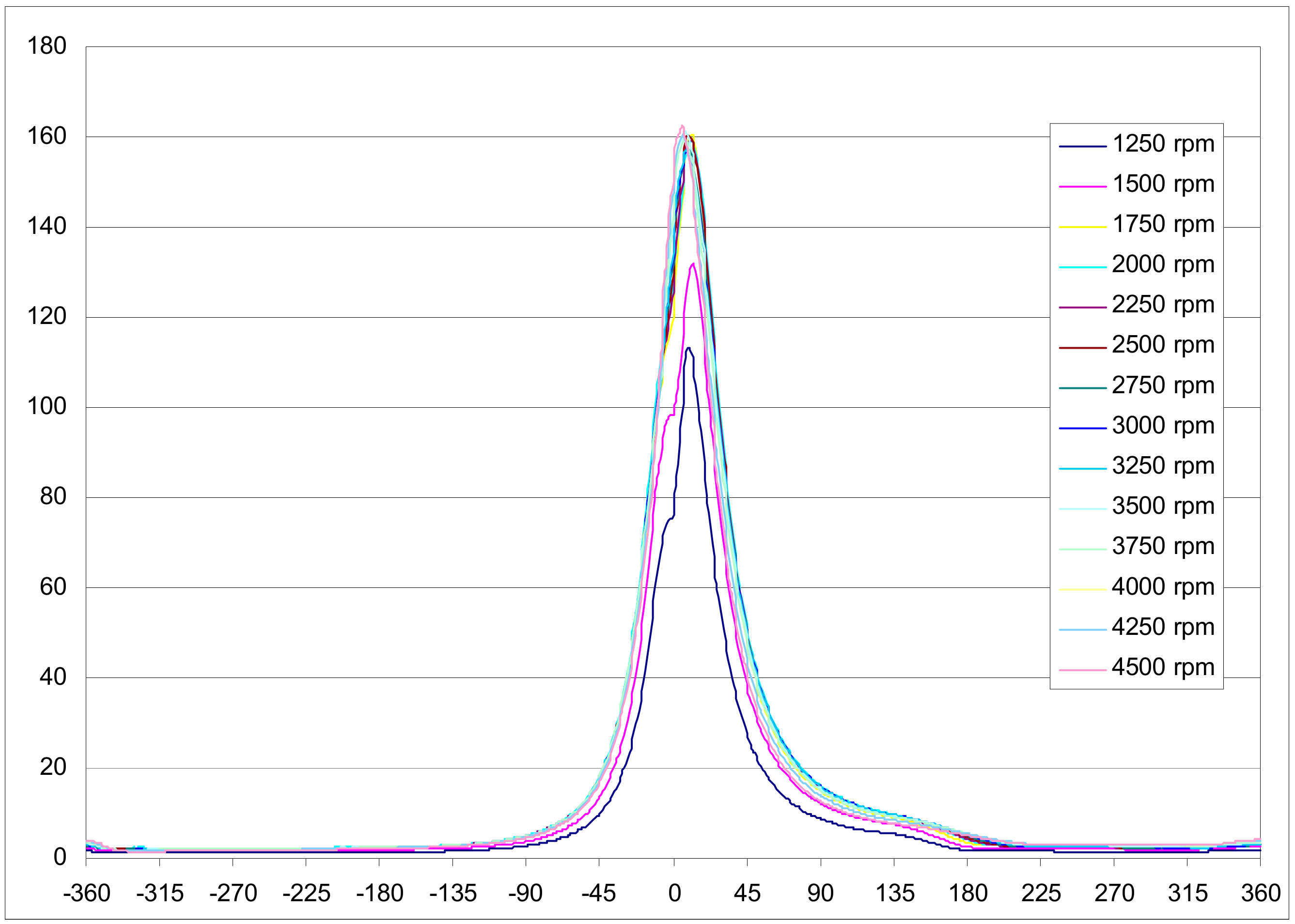
The applied external forces come from the pressure cycle of the combustion gases [25]: from Figure 1 it is possible to appreciate the cycle variations at different regimes. All the forces of an inertial nature are calculated internally by the code according to the actual speeds and accelerations of the bodies. Calculations performed for each operating regime and in the time domain provided the displacement, speed, and acceleration time histories of all the points of the system.
2.1. System Dynamic Reduction
The adopted flexible MB approach is ‘floating-frame-of-reference component-mode-synthesis (FFR-CMS)’, whose theoretical description can be found in the MB books by Shabana [26,27]. The Craig Bampton dynamic condensation [28] was adopted. The first 50 eigenforms are used for the modal reduction (such number is judged sufficient for the scope).
The free-free natural frequencies of the reduced model are calculated and provided as input to the MB analysis: when the flexible body is connected, through the various joints, to the other bodies included in the overall model, the constrained natural frequencies are calculated and used to solve the forced analysis by a modal response approach.
The concept underlying the creation of a MB model is to subdivide a mechanical system, having an overall nonlinear elastic behavior, into linear elastic sub-systems and to concentrate nonlinearities in the connections between them. The elastic bodies are represented by the condensed matrices of the corresponding FE model. A number of nodes, usually those chosen in condensation, having a mass and connected to each other by massless springs and dampers, discretizes each elastic body.
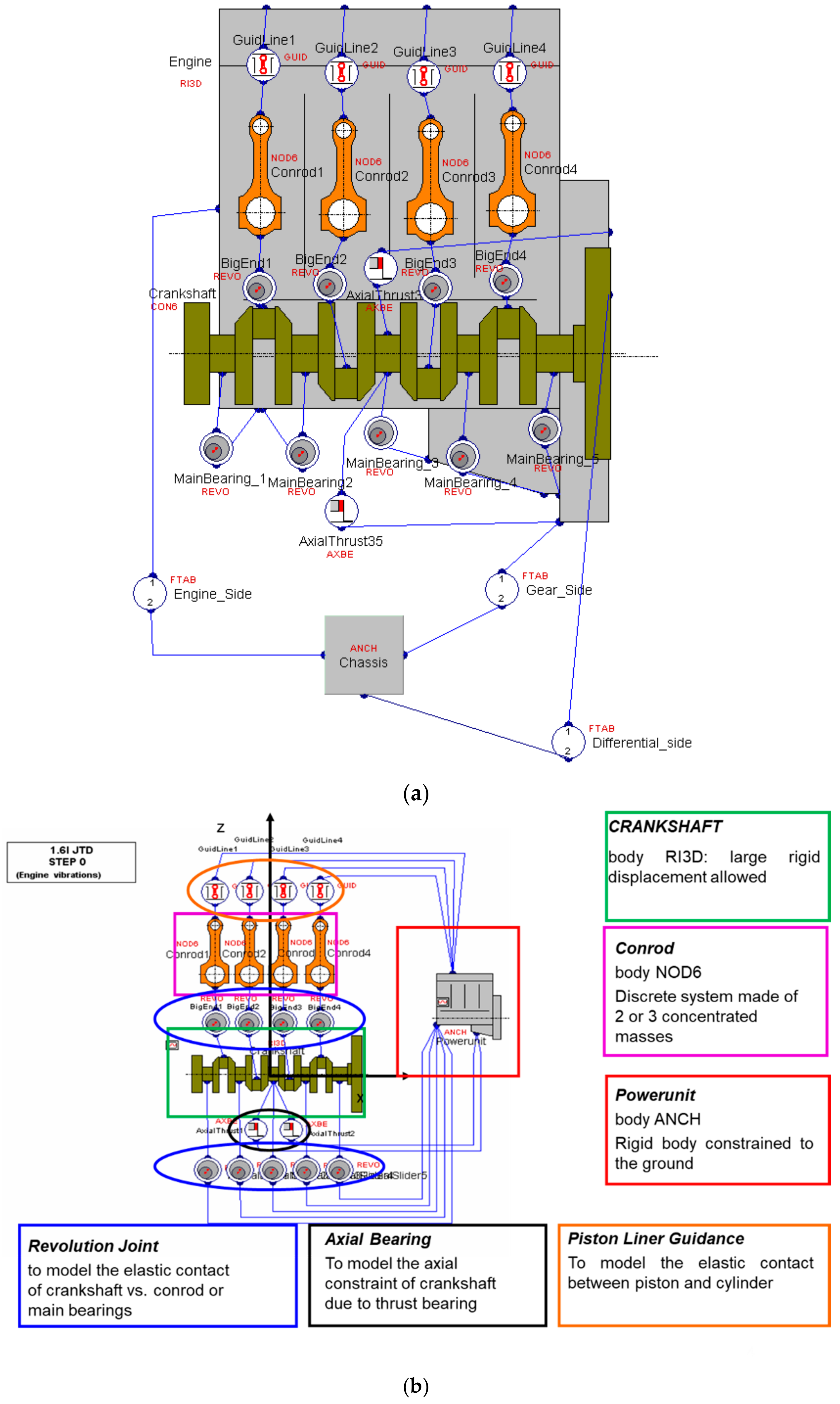
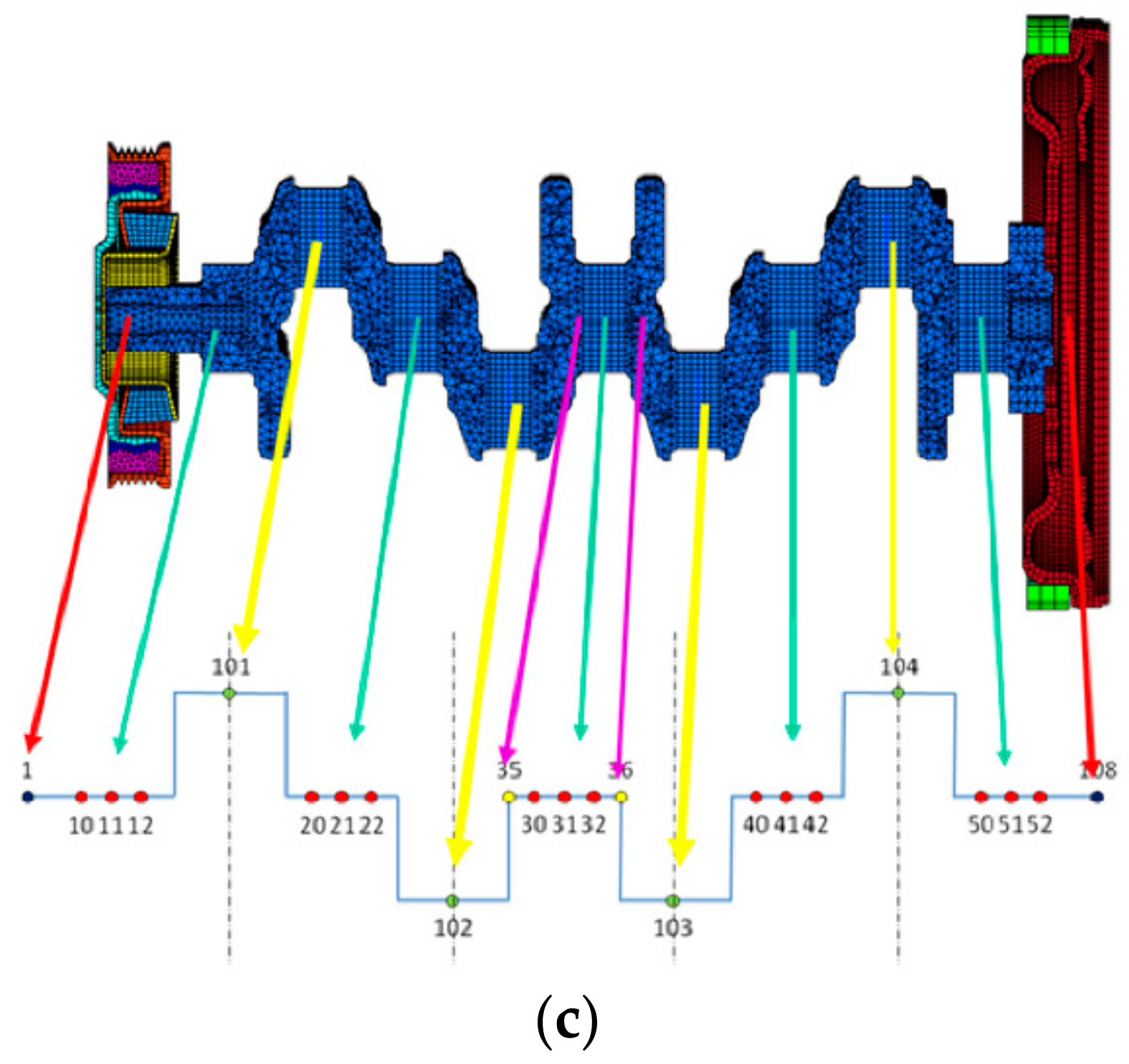
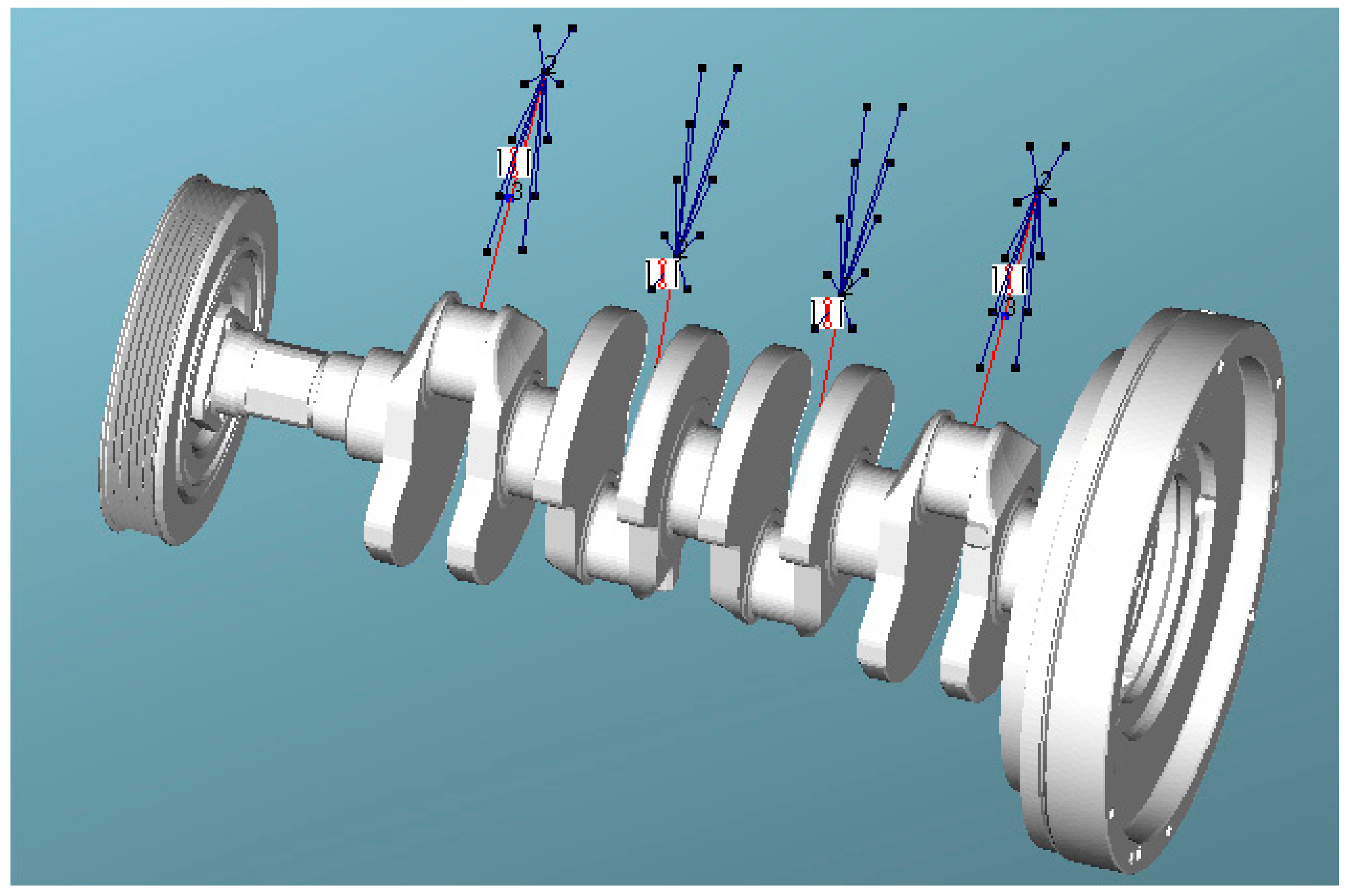
In Figure 2a,b the schematization of the constraints and components making up the engine are shown, with highlight of engine mounts (“FTAB” body) and corresponding location with respect to the engine (modeled as a rigid body “RI3D”). The condensation nodes of the flexible crankshaft (“CON6”) are shown in Figure 2c.
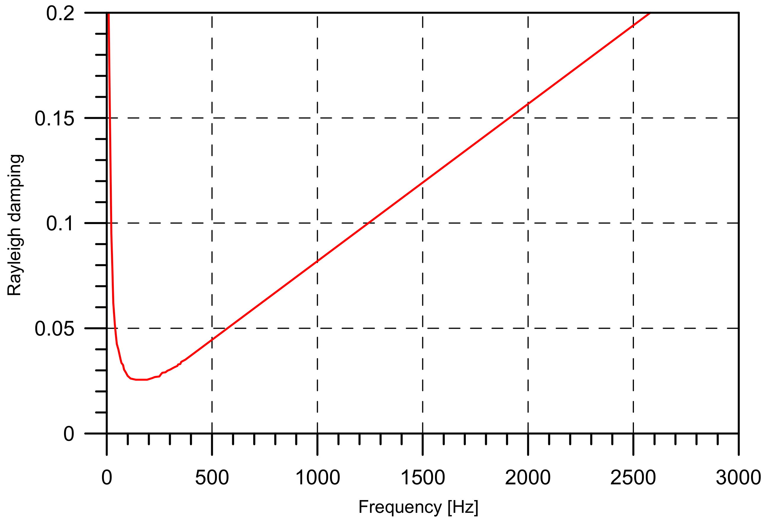
For the damping matrix, the MB software refers to the so-called ‘proportional damping’, known as “Rayleigh damping” (Figure 3). This can be defined by using two frequencies and the damping ratio at these frequencies. The function of the damping ratio ε is as follows:
where
ξi = (a + b ωi2)/(2 ωi) with ωi = 2 πfi,
- a and b are the calculated multiplication factors for the mass and stiffness matrix
- the recommended value for f1 is the first crankshaft eigenfrequency
- the recommended value for f2 is 1000 Hz
- the recommended value for d1 at frequency f1 is 0.03
- the recommended value for d2 at frequency f2 is 0.05
2.2. Models of Increasing Complexity
For the analysis of the vibration behavior of the internal combustion engine under examination, three models of increasing complexity were realized:
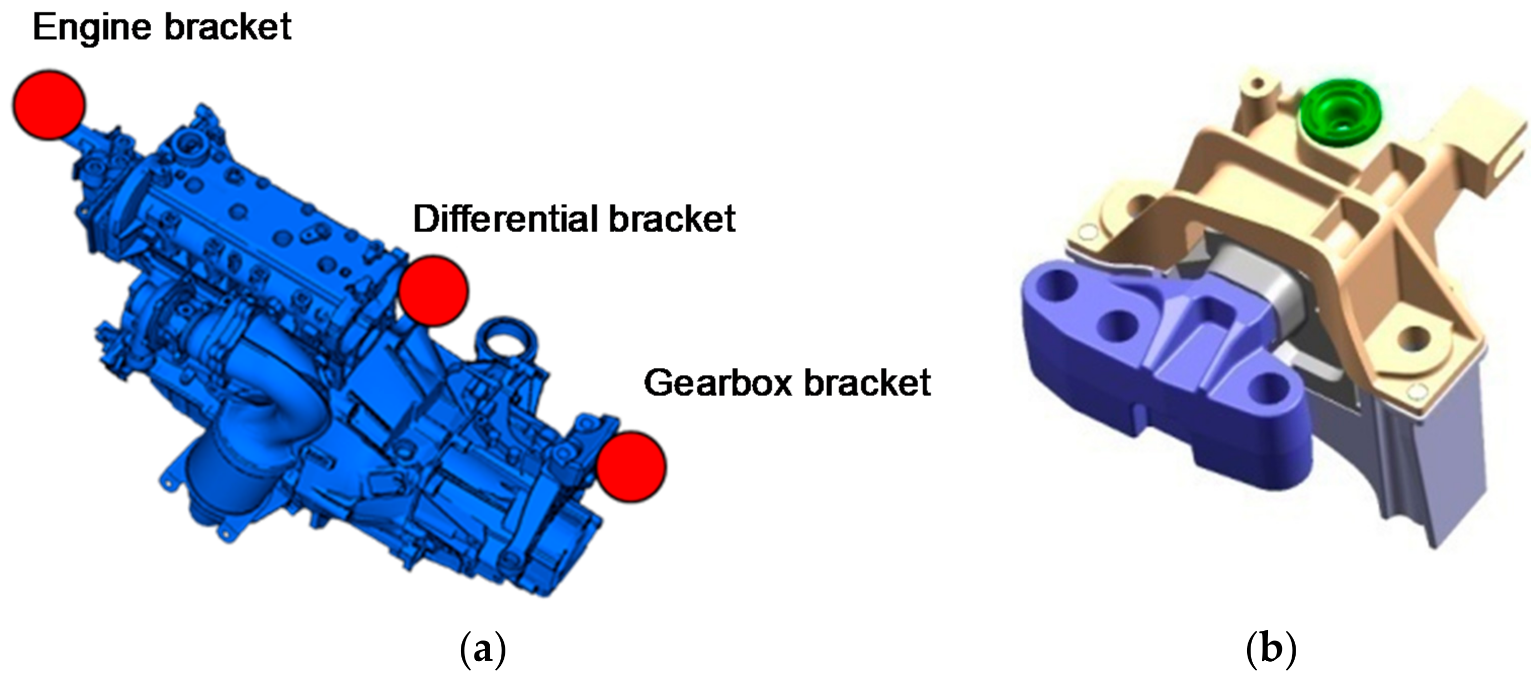
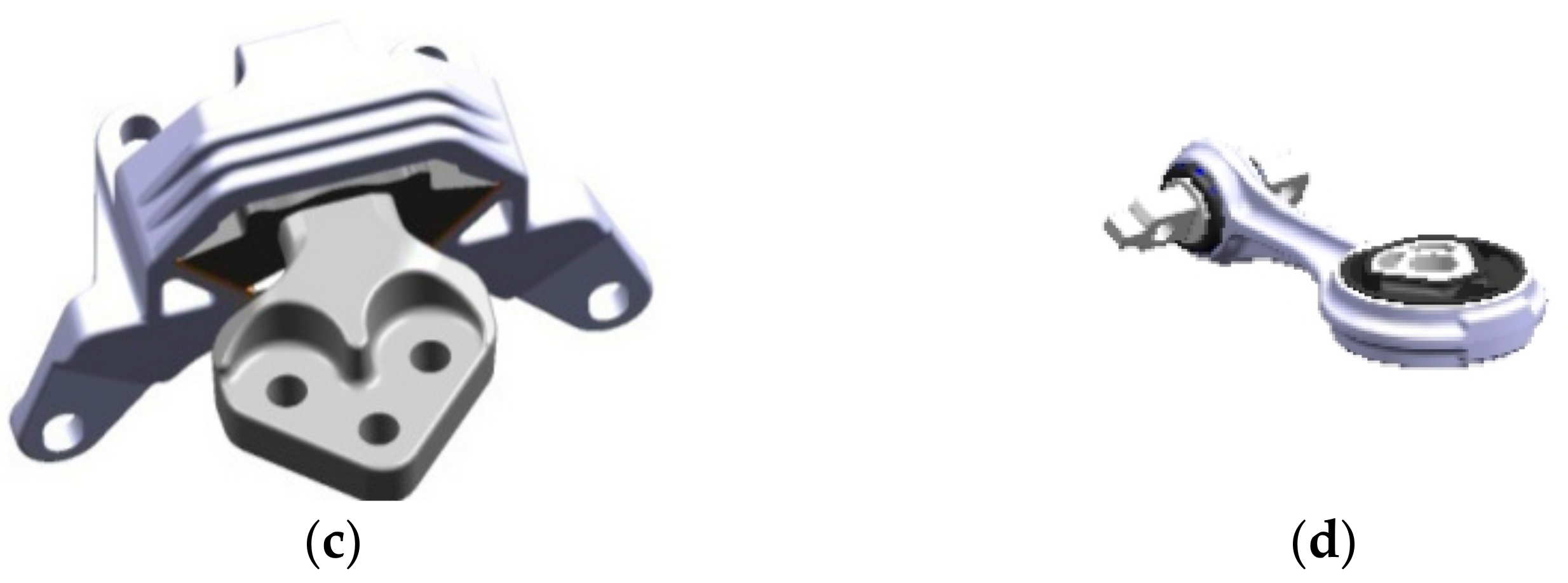
- The first approach, termed SOL1, realizes the simulation of the engine behavior using a rigid body model (Figure 4) and provides for the trend of the motion irregularities at low frequencies, with a first evaluation of the vibrations of the power train support brackets. The powertrain suspension brackets in the engine compartment are three: engine bracket, differential bracket, gearbox bracket (Figure 5a–d). These components are usually simulated in AVL/Excite as joints and treated as massless material points. The joints simulating the brackets were of Table Force/Moment type. This constraint allowed introducing the nonlinear behavior of the dowels stiffness’s; stiffness and damping values were assigned (retrieved from the car company database) in the three directions x, y, z for each bracket and for different relative displacement values. The stiffness and damping values for the power train mounts were provided by the supplier and consist in a nonlinear relation between stiffness/damping and mount deformation.
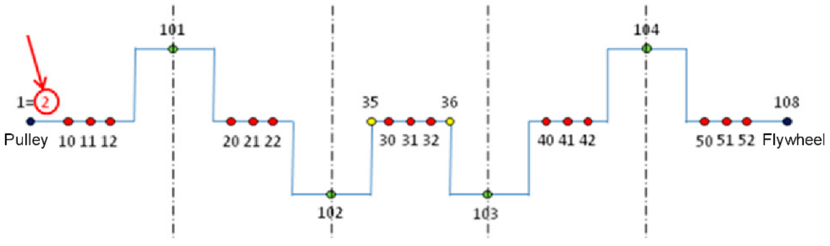
- The second model, termed SOL2, is based on FE modeling of the crankshaft, with pulley and flywheel, in order to consider the flexibility of the crankshaft that, once appropriately condensed, is introduced into the MB calculation code. The aim is to obtain the values of the motion irregularities in addition to the support brackets vibrations. Comparing Figure 6 and Figure 2b, it is possible to see an added condensation node (number 2) as requested by the splitting of pulley in two independent parts (capable of relative motion), the first (node number 1) referring to the shaft end and the second (node number 2) referring to the seismic mass. Now it is possible to point out the impact of torsional modes (in case they are excited) on the motion irregularities and support bracket vibrations. This will be analyzed in the next paragraph.
- The third model, termed SOL3, shows the FE modeling for both the previously considered crankshaft and the clutch unit.
For all the models, the remaining powertrain components were considered as rigid, with assigned characteristics such as weight, mass center position and inertia. The gearbox was not modeled, neither was present in the experimental bench test (an engine brake was adopted).
Therefore, the purpose of model SOL1 is purely methodological, while models SOL2 and SOL3 are those on which the analyses of interest and outcomes comparison were carried out.
2.2.1. Model SOL1
For model SOL1, some components were schematized by an appropriate rigid body, such as a crankshaft, pulley, flywheel, clutch, connecting rods, pistons, piston pins and rings, or power unit (base, head, oil pan, distribution components, and accessories). In these cases, the specifications of geometric characteristics, values of inertia, mass, and position of the centers of gravity were sufficient.
Moreover, the chassis was schematized by means of a “Generic Body” that represents the car chassis and can be considered as a constraint on the ground to which the powertrain must be clamped by three brackets: the engine, gearbox, and differential brackets (Figure 2a,b). In particular, “Generic Body” is a tool of EXCITE customized for the specific application by introducing the proper parameter settings.
In order to represent the constraints between adjacent bodies, appropriate joints were used (Figure 2a,b). In the case of bearings, they were modeled by a revolution joint, with a given spring stiffness (related to the bearing stiffness) and damping value (related to the oil film characteristics). The stiffness values of the bearings were available from AVL database and selected for this specific engine version based on the following default values:
- Stiffness at zero displacement 1e + 008 N/m
- Damping at zero displacement 10,000 Ns/m
- Stiffness at radial clearance 1e + 008 N/m
- Damping at radial clearance 20,000 Ns/m
- Radial clearance 0.0001 m.
The joint force in radial direction is determined in the plane perpendicular to the main rotational axis as a function of the previously described parameters.
The crankshaft was connected to the crankcase by means of “Revolute Joints” that simulate the presence of the main bearings; this type of constraint allows us to recreate a linear contact between the two bodies connected by a spring-damper modeling. In particular, the value of the clearance between shaft and crankcase and the stiffness and damping of the spring-damper system were inserted: these values depend on the maximum pressure in the combustion chamber, the bore, and the maximum force discharged on the single main bearings.
No modeling of the oil film was provided, namely, hydrodynamics of the fluid in the main bearings (e.g., between piston and cylinder liner and the connecting rod) was not considered. Actually, in the literature it is proposed to take into account even the elastohydrodynamic interactions for some applications, because, for vibroacoustic analysis, some local modes, like those in correspondence of the bearings, can play an important role especially when considering the crankshaft bending behavior. Anyway, the focus of this work was solely on the shaft torsional behavior. In fact, the elastohydrodynamic interactions generally do not influence the torsional behavior because, due to a sufficiently high crankshaft stiffness, there is no coupling between the bending modes affected by elastohydrodynamic interactions and the torsional modes. Moreover, elastohydrodynamic allowance would cause a huge increment (three times) of run times.
The bearings used in the engines to counteract the axial thrusts generated during motion were schematized with the constraint “Axial Thrust Bearing”; also for this case, clearance, stiffness, and damping values were provided. However, axial thrusts are considerably lower than those deriving from the vertical thrust, generated in the combustion chamber and acting on the main bearings (with this constraint, it was possible to connect a node of the shaft to more nodes of the crankcase).
The connecting rods were connected to the power unit through two constraints: the first component was a prismatic guide schematized through the Piston-Liner Guidance constraint and used to simulate the constraint between rods and plungers; the second component simulated the connecting rod bearing, for which the joint used for main bearings was taken into consideration.
The presented modeling does not calculate the torsional critical speeds, since the motion of this calculation model is rigid, and therefore it is a zero-pulse model. Therefore, the elements making up the system do not deform and rotate at the same speed.
2.2.2. Model SOL2
Model SOL2 introduces the flexibility of the crankshaft, getting a different dynamic behavior of the system and allowing the evaluation of those critical torsional speeds non-visible from model SOL1. This element of flexibility was introduced into the analysis through an FE modeling of the body crankshaft. The crankshaft comprised 150,000 nodes, 6 degrees of freedom (DOFs) per node, whereas the reduced condensed model comprised 50 nodes and 300 DOFs.
The free-free natural frequencies of the reduced model were calculated and provided as input for the MB analysis. When the flexible body was connected through the various joints to the other bodies included in the model, the constrained natural frequencies were calculated and used to solve the modal frequency response analysis.
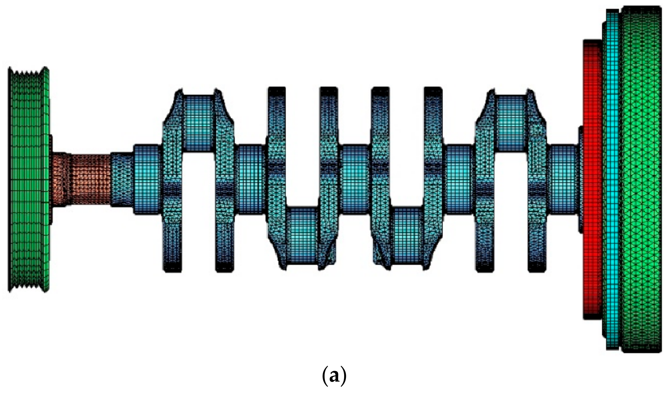
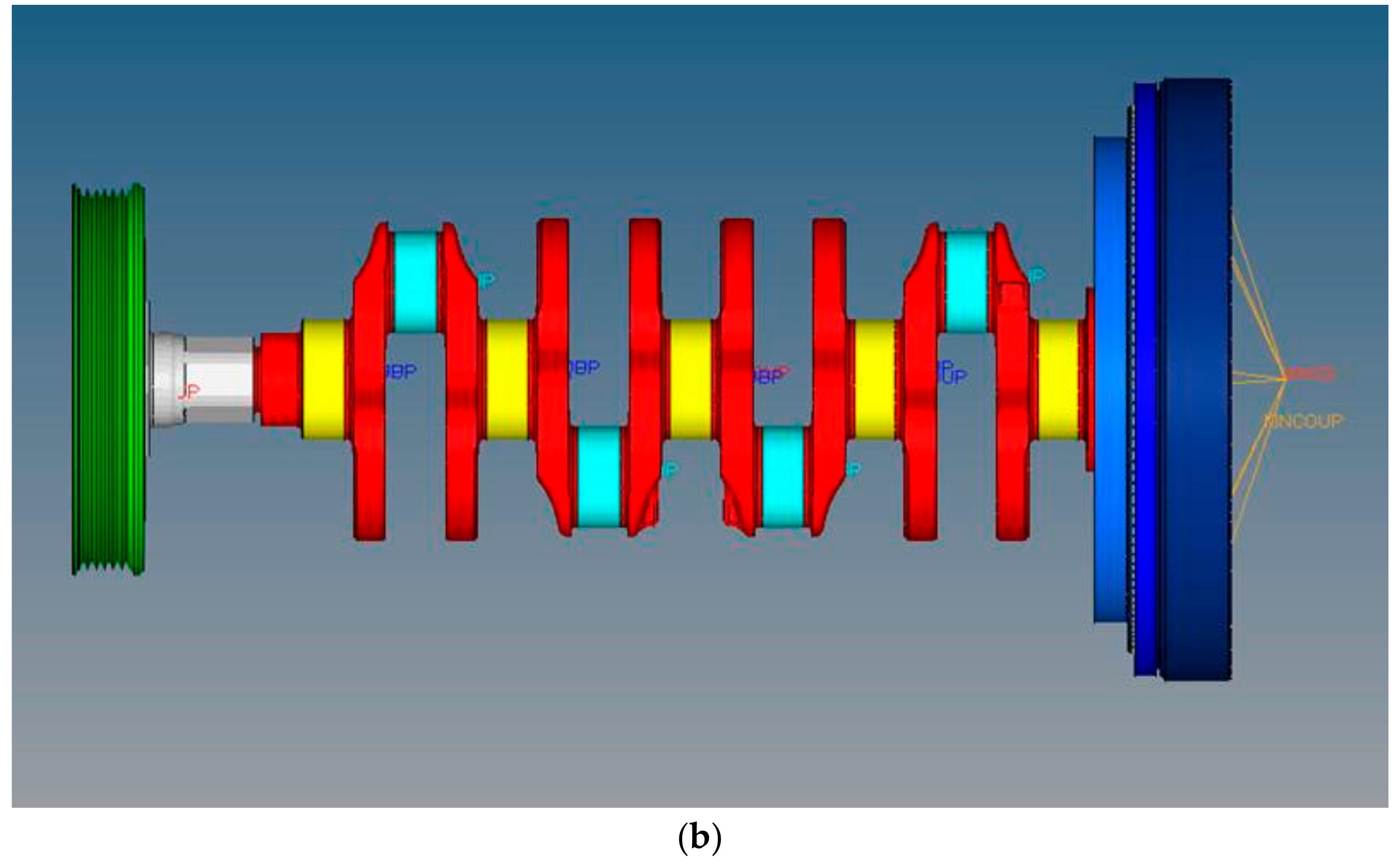
In such a model (Figure 7), the clutch unit was modeled as a concentrated mass. Figure 8 shows the FE models of the flywheel and pulley.
The adopted mesh utilizes tetrahedral elements with an average size equal to 0.5 mm.
2.2.3. Model SOL3
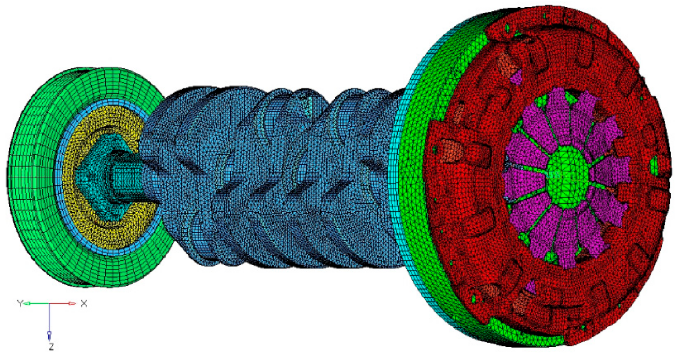
Model SOL3 comprises the FE modeling of the clutch mechanism (Figure 9) in addition to the crankshaft already present in the SOL2 model.
Crankshaft and clutch mechanism meshes comprised nearly 450,000 tetrahedral and hexahedral elements and nearly 140,000 nodes. The salient features of the three models, SOL1, SOL2 and SOL3, are also condensed in Table 1.
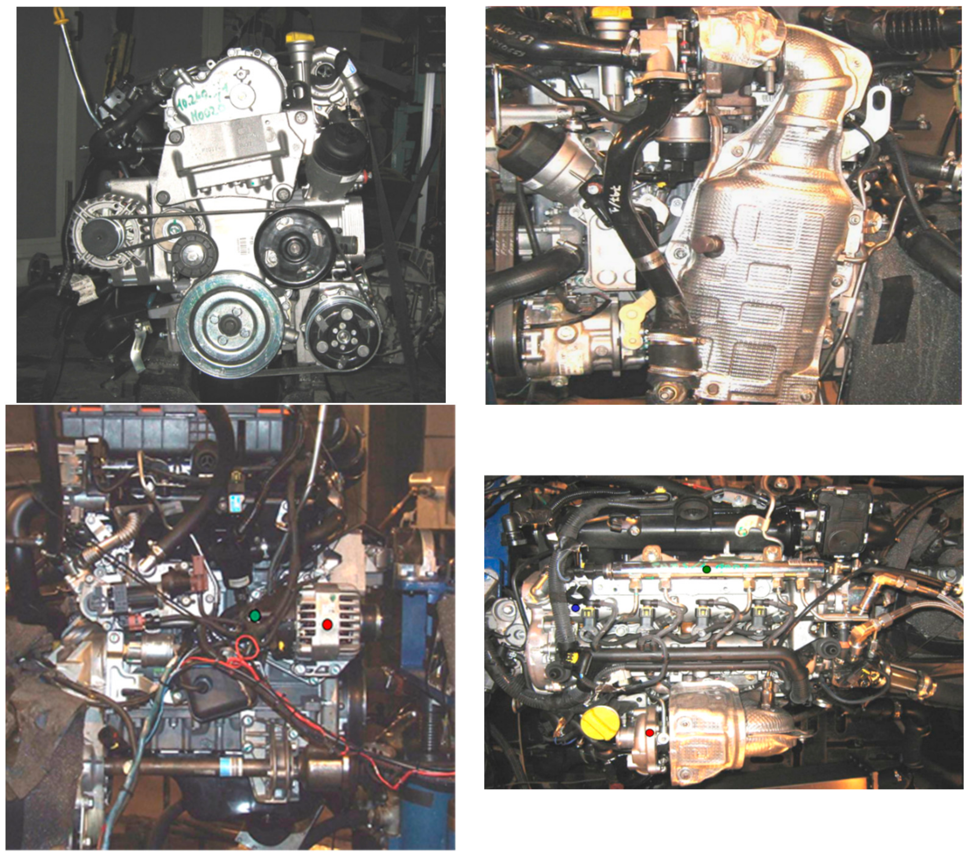
2.3. Experimental Setup
The experimental measurements were performed on a test bench (Figure 10), considering in particular a measurement point located on the powertrain flywheel. Therefore, in order to have a reliable comparison, the experimental motion irregularities were compared with the numerical ones in a reference node located in the mass center of the flywheel (node 108 shown in Figure 6). Calibration between numerical and experimental tests was based on the measured torque.
A preliminary check on the correlation of free-free numerical and experimental crankshaft eigenmodes was performed with satisfactory outcomes.
3. Results
3.1. Model SOL1
Although not leading to useful outcomes regarding the determination of the critical torsional speeds, Model SOL1 allowed us to obtain important outcomes for the model verification purposes, i.e., motion irregularity of crankshaft and global vibration index for the brackets.
It is well known that in an internal combustion engine, the engine torque generated by gas and inertia forces is periodic and subject to breakdown into a Fourier series as a sum of harmonics that can be more or less relevant to the engine dynamics according to the associated amplitude, phase, and order value.
3.1.1. Motion Irregularities
The outcomes of the simulation obtained with a rigid crankshaft (SOL1), focus on the study of the motion irregularities detected in the center of gravity of flywheel (node 108), hub (node 1), and seismic mass (node 2), as in Figure 6.
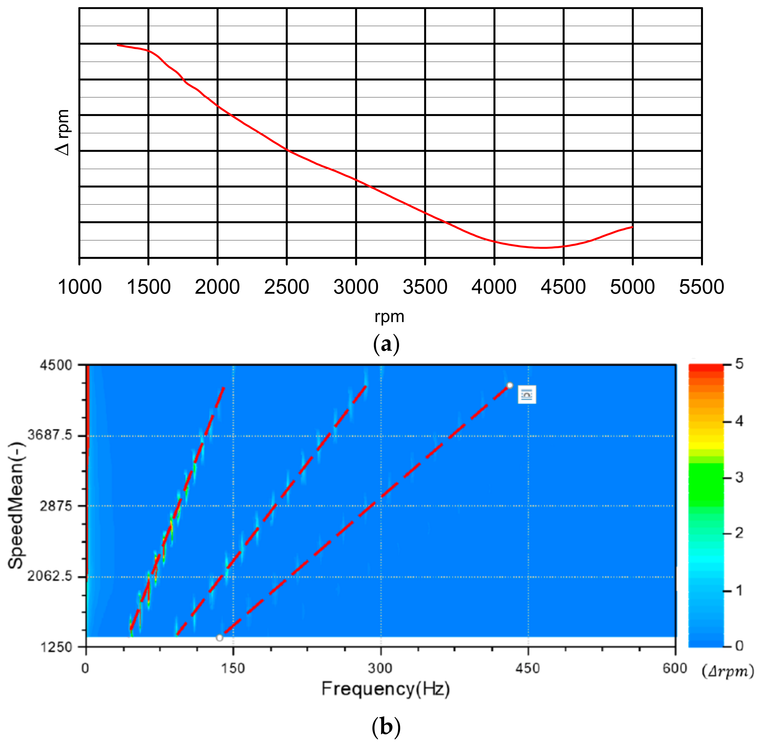
The even orders are the most relevant for the engine torque of a 4-stroke, 4-cylinder engine; therefore, their influence should be considered for motion irregularities assessment. Consequently, an evaluation of the magnitude of the 2nd engine order of crankshaft motion irregularity vs. speed was primarily carried out for the engine under test (Figure 11a).
The Campbell diagram represents the frequency spectrum of a non-stationary signal, in which the frequency is on the abscissa and the average angular velocity is on the ordinate, whereas the plotted data indicate the oscillation amplitude of the variable under test (in this case Δrpm). Campbell diagram for the motion irregularity evaluated on the flywheel (Figure 11b) clearly shows the prevalence of the 2nd engine order. It is interesting to observe that the 6th order seems to play a negligible role in the motion irregularities; however, this will be invalidated when the allowance for modal behavior is included in the analysis, triggering resonance with a torsional mode.
3.1.2. Global Vibration Index
A global vibration index, named as weighted sum, was also calculated for the brackets and defined as follows:
where:
- wi(f) is the weighting factor for a given direction and position,
- xi(f) is the rms acceleration for a given direction and position,
- n is the total number of positions and directions (x, y and z) = number of brackets × 3.
The weighting factors used in Equation (1) depend on the vehicle in which the powertrain has to be installed and are generally provided by the vehicle platform unit. Without such information, as in the present case, the coefficients are all set to 1 (uniform weighing of the structural transmission paths).
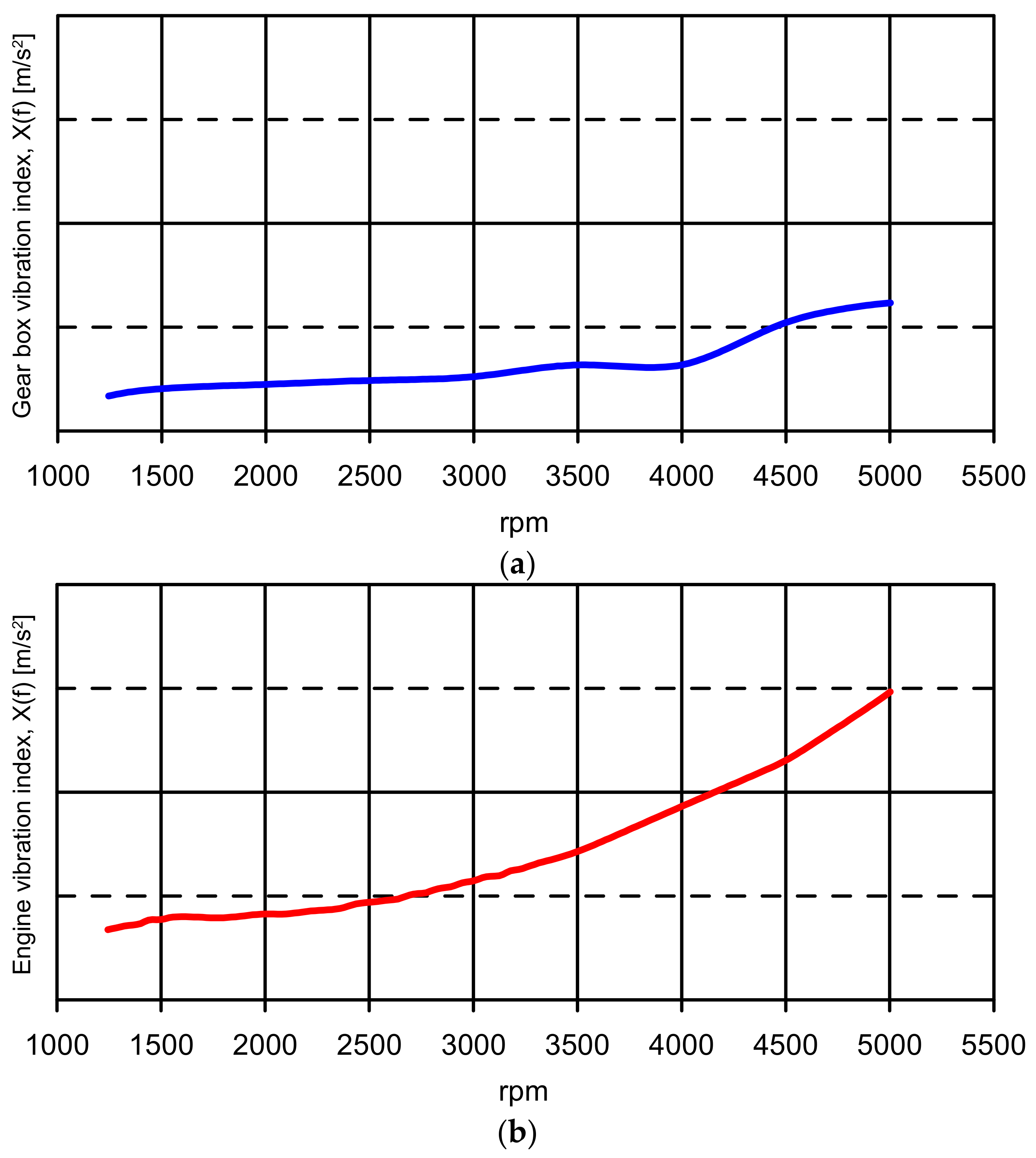
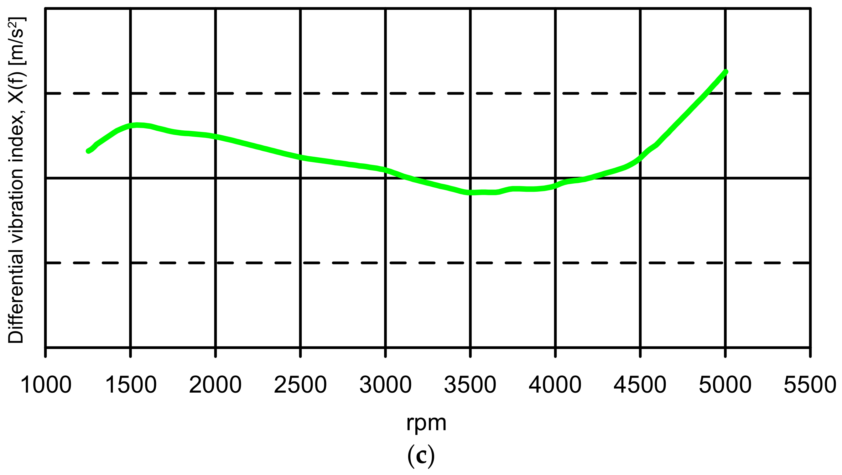
The second order of the global vibration index of each bracket (engine, gearbox and differential brackets) is shown in Figure 12, with a contribution that is nearly frequency independent for gearbox and differential brackets, but increasing with frequency when considering the engine bracket. The corresponding global vibration index is shown in Figure 13 with reference to the amplitudes of numerical and experimental acceleration irregularities, and therefore to the amount of the transmitted vibration. Such a good numerical–experimental agreement can be explained by observing that the 2° engine order cannot trigger a torsional mode and consequently, when considering the second order effect, there is no loss of accuracy by neglecting the crankshaft flexibility.
Model SOL1 allowed us to verify some operating parameters, such as the motion irregularities and the global vibration index for the brackets; it also allowed us to highlight that, as expected, the second engine order harmonic force is predominant when neglecting the flexibility of any component.
3.2. Model SOL2
3.2.1. Motion Irregularities
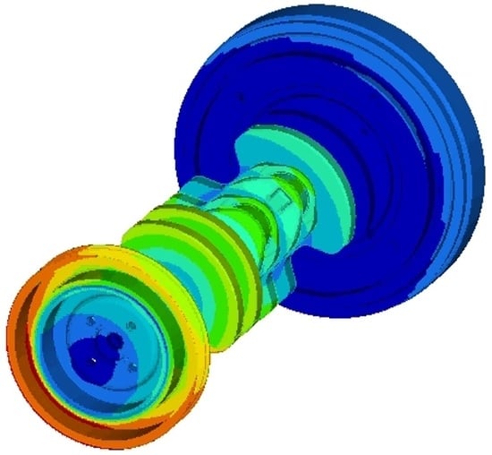
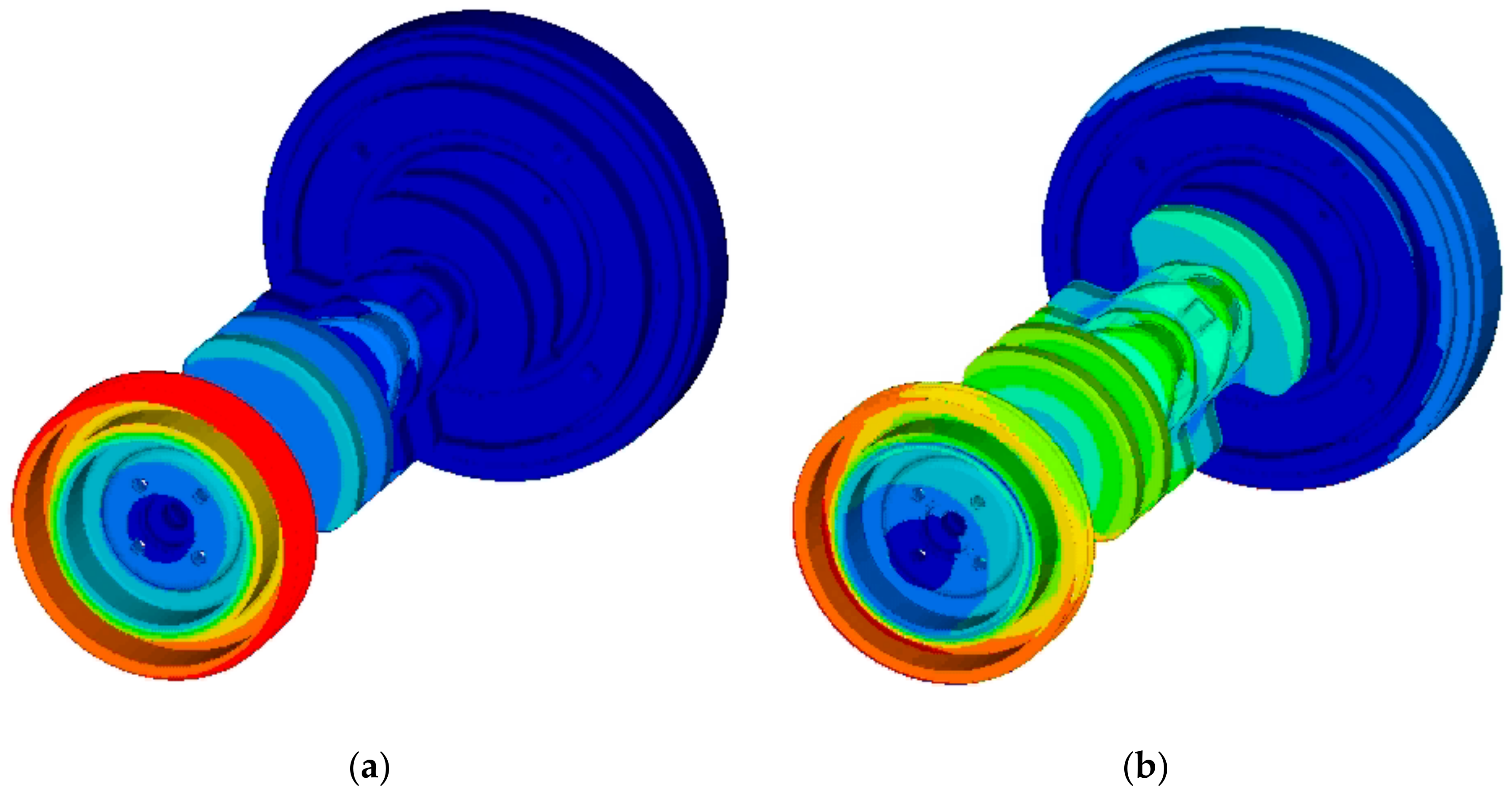
From the modal analysis, it is possible to observe that, for the engine under testing in its operating frequency range, considering the real constraints (as enabled by the multibody analysis), the first two torsional modes are at 305 and 545 Hz, respectively (Figure 14). In the former, the hub and the seismic mass oscillate in phase, whereas their oscillation is out of phase for the latter. Anyway, the differences between free-free and constrained torsional eigenfrequencies are very low (nearly 15 Hz considering the first torsional mode with vertical and transversal springs at the bearings’ locations); on the contrary, a relevant difference exists between the free-free and constrained bending modes.
The primary objective here is to detect how the amplitude of the motion irregularities is affected by the shaft torsional eigenfrequencies: in fact, in correspondence of resonances, the irregularities may have values so high as to make them critical to the vibroacoustic behavior of the whole powertrain.
The outcomes of model SOL2 are compared with the test data to assess the accuracy of this modeling. Considering that the experimental measurements are only available on the flywheel center, the numerical–experimental comparison can only involve node 108 (Figure 6).
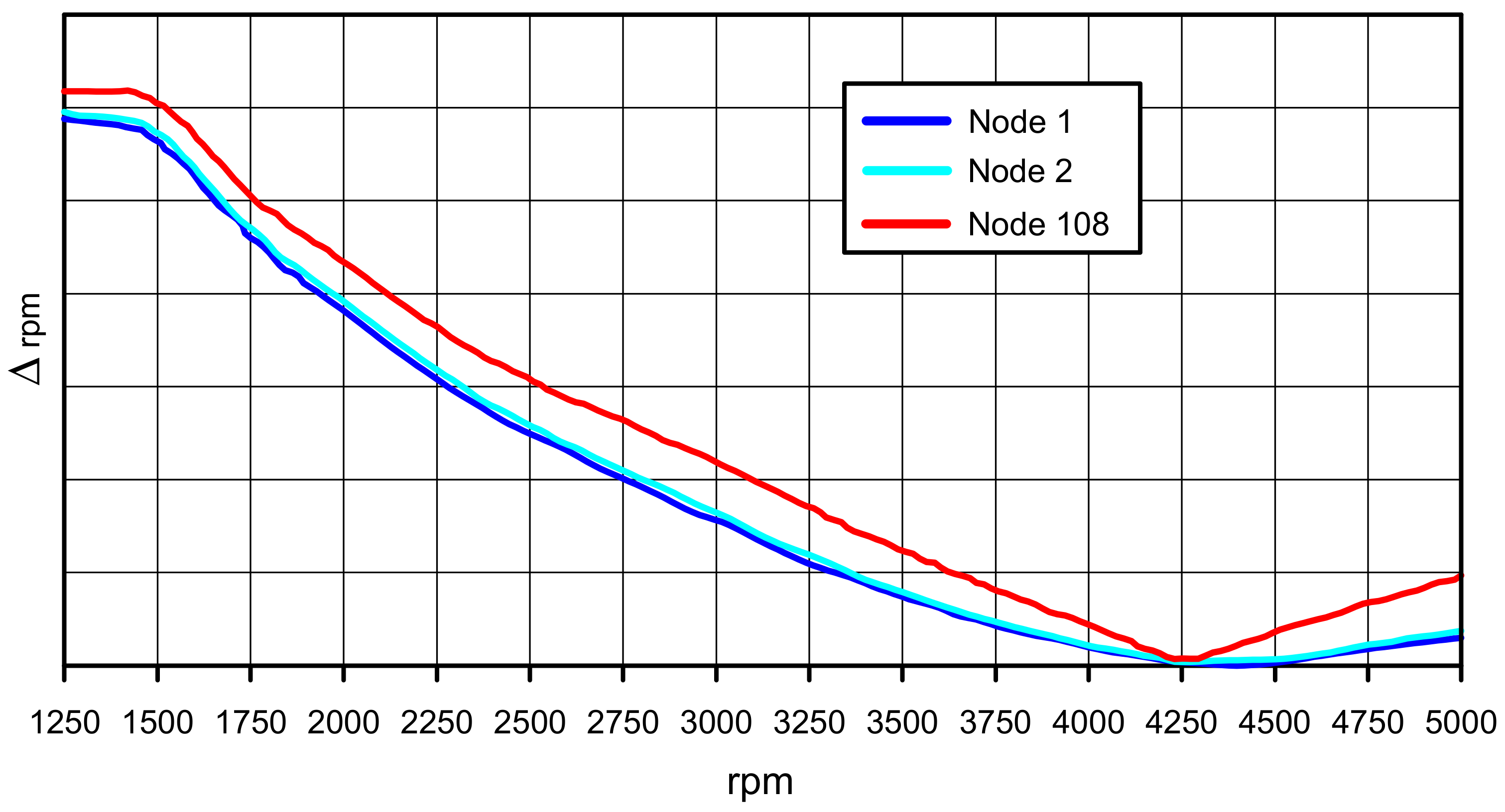
The 2nd order of motion irregularity does not display any peak in the range 1250–5000 rpm (Figure 15); this is expected since the maximum involved excitation frequency,
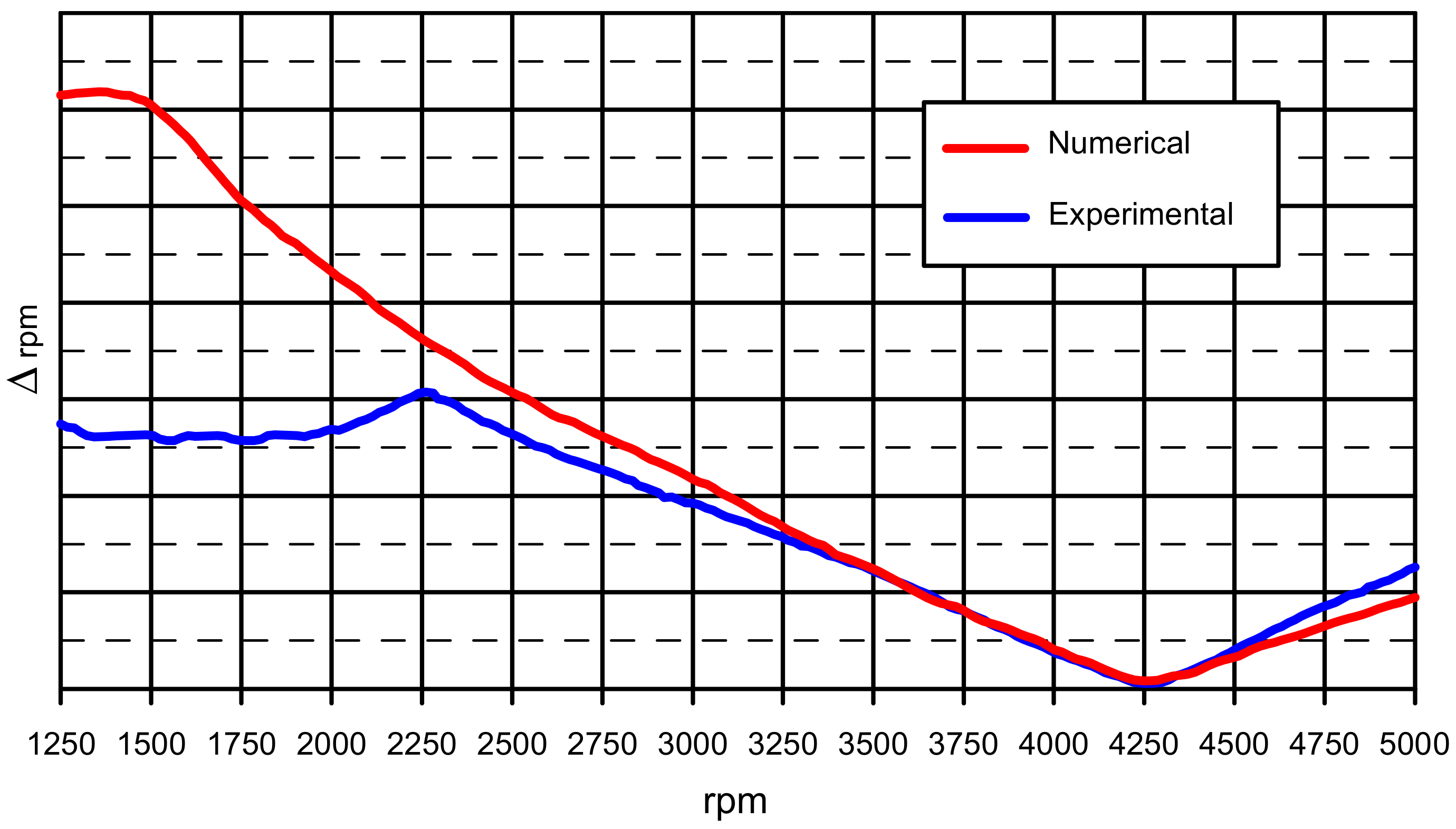
is not sufficiently high to trigger the first torsional eigenmode at 305 Hz; consequently, SOL2 provided the same results of SOL1 and a satisfactory correlation with experimental measurements made at flywheel (node 108), as in Figure 16. The minimum of the motion irregularities is at nearly 4250 rpm: in correspondence with such a regime, the combustion forces and inertia forces are almost in equilibrium.
f = 2 × 5000/60 = 166.7 Hz,
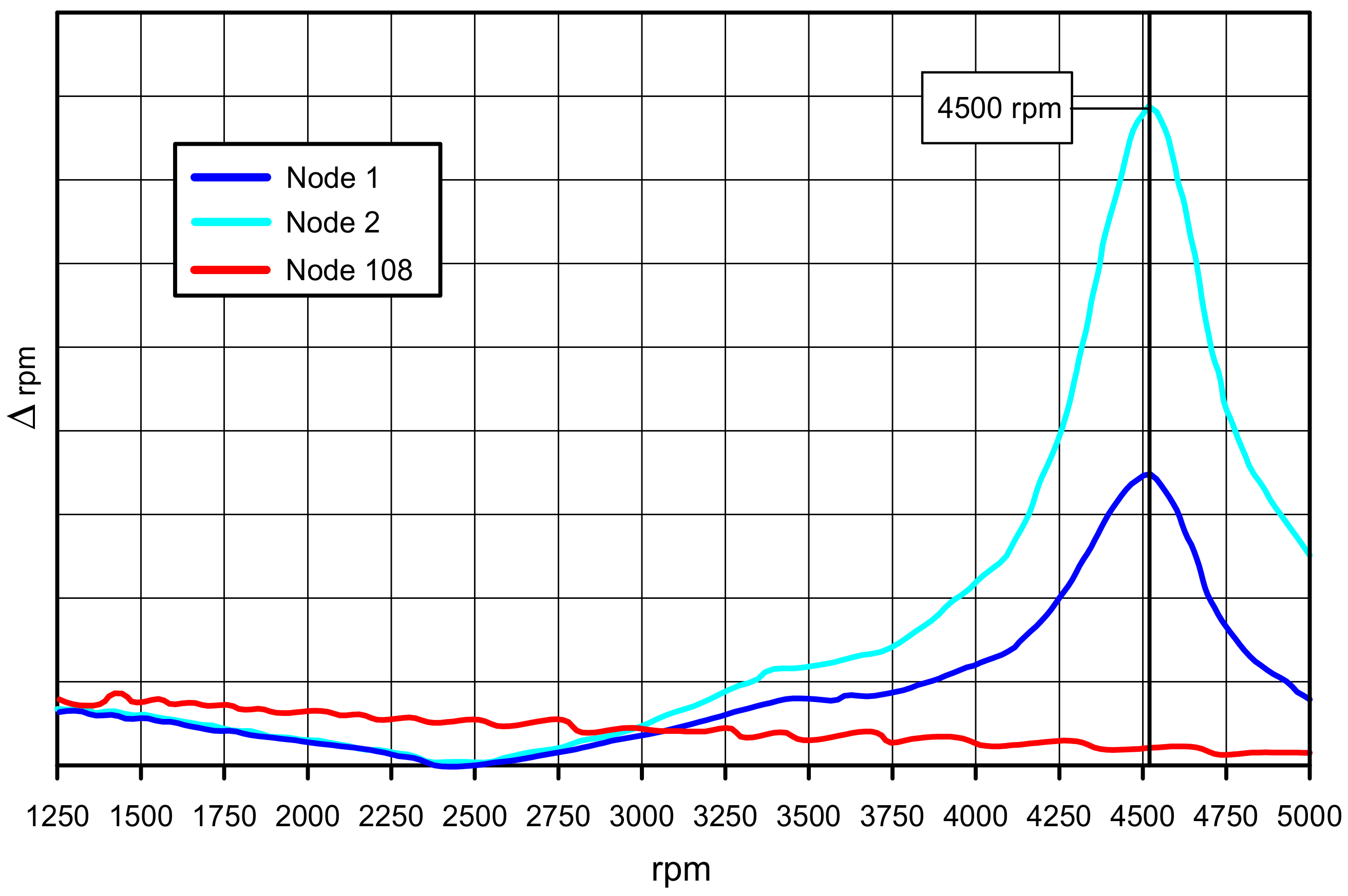
On the contrary, the 4th order of motion irregularity does display a peak in the range 1250–5000 rpm at nearly 4500 rpm (Figure 16), corresponding with the frequency
which is sufficiently close to the 1st torsional eigenfrequency (305 Hz) to confirm the hypothesis of a resonant behavior for the crankshaft. Such a peak only manifests with reference to nodes 1 and 2, but is negligible for node 108 (Figure 17).
f = 4 × 4500/60 = 300 Hz,
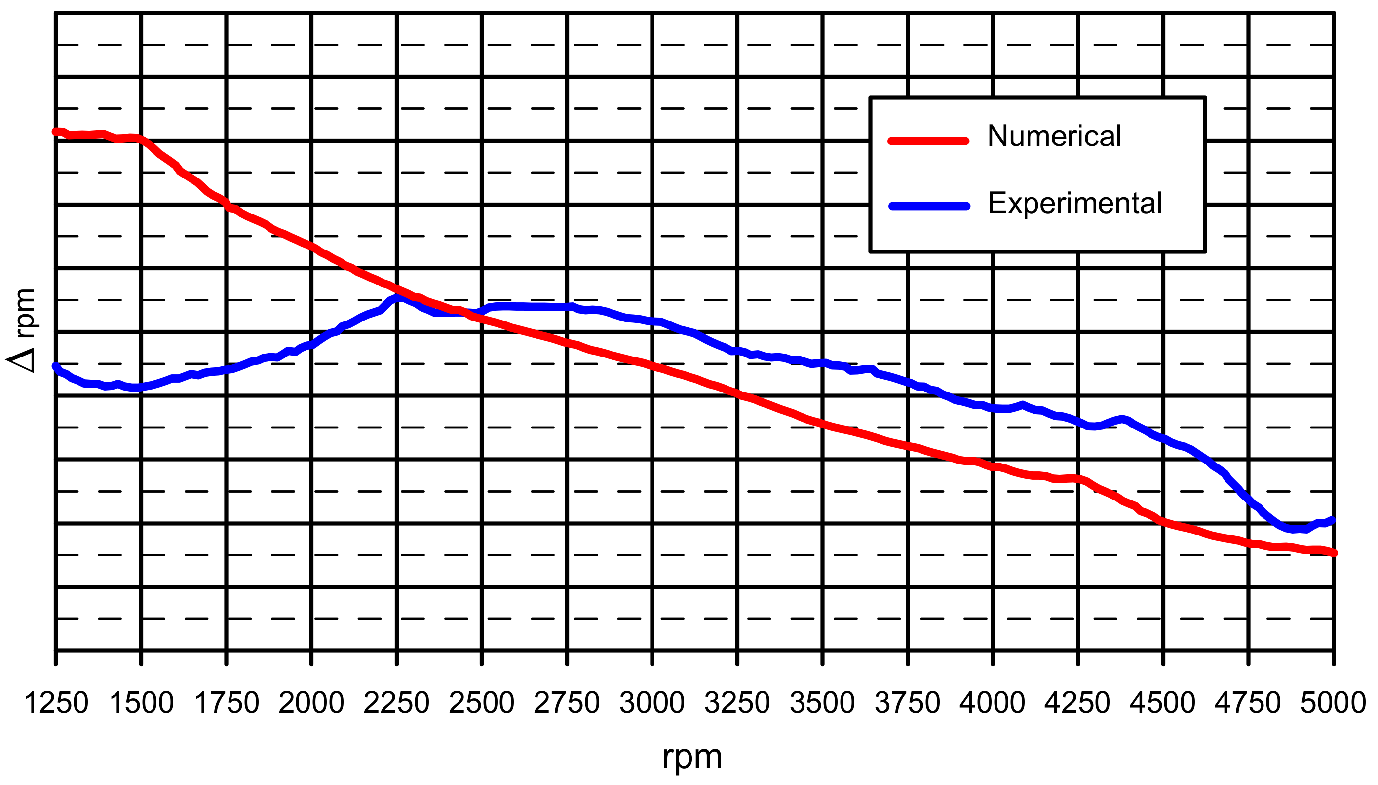
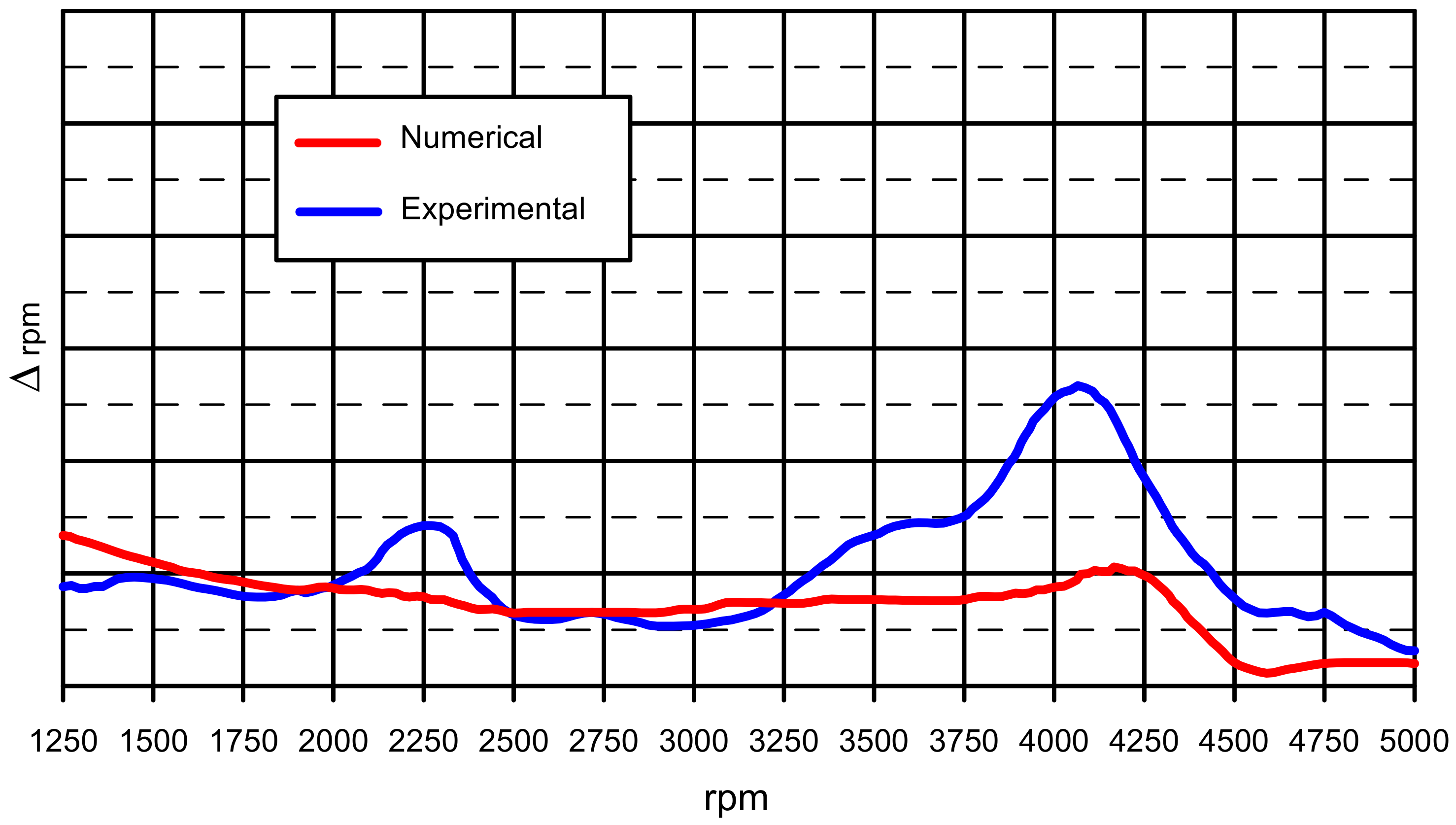
A good correspondence between the numerical and experimental results is provided by SOL2 (Figure 18) for regimes higher than 2000 rpm, even if a slight underestimation of the irregularities is obtained. The lack of numerical vs. experimental correlation at low regimes is expected due to the turbolag phenomenon. In fact, during the bench test based on an acceleration from the min to the max regime, the turbo did not properly work at low regime (lower than 2000 rpm), whereas the simulation cannot allow for such behavior since it is based on a quasi-stationary variation of loading conditions.
It is worth noting that, as expected, the amplitude of oscillation for node 2 is higher than that of node 1: in fact, hub and seismic mass oscillate in phase, with the latter being more peripheral and consequently having larger oscillations.
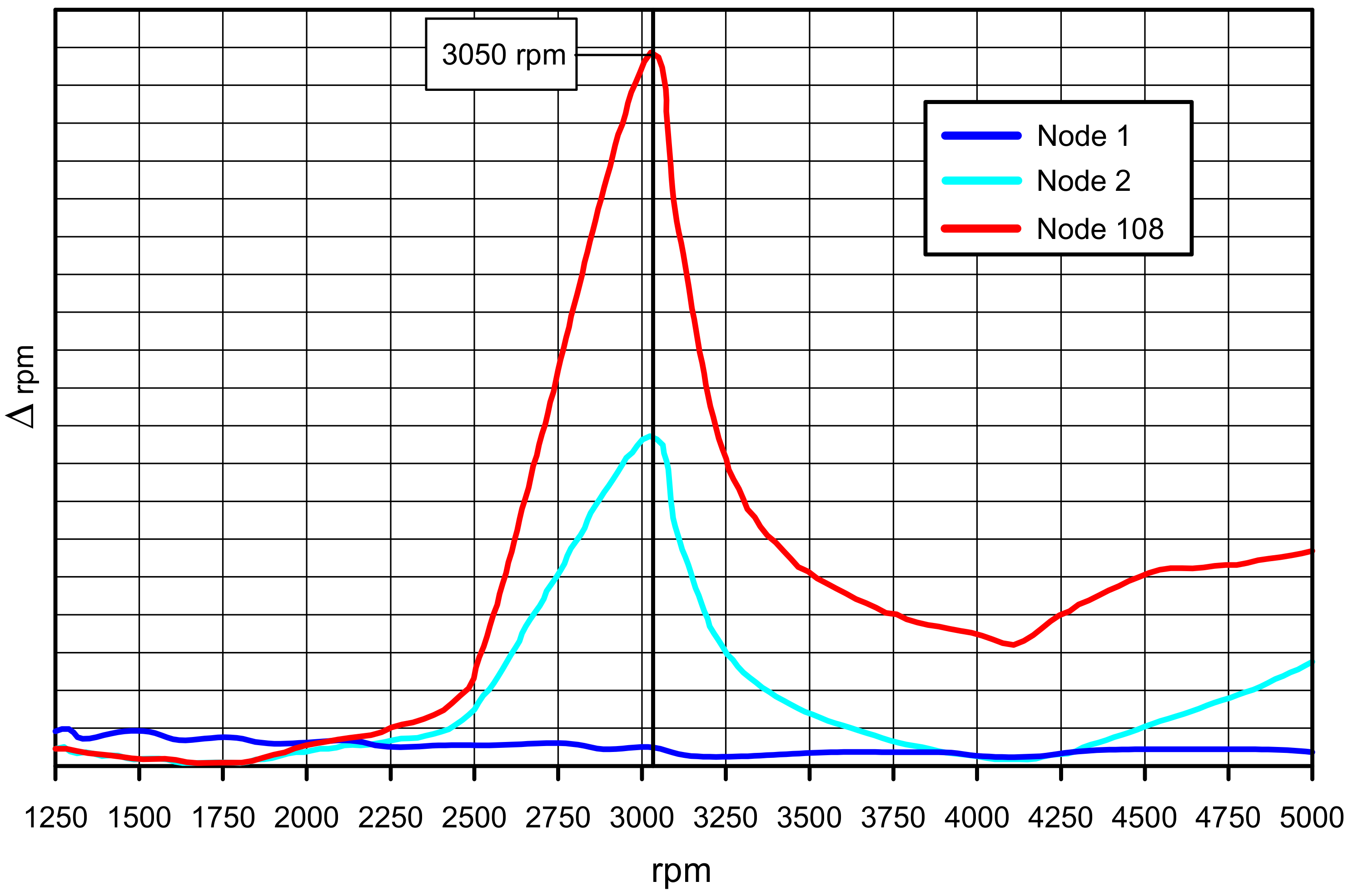
Exploring the 6th order, a numerical peak at nearly 3050 rpm can be observed [18], corresponding with the frequency
which, again, is coincident with the 1st torsional eigenfrequency (305 Hz), confirming the hypothesis of resonant behavior for the crankshaft.
f = 6 × 3050/60 = 305 Hz,
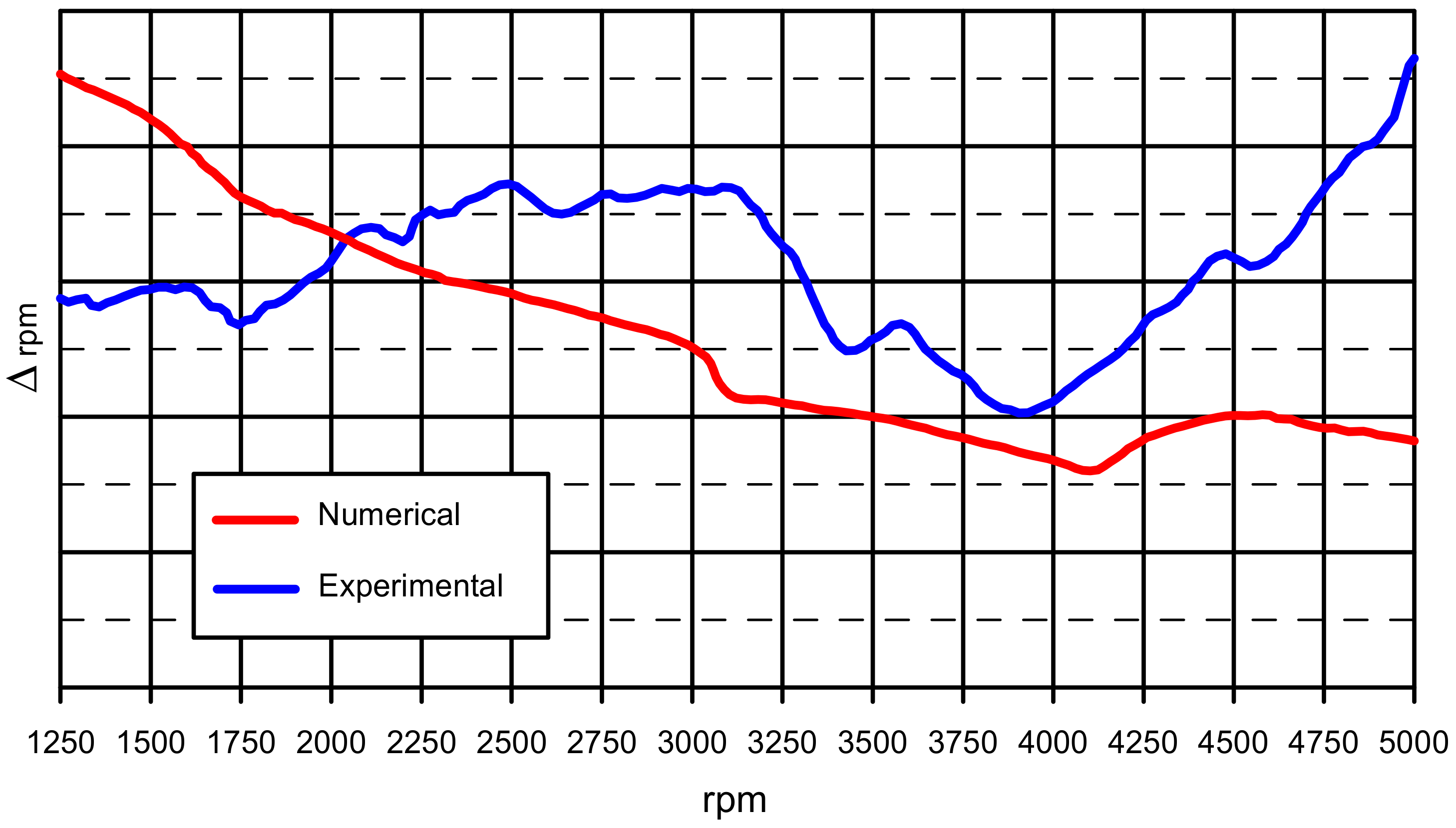
The experimental peak is at 3100 rpm, whereas the numerical peak is at 3050 rpm (Figure 19): this discrepancy can be attributed to the “discrete” acquisition procedure adopted in the test.
The discrepancies of motion irregularities at the low regimes can be surely explained by the turbolag phenomena, whereas the non-negligible underestimation provided by the simulation at high regimes (Figure 20) might be caused by the fact that the only crankshaft is modeled as flexible.
Regarding the 8th order, two peaks at nearly 2250 and 4250 rpm can be found (Figure 21), corresponding with the frequencies
f1 = 8 × 2250/60 = 300 Hz,
f2 = 8 × 4250/60 = 567 Hz.
These frequencies are sufficiently close to the 1st (305 Hz) and 2nd (545 Hz) torsional eigenfrequencies, confirming the hypothesis of resonant behavior for the crankshaft.
Again, a slight underestimation of motion irregularities provided by the simulation is evident (Figure 22).
In conclusion, the 2nd torsional eigenfrequency cannot be triggered by orders lower than the 8th; moreover, orders higher than the 8th are neglected because their amplitude is sufficiently low to prevent a relevant impact when triggering the torsional eigenfrequencies.
3.3. Model SOL3
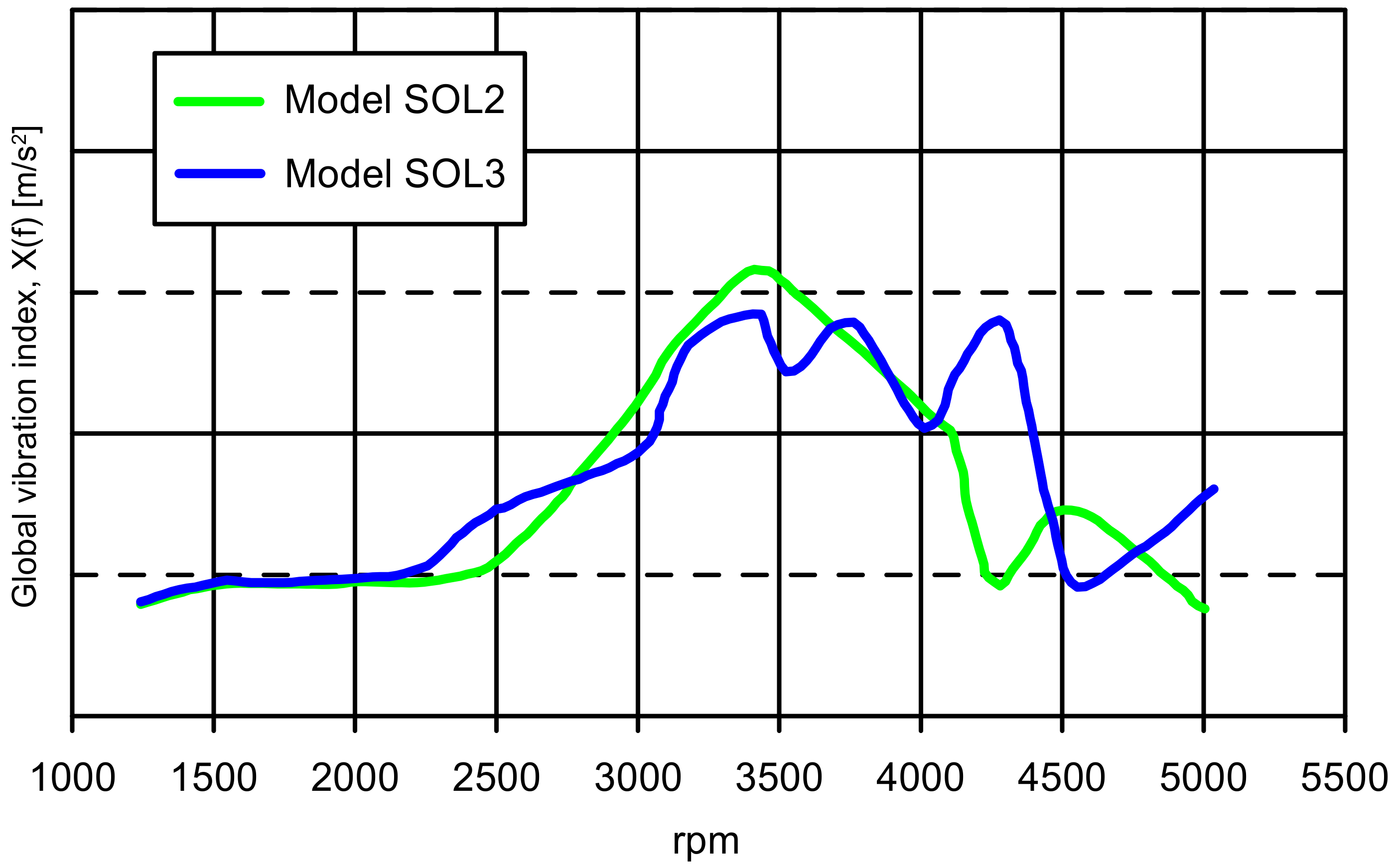
Regarding model SOL3, the outcomes of the 2nd engine orders motion irregularities do not significantly differ from those observed for model SOL2. In contrast, different results between the two models are obtained for the 4th engine order (Figure 23). In particular, a different trend of the brackets vibrations due to the explicit FE modeling of the clutch mechanism is observed.
4. Conclusions
In this work, three internal combustion turbocharged diesel engine multibody models of increasing complexity were developed and their vibration behavior observed.
The development of these multibody models allowed us to analyze the support brackets vibrations and crankshaft motion irregularities in order to proceed to a design optimization solution in production and/or the development phase.
The choice of adding the only flexibility of crankshaft, flywheel, and pulley is related to the range of frequencies of interest (up to 650 Hz) and to the exclusive focus on the impact of the crankshaft torsional behavior (the flexibility of other powertrain components comes out at higher frequencies). Consequently, in the frequency range of interest, it was not necessary to adopt complex models for the calculation of both the vibrational index at the engine brackets and the irregularity motion of crankshaft, with a substantial reduction in the computational burden.
The obtained outcomes of the three analyzed models can be summarized as follows:
- for what concerns the 2nd engine order motion irregularities and global vibration index, the rigid body model showed a good correlation with the experimental outcomes;
- the model with just the flexible shaft showed an adequate degree of correlation for the 2nd and 4th engine order motion irregularities; such a model represented the best compromise between the required computational effort and expected accuracy, also providing results that can be used for analyses requiring more in-depth study;
- the addition of explicit FE modeling for the clutch mechanism allowed us to improve the accuracy for the 4th engine order support brackets’ vibrations.
The next steps for this work would be allowance for the flexibility of engine block and engine subsystems in order to calculate the impact of its resonances on the monitored vibrational parameters at higher frequencies. Clearly, such improvements would also require further considerations of the damping factors to be used in the calculations, to be fine-tuned by numerical experimental correlations performed on the single components.
Author Contributions
Conceptualization: E.A. and R.C.; Data curation: E.A., F.C., L.E., V.G. and R.C.; Formal Analysis: E.A. and R.C.; Investigation: E.A. and R.C.; Methodology: E.A. and R.C.; Resources: E.A.; Project administration: E.A.; Validation: E.A., F.C., L.E., V.G. and R.C.; Visualization: E.A., F.C., L.E. and V.G.; Writing—original draft: E.A.; Funding acquisition: L.E.; Writing—review and editing: V.G. and R.C.; Supervision: R.C.
Funding
This research received no external funding.
Conflicts of Interest
The authors declare no conflicts of interest.
References
- Citarella, R.; Federico, L. Advances in Vibroacoustics and Aeroacustics of Aerospace and Automotive Systems. Appl. Sci. 2018, 8, 366. [Google Scholar] [CrossRef]
- Bianco, D.; Adamo, F.P.; Barbarino, M.; Vitiello, P.; Bartoccini, D.; Federico, L.; Citarella, R. Integrated Aero–Vibroacoustics: The Design Verification Process of Vega-C Launcher. Appl. Sci. 2018, 8, 88. [Google Scholar] [CrossRef]
- Armentani, E.; Sbarbati, F.; Perrella, M.; Citarella, R. Dynamic analysis of a car engine valve train system. Int. J. Veh. Noise Vib. 2016, 12, 229–240. [Google Scholar] [CrossRef]
- Yakoub, R.Y.; Corrado, M.; Forcelli, A.; Pappalardo, T.; Dutre, S. Prediction of System-Level Gear Rattle Using Multibody and Vibro-Acoustic Techniques. SAE Tech. Pap. 2004. [Google Scholar] [CrossRef]
- Gérard, F.; Tournour, M.; El Masri, N.; Cremers, L.; Felice, M.; Selmane, A. Acoustic Transfer Vectors for Numerical Modeling of Engine Noise. Sound Vib. Mag. 2002, 36, 20–25. [Google Scholar]
- Citarella, R.; Federico, L.; Cicatiello, A. Modal acoustic transfer vector approach in a FEM–BEM vibro-acoustic analysis. Eng. Anal. Bound. Elem. 2007, 31, 248–258. [Google Scholar] [CrossRef]
- Gustafsson, M.; Jacqmot, J.; Caro, S. Experimental Validation of an Efficient Procedure for Large Acoustic Radiation Problems. In Proceedings of the ISMA2010 Including USD2010, Leuven, Belgium, 20–22 September 2010; pp. 4557–4566, ISBN 978-907380287-2. [Google Scholar]
- Armentani, E.; Sepe, R.; Parente, A.; Pirelli, M. Vibro-Acoustic Numerical Analysis for the Chain Cover of a Car Engine. Appl. Sci. 2017, 7, 610. [Google Scholar] [CrossRef]
- Hua, X.; Lim, T.C.; Peng, T.; Wali, W.E. Dynamic Analysis of Spiral Bevel Geared Rotor Systems Applying Finite Elements and Enhanced Lumped Parameters. Int. J. Automot. Technol. 2012, 13, 97–107. [Google Scholar] [CrossRef]
- Hua, X.; Lim, T.; Peng, T. Effect of Shaft-bearing Configurations on Spiral Bevel Gear Mesh and Dynamics. SAE Tech. Pap. 2011. [Google Scholar] [CrossRef]
- Xu, X.; Luo, T.; Luo, J.; Hua, X.; Langari, R. Dynamical load sharing behaviors of heavy load planetary gear system with multi-floating components. Int. J. Model. Simul. Sci. Comput. 2018, 9, 1850005. [Google Scholar] [CrossRef]
- Hanim, S.; Zouani, A.; Felice, M. Integrated dynamic engine simulation for automotive noise & vibration predictions. In Proceedings of the NAFEMS Americas Conference, Seattle, WA, USA, 7–9 June 2016. [Google Scholar]
- Östman, F.; Toivonen, H.T. Adaptive Cylinder Balancing of Internal Combustion Engines. IEEE Trans. Control Syst. Technol. 2011, 19, 782–791. [Google Scholar] [CrossRef]
- Giakoumis, E.G.; Rakopoulos, C.D.; Dimaratos, A.M. Study of crankshaft torsional deformation under steady-state and transient operation of turbocharged diesel engines. Proc. Inst. Mech. Eng. Part K J. Multi-Body Dyn. 2008, 222, 17–30. [Google Scholar] [CrossRef]
- Offner, G.; Priebsch, H. Elastic body contact simulation for predicting piston slap induced noise in an IC engine. In Multi-Body Dynamics: Monitoring and Simulation Techniques-II; Rahnejat, H., Ebrahimi, M., Whalley, R., Eds.; Professional Engineering Publishing: London, UK, 2000; pp. 191–206. ISBN 978-1-860-58258-5. [Google Scholar]
- Offner, G.; Krasser, J.; Laback, O.; Priebsch, H. Simulation of multi-body dynamics and elasto-hydrodynamic excitation in engines especially considering piston-liner contact. Proc. Inst. Mech. Eng. Part K J. Multi-Body Dyn. 2001, 215, 93–102. [Google Scholar] [CrossRef]
- Duvigneau, F.; Nitzschke, S.; Woschke, E.; Gabbert, U. A holistic approach for the vibration and acoustic analysis of combustion engines including hydrodynamic interactions. Arch. Appl. Mech. 2016, 86, 1887–1900. [Google Scholar] [CrossRef]
- Perera, M.S.; Theodossiades, S.; Rahnejat, H. Elasto-multi-body dynamics of internal combustion engines with tribological conjunctions. Proc. Inst. Mech. Eng. Part K J. Multi-Body Dyn. 2010, 224, 261–277. [Google Scholar] [CrossRef] [Green Version]
- Junhong, Z.; Jun, H. CAE process to simulate and optimise engine noise and vibration. Mech. Syst. Signal Process. 2006, 20, 1400–1409. [Google Scholar] [CrossRef]
- Gawande, S.H.; Navale, L.G.; Nandgaonkar, M.R.; Butala, D.S.; Kunamalla, S. Fault Detection of Inline Reciprocating Diesel Engine: A Mass and Gas-Torque Approach. Adv. Acoust. Vib. 2012, 1–6. [Google Scholar] [CrossRef]
- Siano, D.; Citarella, R. Elastic Multi Body Simulation of a Multi-Cylinder Engine. Open Mech. Eng. J. 2014, 8, 157–169. [Google Scholar] [CrossRef]
- Siano, D.; Citarella, R.; Armentani, E. Simulation of a multi-cylinder engine vibrational behavior. Int. J. Veh. Noise Vib. 2018, in press. [Google Scholar]
- Dassault Systems Simulia Corp. Abaqus Analysis User’s Manual; Version 6.12.1; Dassault Systems Simulia Corp.: Providence, RI, USA, 2011. [Google Scholar]
- AVL EXCITE Base Module Reference Manual.
- Kim, S.J.; Kim, S.G.; Oh, K.S.; Lee, S.K. Excitation Force Analysis of a Powertrain Based on CAE Technology. Int. J. Automot. Technol. 2008, 9, 703–711. [Google Scholar] [CrossRef]
- Shabana, A.A.; Ahmed, A. Theory of Vibration—An Introduction; Mechanical Engineering Series; Springer: New York, NY, USA, 1996; ISBN 978-1-4612-3976-5. [Google Scholar]
- Shabana, A.A.; Ahmed, A. Vibration of Discrete and Continuous Systems; Mechanical Engineering Series; Springer: New York, NY, USA, 1997; ISBN 978-1-4612-4036-5. [Google Scholar]
- Craig, R.; Bampton, M. Coupling of Substructures for Dynamic Analyses. AIAA J. 1968, 6, 1313–1319. [Google Scholar] [CrossRef]
Figure 1.
Experimental pressure cycles at different regimes for the engine under analysis.

Figure 2.
Graphic representation of bodies and connections (a,b) and highlight of crankshaft points used as master nodes for the reduction process (c).
Figure 2.
Graphic representation of bodies and connections (a,b) and highlight of crankshaft points used as master nodes for the reduction process (c).


Figure 3.
Rayleigh damping vs. frequency (Hz) for the crankshaft.

Figure 4.
Crank train with highlight of force introduction.

Figure 5.
(a) Powertrain with highlight of support positions: (b) engine bracket; (c) gearbox bracket; (d) differential bracket.
Figure 5.
(a) Powertrain with highlight of support positions: (b) engine bracket; (c) gearbox bracket; (d) differential bracket.


Figure 6.
Highlight of added point N.2, geometrically coincident with the N.1 but rigidly connected to the seismic mass.
Figure 6.
Highlight of added point N.2, geometrically coincident with the N.1 but rigidly connected to the seismic mass.

Figure 7.
FE model of the shaft (a) with clutch mechanism modeled as a concentrated mass (b).


Figure 8.
FE model of the flywheel (a) and pulley (a cutout is shown) (b).

Figure 9.
FE model of the shaft with discretized clutch mechanism.

Figure 10.
Test bench for the engine under analysis.

Figure 11.
Motion irregularities—model SOL1: (a) 2nd engine order with highlight of Δrpm vs. speed (rpm) and (b) Campbell diagram of the motion irregularities with highlight of 2nd, 4th and 6th engine orders.
Figure 11.
Motion irregularities—model SOL1: (a) 2nd engine order with highlight of Δrpm vs. speed (rpm) and (b) Campbell diagram of the motion irregularities with highlight of 2nd, 4th and 6th engine orders.

Figure 12.
Numerical bracket vibration indexes X(f) [m/s2] for the second engine order: (a) gear box; (b) engine; (c) differential.
Figure 12.
Numerical bracket vibration indexes X(f) [m/s2] for the second engine order: (a) gear box; (b) engine; (c) differential.


Figure 13.
Numerical–experimental comparison of the brackets global vibration index for the second engine order.
Figure 13.
Numerical–experimental comparison of the brackets global vibration index for the second engine order.

Figure 14.
1st (a) and 2nd (b) torsional eigenmodes at 305 and 545 Hz, respectively.

Figure 15.
Numerical motion irregularities for the 2nd engine order at nodes 1, 2, and 108, as provided by model SOL2.
Figure 15.
Numerical motion irregularities for the 2nd engine order at nodes 1, 2, and 108, as provided by model SOL2.

Figure 16.
Numerical-experimental comparison of the motion irregularities for the 2nd engine order at node 108.
Figure 16.
Numerical-experimental comparison of the motion irregularities for the 2nd engine order at node 108.

Figure 17.
Numerical motion irregularities for the 4th engine order at nodes 1, 2, and 108, as provided by model SOL2.
Figure 17.
Numerical motion irregularities for the 4th engine order at nodes 1, 2, and 108, as provided by model SOL2.

Figure 18.
Numerical-experimental comparison of the motion irregularities for the 4th engine order at node 108, as provided by model SOL2.
Figure 18.
Numerical-experimental comparison of the motion irregularities for the 4th engine order at node 108, as provided by model SOL2.

Figure 19.
Numerical motion irregularities for the 6th engine order at nodes 1, 2, and 108, as provided by model SOL2.
Figure 19.
Numerical motion irregularities for the 6th engine order at nodes 1, 2, and 108, as provided by model SOL2.

Figure 20.
Numerical-experimental comparison of the motion irregularities for the 6th engine order at node 108, as provided by model SOL2.
Figure 20.
Numerical-experimental comparison of the motion irregularities for the 6th engine order at node 108, as provided by model SOL2.

Figure 21.
Numerical motion irregularities for the 8th engine order at nodes 1, 2, and 108, as provided by model SOL2.
Figure 21.
Numerical motion irregularities for the 8th engine order at nodes 1, 2, and 108, as provided by model SOL2.

Figure 22.
Numerical-experimental comparison of the motion irregularities for the 8th engine order at node 108, as provided by model SOL2.
Figure 22.
Numerical-experimental comparison of the motion irregularities for the 8th engine order at node 108, as provided by model SOL2.

Figure 23.
Global vibration index for the 4th engine order brackets: comparison between models SOL2 and SOL3.
Figure 23.
Global vibration index for the 4th engine order brackets: comparison between models SOL2 and SOL3.


Table 1.
Characteristics of the calculation models.
| Model | AVL/Excite Elements Used for the Schematization | Modeled FE Elements | Purpose |
|---|---|---|---|
| SOL1 | crankshaft, connecting rod, power unit, generic body, revolute joint, axial thrust bearing, piston-liner guidance, table force/moment | - | Procedural—for the verification of the next steps |
| SOL2 | connecting rod, power unit, generic body, revolute joint, axial thrust bearing, piston-liner guidance, table force/moment | crankshaft, pulley, flywheel | analysis and comparison |
| SOL3 | connecting rod, power unit, generic body, revolute joint, axial thrust bearing, piston-liner guidance, table force/moment | crankshaft, pulley, flywheel, clutch mechanism | analysis and comparison |
© 2018 by the authors. Licensee MDPI, Basel, Switzerland. This article is an open access article distributed under the terms and conditions of the Creative Commons Attribution (CC BY) license (http://creativecommons.org/licenses/by/4.0/).
Share and Cite
MDPI and ACS Style
Armentani, E.; Caputo, F.; Esposito, L.; Giannella, V.; Citarella, R. Multibody Simulation for the Vibration Analysis of a Turbocharged Diesel Engine. Appl. Sci. 2018, 8, 1192. https://doi.org/10.3390/app8071192
AMA Style
Armentani E, Caputo F, Esposito L, Giannella V, Citarella R. Multibody Simulation for the Vibration Analysis of a Turbocharged Diesel Engine. Applied Sciences. 2018; 8(7):1192. https://doi.org/10.3390/app8071192
Chicago/Turabian StyleArmentani, Enrico, Francesco Caputo, Luca Esposito, Venanzio Giannella, and Roberto Citarella. 2018. "Multibody Simulation for the Vibration Analysis of a Turbocharged Diesel Engine" Applied Sciences 8, no. 7: 1192. https://doi.org/10.3390/app8071192
Note that from the first issue of 2016, this journal uses article numbers instead of page numbers. See further details here.