Effect of Droplet Impingement on the Weld Profile and Grain Morphology in the Welding of Aluminum Alloys

School of Mechanical and Automotive Engineering, South China University of Technology, Guangzhou 510641, China
*
Author to whom correspondence should be addressed.
Appl. Sci. 2018, 8(7), 1203; https://doi.org/10.3390/app8071203
Submission received: 3 July 2018
/
Revised: 17 July 2018
/
Accepted: 19 July 2018
/
Published: 23 July 2018
(This article belongs to the Special Issue Mechanical Behaviour of Aluminium Alloys)
Abstract
:Featured Application
This work may be used to improve the weld bead quality affected by the inclination of welding torch.
Abstract
To achieve a better understanding of the effect of droplet impingement on the weld profile and grain morphology, welding with vertical and inclined torches in the double pulsed-gas metal arc welding of aluminum alloy were compared. When using vertical welding, the grains along the wall of the finger-like penetration (FLP) were refined by a more violent flow driven by droplet impingement running in the confined space created by FLP. When using inclined welding, the sharp inflection point disappeared and the curved columnar grains emerged on the non-impact action side, which was attributed to the gradually weakened impingement at that location. Moreover, when the penetration became shallower due to a low mean current, the droplets impinged alternately along split trajectories, causing significant changes in the grain morphology, such as creating grains which were sharply shortened by the direct impact of droplet impingement at impact point. The change of trajectory was ascribed to the variation of the width/depth ratio of FLP, which changed the magnitude of the contradiction between the room required by the fluid flow driven by droplet impingement and the space supplied for that by FLP.
1. Introduction
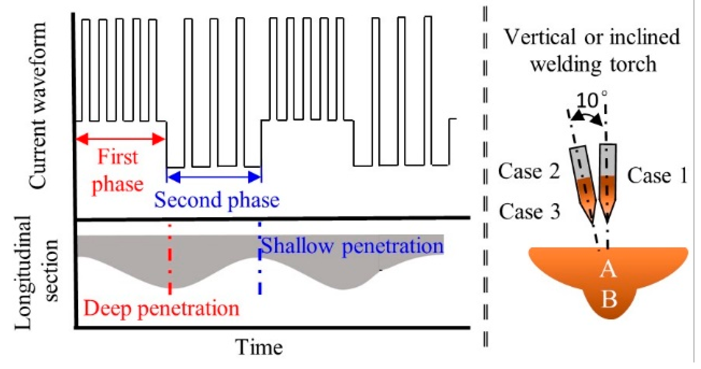
The, 6XXX series of aluminum alloys are widely used in different fields because of their high strength-to-weight ratio [1,2]. These components are often fabricated into industrial structures by fusion welding processes [2]. Gas metal arc welding (GMAW) is an important fusion welding method of joining aluminum alloys [3]. In GMAW, the weld profile and microstructure are strongly affected by the molten pool behavior [4], which in turn is strongly affected by various driving forces, such as the arc pressure, plasma shear force, Marangoni force and electromagnetic force (EMF) [4,5]. However, in GMAW, the molten pool behavior is more complex because it involves the impingement of molten droplets into the weld pool, relative to gas tungsten arc welding which has no droplet impingement [4,6]. Hu and Tsai [6] found that a detached droplet is accelerated by the plasma arc during its flight toward the workpiece. When a droplet was transferred into the molten pool, the flow pattern was mainly determined by the droplet impact [4,7]. Cao et al. [8] simulated two different metal droplet velocities and found that the weld penetration was primarily determined by the metal droplet impact force. Moreover, by developing a unified model considering both the heat and mass transfer in the electrode, arc plasma and molten pool, Fan and Kovacevic [9] found that the penetration of the weld pool was mainly determined by the impingement of droplets. After droplet impingement, a “crater” is created in the weld pool [10], and the finger-like penetration (FLP) geometry of the weld bead is formed [8,11]. As shown in the lower right corner of Figure 1, the weld profile with the FLP in the transverse section was characterized by a shallow and wide penetration in the upper region, labeled zone A in Figure 1, and a deep and narrow penetration in the lower weld [12], labeled zone B in Figure 1. Zone B is known as FLP.
Although the geometric characteristics of the FLP are well recognized, the grain morphology of this type of weld bead has not been fully investigated. Previous research has mainly focused on various methods for the refinement of grains, such as ultrasonic stirring [13], pulsed ultrasonic stirring [14], electromagnetic stirring [15], and arc oscillation [16], and grains in the central part of a weld bead which were often set as the focus and evaluated indicator for the validity of a method. This may be because grains along a weld wall have been widely recognized as having a columnar morphology [17,18]. However, a weld bead with FLP characteristics displays a quite different result in this study. So far, the difference in grain morphology between the walls of the FLP and the walls of the shallow region has not been reported, nor has the mechanism causing the variation.
As mentioned above, droplet impingement plays a significant role in determining the flow pattern, temperature distribution and resultant weld profile and grain morphology. In this study, we focus on the weld profile and grain morphology of aluminum alloys based on droplet impingement with the welding torch held perpendicular to the base metal. Subsequently, to investigate the effect of the impingement direction, the welding torch is held at a 10° inclination in the transverse section. Finally, to further understand how droplet impingement is affected by penetration depth, the double pulsed-gas metal arc welding (DP-GMAW) method, which can produce both deep and shallow penetration in a single travel, was employed.
2. Materials and Methods
Bead-on-plate welding experiments were conducted on aluminum alloy AA6061 base metal (250 × 60 × 3 mm3) using ER4043 filler wire. The chemical compositions of alloys AA6061 and ER4043, are provided in Table 1 [1]. The DP-GMAW process parameters are given in Table 2. Pure argon was coaxially supplied as a shielding gas at a flow rate of 18 L/min. After welding, the specimens were cut along the deepest and shallowest transverse cross sections of the welds, as schematically shown by the center line in the lower part of Figure 1. The samples were obtained from 3 cases, as shown in Figure 1, case 1: the sample with deepest penetration and welding torch perpendicular to the base metal; case 2: the sample with deepest penetration and a 10° inclination of the welding torch to the base metal; and case 3: the sample with shallowest penetration and a 10° inclination of the welding torch to the base metal. The samples were ground and polished with colloidal silica and were subsequently etched for metallographic analysis using the standard Keller agent for 20 s.
DP-GMAW was employed to obtain different depth penetrations under the same condition. DP-GMAW was characterized by its special current waveform with two sets of pulsing current: the first phase (namely the thermal peak), with a high mean current, produced deep penetration, and the second phase (namely the thermal base), with a low mean current, produced shallow penetration. The current waveform and temporal variations of the longitudinal sections of the welds produced by DP-GMAW, are schematically illustrated on the left-hand side of Figure 1, from which it can be seen clearly that the penetration increased when welding with a high mean current in the first phase, and decreased when welding with a low mean current in the second phase.
3. Results and Discussion
3.1. Welding Torch Perpendicular to the Base Metal
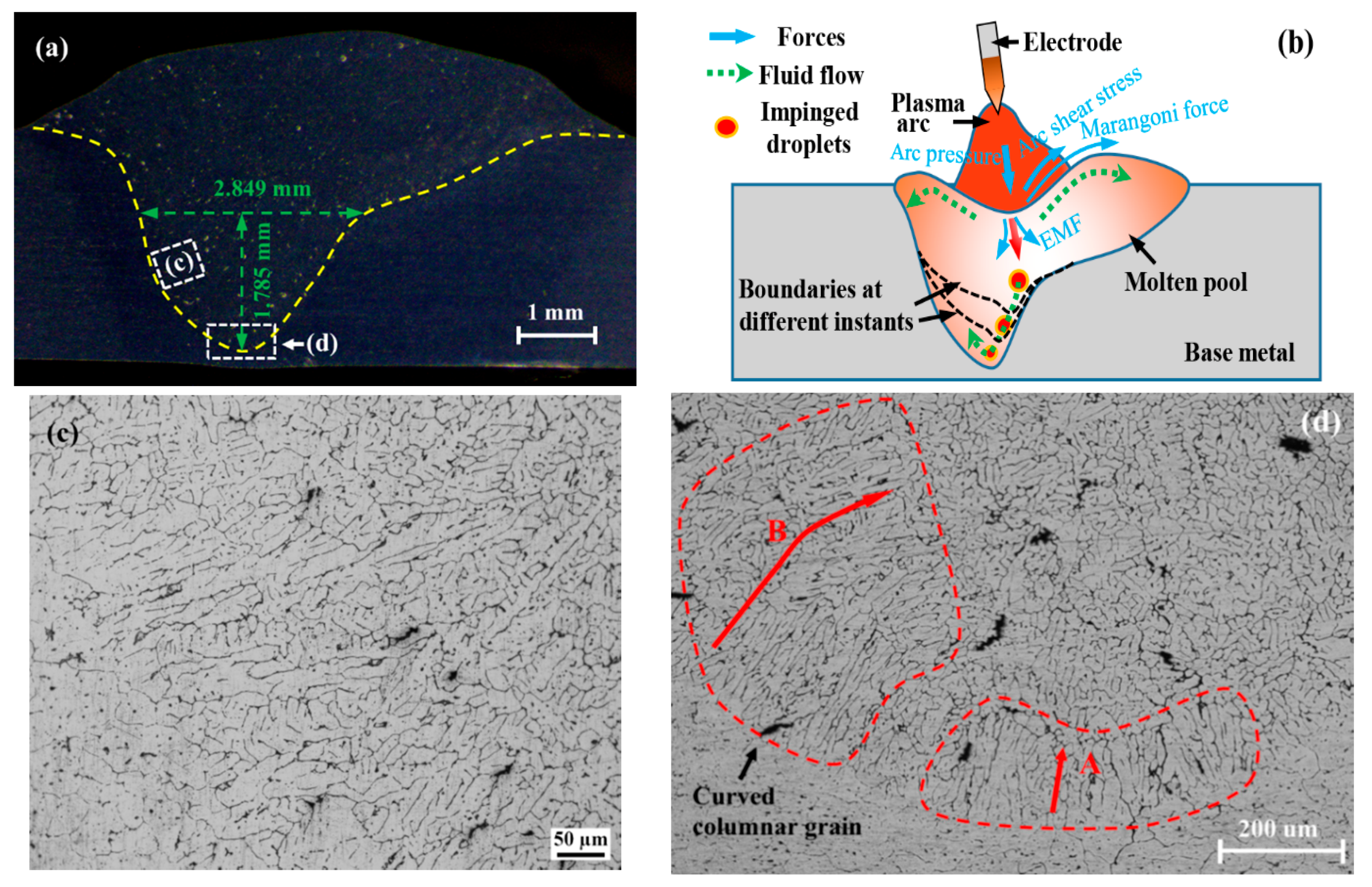
When the welding torch was perpendicular to the top surface of the base metal in the transverse section (case 1), FLP was commonly observed in the fusion zone [8,12], as shown in Figure 2a. The formation of the weld profile with FLP was mainly due to the combination of the outward flow of the molten metal at a shallow level, and downward flow at a deep level. The outward flow was responsible for the wide but shallow penetration, and the downward flow was responsible for the deep and narrow penetration. Under the combined driving forces, including a drag force induced by the difference in tangential velocity between the plasma and the molten pool, and a Marangoni force caused by surface tension and its spatial gradient [5,19], the molten metal flowed outward. Next, more of the solid base metal at the liquid/solid interface was molten, thereby increasing the width of the weld pool. The heat input occurred over a large area, which could not melt deeper because of the lack of a powerful downward flow. Therefore, a wide but shallow concave region formed.
The remarkable surface depression caused by arc pressure following a Gaussian distribution thinned the fluid layer between the arc and solid base metal [20], thus decreasing the buffering of the weld puddle from the droplet impact [4,21]. The acceleration of the droplets due to the plasma drag force [6], combined with the weakened buffering effect of the weld puddle, made it easier for droplets to reach the bottom boundary of the weld pool, even with substantial redundant momentum. Moreover, because of the heat input before droplet impingement, the solid bottom was heat-softened [22]. Thus, when an accelerated and superheated droplet impinges on a thin fluid layer, it flows downward and crashes against the solid but already-softened bottom; creating a crater. Note that the heat and momentum carried by droplets weakened and the size of the droplets decreased as they flowed downward, and after crashing, the droplets scattered into pieces to flow to both sides [23], as represented by the green dashed arrows in Figure 2b. Then, the crater became increasingly deep under the successive impingement of droplets, as shown by the black dashed line in Figure 2b. Finally, a deep penetration formed. Meanwhile, because of the significant difference in velocity between the droplet and the neighboring liquid in the molten pool and the reduced viscosity caused by increased temperature, only a small fraction of the fluid near the droplets was heated and accelerated, and this fluid could only melt a narrower area than at the shallow level. Therefore, a distinct separating landmark, namely a sharp inflection point (SIP), formed between the shallow and the FLP levels.
The grain morphology along the different walls of the molten pool differed considerably, including both columnar grains (Figure 2c) at the shallow level, and refined equiaxed dendrites (Figure 2d) at the FLP level. The difference in grain morphology could be ascribed to the contradiction between the room required by the momentum obtained by the molten metal from droplet impingement and the space which could be provided by the FLP. When the weld pool provides space far beyond that required, the fluid carrying heat flux does not have sufficient momentum to run violently throughout the space; thus, the growth of grains will not be interrupted. In contrast, when the molten metal acquires more momentum to flow but only a small region can be supplied for that flow by the molten pool, then the grain growth will be disturbed and refined by the momentum and heat which is brought by droplet impingement. Because many researchers have provided details of how fluid flow refines grains, as was determined in References [14,16], a detailed description of the process was not provided here. As shown in Figure 2b, at the shallow level, the weld pool was sufficiently wide that the fluid flow which was driven by the combined drag force and Marangoni force was not sufficiently powerful to run violently throughout the shallow level, particularly at the walls. Thus, the grains grew into a columnar morphology without interruption by the fluid flow. Compared to the redundant room for flow at the shallow level, the flow of molten metal was limited to a deep and narrow space. In addition to the limited space, the downward flow was driven by the powerful high-speed droplets [4,8]; thus, the contradiction was intensified significantly, and the more powerful fluid had the ability to run violently throughout a limited FLP. Subsequently, the grain growth was continuously interrupted, causing grains along the walls of the FLP to refine and transit to equiaxed dendrites.
3.2. Welding Torch Inclined in the Transverse Section
The profile of the weld pool was significantly different when the welding torch was set at an angle of 10° from the center line in the transverse section (case 2), with the disappearance of the SIP on the non-action side (Figure 3a). This phenomenon possibly arose because when the welding torch is inclined, heat input becomes asymmetric about the longitudinal central plane, outlined in References [24,25], as shown in Figure 3b. Because of the asymmetric heat input, more base metal melted on the left side of the axial line of the welding wire than on the right side, causing the bottom to be uneven. Thus, when the droplet impacted the uneven bottom of the weld pool, the more molten region (in this case, the left side) had a considerably lower resistance to the impingement because of its liquid state than the solid-state region on the right side [11,26]. Thus, instead of impacting both sides at the same order of magnitude, as in case 1, the droplet impacted harder on the left side due to its weak resistance. The original uneven solid bottom became more uneven because of the additional hard impact and heat input from droplet impingement. Next, an asymmetric crater formed because the left side bottom was considerably lower than the right side bottom; this crater could serve as a confined channel to redirect the droplet impingement [27]. Then, when another droplet impinged, it tended to crash heavily against the solid walls on the impact action side (IAS), thus melting and paring the solid-state wall, whilst flowing downward until finally smashing against the bottom. The dimensions of the FLP were measured with 2.849 mm in width and 1.785 mm in depth, and the width-to-depth aspect ratio was 1.596. Next, the boundaries were expanded downward in the same mode, as depicted by the black dashed lines in Figure 3b. However, there was no crashing against the other side wall during the entire downward flow process because its liquid state facilitated the flowability for droplet impingement. This lack of crashing may have accounted for the remnant SIP on the IAS, and the disappearance of SIP on the non-impact action side (NIAS).
Figure 3c,d demonstrates the grain morphology distribution characteristics at different positions of the weld pool walls. The grains along the wall of the IAS in the FLP, where droplet impact occurred, were refined with no discernible difference from the same area in case 1. However, the columnar grains emerged along the walls of the NIAS in the FLP (Figure 3c), whereas refined grains were observed at the same position in case 1. This phenomenon may have occurred because both the momentum and heat obtained from the superheated droplets were consumed most at, and shortly after crashing against the wall of the IAS until they reached the bottom. This interpretation is supported by Figure 3d, which clearly demonstrates the variation trend of columnar grains in the bottom region. The figure shows that the columnar grains with small sizes emerged in the bottom region (zone A in Figure 3d) because of the weak existence of droplet impingement. Afterward, when the fluid flowed to the NIAS region, the droplet-impingement-driven-flow had nearly exhausted of all its momentum and heat, losing its ability to run violently throughout the FLP region, thus providing the grains in this region with the opportunity to grow without interruption into a columnar morphology with greater size in the NIAS region (zone B in Figure 3d). The columnar grains in the NIAS region grew in a curved pattern consisting of a multi-segment line, rather than along a single straight line from the fusion boundary toward the center of the molten pool. DebRoy and his coworkers [23] claimed that the local solidification direction of a columnar grain changing with the movement of the molten pool was responsible for this phenomenon. In contrast to their experiment with gas tungsten arc welding, there was droplet impingement involved in this study, which played a critical role in determining the direction in which the temperature gradient had the maximum value. Hence, in this study, the droplet impingement was likely responsible for the emergence of curved grains due to its role in changing the temperature gradient and thus the local solidification direction.
3.3. Shallow Penetration with an Inclined Torch
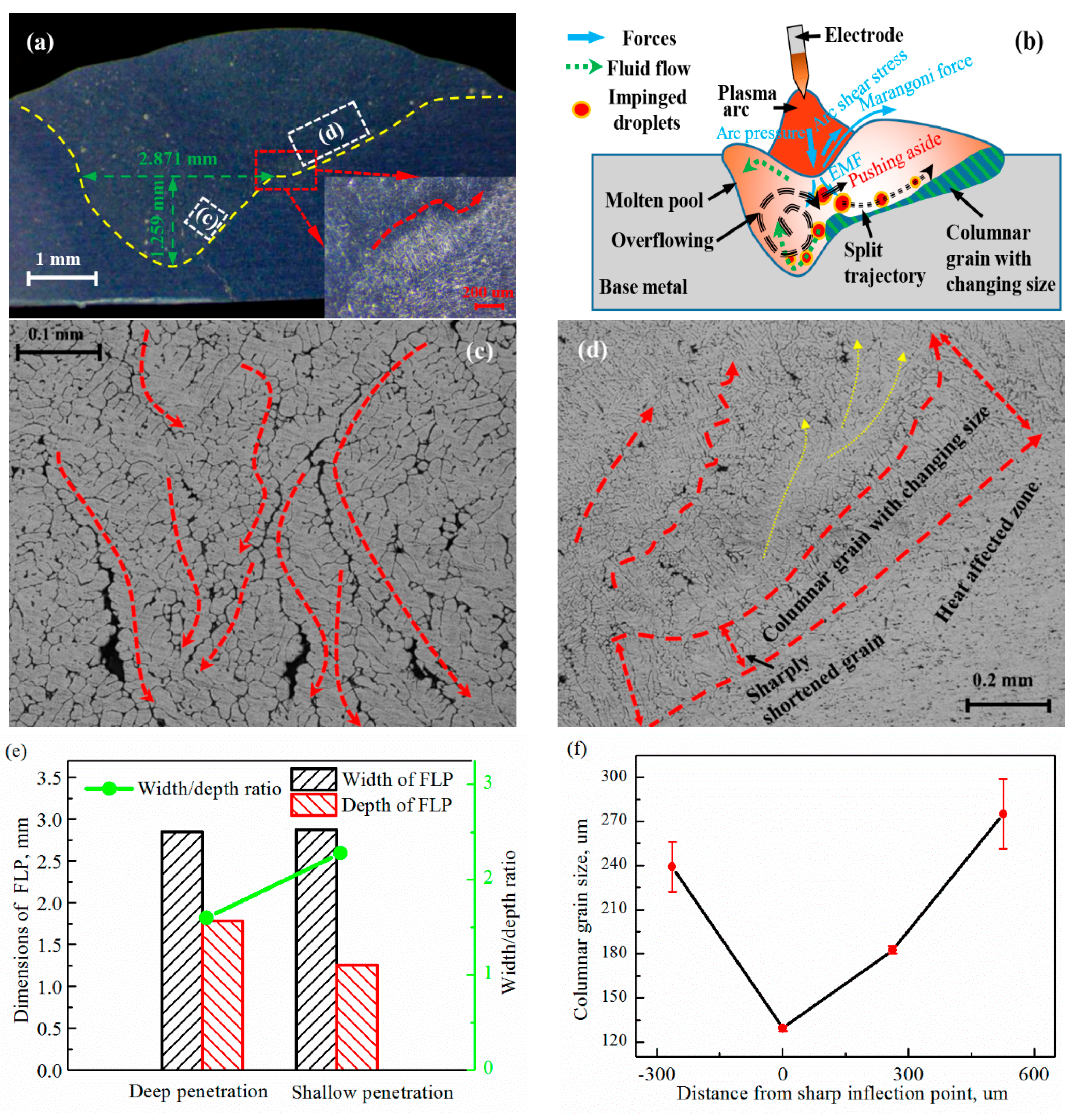
When the welding current entered into the small current phase with an inclined welding torch (case 3), the weld penetration depth decreased from 1.785 mm to 1.259 mm, whilst the width increased slightly from 2.849 mm to 2.871 mm compared with case 2, as shown by the dimensions of the FLP in Figure 3a for case 2 and Figure 4a for case 3. This significant decrease in penetration could be ascribed to the change in flow pattern in the molten pool, as schematically illustrated by Figure 4b. The figure shows that the trajectory of flow driven by droplet impingement was split into two branches at the SIP when the penetration depth decreased: (i) a branch flowing downward to the bottom, as depicted by the red curved arrows which represented the signs of the trajectories created by repeated droplet impingement (Figure 4c), and (ii) another branch flowing upward along the wall of the shallow level, as indicated by the gradually enlarged grain size with increased distance from the SIP (Figure 4d), which could also be interpreted as the outline of many droplet impingements. This change in flow pattern may have resulted from the constantly varying contradiction between the space provided for liquid flow and the space required by the momentum of flow propelled by droplet impingement. When the droplet impinged into the weld pool, it impacted and peeled the walls and then crashed against the bottom, as in case 2. However, because of the reduced penetration depth, the room supplied was far less than required, instantly intensifying the contradiction dramatically. As a result, the shrunken FLP region could no longer hold the violent flow, which caused molten metal to overflow the FLP region [6,24], as schematically illustrated by the dashed circle arrow in Figure 4b. The overflowing effect could be proven by the width-to-depth aspect ratio [7]. In this study, the FLP aspect ratio increased from 1.596 to 2.281, an increase of 42.9 percent, due to the width being enlarged slightly, whereas the penetration was dramatically reduced by 41.7 percent compared to case 2, as shown in Figure 4e. The overflowing fluid then further exerted its influence on the trajectory of the impinging droplets by pushing them aside to the upward direction (Figure 4b). In the shallow level, the fluid flowed upward along the wall driven by electromagnetic forces (EMF) [25]; this flow may have acted as an inducing flow for droplet impingement. Hence, once pushed aside, the droplets were more involved in, and ultimately converged with the upward flow driven by EMF, as indicated by upward black dashed arrows.
The upward flow shaped the grain morphology along the wall into three stages (Figure 4d): large size before the impact point (IP), reduced size at the IP and in a near neighboring region, and large size again far after the IP. The variation in the grain size with increased distance from the SIP, as illustrated by Figure 4f, may have resulted from the corresponding change in flow magnitude [3]. Different regions suffered different order-of-magnitude impacts and heat inputs from the droplets. The area before the IP suffered slightly and then the grain grew up, whereas the size of the grains at the IP decreased sharply to approximately half of that in the area before the IP, as shown by the local magnified image in Figure 4a and the optical micrograph in (Figure 4f,) which may have been because this area was impacted directly and heavily by droplet impingement, which carried abundant heat and momentum. From another perspective, the shortened columnar grains in the IP region along the upward wall (Figure 4d) provided evidence that droplet impingement had the ability to refine grains directly through impact. Because of the gradually attenuated impact and heat with increasing distance from the IP, the grain size increased again. In fact, the outline of the changing grain size was the trajectory of droplet impingement, as indicated by the other red dashed arrows in Figure 4d. However, the outline was not shaped into the final curve by one single droplet impingement; each time a droplet impinged, the outline was prolonged slightly, as indicated by the yellow curved arrows in Figure 4d. After many droplet impingements, the outline accumulated to the final curve.
When the trajectory of droplet impingement shifted upward, the violent flow in the FLP level gradually diminished because of the lack of sustained bulk momentum input [24], which in turn lowered the space requirement, and reduced the contradiction between the generated and required space. As a result, space with the same size in the FLP level regained the ability to accommodate the reduced magnitude of liquid flow, ending the overflow. This lack of overflow diminished the effect of pushing aside, and thus, the droplet suffering non-pushed effects impinged back into the FLP region again. Then, the already-weakened violent flow in the FLP level was strengthened again, as was the subsequent effect of pushing aside. Therefore, the trajectory of droplet impingement was pushed upward once more. As a result, the cyclic alternative shift between the downward and upward directions was triggered. When droplets were flowing downward, the grains in the upper molten pool continued to grow, which may have accounted for the distance between the curved arrows in Figure 4d.
The grains at the SIP between the separate trajectories survived to grow into a columnar morphology with a considerably greater size than in the neighboring region, as presented by the local magnified image of the region, indicated by the red rectangle in Figure 4a. This enlargement may have been due to the sensitivity of the droplet trajectory to the effect of pushing aside. When the effect of pushing aside was strengthened slightly by the enhanced overflow, the trajectory was shifted significantly in the upward direction. Conversely, the slightly weakened effect pulled droplet impingement considerably downward. Therefore, the region between the trajectories remained unaffected, and avoided a severe impact and heat input from powerful droplet impingement. Hence, the larger columnar grains survived this process.
4. Conclusions
In summary, our findings revealed the significant role of droplet impingement in determining the weld pool profile and grain morphology in the welding of aluminum alloys. The main conclusions were as follows:
- The grains along the wall of the FLP region were more refined than those in the shallow region because of the more violent flow driven by droplet impingement running in a confined space created by the FLP. In summary, grain morphology is determined by the magnitude of contradiction between the room required by fluid flow and the space supplied by the weld pool.
- When the torch is inclined, the SIP disappears and the curved columnar grains emerge along the NIAS wall because of the gradually weakened impingement at that location. Then, when the penetration becomes shallow, the trajectory of droplet impingement is split into two branches under the combined effect of pushing aside and inducing flow which is driven by EMF.
- Grains along the wall of the upward branch undergo three stages due to the change in momentum and heat carried by droplets with increasing distance. However, grains before the IP survive to grow into a columnar morphology with a markedly larger size than in the neighboring region because the columnar grain region may not be impacted by droplets, due to the sensitivity of the impingement trajectory to the effect of pushing aside.
- Droplet impingement can refine grains directly through impact, as evidenced by the sharply shortened columnar grain at the impact point in case 3.
Author Contributions
Z.Z. and J.X. conceived and designed the experiments, and wrote the paper; L.J. and W.W. performed the experiments; and all the authors analyzed and discussed the data.
Funding
This work was supported by the High-level Leading Talent Introduction Program of GDAS (No. 2016GDASRC-0106), the National Natural Science Foundation of Guangdong Province (No. 2016A0303117), and Natural Science Foundation of Fujian (No. 2018J01503).
Conflicts of Interest
The authors declare no conflict of interest.
References
- Bardel, D.; Fontaine, M.; Chaise, T.; Perez, M.; Nelias, D.; Bourlier, F.; Garnier, J. Integrated modelling of a 6061-T6 weld joint: From microstructure to mechanical properties. Acta Mater. 2016, 117, 81–90. [Google Scholar] [CrossRef]
- Ambriz, R.R.; Mesmacque, G.; Ruiz, A.; Amrouche, A.; López, V.H. Effect of the welding profile generated by the modified indirect electric arc technique on the fatigue behavior of 6061-T6 aluminum alloy. Mater. Sci. Eng. A 2010, 527, 2057–2064. [Google Scholar] [CrossRef]
- Wang, L.L.; Wei, H.L.; Xue, J.X.; DebRoy, T. A pathway to microstructural refinement through double pulsed gas metal arc welding. Scr. Mater. 2017, 134, 61–65. [Google Scholar] [CrossRef]
- Rao, Z.H.; Zhou, J.; Liao, S.M.; Tsai, H.L. Three-dimensional modeling of transport phenomena and their effect on the formation of ripples in gas metal arc welding. J. Appl. Phys. 2010, 107, 054905. [Google Scholar] [CrossRef]
- Meng, X.; Qin, G.; Zou, Z. Sensitivity of driving forces on molten pool behavior and defect formation in high-speed gas tungsten arc welding. Int. J. Heat Mass Transf. 2017, 107, 1119–1128. [Google Scholar] [CrossRef]
- Hu, J.; Tsai, H.L. Heat and mass transfer in gas metal arc welding. Part II: The metal. Int. J. Heat Mass Transf. 2007, 50, 808–820. [Google Scholar] [CrossRef]
- Fan, H.G.; Kovacevic, R. A unified model of transport phenomena in gas metal arc welding including electrode, arc plasma and molten pool. J. Phys. D Appl. Phys. 2004, 37, 2531–2544. [Google Scholar] [CrossRef]
- Davies, M.H.; Wahab, M.; Painter, M.J. An Investigation of the Interaction of a Molten Droplet with a Liquid Weld Pool Surface: A Computational and Experimental Approach. Weld. J. 2000, 79, 18s–23s. [Google Scholar]
- Cao, Z.; Yang, Z.; Chen, X.L. Three-dimensional simulation of transient GMA weld pool with free surface. Weld. J. 2004, 83, 169s–176s. [Google Scholar]
- Wang, Y.; Tsai, H.L. Impingement of filler droplets and weld pool dynamics during gas metal arc welding process. Int. J. Heat Mass Transf. 2001, 44, 2067–2080. [Google Scholar] [CrossRef]
- Kim, C.H.; Zhang, W.; DebRoy, T. Modeling of temperature field and solidified surface profile during gas–metal arc fillet welding. J. Appl. Phys. 2003, 94, 2667–2679. [Google Scholar] [CrossRef]
- Cheon, J.; Kiran, D.V.; Na, S.J. CFD based visualization of the finger shaped evolution in the gas metal arc welding process. Int. J. Heat Mass Transf. 2016, 97, 1–14. [Google Scholar] [CrossRef]
- Yuan, T.; Kou, S.; Luo, Z. Grain refining by ultrasonic stirring of the weld pool. Acta Mater. 2016, 106, 144–154. [Google Scholar] [CrossRef] [Green Version]
- Wang, J.; Sun, Q.; Liu, J.; Wang, B.; Feng, J. Effect of pulsed ultrasonic on arc acoustic binding in pulsed ultrasonic wave-assisted pulsed gas tungsten arc welding. Sci. Technol. Weld. Join. 2016, 22, 465–471. [Google Scholar] [CrossRef]
- Li, Y.; Zhang, Y.; Bi, J.; Luo, Z. Impact of electromagnetic stirring upon weld quality of Al/Ti dissimilar materials resistance spot welding. Mater. Des. 2015, 83, 577–586. [Google Scholar] [CrossRef]
- Yuan, T.; Luo, Z.; Kou, S. Mechanism of grain refining in AZ91 Mg welds by arc oscillation. Sci. Technol. Weld. Join. 2016, 22, 97–103. [Google Scholar] [CrossRef]
- Kumar, R.; Dilthey, U.; Dwivedi, D.K.; Ghosh, P.K. Thin sheet welding of Al 6082 alloy by AC pulse-GMA and AC wave pulse-GMA welding. Mater. Des. 2009, 30, 306–313. [Google Scholar] [CrossRef]
- Wei, H.L.; Elmer, J.W.; DebRoy, T. Origin of grain orientation during solidification of an aluminum alloy. Acta Mater. 2016, 115, 123–131. [Google Scholar] [CrossRef] [Green Version]
- Fan, H.G.; Kovacevic, R. Droplet Formation, Detachment, and Impingement on the Molten Pool in Gas Metal Arc Welding. Metall. Mater. Trans. B 1999, 30, 791–801. [Google Scholar] [CrossRef]
- Tanaka, M.; Terasaki, H.; Ushio, M.; Lowke, J.J. A unified numerical modeling of stationary tungsten-inert-gas welding process. Metall. Mater. Trans. A 2002, 33, 2043–2052. [Google Scholar] [CrossRef]
- Wang, L.L.; Lu, F.G.; Cui, H.C.; Tang, X.H. Investigation of molten pool oscillation during GMAW-P process based on a 3D model. J. Phys. D Appl. Phys. 2014, 47, 465204. [Google Scholar] [CrossRef]
- Cai, X.Y.; Lin, S.B.; Fan, C.L.; Yang, C.L.; Zhang, W.; Wang, Y.W. Molten pool behaviour and weld forming mechanism of tandem narrow gap vertical GMAW. Sci. Technol. Weld. Join. 2016, 21, 124–130. [Google Scholar] [CrossRef]
- Guo, H.; Hu, J.; Tsai, H.L. Formation of weld crater in GMAW of aluminum alloys. Int. J. Heat Mass Transf. 2009, 52, 5533–5546. [Google Scholar] [CrossRef]
- Cho, D.W.; Song, W.H.; Cho, M.H.; Na, S.J. Analysis of submerged arc welding process by three-dimensional computational fluid dynamics simulations. J. Mater. Process. Technol. 2013, 213, 2278–2291. [Google Scholar] [CrossRef]
- Cho, D.W.; Na, S.J. Molten pool behaviors for second pass V-groove GMAW. Int. J. Heat Mass Transf. 2015, 88, 945–956. [Google Scholar] [CrossRef]
- Liu, J.W.; Rao, Z.H.; Liao, S.M.; Tsai, H.L. Numerical investigation of weld pool behaviors and ripple formation for a moving GTA welding under pulsed currents. Int. J. Heat Mass Transf. 2015, 91, 990–1000. [Google Scholar] [CrossRef]
- Wang, L.; Wu, C.S.; Gao, J.Q. Suppression of humping bead in high speed GMAW with external magnetic field. Sci. Technol. Weld. Join. 2016, 21, 131–139. [Google Scholar] [CrossRef]
Figure 1.
Schematic diagram of the current waveform and longitudinal sections of the double pulsed-gas metal arc welding (DP-GMAW) weld pool and the inclination of the welding torch.
Figure 1.
Schematic diagram of the current waveform and longitudinal sections of the double pulsed-gas metal arc welding (DP-GMAW) weld pool and the inclination of the welding torch.

Figure 2.
Welding torch perpendicular to the surface of the base metal in the transverse section. (a) Molten pool profile; (b) schematic diagram of the molten pool behavior; (c) columnar grain at the shallow level; (d) refined grain at the finger-like penetration (FLP) level.
Figure 2.
Welding torch perpendicular to the surface of the base metal in the transverse section. (a) Molten pool profile; (b) schematic diagram of the molten pool behavior; (c) columnar grain at the shallow level; (d) refined grain at the finger-like penetration (FLP) level.

Figure 3.
Welding torch inclined from the center line in the transverse section. (a) Molten pool profile with the sharp inflection point (SIP) not present on the non-impact action side (NIAS); (b) schematic diagram of the molten pool behavior; (c) columnar grain on the NIAS in the FLP level; (d) shortened columnar grain on the impact action side (IAS) at the shallow level.

Figure 4.
Welding torch inclined from the center line in the transverse section. (a) Molten pool profile; (b) schematic diagram of the molten pool behavior; (c) signs of downward flow; (d) signs of upward flow; (e) width, depth and width/depth ratio of the FLP; (f) columnar grain size along the upward wall.


Table 1.
Chemical compositions of AA6061 and ER4043 (wt%) [1].
Table 1.
Chemical compositions of AA6061 and ER4043 (wt%) [1].
| Material | Mg | Si | Fe | Cu | Mn | Cr | Al |
|---|---|---|---|---|---|---|---|
| AA6061 | 1.02 | 0.75 | 0.45 | 0.25 | 0.06 | 0.05 | Bal. |
| ER4043 | 0.05 | 5.60 | 0.80 | 0.30 | 0.05 | – | Bal. |
Table 2.
Welding process parameters for DP-GMAW.
| Process Parameters | Value |
|---|---|
| Mean voltage (V) | 21.7 |
| Mean current (A) | 96 |
| Wire diameter (mm) | 1.2 |
| Welding speed (mm/s) | 59 |
| Wire feeding rate (mm/s) | 2.8 |
| First phase current (A) | 114 |
| Second phase current (A) | 78 |
| First phase time (ms) | 180 |
| Second phase time (ms) | 180 |
© 2018 by the authors. Licensee MDPI, Basel, Switzerland. This article is an open access article distributed under the terms and conditions of the Creative Commons Attribution (CC BY) license (http://creativecommons.org/licenses/by/4.0/).
Share and Cite
MDPI and ACS Style
Zhang, Z.; Xue, J.; Jin, L.; Wu, W. Effect of Droplet Impingement on the Weld Profile and Grain Morphology in the Welding of Aluminum Alloys. Appl. Sci. 2018, 8, 1203. https://doi.org/10.3390/app8071203
AMA Style
Zhang Z, Xue J, Jin L, Wu W. Effect of Droplet Impingement on the Weld Profile and Grain Morphology in the Welding of Aluminum Alloys. Applied Sciences. 2018; 8(7):1203. https://doi.org/10.3390/app8071203
Chicago/Turabian StyleZhang, Zhanhui, Jiaxiang Xue, Li Jin, and Wei Wu. 2018. "Effect of Droplet Impingement on the Weld Profile and Grain Morphology in the Welding of Aluminum Alloys" Applied Sciences 8, no. 7: 1203. https://doi.org/10.3390/app8071203
Note that from the first issue of 2016, this journal uses article numbers instead of page numbers. See further details here.