A New Passive Islanding Detection Solution Based on Accumulated Phase Angle Drift


1
College of Electronics and Information Engineering, Tongji University, Shanghai 201804, China
2
Smart Protection and Control, Schneider-Electric (China) Co. Ltd., Shanghai 201203, China
*
Author to whom correspondence should be addressed.
Appl. Sci. 2018, 8(8), 1340; https://doi.org/10.3390/app8081340
Submission received: 9 July 2018
/
Revised: 25 July 2018
/
Accepted: 7 August 2018
/
Published: 10 August 2018
(This article belongs to the Special Issue Active Distribution Network)
Abstract
:Featured Application
Utilities prefer the passive islanding detection solution which is cost-efficient and easy to deploy. A new passive islanding detection solution based on the accumulated phase angle drift is proposed to improve the sensitivity and reliability of the existing passive solutions.
Abstract
The existing passive methods for islanding detection are mainly based on the detection of voltage and frequency deviation after islanding, using protections such as voltage vector shift (VVS) and rate of change of frequency (ROCOF). Although there are reported issues with these passive methods such as inherent non-detection zones and nuisance trips, utilities prefer the passive methods due to the low cost and simplicity of deployment. In this paper, one composite passive islanding detection method is presented. It tracks the voltage phase angle, the system frequency, and ROCOF every power cycle. If three phase voltage vectors shift in the same direction and the rotated angle values are balanced, the calculation of the accumulated phase angle drift (PAD) will be initiated. This calculation continues until the ROCOF measurement is below the ROCOF setting threshold. If the accumulated phase angle drift reaches the set angle threshold, the condition for islanding is claimed. The performance of this composite method is verified under different scenarios based on Matlab Simscape multidomain physical systems and practical waveforms recorded from sites. Although there are still non-detection zones, this composite PAD solution has better sensitivity than existing VVS and ROCOF methods and is stable under external system faults.
1. Introduction
During recent years, distributed generation (DG) has spread rapidly. There are more and more DG units interconnected with the distribution network. The high penetration of DG units causes some challenges to the protection of the distribution network. One concern is unintentional islanding which maybe cause safety hazards. Islanding detection is an important requirement and the detection of an unintentional islanding condition should be made within a maximum of 2 s [1,2].
There are many solutions for islanding detection. These methods can be summarized as passive methods, active methods, and communication-based methods. Passive methods are based on the local measurements of the system quantities which maybe change during the transition from interconnected to islanding condition, such as voltage magnitude deviation, voltage vector shift, frequency deviation, and rate of change of frequency. If the active power and reactive power are exactly matched between the generations and loads in the islanded network, the passive methods will fail to detect islanding. This means that there are inherent non-detection zones (NDZs) for these passive methods based on local measurements. Some other passive methods based on wavelet design [3], fuzzy rules [4], and artificial neural networks [5] are also proposed. A passive islanding detection using an accumulated phase angle drift has been proposed [6] where the phase angle drift calculation is based on the estimation of the main grid frequency, but the related field tests demonstrated that this method cannot ensure stability under system frequency fluctuation [7]. Another new passive method has been proposed which defines the three phase voltage indexes as the main discriminative quantity based on the high sampling frequency [8]. Although the performance of this islanding detection method is good during simulation tests, it is difficult to apply the proper voltage index setting in practical applications.
Active methods normally require the continuous interaction with the output of DG. These methods inject small signals into the distribution system or force the DG to a slightly abnormal status. The connected network and islanded network have different response characteristics to these active disturbances from the DG. With low frequency current injection, the active rate of change of frequency ROCOF relay for islanding detection is proposed by Reference [9]. Among these active methods, reactive power variation based the islanding detection method is one of the effective ways of drifting frequency during islanding [10]. However, the active methods are only used for inverter-based DG.
The fast development in communication technologies makes the wide-area information exchange possible [11]. The communication-based methods apply the communications between the utility grid and the DG, such as direct transfer trip or phasor measurement unit. The communication-based methods are most reliable and NDZs can be reduced to zero, but the cost is expensive when a dedicated communication channel is required. The direct transfer trip solution is complex when there are many devices upstream which can switch and cause islanding [12]. Islanding detection based on the phasor measurement unit is proposed [13,14]. It mainly applies the frequency difference and change of angle difference to detect islanding. The main problem of the solutions in References [13,14] is the time delay caused by the phasor report latency.
Although there are inherent non-detection zones, the passive methods do not affect the normal operation of the DG system and are easy to implement. Due to the trade-off between accuracy and cost, passive methods, such as ROCOF and voltage vector shift (VVS) relays are normally used for islanding detection [15,16]. The overall performances on islanding detection of ROCOF relay and VVS relay depend on the condition of power imbalance. Moreover, mal-operations of VVS relay have been reported at the external system fault inception and the instant of fault clearance [17]. The ROCOF relay maybe become ineffective for islanding detection when the operation time delay is applied and the ROCOF value is not stable at the initial stage after islanding [18]. For VVS and ROCOF relays, there are user concerns on both sensitivity and reliability. There are obvious benefits if the existing passive methods can be improved to provide better sensitivity and reliability for islanding detection.
This paper presents a composite passive islanding detection method which includes both VVS relay and ROCOF relay operating principles. The operation criterion is based on the accumulated phase angle drift. The dynamic response of inverter-interfaced DGs mostly depend on the control algorithms of the inverters. Normally, the inverter controllers will become unstable shortly after loss of the reference signal due to loss of main grid. Islanding detection is relatively easy for inverter-interfaced DGs and the inverter controller provides the islanding detection function. Besides, both ROCOF relay and VVS relay are applicable to inverter-interfaced DGs. The proposed solution is an improvement based on the existing ROCOF relay and VVS relay. To simplify the analysis, this proposed islanding detection solution is introduced in the presence of synchronous generator type DG, but it is also applicable for inverter-interfaced DGs. One similar passive islanding detection solution is presented in Reference [19]. Compared with Reference [19], this paper improves the solution, and provides more details on the application, full simulation tests, and prototype tests.
This paper is organized as follows: Section 2 introduces the principles of ROCOF relay and VVS relay in the presence of synchronous generator type DG. Section 3 and Section 4 introduces the principle and application guide of the proposed composite islanding detection method. Section 5 presents the verification results of the proposed method based on Matlab Simscape simulation tests. Section 6 presents the playback tests with the practical waveforms recorded from the engineering sites. Section 7 concludes this paper.
2. Principles of ROCOF and VVS Relays
Both ROCOF and VVS relays are applicable to all kinds of DG types. To simplify the analysis, the following subsections introduce the principles of ROCOF and VVS relays based on synchronous machines.
2.1. ROCOF Relay
When the DG unit is running in parallel with the main power grid, the frequency is governed by the main grid. When the main grid is lost, the power imbalance between load and generation could cause the change of frequency. The rate of change of frequency can be expressed as [20]:
where is the total load of DG; is the total active power output of DG; is the rated capacity of DG; H is the inertia constant of DG; and is the rated frequency.
Equation (1) assumes that the machine is running at rated frequency and the time interval is short enough that AVR and governor dynamics can be ignored. If the measured rate of change of frequency after the islanding exceeds the threshold of ROCOF relay, it will operate and the islanding condition is detected. When the DG capacity closely matches the local load, the rate of change of frequency is very small. So inherently there are NDZs for ROCOF relay. Besides, some system events, such as normal heavy load switching, fault clearance or transient voltage disturbance, can cause significant transient frequency fluctuations and on occasions the df/dt value can exceed the ROCOF relay setting. To enhance the reliability, normally a short time delay (such as 0.5 s) is applied for the ROCOF relay. However, it has also reported that ROCOF relay maybe become ineffective when time delay is applied [18].
2.2. VVS Relay
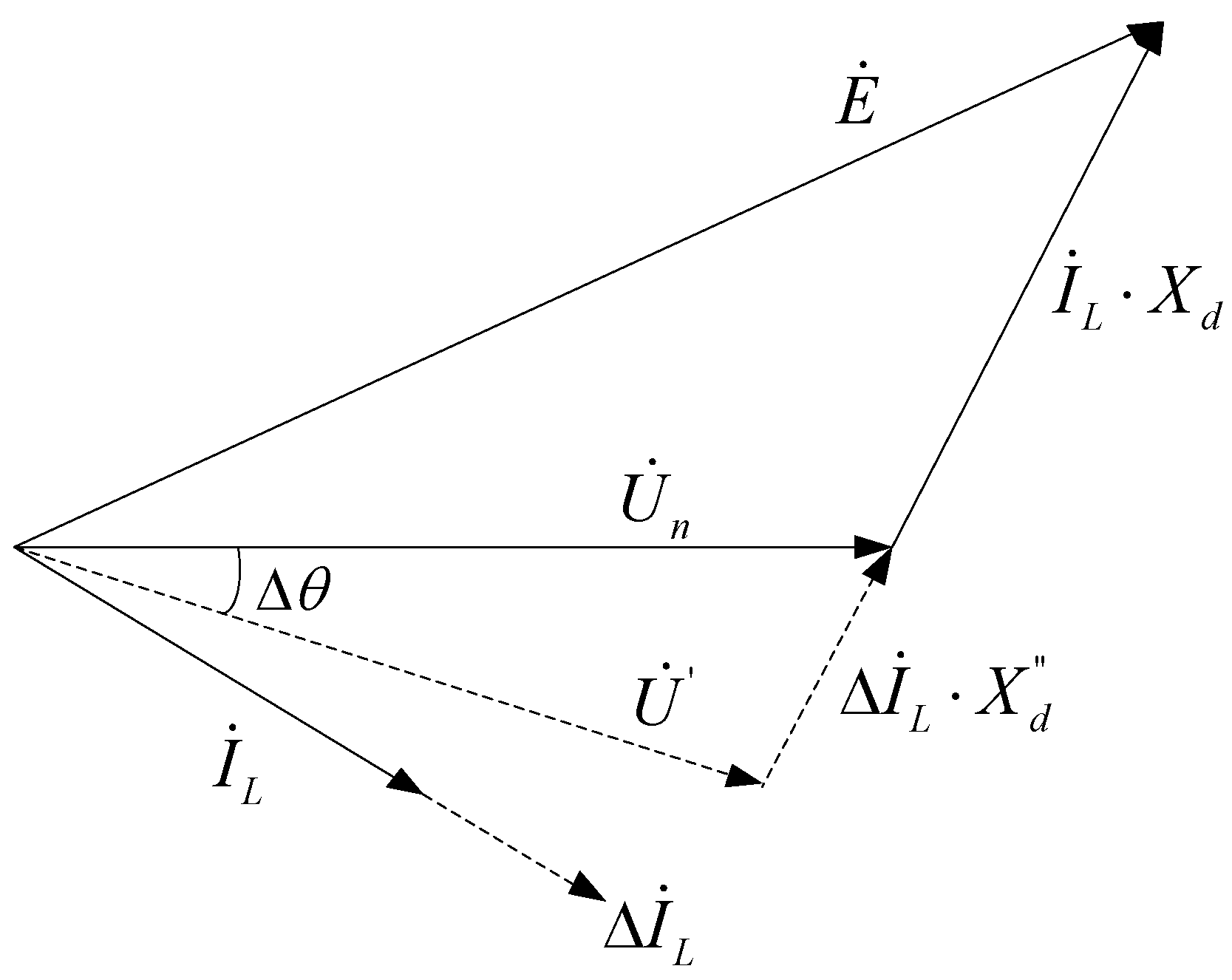
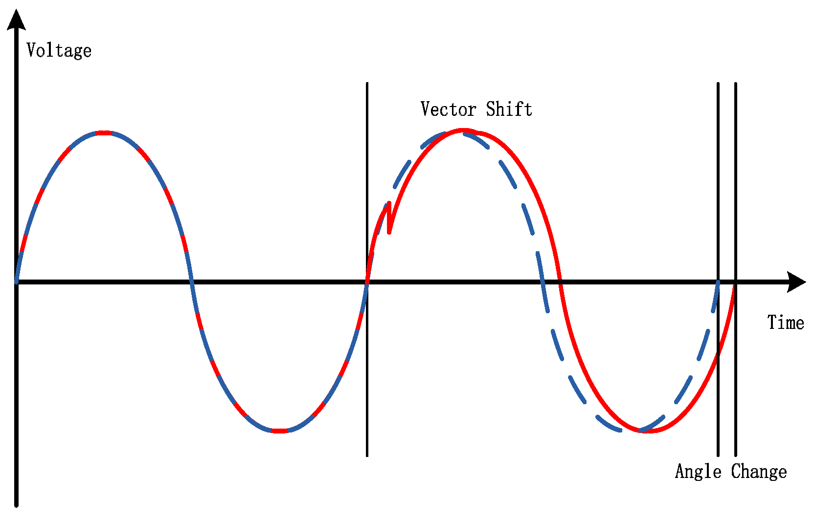
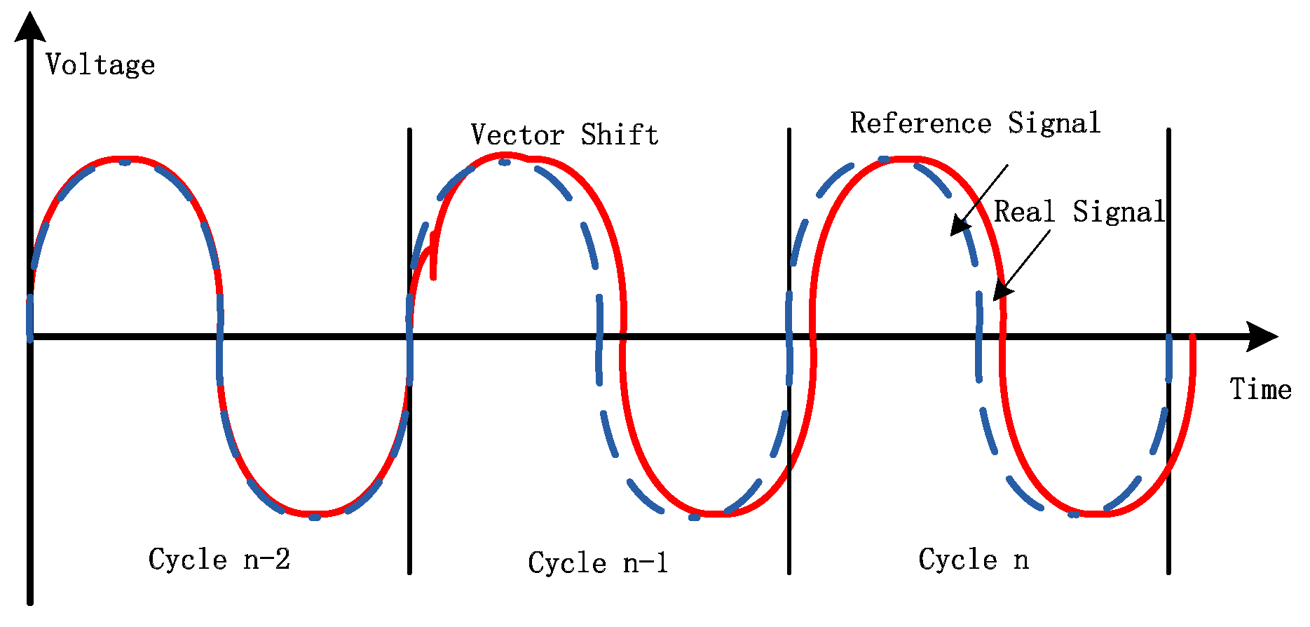
Voltage vector shift (VVS) is also referred to as vector surge or phase jump. The VVS relay monitors the phase angle change of the local voltage in real time. Under the steady state condition, the phase angles calculated each cycle are the same and the voltage cycle length is also fairly constant. Hence the phase angle change is zero. However, at the instant of islanding, the current will change suddenly if the power between load and generation does not closely match. The sudden change of current will cause a sudden jump of the voltage vector, as shown in Figure 1 and Figure 2.
In Figure 1, is the rated electromotive force; is the rated voltage; is the new voltage after the vector shift; is the synchronous reactance; is the sub-transient reactance; is the load current; and is the current change.
The resultant voltage vector is dependent on the current change and the sub-transient reactance of the machine, which is the reactance of the generator under a sudden load change. The voltage phase angle change can be approximately expressed as:
If the generator is running at the rated condition before the voltage vector shifts, then Equation (2) can be approximately deduced as:
In Equation (3), is active power change; and is the rated active power of generator.
Here it is necessary to emphasize that VVS relay in a practical engineering application usually detects the sudden change of the voltage phase angle due to the sudden change of load current. However, a change of system frequency can also cause the change of the voltage cycle length and hence the change of phase angle between two consecutive cycles. The value of angle change due to the frequency change is expressed as:
In Equation (4), where is the angle change due to frequency change; is the rate of change of frequency; is the phase angle calculation interval.
When the rate of change of frequency is 1.0 Hz/s, the angle change between two consecutive power cycles is only . However, the typical angle threshold of VVS relay is from 6.0° to 10.0°. Hence, the VVS relay is not sensitive to the voltage phase angle change caused by change of frequency alone [21]. In some of the literature [15,16,22], the VVS relay is described to detect the phase angle change caused by the change of frequency. Such analysis is not consistent with the operating principle of practical commercial VVS relays.
If the current change at the instant of islanding is large enough to cause a voltage phase angle change larger than the angle threshold, the VVS relay will operate and islanding is detected. In addition to the inherent NDZ, the VVS relay cannot effectively distinguish islanding conditions from system faulted conditions. At the instant of system faults or fault clearance, the VVS relay can sense the sudden change of the voltage phase angle. Other system events, such as load or generation switch operation, could also cause the sudden change of voltage phase angle. To enhance the reliability and reduce the possibility of nuisance tripping, it requires a relatively higher angle setting for the VVS relay. Hence the VVS relay is relatively less sensitive for islanding detection.
3. Composite Islanding Detection Solution
3.1. Basic Principle
From the analysis in Section 2, the VVS relay monitors the sudden voltage phase angle change at the instant of islanding and ROCOF relay monitors the change of frequency after islanding. One example for an islanding condition of the synchronous generator is presented in Figure 3 with voltage cycle length before and after islanding. The voltage cycle length is measured by the zero-crossing detection method. The islanding condition happens at time 0 s. The voltage cycle length suddenly increases from 20 ms to 20.13 ms which means the voltage vector shifts about 2.6° due to the sudden current change. After islanding, the cycle length increases and the frequency decreases. The rate of change of frequency remains greater than 0.5 Hz/s until time 0.6 s. Hence the sudden islanding condition in this example results in a voltage jump and then the frequency changes.
Compared with the voltage phase angle at the instant of islanding, there is an accumulated phase angle drift due to the frequency change. The accumulated phase angle drift is expressed as:
In Equation (5), where f(t0) is the frequency at the instant of islanding.
The state machine of the composite phase angle drift (PAD) solution is shown in Figure 4.
The basic principle includes four main criteria:
- If any voltage phase angle changes per cycle are larger than the threshold , the stable frequency and phase angles just before the phase angle jump is recorded.
- If three phase angle changes are in the same direction, the calculation of the phase angle drift is initiated. The calculation of the phase angle drift is based on the recorded last stable frequency value, as Equation (5).
- If the maximum rate of change of frequency in five power cycles is less than the threshold , which means the frequency is almost stable, the calculation of the accumulated phase angle drift is terminated and the value of is reset to zero.
- If the accumulated phase angle drift is larger than threshold , the islanding condition is claimed.
3.2. Detailed Design of Composite Solution
One typical application scenario for islanding is loss of main grid connection resulting from a system fault. The circuit breaker in the incoming feeder is disconnected to clear the fault and then the DG unit is isolated. The power system status is described as transitions between the following states (1) Healthy → (2) Faulted → (3) Islanding. If an obvious power imbalance exists in the islanded power system, the voltage phase angles in status (1) and (3) will be different. So, the voltage phase angle and system frequency just before the fault inception shall be recorded. The recorded voltage phase angles in status (1) shall be continuously compared with subsequent voltages angles calculated each power cycle, to detect the voltage angle changes in the same direction and then to initiate the calculation of accumulated phase angle drift.
The voltage phase angles are calculated from a one cycle Discrete Fourier Transformer (DFT) based on phase to phase voltages, which is more stable under earth fault conditions in an isolated system. The real-time frequency tracking is applied and the frequency measurement is calculated per power cycle. The voltage phase angles , , are calculated per power cycle.
3.3. Start Criterion
The “Normal Status” and “Abnormal Status” of the power system are defined. The initial state of the power system without fault is in “Normal Status”. The voltage phase angle changes under the “Normal Status” are expressed as follows:
In Equation (6), where is the phase angle calculated at the n cycle; is the phase angle calculated at the n − 2 cycle.
The phase angle calculation is based on full cycle DFT. When the vector shifts in cycle n − 1 as shown in Figure 5, the DFT calculation with the samples in cycle n − 1 is not accurate. So the calculation of the phase angle changes shall apply and for better accuracy.
If Equation (7) is satisfied, the state of the power system is switched into “Abnormal Status” from “Normal Status”.
Here is the angle change threshold.
The voltage phase angle changes under the “Abnormal Status” are expressed as follows:
In Equation (8), is the phase angle calculated at the n cycle; is the last phase angle calculated in the “Normal Status”.
3.4. Phase Angle Drift Calculation Criterion
A special status of “Abnormal Status” is defined as “Balanced Abnormal Status” when the three phase voltages shifts are well balanced. If Equations (9)–(11) are satisfied, the state of the power system is “Balanced Abnormal Status”.
Equations (10) and (11) ensure that the voltage vector shifts are three-phase balanced.
If the power system is in “Balanced Abnormal Status”, the calculation of the accumulated phase angle drift will be initiated as Equation (12).
In Equation (12), is the last frequency measurement calculated in the “Normal Status”; is the phase angle calculation interval (such as 20 ms in 50 Hz system and 16.67 ms in 60 Hz system); is the index number of the first power cycle after “Balanced Abnormal Status” is detected. If the accumulated phase angle drift is higher than the setting , the islanding condition is claimed.
3.5. Reset Criterion
When the frequency is stable and the maximum absolute value of the rate of change of frequency in the last five power cycles is less than threshold, the calculation of the accumulated phase angle drift is terminated and the state of the power system returns to “Normal Status”. To improve the reliability, the time window for calculation should not be too short. The reset criterion is expressed in Equation (13).
3.6. Explanation of the Design
In general, the power shall be balanced on all three phases whether in a grid-connected or islanding condition. So, if islanding condition happens due to the opening of the interconnection CB, the three phase voltage vectors should shift in the same direction with generally balanced phase angles. However, unbalanced system faults usually cause the three phase voltage vectors to shift in different directions with unbalanced phase angle changes. So, the balanced three phase voltage vectors shifts can be applied to differentiate the islanding condition from the unbalanced system faults.
For three phase system faults, it is possible that the three phase voltage vector shifts are balanced and the calculation of the accumulated phase angle drift is initiated. Normally three phase faults shall be tripped off within 100 ms. Hence, the islanding detection solution should remain stable for at least 100 ms. If there are specific requirements on fault ride through capability of the DG unit, the islanding detection solution shall also remain stable during the required duration. The tripping time of the PAD solution for islanding detection depends on the frequency change caused by the three-phase fault and the accumulated phase angle drift setting.
Some other system events, such as load or generation switching operation, could also cause the balanced three phase voltage vectors shifts and the transient frequency fluctuation. Such events would usually cause a transient but they will not cause the continuous frequency deviation. So, a proper threshold for the accumulated angle drift setting can be applied to differentiate the islanding condition from the normal system operation events.
The calculation of the accumulated phase angle drift is terminated when the max rate of change of frequency in five power cycles is less than the setting . To reset the value of phase angle drift before the system frequency completely settled down is helpful to the stability when the frequency is under a long-time fluctuation with small ROCOF value.
4. Application of Composite PAD Solution
Generally, the passive methods of islanding detection are relatively difficult to set-up the relay exactly, no matter the DG types. The existing ROCOF relay and VVS relay are normally set-up based on the engineering experience. There are three main settings for this new composite PAD solution , , and . This section will introduce the calculation of the proper settings applied to differentiate the islanding condition from the variable system events under grid-connected mode. However, the applicatioin guide for setting calculation could be improved step by step with more engineering experience from the field tests.
4.1. Sudden Phase Angle Change
Unlike the conventional relay, in the new composite PAD method, the detection of voltage vector shifts in same direction is only to initiate the calculation of the accumulated phase angle drift. The main purpose of the setting is to differentiate the islanding condition from the system events, such as frequency excursions.
Considering Equation (3), the angle change is related to the active power imbalance and the sub-transient reactance of the generator. For the generator with damped winding, the typical sub-transient reactance is around 0.2. Taking the synchronization machine in the following simulation section as an example, the sub-transient reactance is 0.23. The angle change under different power imbalance is shown in Table 1.
The default setting for is suggested as small as 1.0° with sensitivity better than 10%. The stable setting for can be 2.0° which can provide better stability. The setting for should be based on the size of the DG units and the analysis of possible power imbalance. Besides, the practical application should comply with the related requirements from the utility. If the sensitivity has higher priority, the setting for can be as small as 1.0° to minimize the non-detection zone. If the stability has higher priority, the worst case of power imbalance in the regional grid should be analyzed and then set suitably with relatively large value.
4.2. Rate of Change of Frequency
For system operation events, such as load or generation switching, which cause the system frequency fluctuation, normally the rate of the change of frequency normally is less than 0.5 Hz/s with relatively large system inertia. If the ratio of the inverter-based DG is relatively higher in the whole power system, the maximum transient ROCOF value will increase. The basic principle is that the setting for is slightly larger than the maximum value of ROCOF due to the planed system operations.
In the UK, G59 [23] recommends the ROCOF settings for loss of main protection is 1.0 Hz/s with 500 ms time delay for the new installed DG units. The ROCOF relay with these recommended settings should be stable for all the manifestations of expected ROCOF and its accompanying voltage vector shift events that are expected on the power system. G59 also recommends the minimum setting for ROCOF is 0.5 Hz/s.
The default setting for is suggested as 0.5 Hz/s. The stable setting for can be 1.0 Hz/s. Even if the transient maximum ROCOF value is larger than the setting , the islanding condition will not be claimed by the PAD solution before the accumulated phase angle shift achieves the threshold .
4.3. Accumulated Phase Angle Drift
The proposed composite PAD solution is immune to unbalanced system faults. However, mal-operation is still possible during the three phase faults. The proper accumulated phase angle drift setting is applied to ensure the stability.
The three-phase fault in the interconnection line of DG unit can break the electrical connection between the DG unit and the utility grid. It is possible that the frequency deviation causes the voltage phase angle drifts during the three-phase fault. The setting for should ensure the stability during the close-up severe three-phase fault for at least 100 ms before the fault clearance. Considering Equation (4), if the rate of change of frequency during the three-phase fault is as high as 10 Hz/s and the fault duration is less than 100 ms, the phase angle drift is: . The default setting for is suggested as 18°. It is possible that ROCOF value is higher than 10 Hz/s if the system inertia is small enough. However, to ensure the system frequency security, the system inertia shall not be too small. Generally, in the practical power system, ROCOF value is no less than 10 Hz/s. Even if ROCOF value is larger than 10 Hz/s, this proposed solution is still applicable with larger phase angle drift settings.
Besides, if there are specific requirements on fault ride through capability of the DG units, the islanding detection solution shall also keep stable during the required duration. Based on the recommended ROCOF settings from G59 [23], 1 Hz/s and 0.5 s time delay which could ensure the stability, the corresponding phase angle drift is: . The stable setting for is suggested as 45°.
5. Simulation Test
The simulation is based on Matlab Simscape multidomain physical systems. The simulation model shown in Figure 6 consists in a 30 MVA gas turbine synchronous machine (SM), local series RL load, connection cables, CBs, 110 kV/10 kV transformer, and the equivalent main grid source of 50 Hz system. The SM system included an exciter with IEEE type AC1A voltage regulator and the gas turbine with governor. The local load and the main grid could be switched off with a Step On signal. The detailed parameters of the simulation model are shown in Table 2.
5.1. Typical Response
The typical response characteristics are from the simulation case where the active power imbalance between SM and local load is −10% after the unintentional opening of CB3 in Figure 6, which causes the loss of the main grid. In this simulation, the reactive power was exactly balanced. This simulation was based on the default settings: , . CB3 was open at the instant 0 s, which means the main grid was lost. The islanding condition wa detected by the proposed composite PAD solution at 0.42 s.
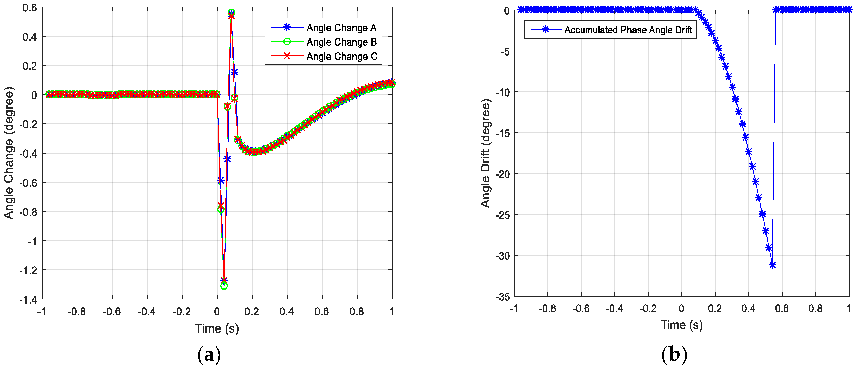
The following from Figure 7a,b and Figure 8a,b present the change of the related electrical quantities before and after loss of main grid. From Figure 7a, at the instant of loss of main grid, these three voltage phase angles changed in the same direction with the values larger than the setting . So, the calculation of accumulated phase angle drift based on the real-time frequency and the frequency value at 0 s was initiated. Figure 7b shows the accumulated phase angle drift. At 0.42 s, accumulated phase angle drift reached the threshold 18°. At 0.52 s, the maximum absolute ROCOF value in five power cycles was below reset setting 0.5 Hz/s. Then the calculation of phase angle drift was terminated.
5.2. Sensitivity-Active Power Imbalance
The sensitivity tests are performed based on both the suggested default settings and the stable settings, as following: , , (default settings); , , (stable settings).
Before the islanding condition, the reactive power was well balanced between SM and local load. The active power imbalance each varied from 50% surplus to −50% deficit. Totally, 12 test cases were created. For all test cases, the trip times of composite PAD solution with default settings and the stable settings, the minimum value of three voltage phase angle changes, the duration when ROCOF value was larger than 0.5 Hz/s and the duration when ROCOF value was larger than 1.0 Hz/s, were recorded, as shown in Table 3.
The minimum angle change values from the simulation tests were compatible with Equation (3). The angle setting in the conventional VVS relay was usually no less than 6.0°. In that case, the conventional VVS relay was not sensitive and the non-detection zone was worse than 40% power imbalance. Besides, the VVS relay usually was susceptible to initiate nuisance tripping due to external system fault. Hence, the conventional VVS relay cannot meet the technical requirements of islanding detection.
From Table 3, even if the power imbalance was as high as 50%, the duration when the value of ROCOF was larger than 1.0 Hz/s was only 480 ms. So in this test environment, based on the recommended settings 1.0 Hz/s and 500 ms time delay for ROCOF relay from G59 [23], ROCOF relay cannot detect the islanding condition with 50% power imbalance.
With the default settings, the non-detection zone of the proposed PAD solution was less than 10% power imbalance. If the local load is very close to the generation, this proposed solution cannot detect the islanding quickly.With the stable settings, the non-detection zone of the proposed PAD solution is less than 20% power imbalance, which is much better than the existing passive islanding detection methods VVS relay and ROCOF relay. Besides, the tripping time of PAD method is much faster than ROCOF relay with 0.5 s time delay.
5.3. Sensitivity-Reactive Power Imbalance
The reactive power imbalance sensitivity tests are based on the default settings: , , .
Before the islanding condition, the active power is well balanced between SM and local load. The reactive power imbalance varies from 100% surplus to −150% deficit. The same test cases are also applied into the conventional VVS relay with angle setting as 6° and ROCOF relay with settings as 0.5 Hz/s and 0.5 s time delay, to compare the sensitivity of different passive islanding detection methods. Totally 8 test cases are created and the test results based on the sensitive settings of PAD solution are shown in Table 4.
The reactive power imbalance does not have direct influence on the frequency of SM. However, reactive power imbalance has influence on the terminal voltage of SM and hence has the indirect influence on the dynamic behavior of voltage-dependent loads, which causes the dynamic frequency response of SM. So, the passive methods, PAD, VVS, and ROCOF, are all not very sensitive to the reactive power imbalance. Compared with VVS and ROCOF relays, the proposed PAD solution has the better sensitivity and faster tripping time.
5.4. Stability under System Fault
The passive islanding detection methods are required to remain stable under the external system fault condition. The mal-operation of the islanding detection could cause the loss of the power from distributed generators, which is detrimental for system stability. The external system fault can happen on the adjacent feeders, the MV busbar, the HV side of the transformer, or the upstream transmission system.
As shown in Figure 6, the simulation model defines the system fault located on the adjacent feeder near the utility substation. During the stability tests, different fault types with different fault resistances are applied to verify the stability of the proposed PAD solution. Generally, it is easier for this proposed solution to remain stable during high impedance faults where the system frequency is almost no change. All these faults happen at 0 s and are cleared at 100 ms. Totally, eight test cases were created and the results are shown in Table 5.
In Table 5, the “fault voltage” means the minimum voltage at the fault location. The voltage measurement at the SM terminal is larger than the “fault voltage” due to the cable impedance. “PAD calculation started?” means if the calculation of accumulated phase angle drift is initiated.
5.5. Stability under Frequency Fluctuation
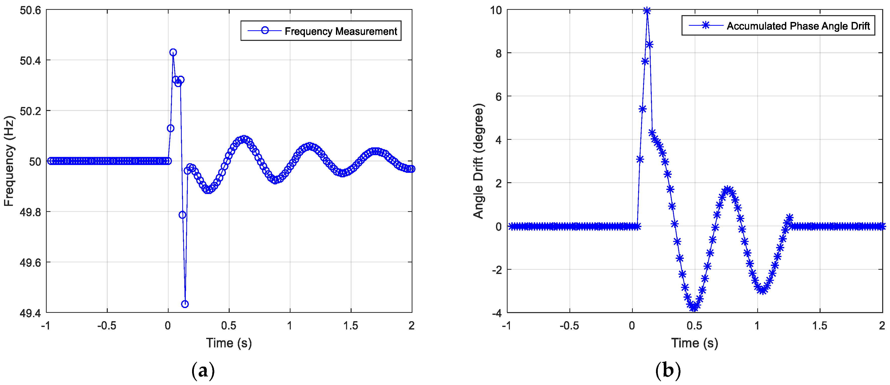
In the power system, frequency fluctuation is possible due to the large load switching on or off. To evaluate the stability under system frequency fluctuation, local load is defined as 400% rated active power of SM in the simulation model. The local load is suddenly switched off, which could cause the frequency fluctuation shown in Figure 10. The frequency is fluctuated in the range from 49.85 Hz to 50.20 Hz (the peak frequency value at the instant of load switching is casued by the angle jump and should be ignored). Then the frequency is converged on 50 Hz. The instant ROCOF value during the decay oscillation is within the range from −2 Hz/s to 1.5 Hz/s (the transient ROCOF values due to the angle jump should be ingored), as shown in Figure 11a. Then the ROCOF value decays to zero. During the frequency fluctuation, the maximum accumulated phase angle drift is about 15°, as shown in Figure 11b. Under this test case, the default settings , , can ensure the stability of the proposed PAD solution.
6. Tests Based on Field Waveforms
This proposed composite PAD solution has been implemented in one commercial relay. The disturbance recorders from the conventional VVS relays installed in the several different sites are used to play back to that relay to evaluate its performance in a real power system. Most of these recorders are triggered by the mal-operations of VVS relay. The default settings are applied during the playback tests.
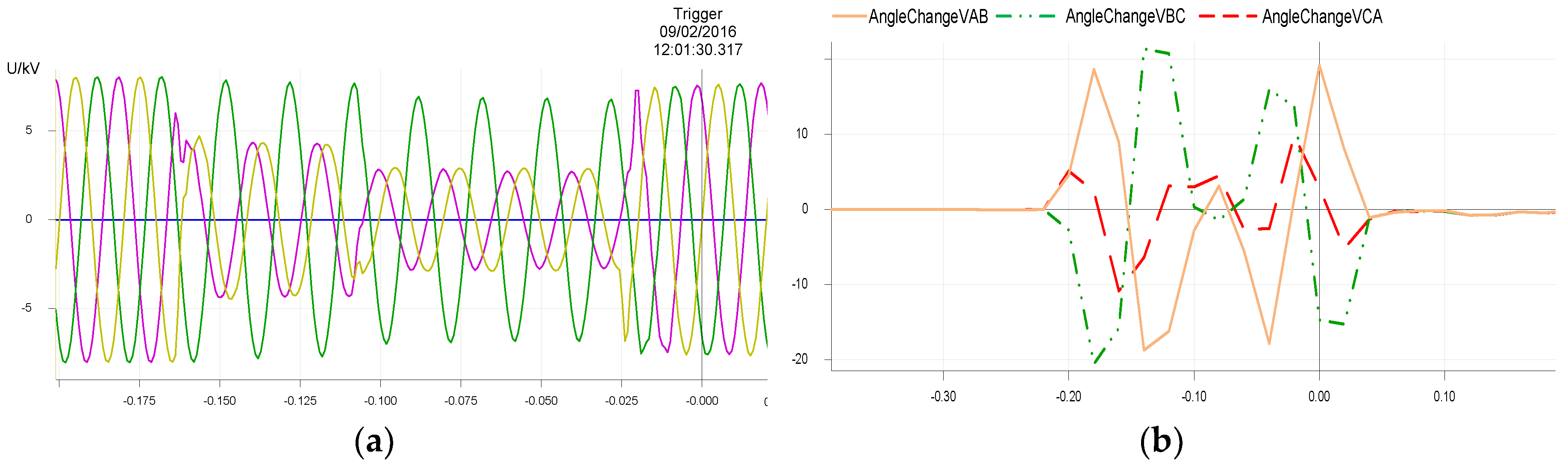
For the unbalanced system faults, the proposed PAD solution can intrinsically keep stable due to the “balanced VVS criteria”. For the waveform recorders of single phase fault and phase to phase fault, three voltage phase changes are not in the same direction. Figure 12a is the waveform recorder from one phase to phase fault and the conventional VVS relay mal-operates at the instant fault clearance. During the playback test with the waveform in Figure 12a, the phase to phase voltage angle changes are recorded by the relay with PAD solution. Figure 12b shows and angle changes are always in the different direction during the AC phases fault. So, the calculation of phase angle drift is never initiated and the PAD solution can keep stable.
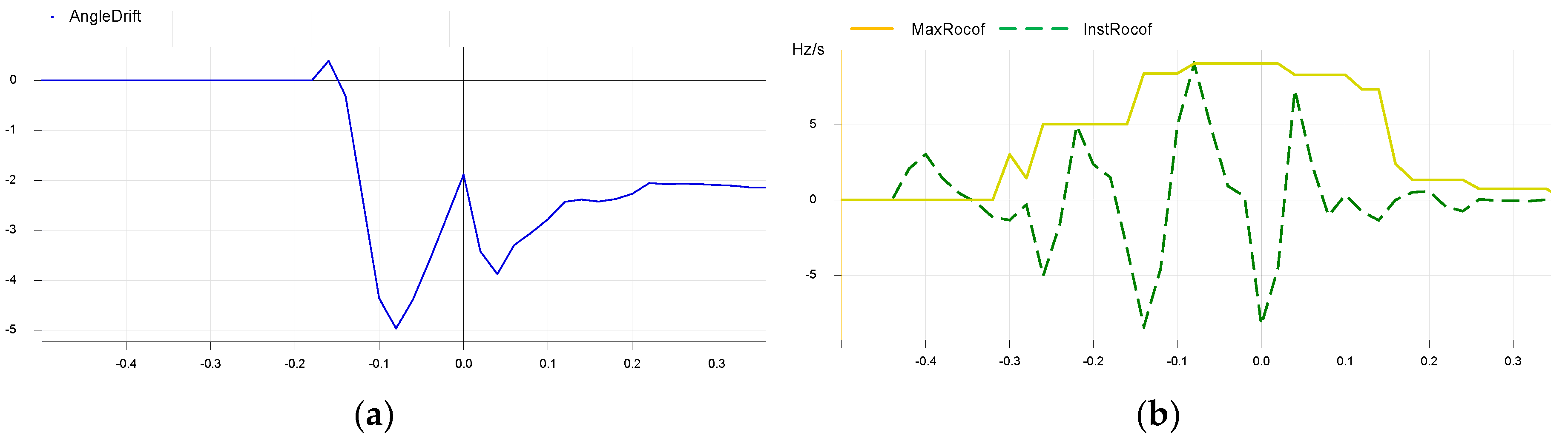
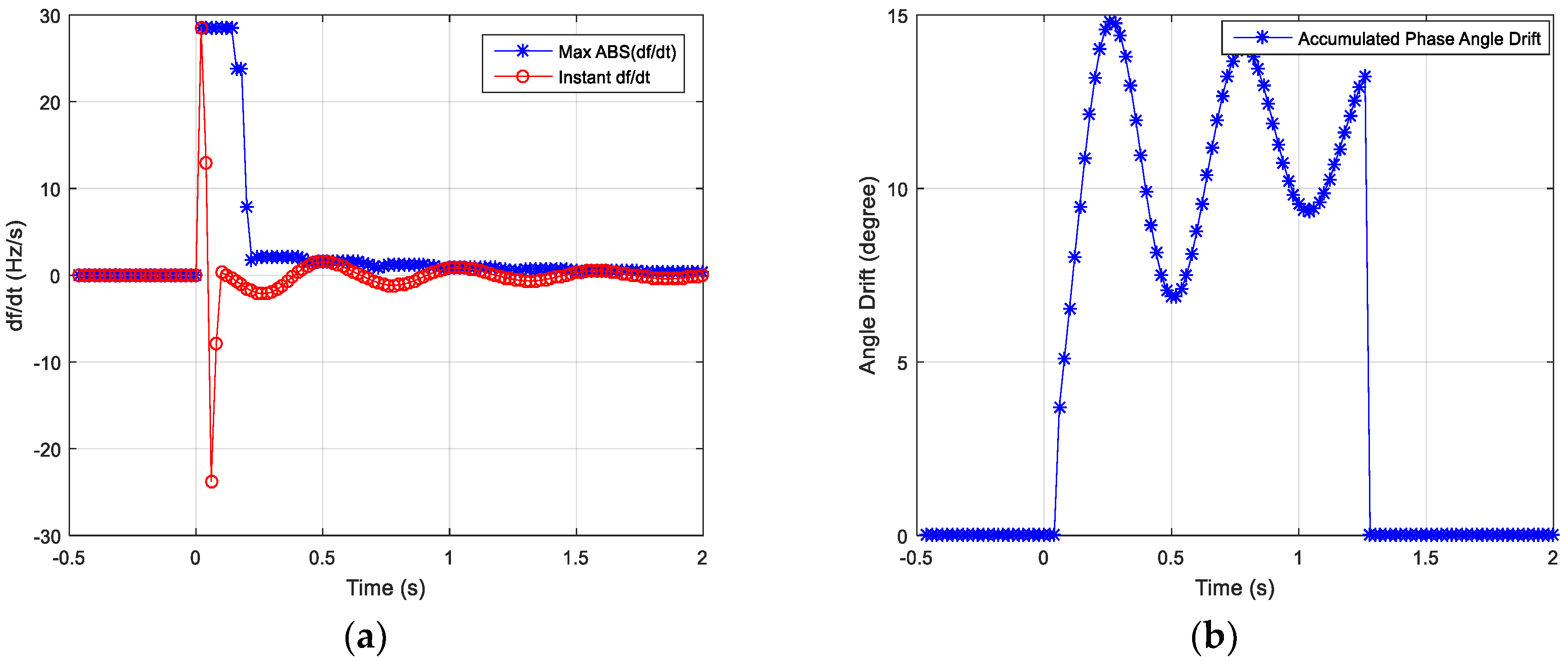
For the three-phase fault, the voltage angle changes are in the same direction and the calculation of phase angle drift would be initiated. So, the setting is expected to ensure the stability during the three-phase fault for at least 100 ms. Figure 13 is the waveform recorder from one three-phase fault and the conventional VVS relay mal-operates at the instant fault clearance. The fault duration is about 135 ms and the fault voltage is about 60% Vn. During the playback test with the waveform in Figure 13, the phase angle drift shown in Figure 14a, the instantaneous ROCOF value and maximum ROCOF value shown in Figure 14b, are recorded by the relay with PAD solution. The maximum angle drift is about 5.0° during the fault and the angle drift is reset about 400 ms after the fault clearance, where the maximum ROCOF value is less than the setting . Generally, the composite PAD solution can remain stable under the three-phase fault with the default phase angle drift setting .
For other waveform recorders, this composite PAD solution can also work correctly. It can detect the islanding condition and remain stable under system fault. It is a pity there is no waveform recorder from the system frequency fluctuation condition. Hence, to fully estimate the performance and to get the setting configuration guide for this composite PAD solution, more field tests are necessary.
7. Conclusions
The VVS relay and ROCOF relay are widely applied to detect the islanding condition. However, the performances of both VVS relay and ROCOF relay are not good. There are inherent non-detection zones and mal-operations are also possible. The proposed composite islanding detection solution in this paper applies both VVS and ROCOF features of the islanding condition. It detects the VVS in the same direction to initiate the calculation of accumulated phase angle drift. It monitors the real-time ROCOF to reset the calculations. The operation criterion is not directly based on VVS or ROCOF, but only based on the accumulated phase angle drift. So more sensitive settings for VVS and ROCOF function can be applied, which can reduce the ratio of NDZ. Significantly, the balanced three phase voltage vector shifts are applied to distinguish the islanding condition from the unbalanced system fault. For three-phase fault, this proposed islanding detection solution can remain stable dependent on the proper angle drift setting. This composite islanding detection solution is verified in Matlab Simscape physical simulation based on the synchronous machine and the practical waveform recorded from different sites. The results show this composite islanding detection solution is stable under the system fault and sensitive for the islanding condition where the power imbalance is more than 10%. The next step of this research is to perform the field tests in as many as possible different countries.
Author Contributions
The paper was a collaborative effort among the authors. Jinlei Xing performed the simulation, analyzed the data, and wrote the paper. Longhua Mu provided critical comments.
Funding
This work was supported in part by the Fundamental Research Funds for the Central Universities of China. Meanwhile, this work was supported in part by Schneider Electric.
Conflicts of Interest
The authors declare no conflict of interest.
References
- IEEE Standard 1547. IEEE Standard for Interconnecting Distributed Resources with Electric Power Systems. 2014. Available online: https://ieeexplore.ieee.org/document/6818982/ (accessed on 7 August 2018).
- Stadler, M.; Cardoso, G.; Mashayekh, S.; Forget, T.; DeForest, N.; Agarwal, A.; Schönbein, A. Value streams in microgrids: A literature review. Appl. Energy 2016, 162, 980–989. [Google Scholar] [CrossRef] [Green Version]
- Alshareef, S.; Talwar, S.; Morsi, W.G. A new approach based on wavelet design and machine learning for islanding detection of distributed generation. IEEE Trans. Smart Grid 2014, 5, 1575–1583. [Google Scholar] [CrossRef]
- Samantaray, S.R.; EI-Arroudi, K.; Joos, G.; Kamwa, I. A fuzzy rule-based approach for islanding detection in distributed generation. IEEE Trans. Power Deliv. 2010, 25, 1427–1433. [Google Scholar] [CrossRef]
- Hashemi, F.; Mohammadi, M.; Kargarian, A. Islanding detection method for microgrid based on extracted features from differential transient rate of change of frequency. IET Gener. Transm. Distrib. 2017, 11, 891–904. [Google Scholar] [CrossRef]
- Yip, H.T.; Millar, G.; Lloyd, G.J.; Dysko, A.; Burt, G.M.; Tumilty, R. Islanding detection using an accumulated phase angle drift measurement. In Proceedings of the 10th IET International Conference on Developments in Power System Protection (DPSP 2010). Managing the Change, Manchester, UK, 29 March–1 April 2010; pp. 1–5. [Google Scholar]
- Lloyd, G.; Hosseini, S.; Chang, A.; Chamberlain, M.; Dysko, A.; Malone, F. Experience with accumulated phase angle drift measurement for islanding detection. In Proceedings of the 22nd International Conference and Exhibition on Electricity Distribution (CIRED 2013), Stockholm, Sweden, 10–13 June 2013; pp. 1–4. [Google Scholar]
- Raza, S.; Arof, H.; Mokhlis, H.; Mohamad, H.; Illias, H.A. Passive islanding detection technique for synchronous generators based on performance ranking of different passive parameters. IET Gen. Transm. Distrib. 2017, 11, 4175–4183. [Google Scholar] [CrossRef]
- Gupta, P.; Bhatia, R.S.; Jain, D.K. Active ROCOF relay for islanding detection. IEEE Trans. Power Deliv. 2017, 32, 420–431. [Google Scholar] [CrossRef]
- Raipala, O.; Makinen, A.; Repo, S.; Järventausta, P. An anti-islanding protection method based on reactive power injection and ROCOF. IEEE Trans. Power Deliv. 2017, 32, 401–410. [Google Scholar] [CrossRef]
- Bo, Z.Q.; Lin, X.N.; Wang, Q.P. Developments of power system protection and control. Prot. Control Mod. Power Syst. 2016, 1, 8. [Google Scholar] [CrossRef]
- Marchesan, G.; Muraro, M.; Cardoso, G. Passive method for distributed-generation island detection based on oscillation frequency. IEEE Trans. Power Deliv. 2016, 31, 138–146. [Google Scholar] [CrossRef]
- Lin, Z.; Xia, T.; Ye, Y.; Zhang, Y.; Chen, L.; Liu, Y.; Tomsovic, K.; Bilke, T.; Wen, F. Application of wide area measurement system to islanding detection of bulk power systems. IEEE Trans. Power Syst. 2013, 28, 2006–2015. [Google Scholar] [CrossRef]
- Liu, X.; Laverty, D.M.; Best, R.J. Principal component analysis of wide-area phasor measurements for islanding detection—A geometric view. IEEE Trans. Power Deliv. 2015, 30, 976–985. [Google Scholar] [CrossRef]
- Alam, M.R.; Muttaqi, K.M.; Bouzerdoum, A. A multifeature-based approach for islanding detection of DG in the subcritical region of Vector Surge Relays. IEEE Trans. Power Deliv. 2014, 29, 2349–2358. [Google Scholar] [CrossRef]
- Freitas, W.; Xu, W.; Affonso, C.M.; Huang, Z. Comparative analysis between ROCOF and vector surge relays for distributed generation applications. IEEE Trans. Power Deliv. 2005, 20, 1315–1324. [Google Scholar] [CrossRef]
- Xing, J.; Ouakli, K. Performance of voltage vector shift relay subjected to unbalanced system fault. In Proceedings of the 12th International Conference for GCC Cigre (GCCPower2016), Doha, Qatar, 8–10 November 2016; pp. 1–6. [Google Scholar]
- Tzelepis, D.; Dysko, A.; Booth, C. Performance of loss-of-mains detection in multi-generator power islands. In Proceedings of the 13th IET International Conference on Developments in Power System Protection (DPSP2016), Scotland, UK, 7–10 March 2016; pp. 1–6. [Google Scholar]
- Xing, J.; Mu, L.; Vivers, P.; Evans, G. A New Islanding Detection Solution Based on Accumulated Phase Angle Drift. In Proceedings of the 14th IET International Conference on Developments in Power System Protection (DPSP2018), Belfast, UK, 12–15 March 2018; pp. 1–8. [Google Scholar]
- Ding, X.; Crossley, P.; Morrow, D. Islanding detection for distributed generation. J. Electr. Eng. Technol. 2007, 2, 19–28. [Google Scholar] [CrossRef]
- Schneider Electric. Technical Manual of Micom P341 Interconnection Protection Relay. 2015. Available online: https://www.schneider-electric.com/en/download/document/P341_EN_M_La7__B0E0_L/ (accessed on 7 August 2018).
- Freitas, W.; Huang, Z.; Xu, W. A practical method for assessing the effectiveness of vector surge relays for distributed generation applications. IEEE Trans. Power Deliv. 2005, 20, 57–63. [Google Scholar] [CrossRef]
- Energy Networks Association. ‘Engineering Recommendation G59 Issue 3 Amendment 3’. September 2015. Available online: https://www.nationalgrid.com/sites/default/files/documents/GC0079%20Annex%203%20Option%201%20G59%20%20proposals%20170731.pdf (accessed on 7 August 2018).
Figure 1.
Voltage vector shift illustration.

Figure 2.
Transient voltage change.

Figure 3.
Voltage cycle length before and after islanding.
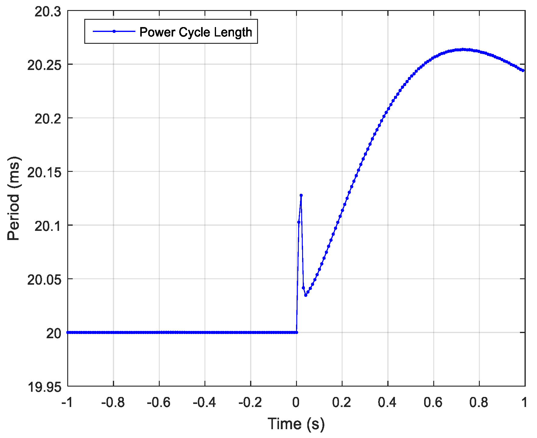
Figure 4.
State machine of composite phase angle drift (PAD) method.
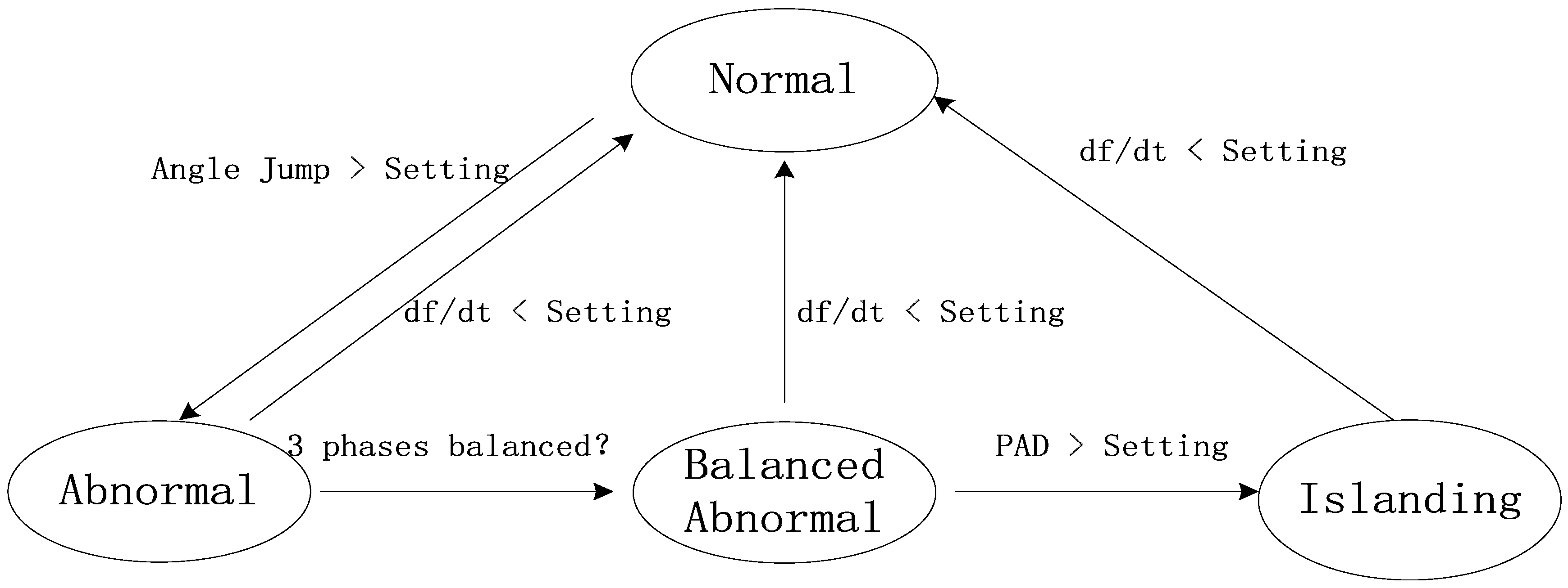
Figure 5.
Phase angle change calculation based on Discrete Fourier Transformer (DFT).

Figure 6.
Simulation model.
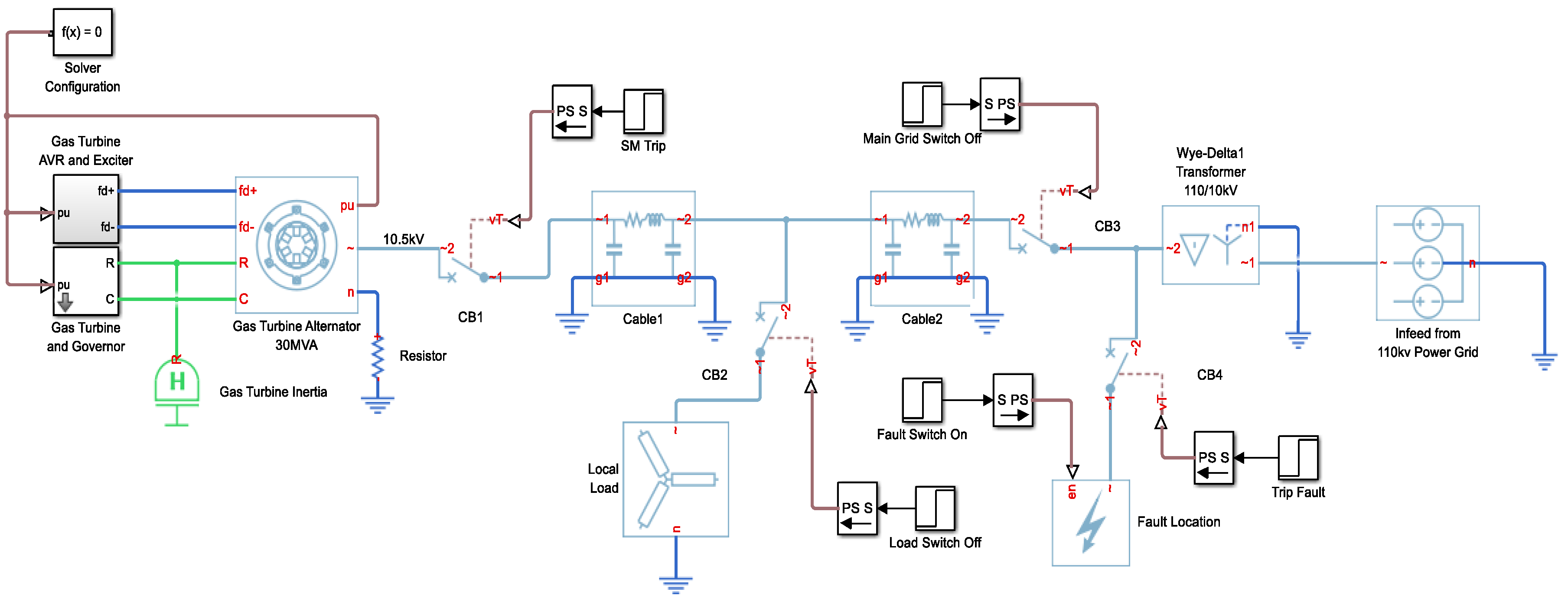
Figure 7.
(a) Angle change; (b) accumulated phase angle drift before and after loss of main grid.

Figure 8.
(a) System frequency measurement change; (b) maximum and instantaneous rate of change of frequency (ROCOF) values before and after loss of main grid.
Figure 8.
(a) System frequency measurement change; (b) maximum and instantaneous rate of change of frequency (ROCOF) values before and after loss of main grid.
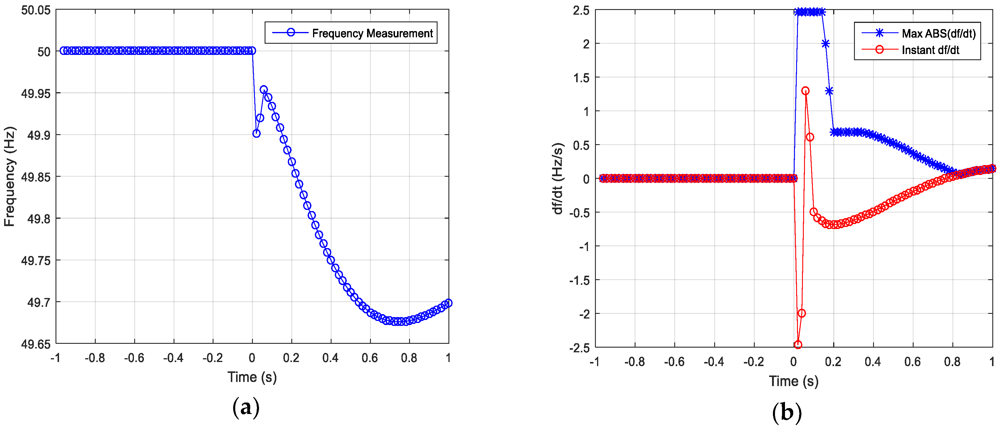
Figure 9.
(a) Frequency measurement; (b) accumulated phase angle drift under three phases fault and the frequency oscillation after fault clearance.
Figure 9.
(a) Frequency measurement; (b) accumulated phase angle drift under three phases fault and the frequency oscillation after fault clearance.

Figure 10.
Frequency measurement under the frequency fluctuation after large load switching off.
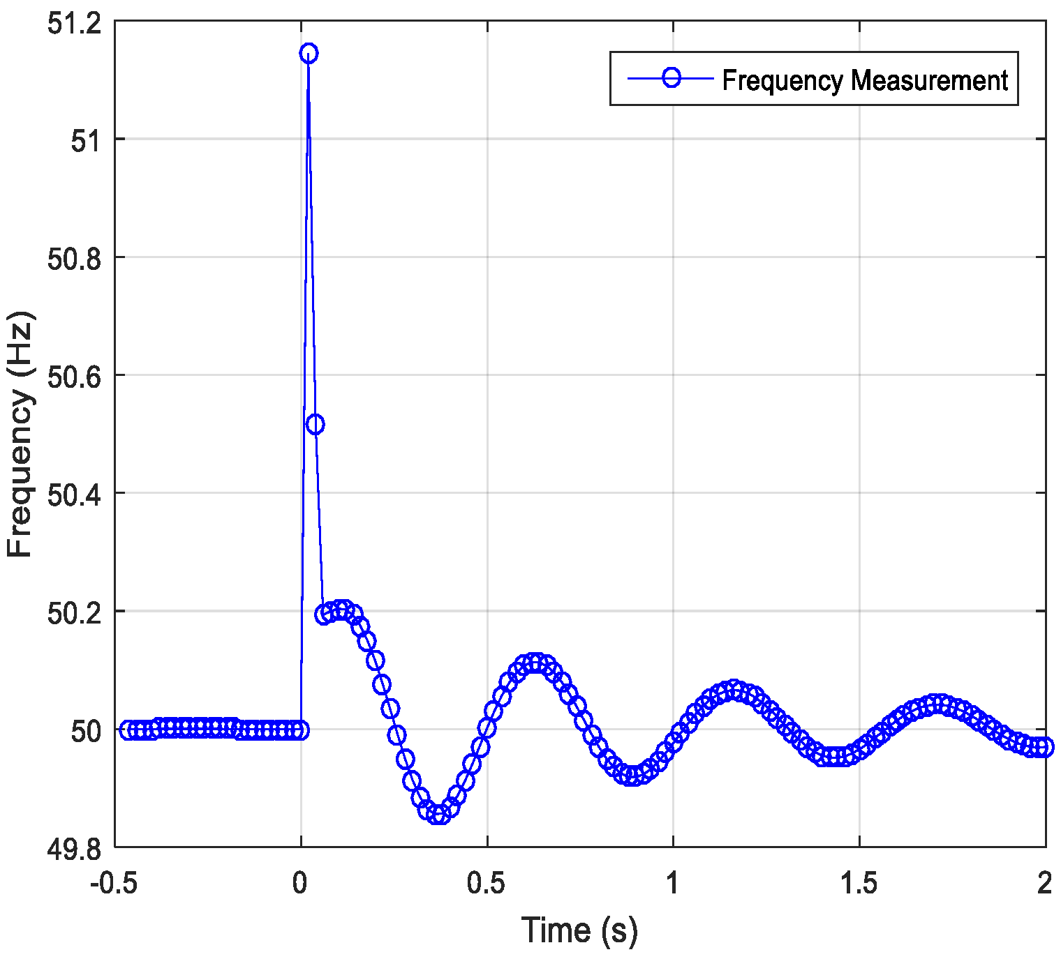
Figure 11.
(a) Maximum and instantaneous ROCOF values; (b) accumulated phase angle drift under frequency fluctuation after large load switching off.
Figure 11.
(a) Maximum and instantaneous ROCOF values; (b) accumulated phase angle drift under frequency fluctuation after large load switching off.

Figure 12.
(a) Waveform recorder from AC phase to phase fault; (b) phase to phase voltage angle change during fault.
Figure 12.
(a) Waveform recorder from AC phase to phase fault; (b) phase to phase voltage angle change during fault.

Figure 13.
Waveform recorder from three-phase fault.
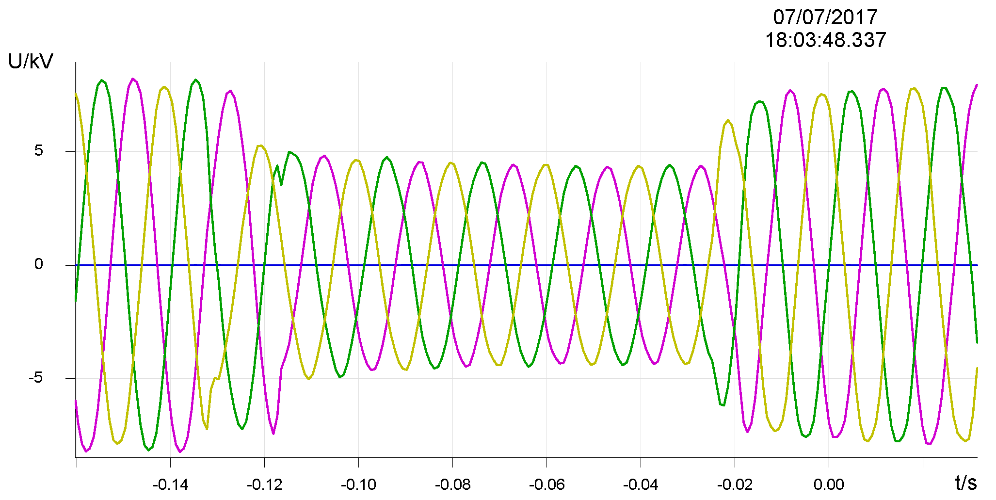
Figure 14.
(a) Phase angle drift; (b) maximum and instantaneous ROCOF values during the three-phase fault.
Figure 14.
(a) Phase angle drift; (b) maximum and instantaneous ROCOF values during the three-phase fault.

Table 1.
Angle change vs. active power imbalance.
| Power Imbalance | Angle Change (°) |
|---|---|
| 50% | 6.6 |
| 40% | 5.28 |
| 30% | 3.96 |
| 20% | 2.63 |
| 15% | 1.98 |
| 10% | 1.32 |
| 5% | 0.66 |
| 2.5% | 0.33 |
Table 2.
Simulation parameters.
| Synchronous Machine | Gas Turbine Inertial |
|---|---|
| Rated Apparent Power: 30 MVA | H = 2.525 s |
| Rated voltage: 10.5 kV | 110/10 kV Transformer (YD1) |
| Rated Field Circuit Current: 200 A | Rated Apparent Power: 100 MVA |
| Xd = 1.81 Xq = 1.76 | Leakage reactance: 0.001 pu |
| Xd’ = 0.3 Xq’ = 0.65 | Leakage resistance: 0.01 pu |
| Xd’’ = 0.23 Xq’’ = 0.25 | Fault |
| Rated Power Factor: 0.8 | Fault type: AG, AB, ABC, ABCG |
| Fault Resistance: 0.1 Ohm, 0.5 Ohm, 0.8 Ohm | |
| Cable 1 | Cable 2 |
| Resistance R = 0.033 Ohm | Resistance R = 0.06 Ohm |
| Inductance L = 0.825 mH | Inductance L = 1.5 mH |
Table 3.
Sensitivity test with the default settings and stable settings for composite PAD solution.
| Active Power Imbalance | Trip Time (ms) Default Settings | Trip Time (ms) Stable Settings | Minimum Angle Change (°) | Duration (ms) for |ROCOF| > 0.5 Hz/s | Duration (ms) for |ROCOF| > 1.0 Hz/s |
|---|---|---|---|---|---|
| 50% | 180 | 280 | 6.9 | 540 | 480 |
| 40% | 200 | 320 | 5.5 | 520 | 440 |
| 30% | 240 | 360 | 4.12 | 480 | 380 |
| 20% | 280 | 440 | 2.75 | 440 | 280 |
| 15% | 320 | No trip | 2.05 | 400 | 120 |
| 10% | 400 | No trip | 1.38 | 280 | 0 |
| −10% | 400 | No trip | − 1.31 | 300 | 0 |
| −15% | 320 | No trip | − 1.96 | 380 | 120 |
| −20% | 280 | 460 | − 2.62 | 460 | 280 |
| −30% | 240 | 360 | − 3.9 | 520 | 400 |
| −40% | 200 | 320 | − 5.2 | 540 | 460 |
| −50% | 180 | 300 | − 6.43 | 560 | 480 |
Table 4.
Sensitivity performance comparison with default settings under reactive power imbalance.
| Reactive Power Imbalance | PAD Trip Time (ms) with Default Settings | VVS Trip Time (ms) | ROCOF Trip Time (ms) |
|---|---|---|---|
| 100% | 260 | No trip | No trip |
| 90% | 280 | No trip | No trip |
| 80% | 300 | No trip | No trip |
| 70% | 340 | No trip | No trip |
| 60% | 380 | No trip | No trip |
| 0~50% | No trip | No trip | No trip |
| −120%~0 | No trip | No trip | No trip |
| −130% | 380 | No trip | No trip |
Table 5.
Stability of PAD solution with default settings under different system faults.
| Fault Type | Fault Voltage | PAD Calculation Started? | PAD Value | PAD Solution |
|---|---|---|---|---|
| AG | 10%Vn | No | 0 | Stable |
| AG | 70%Vn | No | 0 | Stable |
| AB | 10%Vn | No | 0 | Stable |
| AB | 70%Vn | No | 0 | Stable |
| ABG | 10%Vn | No | 0 | Stable |
| ABG | 70%Vn | No | 0 | Stable |
| ABC | 10%Vn | Yes | 9.9° | Stable |
| ABC | 70%Vn | Yes | 4.1° | Stable |
© 2018 by the authors. Licensee MDPI, Basel, Switzerland. This article is an open access article distributed under the terms and conditions of the Creative Commons Attribution (CC BY) license (http://creativecommons.org/licenses/by/4.0/).
Share and Cite
MDPI and ACS Style
Xing, J.; Mu, L. A New Passive Islanding Detection Solution Based on Accumulated Phase Angle Drift. Appl. Sci. 2018, 8, 1340. https://doi.org/10.3390/app8081340
AMA Style
Xing J, Mu L. A New Passive Islanding Detection Solution Based on Accumulated Phase Angle Drift. Applied Sciences. 2018; 8(8):1340. https://doi.org/10.3390/app8081340
Chicago/Turabian StyleXing, Jinlei, and Longhua Mu. 2018. "A New Passive Islanding Detection Solution Based on Accumulated Phase Angle Drift" Applied Sciences 8, no. 8: 1340. https://doi.org/10.3390/app8081340
Note that from the first issue of 2016, this journal uses article numbers instead of page numbers. See further details here.