Mg-Based Hydrogen Absorbing Materials for Thermal Energy Storage—A Review


1
Joint Key Laboratory of the Ministry of Education, Institute of Applied Physics and Materials Engineering (IAPME), University of Macau, Macau SAR, China
2
Department of Materials Science and Engineering, Southern University of Science and Technology, Shenzhen 518055, China
*
Authors to whom correspondence should be addressed.
†
These authors contributed equally to this work.
Appl. Sci. 2018, 8(8), 1375; https://doi.org/10.3390/app8081375
Submission received: 24 July 2018
/
Revised: 8 August 2018
/
Accepted: 9 August 2018
/
Published: 15 August 2018
(This article belongs to the Special Issue Materials for Thermal Energy Storage)
Abstract
:Utilization of renewable energy such as solar, wind, and geothermal power, appears to be the most promising solution for the development of sustainable energy systems without using fossil fuels. Energy storage, especially to store the energy from fluctuating power is quite vital for smoothing out energy demands with peak/off-peak hour fluctuations. Thermal energy is a potential candidate to serve as an energy reserve. However, currently the development of thermal energy storage (TES) by traditional physical means is restricted by the relatively low energy density, high temperature demand, and the great thermal energy loss during long-period storage. Chemical heat storage is one of the most promising alternatives for TES due to its high energy density, low energy loss, flexible temperature range, and excellent storage duration. A comprehensive review on the development of different types of Mg-based materials for chemical heat storage is presented here and the classic and state-of-the-art technologies are summarized. Some related chemical principles, as well as heat storage properties, are discussed in the context. Finally, some dominant factors of chemical heat storage materials are concluded and the perspective is proposed for the development of next-generation chemical heat storage technologies.
1. Introduction
Energy safety has faced great challenges due to the massive and long-term depletion of fossil fuels to meet the demands of about 80% of primary energy consumption. At the same time, this utilization of fossil fuels also brings severe air pollution. Under these circumstances, it is urgent to shift the focus on fossil fuels to renewable energy resources [1,2,3,4,5]. Fortunately, various renewable energies technologies have been developed and used in our daily life, such as hydropower, wind energy, solar energy, geothermal energy, tidal energy, etc. Compared with the solar energy radiated on the earth surface, the amount of all the other renewable sources is less than 1% (Table 1) [6]. The solar energy on the surface of the earth is several thousand times more than that consumed by the human beings every year. For solar energy, the way we currently harness it is usually photovoltaic power generation which mainly makes use of solar panels to capture solar energy. However, this kind of energy is intermittent and highly unpredictable—due to different latitudes, weathers, terrains, etc.—resulting in unstable and discontinuous power source and fluctuation of output power. Moreover, the relative lower conversion efficiency from light to electric energy requires the installation of solar panels in a large scale, which in turn increases the cost. Also, we should take environmental contamination into consideration during the photovoltaic cell manufacturing process. Solar thermal energy is the second way we use solar energy and it is a better technique to overcome the drawbacks of photovoltaic power generation. Solar thermal power systems could collect and store heat using the solar radiation as energy input and release heat to produce electricity by generating high-temperature steam and then driving a turbine or a motor engine [1], satisfying the electricity usage requirement at the case of poor sunlight or at night. In addition, this kind of energy conversion is effective in solving the problem of electricity supply fluctuation in photovoltaic power generation and address the mismatch dispatchability between supply and demand of electricity [1]. More importantly, solar thermal power hardly involves any polluting emissions or environmental safety issues which nuclear-based or conventional power generation technologies struggle with.
Generally, a solar thermal power system is mainly comprised of a solar thermal energy concentrator, TES unit, and power conversion device. The TES system is one of the most crucial component of solar thermal power systems due to its contribution to the effective storage of thermal energy. In recent years, a great many groups have focused their research on TES which has attracted great attention [1,2,3,4,5,15,16,17,18]. In the current development of TES, researchers concentrate more attention on the low-temperature (<200 °C) heat storage. Thus, few high temperature heat storage systems are investigated. However, it is known that the efficiency of engines can be improved by raising the temperature to a relatively high degree according to the Carnot principle. The high temperature heat storage not only improves the efficiency of TES, but also has a wider application than that of low temperature heat storage. Based on the above statements, it could be concluded that it is essential to develop a kind of high temperature TES system. This high temperature TES system not only contributes to better utilization of solar energy but is also beneficial to high temperature industrial waste recycling [19]. In summary, the TES system could help to serve as follows: (1) conserves energy with renewable energy sources such as solar energy; (2) creates emissions reduction of toxic and greenhouse gases and is environmentally friendly; and (3) adjusts electricity mismatch problem and maintains a stable electric power transmission [1]. Besides, the cost and safety should be also taken into account as important or even decisive issues to the wide application of TES.
2. Chemical Fundamentals
For the TES system, there are mainly three potential technologies used to store thermal energy: Sensible storage, latent storage, and chemical storage. In the sensible storage system, the energy density is equal to the product of temperature change by the specific heat of this material. The thermal energy is stored when the temperature of the material increases and released when its temperature decreases. In our daily life, hot water storage, underground thermal energy storage, and rock filled storage are typical applications of sensible heat storage [15]. When a solid/liquid state material transforms into a liquid/gas state, it would absorb energy to overcome the intermolecular force. Under this circumstance, it would release thermal energy during the process of gas/liquid state transforming into liquid/solid state. The thermal energy related to the phase change of material is named latent heat. In the time of absorbing or releasing heat, the temperature of the system would not change and equal to the melting or boiling point. In total, there are more than 150 phase change materials listed by Zalba et al. [16]. Compared with sensible heat, latent heat materials are able to store more than 5–14 times heat due to the much higher phase-transition enthalpy [20]. Nevertheless, both sensible heat and latent heat storage are physical thermal energy storage system, in which thermal energy will fade out as time goes by, and they are not reliable for long-term thermal energy storage. There are many publications studying the TES by sensible and latent heat storage [1,15,16,20,21]. Chemical storage is the technology of storing heat by utilizing reversible chemical reactions [22].
AB + Heat (ΔH) ⇌ A + B
In this reversible chemical reaction, the thermal energy transforms into chemical energy. In the forward reaction, thermal energy serves as the power source to drive the chemical reaction and it is able to store heat by breaking the chemical bonds in the AB molecules, dissociating AB into A and B. Obviously, it is an endothermic process. In the reverse reaction, since the intrinsic property of exothermic reaction, the A and B molecules bind together and produce AB compounds, transforming the chemical energy back to thermal energy and releasing a large amount of heat. During the process of thermal energy storage and release, the most important thing is that the heat is stored in chemical form without any thermal waste and the energy in the chemicals do not fade in a long time. Compared with sensible and latent heat storage (Table 2), chemical heat may show much higher energy storage density due to the strength of the chemical bond being considerably larger than the intermolecular force. In this regard, it needs much more energy to break the chemical bonds than overcome the intermolecular force. However, it is noteworthy that two significant issues must be fulfilled in the chemical heat storage technology-the high reaction ΔH for a certain reversible chemical reaction and the completely reversible chemical reaction in a temperature range of heat source.
ΔG = ΔH − TΔS
AB (solid or liquid) + Heat (ΔH) ⇌ A (solid or liquid) + B (gas)
Moreover, we should take the reaction temperature into consideration. In a real application, we would like to set the temperature below a certain number (for instance, 1000 °C), due to some problems related to material and heat insulation [22,23]. When a reversible chemical reaction is at equilibrium state, Equation (2) is equal to zero, ΔG = 0. In this case, T = ΔH/ΔS, in order to guarantee temperature (T) under a certain value, there should be a large entropy change (ΔS) in the condition of high energy density (ΔH) in the reversible reaction. Specifically, the higher entropy changes usually appear in dissociation reaction with gas resulting and with a big difference in molecular number. According to Alefeld [24], the heterogeneous vaporization reaction (such as Equation (3)) is well suited for heat storage. However, the gaseous reaction products considerably increase the volume of the thermal storage system, resulting in a big drop of volumetric energy density of the total system.
3. Different Types of Mg-Based Materials for Thermal Energy Storage
As mentioned above, chemical heat storage technology is a promising alternative to apply for the solar thermal energy storage due to its high energy density and long storage duration at ambient temperature [1]. Table 3 presents some typical chemical storage materials and reactions that have been demonstrated to be used in the chemical heat storage application. From Table 2 and Table 3, it is found that metal hydrides [29] possessing an energy density of 4 GJ/m3, are larger than that of most other materials, which indicates that metal hydrides are the potential materials for chemical heat storage. Indeed, metal hydrides are typical materials for the heterogeneous vaporization reactions, well fulfilling the criteria required for the reversible chemical reaction.
MHn + ΔH ⇌ M + n/2 H2
M = metal, metal alloy, intermetallic compound.
From Equation (4), in the forward direction, it is a process of heat absorption, in other words, the thermal energy is transformed into chemical energy at the moment of dissociating MHn into M and H2 and completing heat storage. In the reverse reaction, a great many metals, metal alloys, and intermetallic compounds contact with gaseous hydrogen and have a chemical reaction under certain conditions, with heat evolution and realization of the heat recovery process.
In a metal hydride-based heat storage system, the hydrogen liberated from the heat storage process is confined in a closed system, which serves as the non-consumable and could be utilized for a huge number of heat storage cycles. This is completely different from hydrogen storage in metal hydrides, in that case, hydrogen released from metal hydrides is presented in a relatively open system, which needs to be added frequently like fuels and is burnt or reacted into water irreversibly finally.
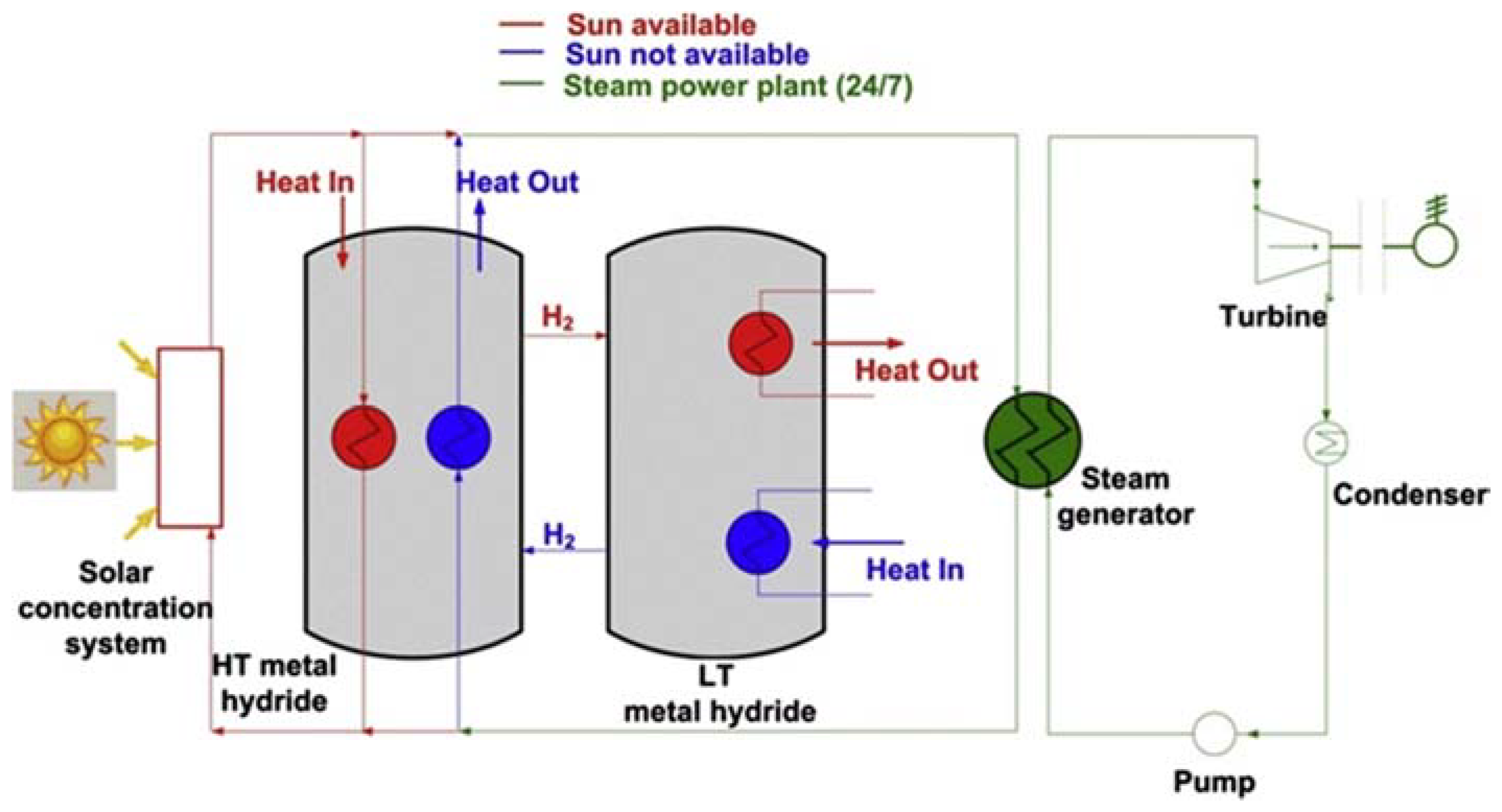
A diagram of a solar thermal energy storage system based on the metal hydrides is illustrated in Figure 1 [4]. It consists of the solar concentration system, the TES system and the power plant, based on the Rankine cycle. There are two kinds of metal hydride materials working at different temperatures. When the solar radiation is strong enough, the heat concentrated by the solar concentration system drives the power plant and produces electricity. Additionally, the extra heat is absorbed by the high temperature metal hydride and stored in the TES system. During the process of extra heat storage, hydrogen is released into the low temperature metal hydride bed and low temperature heat is released. When the sunlight is not available, the low temperature metal hydride is heated and then hydrogen is liberated into high temperature metal hydride bed. The liberated hydrogen reacts with the materials in the high temperature metal hydride bed and provides high temperature heat to the power plant system. As a result, continuous and stable power output could be realized with the function of TES system by storing and releasing thermal energy. Similarly, an innovation based on metal hydride for efficient thermal energy was developed from Pacific Northwest National Laboratory (PNNL) [33]. In their project, the key findings were concluded as follows. The temperature for power generation was 650 °C, charging time was less than 6 h and volumetric energy density for the whole system was 200 kWh/m3. Importantly, compared to the state-of-the-art molten salts, the energy density was increased by 10 times. Additionally, the operating pressure was as low as 1 bar H2 pressure and performed well in the cycle life tests (60 cycles were accomplished).
Among large quantities of metal hydrides, Mg-based materials are pretty suitable for the heat storage application. In the hydrogen storage area, Mg-based materials are promising candidates due to the large abundant reserve in the crust, the light weight of Mg element, and high hydrogen storage capacity (7.6 wt % for Mg) [34,35,36]. However, the relatively higher hydrogen desorption enthalpy (74.6 kJ/mol, from Sandia National Lab database) becomes a restriction for the future application of Mg-based materials for hydrogen storage [35,37,38]. The story is totally different when Mg-based materials are applied to TES. The high hydrogen desorption enthalpy and high hydrogen storage capacity result in a large amount of heat release when the chemical reaction happens at a temperature range from 300 °C to 500 °C under a certain hydrogen pressure (1 to 100 bar) [19,22]. Alefeld et al. [24] first proposed that Mg/MgH2 was a potential system for heat storage application due to its favorable thermodynamic properties and many Mg-based materials were employed as TES materials [22,39,40,41,42,43,44]. Moreover, the theoretical simulation methods were also adopted to effectively investigate the thermal storage properties of Mg-based materials [42,45,46]. In the following context, different Mg-based materials related to energy density, operating temperature, thermodynamics, cycle stability, etc. will be summarized from the viewpoint of TES application.
3.1. Different Heat Storage Systems of Mg-Based Materials
3.1.1. Mg/MgH2 System
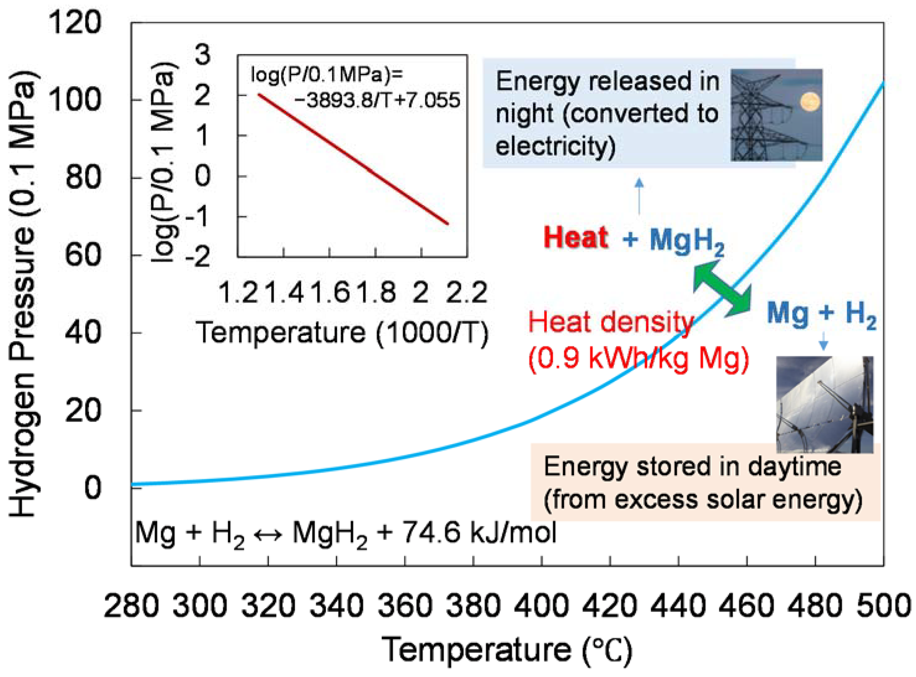
Theoretically, the pure Mg/MgH2 system could possess a thermal energy density as high as 2814 kJ/kg [41]. Compared with one of the largest solar thermal power plants in Granada, Spain, which contains about 28,000 tons of 60% NaNO3 + 40% KNO3 to store concentrated thermal energy, while only 1100 tons of Mg metal will be enough to the same size of heat storage [19]. The particle size of Mg should be controlled in the range of 25–100 µm in order to complete a full conversion to MgH2 and get a faster reaction kinetics at a minimum temperature of 350 °C under normal pressure [41]. With the temperature increases, the Mg metal particles are going to agglomerate and fuse with each other after a certain cycle time, resulting in bad reaction kinetics and an incomplete reaction between Mg particles and hydrogen. It is noted that the high vapor pressure (0.133 bar at 500 °C) of Mg particles and comparatively low melting point (Tm = 650 °C) lead to the poor cycle stability [41]. Indeed, it is of fundamental significance to know the function of H2 dissociation equilibrium pressure against operation temperature for the better controlling of the Mg/MgH2 heat storage system. Figure 2 indicates the clear relationship between hydrogen dissociation pressure and temperature. At a given hydrogen pressure, we could get the lowest temperature for H2 liberation and the highest temperature for the heat release. In other words, based on Figure 2, the direction of the chemical reaction could be adjusted by altering the H2 pressure. On the other hand, it is also feasible to adjust the temperature range to regulate the progress of the irreversible chemical reaction under a certain H2 pressure.
The poor cycling stability of Mg/MgH2 above 400 °C could not meet the requirements in practical application due to the sintering of Mg particles and the high hydrogen equilibrium pressure of MgH2 at high temperature. According to this, many studies were developed and focused on increasing the operation temperature of the Mg/MgH2 system [47,48,49]. Tortoza et al. synthesized a series of Mg (HxF1−x)2 (x = 1, 0.95, 0.85, 0.70, 0.50, 0) compounds by ball milling and annealing under hydrogen atmosphere [50]. They adopted the partial fluoride substitution for hydrogen to tune the thermodynamic properties. As the F content increased, the thermal stability increased while the hydrogen absorption/desorption kinetics decreased. The thermal analysis results presented the maximum rate of H2 desorption at 434 °C with Mg (H0.85F0.15)2. Moreover, the pressure–composition–isothermal (PCI) results of Mg (H0.85F0.15)2 showed the enthalpy (∆Hdes) of 73.6 ± 0.2 kJ/mol H2 and entropy (∆Sdes) of 131.2 ± 0.2 J/k/mol H2 with a hydrogen capacity of 4.6 ± 0.2 wt % H2, which were slightly lower than those of pure MgH2. In addition, the cycle performance investigated at the temperature range from 420 to 480 °C over six cycles showed the increasing thermal operating temperature for TES.
3.1.2. Doped Mg/MgH2 System
To accelerate the chemical reaction, the introduction of catalysts is always a good choice besides increasing reaction temperature and considering the size effect of reaction particles. Ni was used for catalyzing the Mg/MgH2 system by means of doping in hydrogen storage area. Bogdanović et al. [51] developed a wet chemical method to fabricate a good dispersion of Ni-doped Mg particles. The Ni particles were distributed on the surface of Mg particles (2 wt % Ni) and served as a catalyst for hydrogen absorption and desorption [22,51]. The Ni and Mg were also ball-milled to get the Ni-doped Mg particles [52]. According to the result, the powder-method need 5 wt % Ni compared to 2 wt % Ni with the chemical method for the realization of the same catalytic efficiency. After around 200 cycles of hydrogen absorption and desorption, the Mg materials remained active and maintained stable. Moreover, the sample still showed a hydrogen capacity of about 6 wt % after 1000 cycles with respect to the long-term test. Yu et al. [53] reported a facile and simple method to synthesize porous Ni nanofibers by a single-nozzle electrospinning technique. Results showed that the as-synthesized Ni nanofibers showed enhanced catalytic effects on the dehydrogenation performance of MgH2, with the rapid release of 7.02 wt % hydrogen in 11 min at 325 °C. They also obtained an activation energy of 81.5 kJ/mol for the as-milled MgH2–4% Ni nanofibers composite, demonstrating the enhanced kinetics. In addition, they found that the dehydrogenation temperature of MgH2 significantly decreased when amounts of Ni catalyst increased. i.e., from 340 °C for pure MgH2, to 170 °C for the MgH2–2% Ni nanofibers composite, to the lowest value of 143 °C for the MgH2–4% Ni nanofibers sample. The Carnot principle indicates that the higher the heat temperature level, the higher the heat engine’s efficiency. In specific, the steam with a higher temperature is more efficient than that with a lower temperature. However, under the high temperature test, both the two systems (chemical method and powder method) had hydrogen capacity loss as the temperature was higher than 440 °C, which stemmed from the sintering of Mg particles at a temperature higher than 450 °C [19]. The Max Planck Institute designed and built a prototype of a steam generator. 14.5 kg Ni-doped Mg powder was filled into the isolated cylindrical steel pressure vessel and it could be able to generate 6 kg water vapor per hour at the maximum output power of 4 kW. With a total weight of 40 kg, it could reach the maximum operational steam pressure to 50 bar and temperature to 450 °C [19].
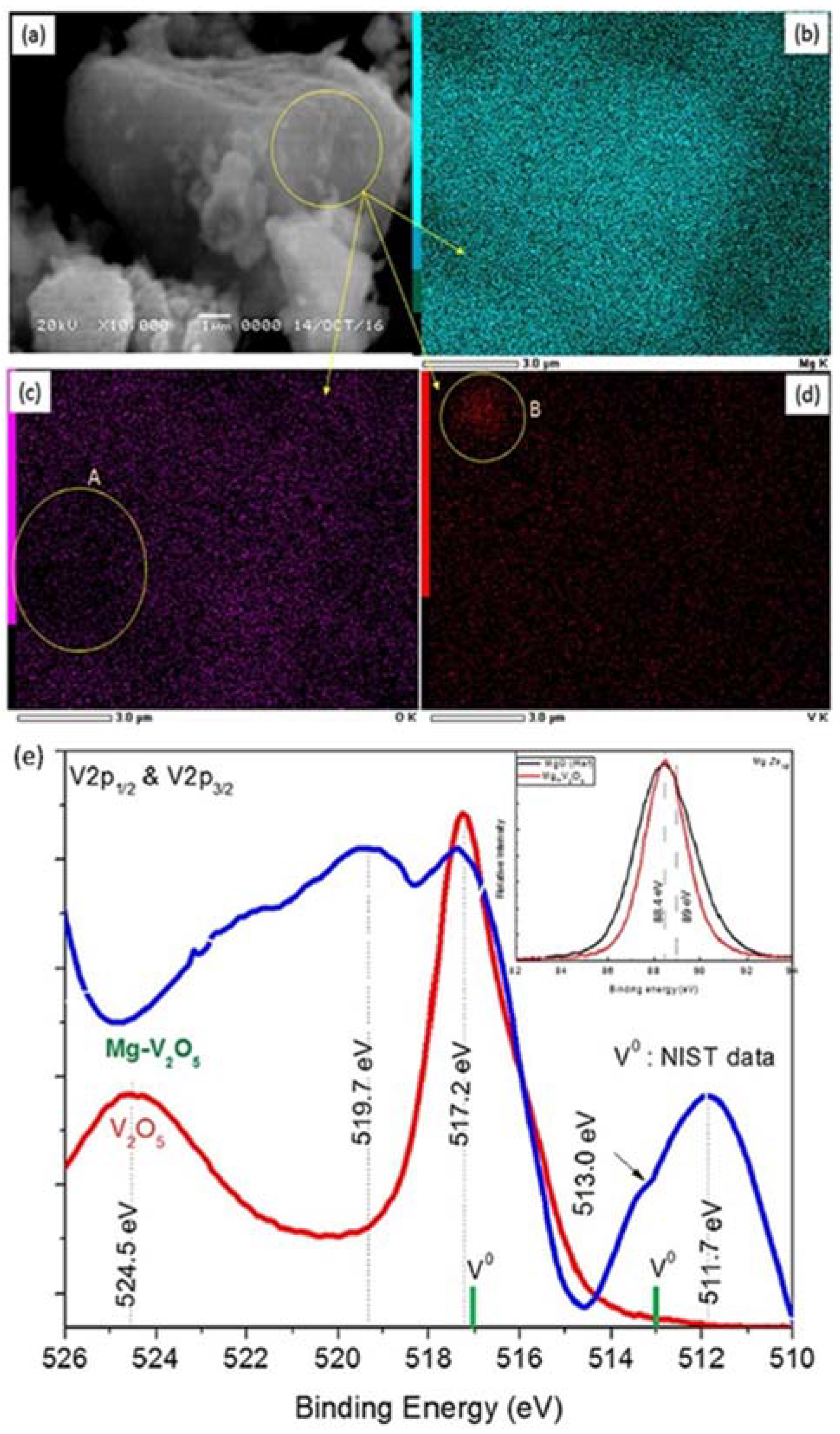
Besides the Ni catalyst, Nb2O5 was also used for catalyzing the hydrogenation/dehydrogenation reaction and improving reaction kinetics [54]. Recently, Kumar et al. [55] reported that the mesoporous amorphous Nb2O5 (mNb2O5) showed remarkable catalytic property on the Mg/MgH2 system. They ball-milled the mixture of commercial mNb2O5 and MgH2 to prepare the mNb2O5-doped MgH2 composite. Compared with crystalline Nb2O5 (cNb2O5), the mNb2O5 presented a smaller particle size and a multiple wavy structure, which provided a large specific surface area for the interaction with MgH2. While the spherical and large particle size of cNb2O5 led to less surface area for the interaction with MgH2. As a result, the mNb2O5 could remarkably reduce the activation energy of hydrogen dissociation process and be able to increase the temperature up to 175 °C within a minute during the hydrogenation process. This intensified heat release coupled with a concentrated solar panel had a promising application for a TES system. Besides the Nb2O5, Kumar and collaborators also fabricated V-doped Mg by dehydrogenation sample obtained from ball milling the mixture of 1 g MgH2 and 5 wt % V2O5 [56]. The XPS analysis (Figure 3e) determined the presence of MgO and V. SEM-EDS results (Figure 3a–d) revealed that vanadium was distributed over the surface of Mg particle. In addition, the uneven area (circled) in the mapping results could be due to the incomplete reduction of V2O5 in that area during ball milling. From the inset curves of Figure 3e, we could see that the peak of Mg2s1/2 was exactly consistent with the Mg2s1/2 peak position of MgO at 88.4 eV. Moreover, the peaks located in 517.2 eV and 513.0 eV referred to V0, the shift of V peak might be due to chemical interaction and the doping of V over Mg surface. Importantly, the thermodynamic calculation found that V2O5 could be reduced by MgH2, producing MgO, metallic V, and hydrogen even at room temperature. This as-prepared sample could rise in temperature up to 192.5 °C within 40 s and showed ultrafast hydrogenation kinetics and remarkably enhanced dehydrogenation kinetics.
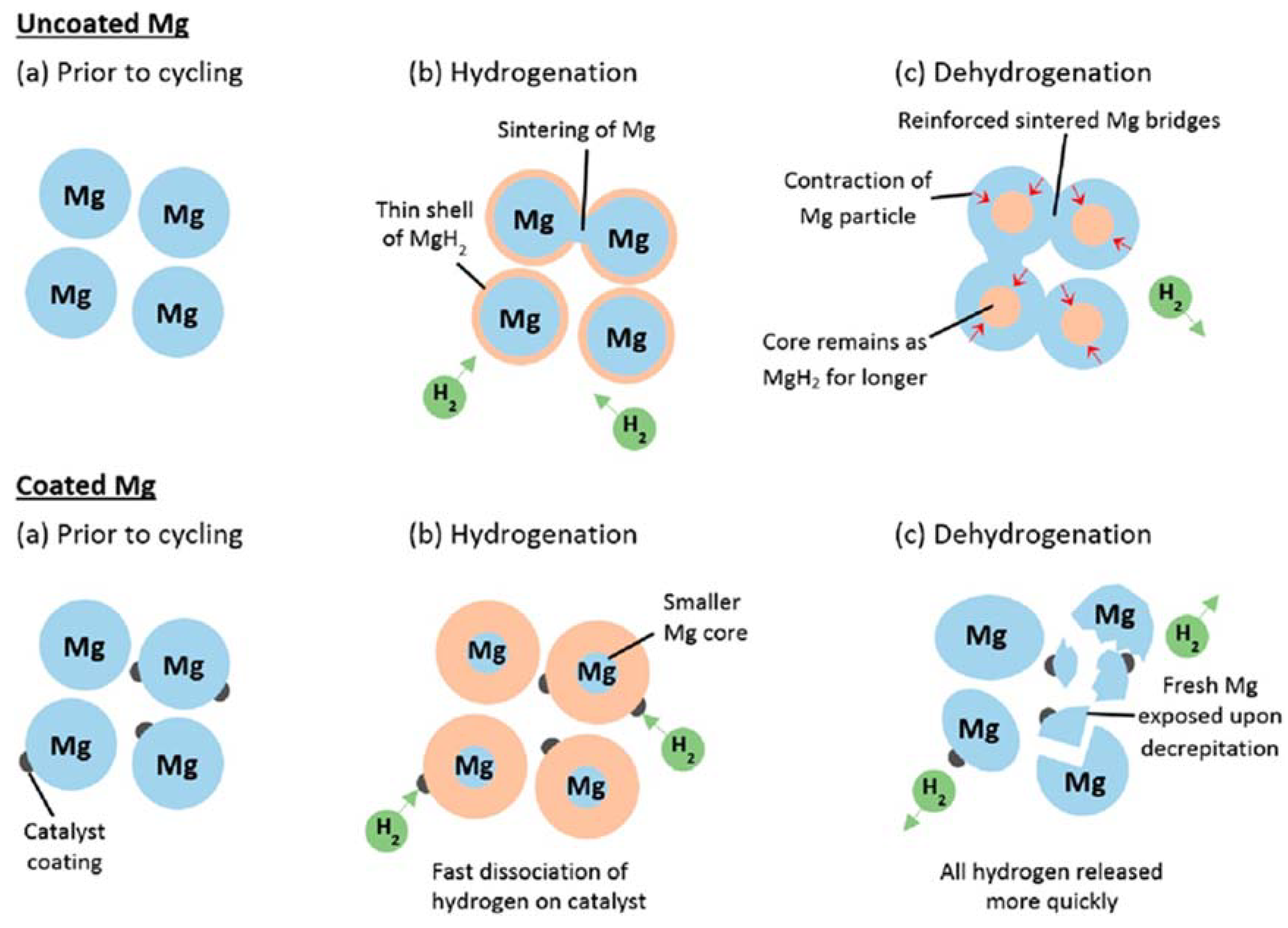
Grant D et al. performed elevated temperature cycling studies on commercial gas atomized Mg powder with various catalysts (chromium, iron, vanadium, and stainless steel) prepared by magnetron sputter method [57]. At 350 °C, the faster reaction kinetics and successive cycling up to 90 times were obtained due to the presence of surface catalysts that boosted the fast nucleation stage of hydrogenation/dehydrogenation. The authors proposed suggested mechanisms for the uncoated Mg and coated Mg samples for hydrogenation/dehydrogenation (Figure 4). They mentioned that particle sintering competed with particle fragmentation during cycling at 350 °C. The coated Mg sample possessed rapid hydrogen diffusion during hydrogenation and quick hydrogen dissociation during dehydrogenation, which was due to the existence of catalysts. The enhancement of hydrogenation kinetics might be attributed to the presence of the catalyst, which increased density of nucleation sites and prevented the sintering phenomena between the Mg particles and the decrepitation of particles during cycling, enabling the catalysts to combine with freshly exposed Mg surface. The mechanism they proposed is beneficial to the detrimental effects on activation and kinetics aspects, which provides a route to develop the TES material with fast kinetics.
3.1.3. The Mg-Fe/Mg2FeH6 System
Mg2FeH6 is one of the suitable materials for high temperature TES system. Yvon et al. [58] firstly discovered Mg2FeH6 in 1984 by heating the mixture of Mg and Fe powders with an atomic ratio of 2:1 under H2 atmosphere. Later, Mg2FeH6 could be prepared by reactive mechanical alloying of Mg and Fe metal powders under the hydrogen atmosphere at room temperature [59,60,61]. Compared with MgH2, as a heat storage material, Mg2FeH6 exhibited much higher stability at high temperatures and lower hydrogen dissociation pressure. With the cycle number increasing, the MgH2 system was going to have a hydrogen capacity loss while the Mg2FeH6 system showed a steady trend of good maintenance. Moreover, Mg2FeH6 system even retained about 5 wt % hydrogen capacity after 600 cycles and presented the heat storage density of ~1921 kJ/kg with a reaction enthalpy about 77 kJ/mol. Since the good cycle stability of Mg2FeH6, they added Mg2FeH6 into the Mg/MgH2 system to inhibit capacity degradation by co-cyclization. The authors even investigated different ratios of Mg: Fe in the mixed Mg2FeH6-MgH2 systems and drew a conclusion that the ratios should lie in less than 20:1 for a good hydrogen capacity cycle stability [62]. They indicated that the possible reason for the good cycle stability of Mg2FeH6 was the separation of metals in two immiscible phases on hydrogen desorption and merging to a compound upon hydrogen absorption [19]. It required a desorption temperature higher than 450 °C due to the outstanding stability at high temperature conditions and even when the temperature was up to 590 °C, the hydrogen desorption cycle stability was not affected.
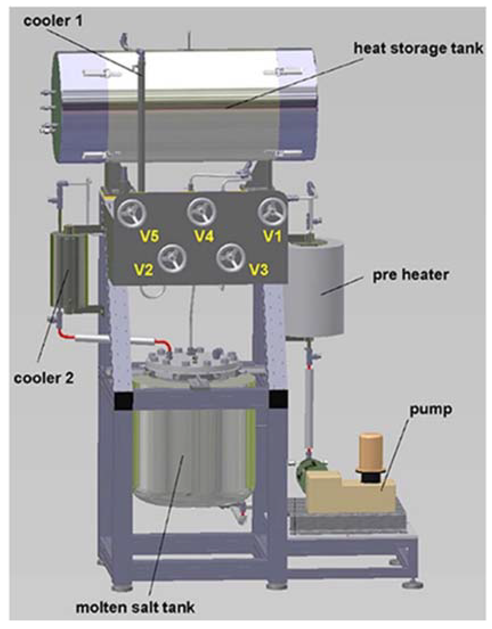
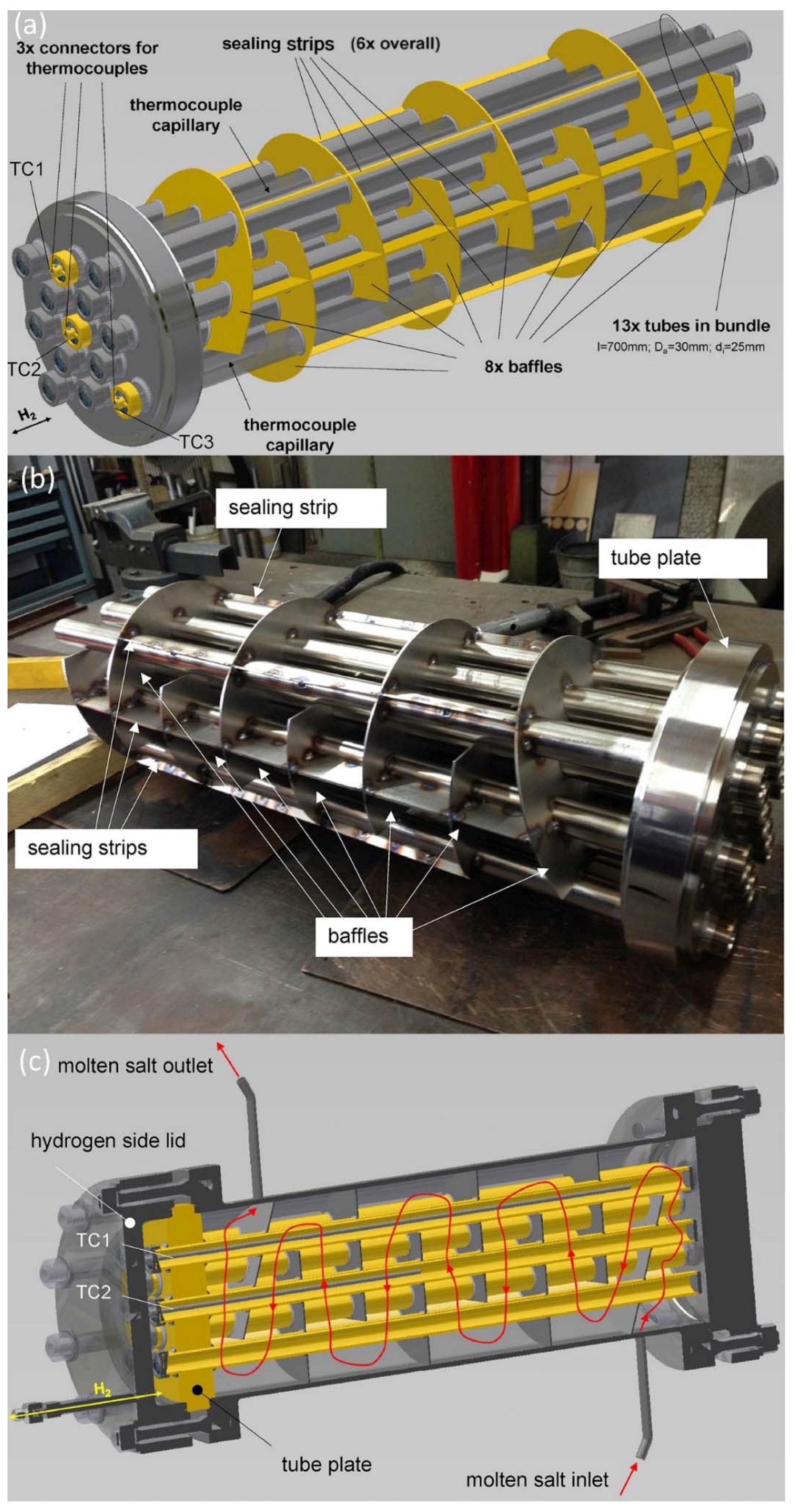
A test rig was designed and assembled recently in Max Planck Institute [63] (Figure 5). The most significant part of this heat storage test rig was the heat storage reactor, which was mainly made up of 13-tube bundle reactor (Figure 6a). Figure 6b shows the tube bundle reactor without the shell. Molten salt was used as heat transfer during heat storage and heat collection. Moreover, it surrounded tubes and flowed as Figure 6c present due to the design of eight baffles. Sealing strips were used to prevent the stream from by-pass at the inner wall of the reactor shell. In this TES system demonstration, 5 kg Mg2FeH6 was filled in the heat storage tank and molten salt served as heat transport medium due to the high working temperature (higher than 400 °C). This test rig demonstration could release 1.6 kWh and store 1.5 kWh heat in the first test. The system did not maintain a stable operating condition during repeated experiments and further improvements of this system were under investigation [63].
3.1.4. The Mg-Co-H System
Mg-Co-H were studied for heat storage material by different researchers with various thermodynamics data reported [64,65,66,67,68]. Yvon et al. [64] reported a value of 86 kJ/mol H2 upon the hydrogen dissociation and 60 kJ/mol H2 for the hydrogen absorption for the Mg2CoH5 phase. Lower values were published by Konstanchuk’s group. [66]. During the experiment process, they found two Mg-Co-H phases after a series of hydrogen desorption measurements and delivered 70 kJ/mol H2 for Mg6Co2H11 and 79 kJ/mol H2 for Mg2CoH5 to the heat of formation. In Shao et al.’s work [67], they successfully fabricated nanostructured Mg2CoH5 and Mg3CoH5 by hydrogen plasma metal reaction and gave the formation enthalpy values of 82.27 kJ/mol H2 and 73.16 kJ/mol H2, respectively. Nevertheless, according to researchers’ experimental results, it is obvious that the Mg-Co-H system has large hydrogen absorption enthalpy to become a suitable chemical heat storage candidate. The sample was prepared with a mixture of Mg and Co powder with a ratio of 2:1 to test cyclic stability and showed a more than 3.1 wt % hydrogen capacity after 1000 cycles. In addition, the experimental results of energy density are about 1472 kJ/kg for Mg6Co2H11 and 1260 kJ/kg for Mg2CoH5 in a temperature range of 450–550 °C [41].
3.1.5. The NaMgH3 System
NaMgH3 is a perovskite-type hydride and which could decompose via a two-step process [69]
NaMgH3 → NaH + Mg + H2 (4.0 wt % H2)
NaH + Mg → Na(l) + Mg + ½H2 (2.0 wt % H2)
Theoretically, there is 6.0 wt % H2 release in total in the two reactions. As a result, NaMgH3 has been considered as a potential hydrogen storage material in recent years. On the other hand, it demonstrated a high thermal stability, a lower hydrogen dissociation pressure, and comparatively low price, which urged this material to be a promising candidate for TES. NaMgH3 was prepared by milling NaH and MgH2 in a 1:1 molar ratio performed cryogenically (77 K) with subsequent annealing under 50 bar of H2 atmosphere at 300 °C [70].
Researchers are always willing to investigate the thermodynamic properties of materials, especially in the area of hydrogen storage and thermal energy storage. There are several publications [70,71,72,73,74] which studied the enthalpy of NaMgH3 for the first decomposition step with the method of pressure-composition-isotherms (PCI). Among them, Ikeda et al. [71] gave an enthalpy value of 93.9 kJ/mol firstly, Komiya et al. [72] reported a close value of 94 kJ/mol and Pottmailer et al. [74] also gave a similar enthalpy value of 92 kJ/mol. Differently, Drew et al. [70] reported a value of 86.6 ± 1.0 kJ/mol in their work. In Drew et al.’s work [70], hydrogen desorption PCI curves for NaMgH3 → NaH + Mg + H2 (Figure 7a) at different temperatures showed 3.29 wt % hydrogen storage capacity experimentally at 398.3 °C. In the subsequent high-temperature measurements, the hydrogen capacity slightly decreased due to the possibly incomplete rehydrogenation. Point A in Figure 7a,b was the equilibrium state of full desorption and the kinetics was slowed down when approached this equilibrium state such that more than 3 h was needed to reach that at the temperature of 418.8 °C. From the van’t Hoff plots (Figure 7c), they calculated the desorption enthalpy for the first step’s decomposition and showed a slightly lower value of 86.6 ± 1.0 kJ/mol H2 at 418.6 °C. They also measured the absorption kinetics after the sample was fully decomposed to Na (l) and Mg. They found that the absorption kinetics were remarkably slowed down after 75% rehydrogenation. However, the absorption kinetics did not start to decrease to 90% rehydrogenation during measuring the hydrogen absorption performance of NaH and Mg. It was probably some problems related to agglomeration of liquid Na metal which led to the slow kinetics in overall decomposition case [74]. A potential solution was utilization of the first step of decomposition to minimize the kinetic and capacity degradation. What is more, the hydrogen dissociation pressure of NaMgH3 was favorable for the thermal energy storage (11 bar at 500 °C) compared to the higher hydrogen dissociation pressure at a high temperature in Mg/MgH2 (92 bar at 500 °C) and Mg2FeH6 (66 bar at 500 °C) systems. Overall, the high enthalpy, low dissociation pressure at high temperature and the wide, flat plateau make NaMgH3 as suitable TES material.
Besides what has been mentioned above, there are a number of other Mg-based materials aiming at the application for TES. Mg2NiH4 has a reaction enthalpy change of ~63 kJ/mol [3,75] but it performs unstable compared to MgH2. Results present that the Mg2NiH4 uptakes the hydrogen capacity of ~3 wt % and shows an lower energy density of 916 kJ/kg than the theoretical value of 1117 kJ/kg because of low formation enthalpy and the heavy weight of materials [41]. Sekhar et al. [76] investigated the performance of Mg + 30% MmNi4 based heat storage system under different hydrogen pressure (10–30 bar) and adsorption temperature (120–150 °C). The maximum value of heat storage was ~714 kJ/kg under the conditions of absorption temperature at 150 °C and supplying hydrogen pressure of 20 bar. Recently, the waste Mg-Al based alloys were used as the starting materials for producing a high quality hydrogen storage system by industrial mills [77]. The as-prepared samples showed good hydrogen sorption capacity (~6 wt %) and fast hydrogenation kinetics, which were promising to apply for TES.
3.2. Kinetics and Thermal Conductivity Properties
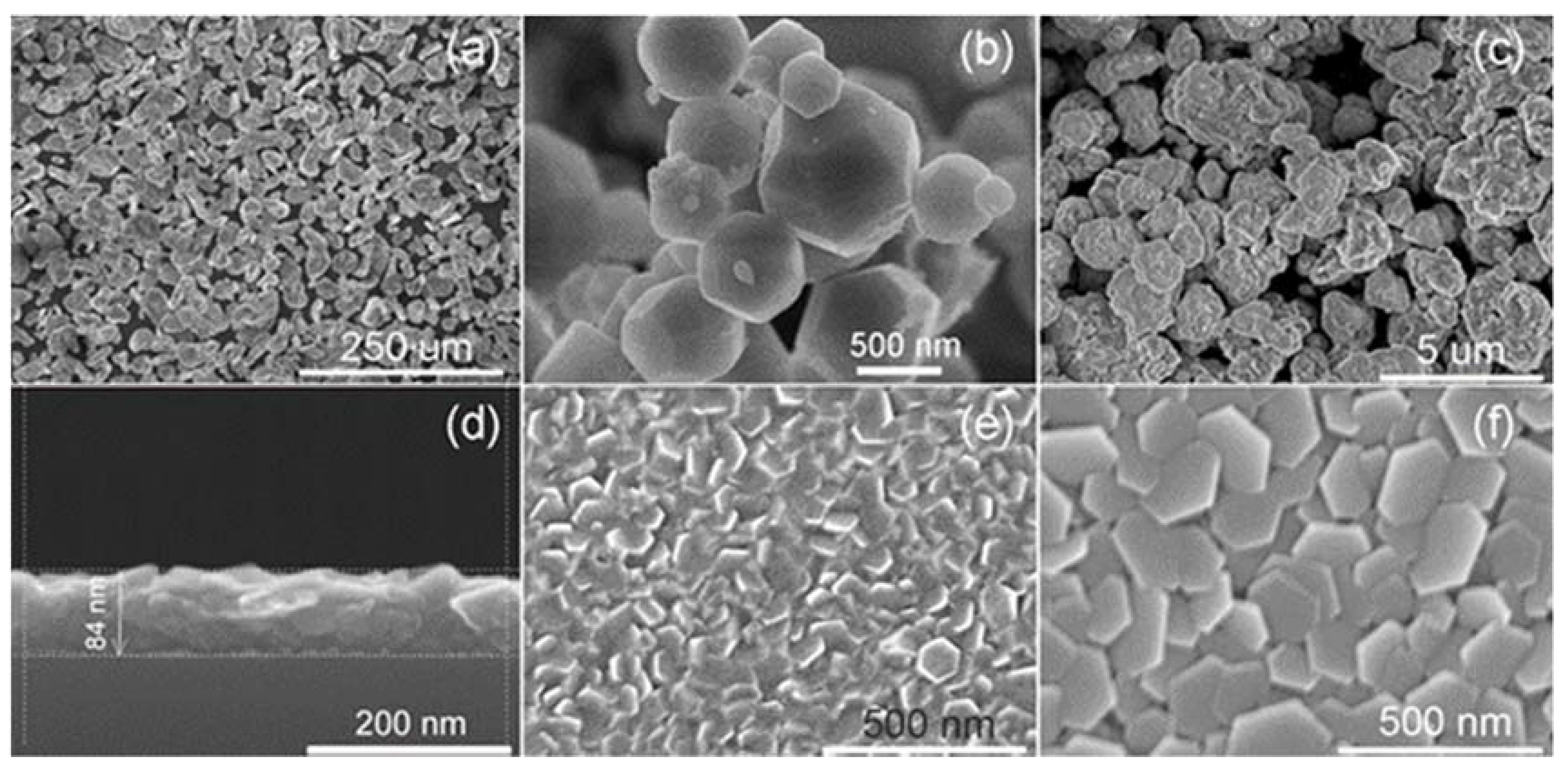
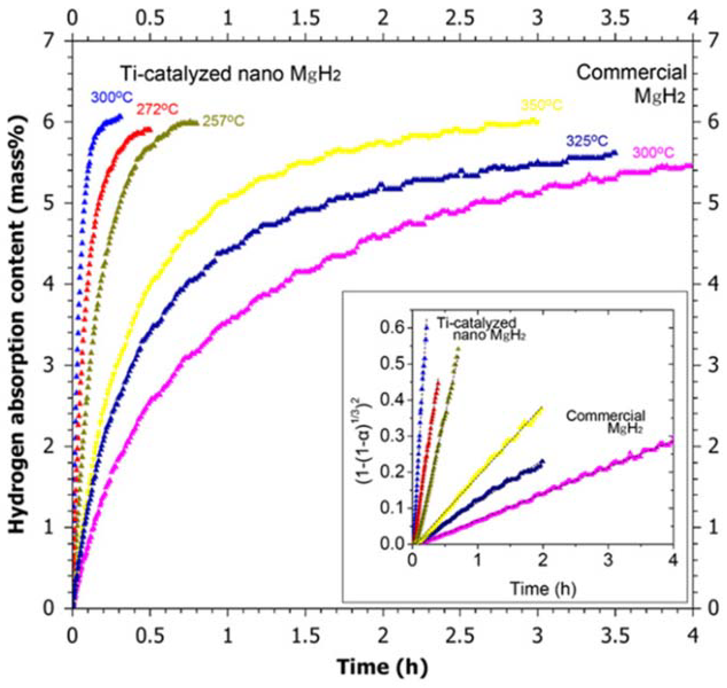
For a specific chemical reaction applied for TES, the progress of the chemical reaction is much faster than the rate of thermal conductivity, as a result, the rate-limiting step of this chemical heat storage system is the rate of thermal conductivity [19]. Besides the heat transfer ability of the storage tank and internal heat exchanger, the most significant issue is the thermal conductivity of materials. In PNNL’s project [33], they used open cell Duocel copper foam with interstitial spaces, which was filled with metal hydride powder to enhance thermal conductivity in both radial and axial directions. Shao et al. [78] studied and summarized different types of Mg-based materials with various structures (Figure 8) and evaluated their thermal and kinetics properties (Table 4). In their work, samples such as micrometer scale Mg powders, Mg nanoparticles, single crystal Mg, nanocrystalline Mg50Co50 body centered cubic (bcc) alloy, and Mg thin film were investigated. Due to the much more scattering of electron/phonon by more boundaries in nanostructured materials, the Mg nanoparticles and Mg50Co50 alloy delivered poor thermal conductivity and relatively low heat capacity. However, compared with other microscale materials (325 mesh Mg, Mg single crystal), the nanostructured materials showed an outstanding hydrogen absorption kinetics. On the one hand, nanoscale materials could optimize the hydrogen absorption kinetics. On the other hand, it would sacrifice the thermal conductivity. A similar phenomenon was observed between the Ti-catalyzed nanoscale MgH2 and commercial MgH2 (Figure 9) [34], Ti-catalyzed nanoscale MgH2 performed much faster hydrogen absorption kinetics than commercial MgH2 under the same conditions. The inset of Figure 9 also suggested the huge difference in hydrogen absorption rate based on the simulation of Jander diffusion Equation [79]. Also, Toberer et al. [80] found the thermal conductivity decreased with the increasing of critical thickness in silicones with different morphologies (film, nanocrystalline, nanowire) at 300 K.
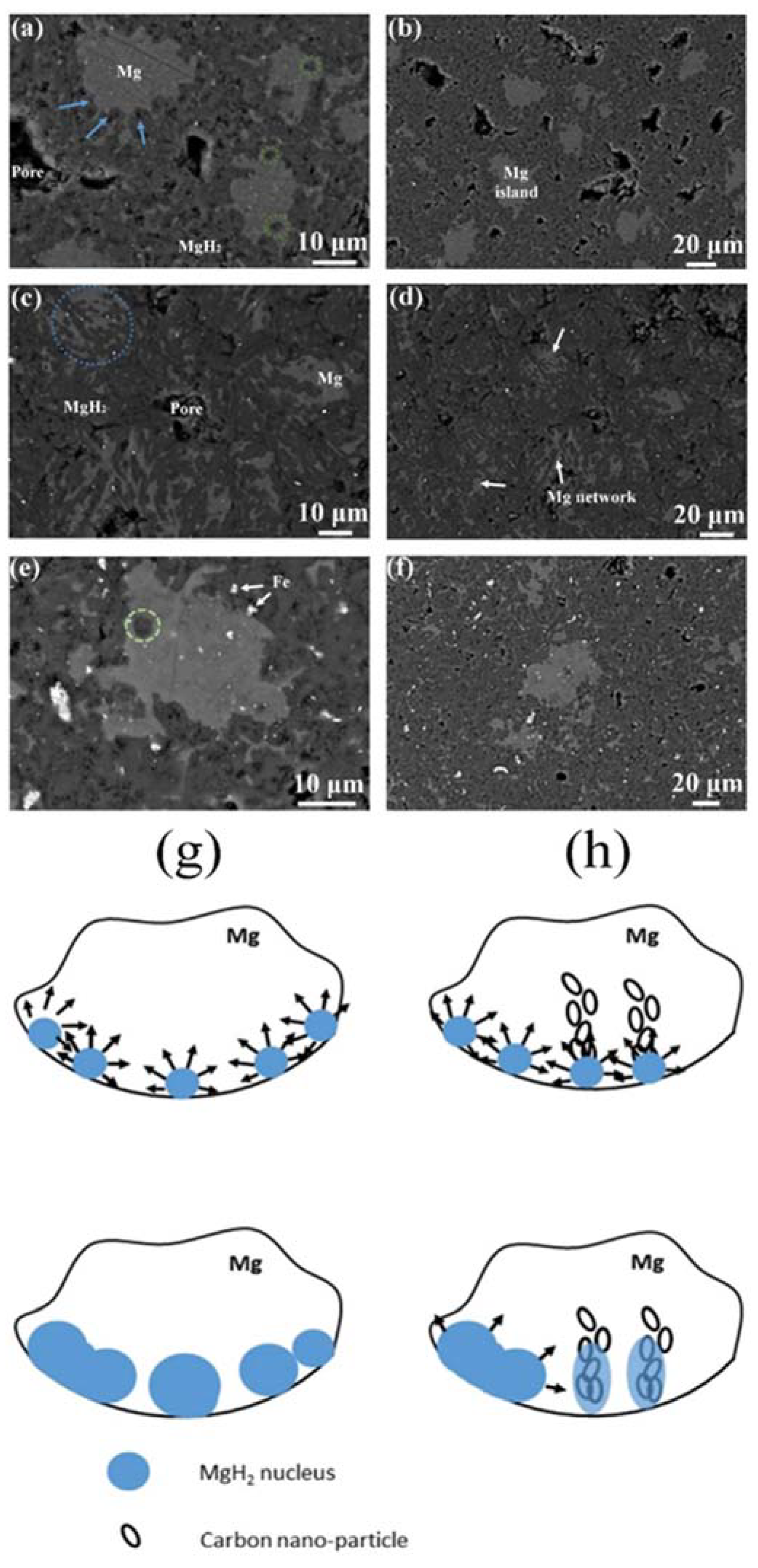
However, it seems that Rabkin et al. recently have found a solution [81]. They prepared the solid porous pellets of Mg-2 wt % multiwall carbon nanotubes (MWCNTs) composites, which were fabricated by high energy ball milling of Mg powder with MWCNTs additives, followed by uniaxial compression and sintering in hydrogen atmosphere under mechanical constraint. From the BSE micrographs of the as-prepared partially hydrogenated samples (Figure 10), we could see that Mg pellets without additive presented nearly circular interconnected MgH2 (circles marked) and isolated Mg islands (Figure 10a,b). While the pellets with MWCNTs additives showed elongated MgH2 nuclei (marked by the circle) and interconnected network of metallic Mg (Figure 10c,d). The Figure 10e,f were the morphologies of control pellet using 2 wt % Fe as additive to exclude effect to the growing hydride phase from iron-rich precipitates. The overall microstructure (Figure 10e,f) looked similar to the pure Mg pellets, which indicated that the special morphology observed in the Mg-2 wt % MWCNTs composites was related to the carbon nanotubes. The asymmetrical and anisotropic MgH2 nuclei indicated that the growth of MgH2 was much faster along the carbon-rich direction and which means hydrogen diffused much faster along the Mg-carbon interfaces. The proposed mechanism clearly presented us the different MgH2 nucleus grow process in the Mg-2 wt % MWCNTs sample (Figure 10h) compared to the pure Mg one (Figure 10g). Such anisotropic microstructure had a tendency to solve the incompatibilty problem between thermal conductivity and kinetics. Firstly, the interconnected metallic Mg network enabled the rapid heat transfer over a large distance, which resulted in improved thermal conductivity. According to their results, the thermal conductivity of the pellets with Mg-2 wt % MWCNTs was improved by over 20% than the pure Mg one. Secondly, hydrogen could diffuse more deeply into the particle due to the interconnected metallic Mg network, which ensured the fast hydrogenation kinetics. Yu et al. [82] also developed a general strategy for facile preparation of monodispersed MgH2 nanoparticles on graphene. Under the structure-directing role of graphene, the as-prepared sample showed high thermal conductivity and good hydrogen storage performance (5.7 wt % H2 capacity for the 75 wt % MgH2 loading percentage). Shim et al. [83] fabricated the cylindrical MgH2 compacts containing up to 20 wt % graphite flakes with an average size of 20–1200 µm by the uniaxial compression at 100 MPa. The dispersed graphite flakes were aligned perpendicularly to the compression direction, which had a great enhancement to the effective thermal conductivity. The measured conductivity almost linearly increased with increasing graphite content and could reach 9.3 W m−1 K−1 at 20 wt % graphite at 1 bar of hydrogen. They also found the hydrogen pressure and the size of graphite flakes influenced the thermal conductivity. Overall, the kinetics performance of the heat storage system heavily depends on hydrogen absorption kinetics and thermal conductivity of the materials. It seems that the nanoengineering and proper nanocomposites could handle and balance the relationship of hydrogen absorption kinetics and thermal conductivity.
Here, we have introduced different TES systems in detail, which include Mg/MgH2, doped Mg/MgH2, Mg-Fe/Mg2FeH6, Mg-Co-H, and NaMgH3 systems. The related properties such as energy density, reaction temperature, cycle stability, kinetics, thermodynamic properties, as well as preparation methods, have been introduced. Other materials such as Mg2NiH4 and Mg + 30% MmNi4 systems are also briefly discussed. The combination of high thermodynamic stability and good hydrogen capacity make Mg-based materials suitable candidates as TES materials and a wide range of temperatures are covered by those different Mg-based heat storage materials. The low dissociation pressure is favorable both in technical and economical aspect and thermal stability is also a significant factor to evaluate a TES material. Materials such as Mg-Fe/Mg2FeH6 and NaMgH3 with good thermal stability and low hydrogen dissociation pressure would attract more attention and go to further investigation. In a certain TES system, the thermal conductivity and heat desorption kinetics of material are also dominant issues for the performance of the TES system. The hydrogen absorption kinetics and thermal conductivity are two conflicting factors and further research should be developed to balance them. In practice, we could enhance thermal conductivity by means of constructing a heat pipe or adding thermal conductive material (such as graphite, copper, etc.). However, it would sacrifice the heat storage density and increase cost due to the extra component. Some studies show that nanosizing technologies are able to remarkably enhance the kinetics of hydrogen absorption and with the help of nanoengineering and nanocomposite technology, we could actually gain fast kinetics as well as high thermal conductivity at the same time.
4. Conclusions and Perspective
Thermal energy from solar radiation is a potential candidate to serve as an energy reserve. Compared with sensible heat and latent heat storage, chemical heat storage demonstrates to be an advantageous technology for TES due to its high energy density in a wide temperature range and long storage duration without heat loss. In recent decades, a great number of scientists devoted themselves to the research of reversible chemical heat storage [1,2,3,15,19,62,84,85]. There were various materials proposed already and fabricated for TES in theoretical and experimental cases. Mg-based materials are known for hydrogen storage area due to the abundant reserves, low cost, high hydrogen capacity, and light weight, but the related thermodynamic problems (high dehydrogenation enthalpy) limit their further application. In the research of TES, the drawback of high reaction enthalpy becomes the core advantage of those materials for Mg-based materials. In the Ni-doped Mg/MgH2 system, which even exhibited an energy density as high as 2147 kJ/kg [41]. Different types of Mg-based materials for thermal storage are reviewed and materials like Mg-Fe/Mg2FeH6 and NaMgH3 with low hydrogen dissociation pressure and good thermal stability are more favorable for TES. Based on the current development of chemical heat storage, the thermodynamic and kinetic properties dominate the heat storage properties of reversible chemical reaction. Different from the thermodynamic problems in hydrogen storage, the high reaction enthalpy and fast reaction kinetics help to improve the efficiency of the TES system and make the reaction release more thermal energy and to do so quickly. Evaluated from energy density, Mg-based materials are suitable for TES. However, the low hydrogen absorption pressure and thermal stability become the limitation. The introduction of different metal hydrides to form a composite might be a good choice. The enhancement of thermal conductivity is necessary to the TES system, how to get a good heat transfer ability on the basis of fast hydrogen absorption kinetics still need further investigation. The additives or catalysts can optimize the kinetics but whether they will maintain stable during numerous cycles at high temperature needs to be confirmed. The design of a proper reactor for the chemical reaction and chemical stability of the reversible reaction also remains challenging.
Author Contributions
H.S. conceived and designed the concept and L.H. designed some of the main ideas for the construction of the paper construction. B.L. and J.L. contributed to the writing.
Funding
H.S. acknowledges the Macau Science and Technology Development Fund (FDCT) for funding (project No. 118/2016/A3 and 0062/2018/A2), and this work was also partially supported by a Start-Up Research Fund from the University of Macau (SRG2016-00088-FST).
Conflicts of Interest
The authors declare no conflict of interest.
References
- Gil, A.; Medrano, M.; Martorell, I.; Lázaro, A.; Dolado, P.; Zalba, B.; Cabeza, L.F. State of the art on high temperature thermal energy storage for power generation. Part 1—Concepts, materials and modellization. Renew. Sustain. Energy Rev. 2010, 14, 31–55. [Google Scholar] [CrossRef]
- Aydin, D.; Casey, S.P.; Riffat, S. The latest advancements on thermochemical heat storage systems. Renew. Sustain. Energy Rev. 2015, 41, 356–367. [Google Scholar] [CrossRef]
- Yan, T.; Wang, R.Z.; Li, T.X.; Wang, L.W.; Fred, I.T. A review of promising candidate reactions for chemical heat storage. Renew. Sustain. Energy Rev. 2015, 43, 13–31. [Google Scholar] [CrossRef]
- Ward, P.A.; Corgnale, C.; Teprovich, J.A.; Motyka, T.; Hardy, B.; Peters, B.; Zidan, R. High performance metal hydride based thermal energy storage systems for concentrating solar power applications. J. Alloys Compd. 2015, 645, S374–S378. [Google Scholar] [CrossRef] [Green Version]
- Qu, X.; Li, Y.; Li, P.; Wan, Q.; Zhai, F. The development of metal hydrides using as concentrating solar thermal storage materials. Front. Mater. Sci. 2015, 9, 317–331. [Google Scholar] [CrossRef]
- Abbott, D. Keeping the energy debate clean: How do we supply the world’s energy needs? Proc. IEEE 2010, 98, 42–66. [Google Scholar] [CrossRef]
- Mendoza, B. Total solar irradiance and climate. Adv. Space Res. 2005, 35, 882–890. [Google Scholar] [CrossRef]
- Hermann, W.A. Quantifying global exergy resources. Energy 2006, 31, 1685–1702. [Google Scholar] [CrossRef]
- Archer, C.L.; Jacobson, M.Z. Evaluation of global wind power. J. Geophys. Res. Atmos. 2005, 110. [Google Scholar] [CrossRef] [Green Version]
- Pollack, H.N.; Hurter, S.J.; Johnson, J.R. Heat flow from the earth’s interior: Analysis of the global data set. Rev. Geophys. 1993, 31, 267–280. [Google Scholar] [CrossRef]
- Milliman, J.; Farnsworth, K. Fluvial Discharge of Silicate to the Oceans: A Global Perspective; School of Marine Science, College of William and Mary: Gloucester Point, VA, USA, 1999. [Google Scholar]
- Panicker, N.N. Power resource estimate of ocean surface waves. Ocean Eng. 1975, 3, 429–439. [Google Scholar] [CrossRef]
- Ray, R.; Eanes, R.; Chao, B. Detection of tidal dissipation in the solid earth by satellite tracking and altimetry. Nature 1996, 381, 595–597. [Google Scholar] [CrossRef]
- Quayle, R.G.; Changery, M.J. Estimates of coastal deepwater wave energy potential for the world. In OCEANS 81; IEEE: Piscataway, NJ, USA, 1982; pp. 903–907. [Google Scholar]
- N’Tsoukpoe, K.E.; Liu, H.; Le Pierrès, N.; Luo, L. A review on long-term sorption solar energy storage. Renew. Sustain. Energy Rev. 2009, 13, 2385–2396. [Google Scholar] [CrossRef]
- Zalba, B.; Marín, J.M.; Cabeza, L.F.; Mehling, H. Review on thermal energy storage with phase change: Materials, heat transfer analysis and applications. Appl. Therm. Eng. 2003, 23, 251–283. [Google Scholar] [CrossRef]
- Møller, K.T.; Sheppard, D.; Ravnsbæk, D.B.; Buckley, C.E.; Akiba, E.; Li, H.W.; Jensen, T.R. Complex metal hydrides for hydrogen, thermal and electrochemical energy storage. Energies 2017, 10, 1645. [Google Scholar] [CrossRef]
- Felderhoff, M.; Urbanczyk, R.; Peil, S. Thermochemical heat storage for high temperature applications—A review. Green 2013, 3, 113–123. [Google Scholar] [CrossRef]
- Felderhoff, M.; Bogdanovic, B. High temperature metal hydrides as heat storage materials for solar and related applications. Int. J. Mol. Sci. 2009, 10, 325–344. [Google Scholar] [CrossRef] [PubMed]
- Sharma, A.; Tyagi, V.V.; Chen, C.R.; Buddhi, D. Review on thermal energy storage with phase change materials and applications. Renew. Sustain. Energy Rev. 2009, 13, 318–345. [Google Scholar] [CrossRef]
- Tian, Y.; Zhao, C.Y. A review of solar collectors and thermal energy storage in solar thermal applications. Appl. Energy 2013, 104, 538–553. [Google Scholar] [CrossRef] [Green Version]
- Bogdanović, B.; Ritter, A.; Spliethoff, B. Active MgH2-Mg systems for reversible chemical energy storage. Angew. Chem. Int. Ed. 1990, 29, 223–234. [Google Scholar] [CrossRef]
- Aochi, A.; Tadokoro, T.; Yoshida, K.; Kameyama, H.; Nobue, M.; Yamaguchi, T. Economical and technical evaluation of ut-3 thermochemical hydrogen production process for an industrial scale plant. Int. J. Hydrogen Energy 1989, 14, 421–429. [Google Scholar] [CrossRef]
- Alefeld, G. Energiespeicherung durch heterogenverdampfung (I). Wärme 1975, 81, 89. [Google Scholar]
- Herrmann, U.; Kearney, D.W. Survey of thermal energy storage for parabolic trough power plants. J. Sol. Energy Eng. 2002, 124, 145–152. [Google Scholar] [CrossRef]
- Reilly, H.; Kolb, G. Evaluation of Molten Salt Power Tower Technology Based on Experience at Solar Two; Report No. SAND2001-3674; Sandia National Laboratories: Albuquerque, New Mexico, 2001. [Google Scholar]
- Kubota, M.; Yokoyama, K.; Watanabe, F.; Hasatani, M. Heat releasing characteristics of CaO/CaCO3 reaction in a packed bed for high temperature heat storage and temperature up-grading. In Proceedings of the 8th International Conference on Thermal Energy Storage (Terrastock 2000), Stuttgart, Germany, 28 August–1 September 2000. [Google Scholar]
- Visscher, K. Solarcombi systems, heading for 100% solar fraction. Presented at the VSK Exhibition, Utrecht, The Netherlands, 2004. [Google Scholar]
- Hahne, E. Thermal energy storage: Some views on some problems. In Proceedings of the 8th International Heat Transfer Conference, San Francisco, CA, USA, 17–22 August 1986; pp. 279–292. [Google Scholar]
- Lovegrove, K.; Luzzi, A.; Kreetz, H. A solar-driven ammonia-based thermochemical energy storage system. Sol. Energy 1999, 67, 309–316. [Google Scholar] [CrossRef]
- Steinfeld, A.; Sanders, S.; Palumbo, R. Design aspects of solar thermochemical engineering—A case study: Two-step water-splitting cycle using the Fe3O4/FeO redox system. Sol. Energy 1999, 65, 43–53. [Google Scholar] [CrossRef]
- Shiizaki, S.; Nagashimga, I.; Iwata, K.; Hosoda, T.; Kameyama, H. Development of plate fin reactor for heat recovery system using methanol decomposition. In Proceedings of the 8th International Conference on Thermal Energy Storage (Terrastock 2000), Stuttgart, Germany, 28 August–1 September 2000. [Google Scholar]
- Rönnebro, E.; Whyatt, G.; Powell, M.; Simmons, K.; Fang, Z.; White, R. Reversible metal hydride thermal energy storage for high temperature power generation systems. In Proceedings of the Concentrating Solar Power Program Review, Phoenix, AZ, USA, 23–25 April 2013; pp. 29–30. [Google Scholar]
- Shao, H.; Xin, G.; Zheng, J.; Li, X.; Akiba, E. Nanotechnology in Mg-based materials for hydrogen storage. Nano Energy 2012, 1, 590–601. [Google Scholar] [CrossRef]
- Shao, H.; He, L.; Lin, H.; Li, H.-W. Progress and trends in magnesium-based materials for energy-storage research: A review. Energy Technol. 2018, 6, 445–458. [Google Scholar] [CrossRef]
- Li, J.; Xu, J.; Li, B.; He, L.; Lin, H.; Li, H.W.; Shao, H. Advanced sem and tem techniques applied in Mg-based hydrogen storage research. Scanning 2018, 2018. [Google Scholar] [CrossRef]
- Shao, H. Heat modeling and material development of Mg-based nanomaterials combined with solid oxide fuel cell for stationary energy storage. Energies 2017, 10, 1767. [Google Scholar] [CrossRef]
- Li, J.; Li, B.; Shao, H.; Li, W.; Lin, H. Catalysis and downsizing in Mg-based hydrogen storage materials. Catalysts 2018, 8, 89. [Google Scholar] [CrossRef]
- Bogdanović, B.; Ritter, A.; Spliethoff, B.; Straβburger, K. A process steam generator based on the high temperature magnesium hydride/magnesium heat storage system. Int. J. Hydrogen Energy 1995, 20, 811–822. [Google Scholar] [CrossRef]
- Bogdanović, B.; Spliethoff, B.; Ritter, A. The magnesium hydride system for heat storage and cooling. Z. Phys. Chem. 1989, 164, 1497–1508. [Google Scholar] [CrossRef]
- Reiser, A.; Bogdanović, B.; Schlichte, K. The application of Mg-based metal-hydrides as heat energy storage systems. Int. J. Hydrogen Energy 2000, 25, 425–430. [Google Scholar] [CrossRef]
- Friedlmeier, G.; Groll, M. Experimental analysis and modelling of the hydriding kinetics of Ni-doped and pure mg. J. Alloys Compd. 1997, 253, 550–555. [Google Scholar] [CrossRef]
- Steiner, D.; Groll, M.; Wierse, M. Development and Investigation of Thermal Energy Storage Systems for the Medium Temperature Range; American Society of Mechanical Engineers: New York, NY, USA, 1995. [Google Scholar]
- Buchner, H.; Povel, R. The daimler-benz hydride vehicle project. Int. J. Hydrogen Energy 1982, 7, 259–266. [Google Scholar] [CrossRef]
- Marty, P.; Fourmigue, J.-F.; De Rango, P.; Fruchart, D.; Charbonnier, J. Numerical simulation of heat and mass transfer during the absorption of hydrogen in a magnesium hydride. Energy Convers. Manag. 2006, 47, 3632–3643. [Google Scholar] [CrossRef]
- Askri, F.; Jemni, A.; Nasrallah, S.B. Study of two-dimensional and dynamic heat and mass transfer in a metal–hydrogen reactor. Int. J. Hydrogen Energy 2003, 28, 537–557. [Google Scholar] [CrossRef]
- Sheppard, D.; Humphries, T.; Buckley, C. What is old is new again. Mater. Today 2015, 18, 415. [Google Scholar] [CrossRef]
- Humphries, T.D.; Sheppard, D.A.; Rowles, M.R.; Sofianos, M.V.; Buckley, C. Fluoride substitution in sodium hydride for thermal energy storage applications. J. Mater. Chem. A 2016, 4, 12170–12178. [Google Scholar] [CrossRef] [Green Version]
- Sheppard, D.; Corgnale, C.; Hardy, B.; Motyka, T.; Zidan, R.; Paskevicius, M.; Buckley, C. Hydriding characteristics of NaMgH2F with preliminary technical and cost evaluation of magnesium-based metal hydride materials for concentrating solar power thermal storage. RSC Adv. 2014, 4, 26552–26562. [Google Scholar] [CrossRef]
- Tortoza, M.S.; Humphries, T.D.; Sheppard, D.A.; Paskevicius, M.; Rowles, M.R.; Sofianos, M.V.; Aguey-Zinsou, K.-F.; Buckley, C.E. Thermodynamics and performance of the Mg-H-F system for thermochemical energy storage applications. Phys. Chem. Chem. Phys. 2018, 20, 2274–2283. [Google Scholar] [CrossRef] [PubMed]
- Bogdanović, B.; Liao, S.T.; Schwickardi, M.; Sikorsky, P.; Spliethoff, B. Katalytische synthese von magnesiumhydrid unter milden bedingungen. Angew. Chem. 1980, 92, 845–846. [Google Scholar] [CrossRef]
- Bogdanović, B.; Hartwig, T.; Spliethoff, B. The development, testing and optimization of energy storage materials based on the MgH2-Mg system. Int. J. Hydrogen Energy 1993, 18, 575–589. [Google Scholar] [CrossRef]
- Chen, J.; Xia, G.; Guo, Z.; Huang, Z.; Liu, H.; Yu, X. Porous Ni nanofibers with enhanced catalytic effect on the hydrogen storage performance of MgH2. J. Mater. Chem. A 2015, 3, 15843–15848. [Google Scholar] [CrossRef]
- Barkhordarian, G.; Klassen, T.; Bormann, R. Fast hydrogen sorption kinetics of nanocrystalline mg using Nb2O5 as catalyst. Scr. Mater. 2003, 49, 213–217. [Google Scholar] [CrossRef]
- Kumar, S.; Kojima, Y.; Dey, G.K. Morphological effects of Nb2O5 on MgH2-Mg system for thermal energy storage application. Int. J. Hydrogen Energy 2018, 43, 809–816. [Google Scholar] [CrossRef]
- Kumar, S.; Kojima, Y.; Kain, V. Nano-engineered MgH2-Mg system for solar thermal energy storage. Sol. Energy 2017, 150, 532–537. [Google Scholar] [CrossRef]
- Mistry, P.C.; Grant, D.M.; Stuart, A.D.; Manickam, K.; Walker, G.S. Evolution of catalyst coated atomised magnesium spheres—An alternative thermal storage medium for concentrated solar power applications. Int. J. Hydrogen Energy 2017, 42, 28453–28463. [Google Scholar] [CrossRef]
- Didisheim, J.; Zolliker, P.; Yvon, K.; Fischer, P.; Schefer, J.; Gubelmann, M.; Williams, A. Dimagnesium iron (II) hydride, MgH2FeH6, containing octahedral FeH64− anions. Inorg. Chem. 1984, 23, 1953–1957. [Google Scholar] [CrossRef]
- Huot, J.; Boily, S.; Akiba, E.; Schulz, R. Direct synthesis of Mg 2 FeH 6 by mechanical alloying. J. Alloys Compd. 1998, 280, 306–309. [Google Scholar] [CrossRef]
- Gennari, F.; Castro, F.; Gamboa, J.A. Synthesis of MgH2FeH6 by reactive mechanical alloying: Formation and decomposition properties. J. Alloys Compd. 2002, 339, 261–267. [Google Scholar] [CrossRef]
- Varin, R.; Li, S.; Calka, A.; Wexler, D. Formation and environmental stability of nanocrystalline and amorphous hydrides in the 2Mg–Fe mixture processed by controlled reactive mechanical alloying (CRMA). J. Alloys Compd. 2004, 373, 270–286. [Google Scholar] [CrossRef]
- Bogdanović, B.; Reiser, A.; Schlichte, K.; Spliethoff, B.; Tesche, B. Thermodynamics and dynamics of the Mg–Fe–H system and its potential for thermochemical thermal energy storage. J. Alloy. Compd. 2002, 345, 77–89. [Google Scholar] [CrossRef]
- Urbanczyk, R.; Peinecke, K.; Peil, S.; Felderhoff, M. Development of a heat storage demonstration unit on the basis of MgH2FeH6 as heat storage material and molten salt as heat transfer media. Int. J. Hydrogen Energy 2017, 42, 13818–13826. [Google Scholar] [CrossRef]
- Zolliker, P.; Yvon, K.; Fischer, P.; Schefer, J. Dimagnesium cobalt (I) pentahydride, Mg2CoH5, containing square-pyramidal pentahydrocobaltate (4−)(CoH54−) anions. Inorg. Chem. 1985, 24, 4177–4180. [Google Scholar] [CrossRef]
- Černý, R.; Bonhomme, F.; Yvon, K.; Fischer, P.; Zolliker, P.; Cox, D.; Hewat, A. Hexamagnesium dicobalt undecadeuteride Mg6Co2D11: Containing [CoD4]5− and [CoD5]4− complex anions conforming to the 18-electron rule. J. Alloys Compd. 1992, 187, 233–241. [Google Scholar] [CrossRef]
- Ivanov, E.Y.; Konstanchuk, I.; Stepanov, A.; Jie, Y.; Pezat, M.; Darriet, B. The ternary system magnesium-cobalt-hydrogen. Inorg. Chem. 1989, 28, 613–615. [Google Scholar] [CrossRef]
- Shao, H.; Xu, H.; Wang, Y.; Li, X. Synthesis and hydrogen storage behavior of Mg–Co–H system at nanometer scale. J. Solid State Chem. 2004, 177, 3626–3632. [Google Scholar] [CrossRef]
- Yoshida, M.; Bonhomme, F.; Yvon, K.; Fischer, P. On the composition and structure of the cubic δ-phase in the Mg–Co–H system. J. Alloys Compd. 1993, 190, 45–46. [Google Scholar] [CrossRef]
- Wu, H.; Zhou, W.; Udovic, T.J.; Rush, J.J.; Yildirim, T. Crystal chemistry of perovskite-type hydride NaMgH3: Implications for hydrogen storage. Chem. Mater. 2008, 20, 2335–2342. [Google Scholar] [CrossRef]
- Sheppard, D.A.; Paskevicius, M.; Buckley, C.E. Thermodynamics of hydrogen desorption from NaMgH3 and its application as a solar heat storage medium. Chem. Mater. 2011, 23, 4298–4300. [Google Scholar] [CrossRef]
- Ikeda, K.; Kato, S.; Shinzato, Y.; Okuda, N.; Nakamori, Y.; Kitano, A.; Yukawa, H.; Morinaga, M.; Orimo, S. Thermodynamical stability and electronic structure of a perovskite-type hydride, NaMgH3. J. Alloys Compd. 2007, 446, 162–165. [Google Scholar] [CrossRef]
- Komiya, K.; Morisaku, N.; Rong, R.; Takahashi, Y.; Shinzato, Y.; Yukawa, H.; Morinaga, M. Synthesis and decomposition of perovskite-type hydrides, MMgH3 (M = Na, K, Rb). J. Alloys Compd. 2008, 453, 157–160. [Google Scholar] [CrossRef]
- Ikeda, K.; Kogure, Y.; Nakamori, Y.; Orimo, S. Reversible hydriding and dehydriding reactions of perovskite-type hydride NaMgH3. Scr. Mater. 2005, 53, 319–322. [Google Scholar] [CrossRef]
- Pottmaier, D.; Pinatel, E.R.; Vitillo, J.G.; Garroni, S.; Orlova, M.; Baró, M.D.; Vaughan, G.B.; Fichtner, M.; Lohstroh, W.; Baricco, M. Structure and thermodynamic properties of the NaMgH3 perovskite: A comprehensive study. Chem. Mater. 2011, 23, 2317–2326. [Google Scholar] [CrossRef]
- Nomura, K.; Akiba, E.; Ono, S. Kinetics of the reaction between Mg2Ni and hydrogen. Int. J. Hydrogen Energy 1981, 6, 295–303. [Google Scholar] [CrossRef]
- Satya Sekhar, B.; Muthukumar, P.; Saikia, R. Tests on a metal hydride based thermal energy storage system. Int. J. Hydrogen Energy 2012, 37, 3818–3824. [Google Scholar] [CrossRef]
- Hardian, R.; Pistidda, C.; Chaudhary, A.L.; Capurso, G.; Gizer, G.; Cao, H.; Milanese, C.; Girella, A.; Santoru, A.; Yigit, D.; et al. Waste Mg-Al based alloys for hydrogen storage. Int. J. Hydrogen Energy 2017. [Google Scholar] [CrossRef]
- Shao, H.; Ma, W.; Kohno, M.; Takata, Y.; Xin, G.; Fujikawa, S.; Fujino, S.; Bishop, S.; Li, X. Hydrogen storage and thermal conductivity properties of Mg-based materials with different structures. Int. J. Hydrogen Energy 2014, 39, 9893–9898. [Google Scholar] [CrossRef]
- Wilhelm, J. Reaktionen im festen zustande bei höheren temperaturen. Reaktionsgeschwindigkeiten endotherm verlaufender umsetzungen. Z. Anorg. Allg. Chem. 1927, 163, 1–30. [Google Scholar]
- Toberer, E.S.; Baranowski, L.L.; Dames, C. Advances in thermal conductivity. Annu. Rev. Mater. Res. 2012, 42, 179–209. [Google Scholar] [CrossRef]
- Popilevsky, L.; Skripnyuk, V.M.; Amouyal, Y.; Rabkin, E. Tuning the thermal conductivity of hydrogenated porous magnesium hydride composites with the aid of carbonaceous additives. Int. J. Hydrogen Energy 2017, 42, 22395–22405. [Google Scholar] [CrossRef]
- Xia, G.; Tan, Y.; Chen, X.; Sun, D.; Guo, Z.; Liu, H.; Ouyang, L.; Zhu, M.; Yu, X. Monodisperse magnesium hydride nanoparticles uniformly self-assembled on graphene. Adv. Mater. 2015, 27, 5981–5988. [Google Scholar] [CrossRef] [PubMed]
- Shim, J.-H.; Park, M.; Lee, Y.H.; Kim, S.; Im, Y.H.; Suh, J.-Y.; Cho, Y.W. Effective thermal conductivity of MgH2 compacts containing expanded natural graphite under a hydrogen atmosphere. Int. J. Hydrogen Energy 2014, 39, 349–355. [Google Scholar] [CrossRef]
- Crivello, J.C.; Denys, R.V.; Dornheim, M.; Felderhoff, M.; Grant, D.M.; Huot, J.; Jensen, T.R.; de Jongh, P.; Latroche, M.; Walker, G.S.; et al. Mg-based compounds for hydrogen and energy storage. Appl. Phys. A 2016, 122, 85. [Google Scholar] [CrossRef]
- Pardo, P.; Deydier, A.; Anxionnaz-Minvielle, Z.; Rougé, S.; Cabassud, M.; Cognet, P. A review on high temperature thermochemical heat energy storage. Renew. Sustain. Energy Rev. 2014, 32, 591–610. [Google Scholar] [CrossRef] [Green Version]
Figure 1.
Schematic diagram of solar thermal energy storage system based on the metal hydrides. Reproduced with the permission from [4], Copyright Elsevier, 2015.
Figure 1.
Schematic diagram of solar thermal energy storage system based on the metal hydrides. Reproduced with the permission from [4], Copyright Elsevier, 2015.

Figure 2.
Dissociation pressure curve of MgH2. The inset is the concept of heat storage based on Mg/MgH2 material for excess solar energy storage.
Figure 2.
Dissociation pressure curve of MgH2. The inset is the concept of heat storage based on Mg/MgH2 material for excess solar energy storage.

Figure 3.
The SEM-EDS analysis of nano-engineered Mg: (a) microstructure of the portion of the sample of which EDS mapping has been done (b) magnesium mapping, (c) oxygen mapping, and (d) vanadium mapping. (e) The XPS analysis of vanadium in the composite to confirm the chemical state. The inset is the XPS analysis of Mg2s electron to ratify the chemical of Mg at the surface. Reproduced with permission from [56], Copyright Elsevier, 2017.

Figure 4.
Illustrations of different proposed mechanisms for the evolution of uncoated Mg and coated Mg samples, (a) prior to cycling, (b) the onset of hydrogenation, and (c) during dehydrogenation. Reproduced with permission from [57], Copyright Elsevier, 2017.
Figure 4.
Illustrations of different proposed mechanisms for the evolution of uncoated Mg and coated Mg samples, (a) prior to cycling, (b) the onset of hydrogenation, and (c) during dehydrogenation. Reproduced with permission from [57], Copyright Elsevier, 2017.

Figure 5.
Heat storage demonstration unit on the basis of Mg2FeH6. Reproduced with permission from [63], Copyright Elsevier, 2017.
Figure 5.
Heat storage demonstration unit on the basis of Mg2FeH6. Reproduced with permission from [63], Copyright Elsevier, 2017.

Figure 6.
(a) Conceptual design of the tube bundle heat storage reactor. (b) Tube bundle reactor with welded components. (c) Flow of molten salt as directed between the baffles. Reproduced with the permission from [63], Copyright Elsevier, 2017.
Figure 6.
(a) Conceptual design of the tube bundle heat storage reactor. (b) Tube bundle reactor with welded components. (c) Flow of molten salt as directed between the baffles. Reproduced with the permission from [63], Copyright Elsevier, 2017.

Figure 7.
(a) Hydrogen desorption PCI curves for NaMgH3 → NaH + Mg + H2 performed at different temperatures. Hydrogen desorption equilibrium data points below ~3 wt % desorption have been truncated for clarity while dashed lines indicate inferred data. (b) Kinetic H2 desorption data of NaMgH3 → NaH + Mg + H2 performed at 418.8 °C. (c) van’t Hoff plot of H2 desorption equilibrium pressures and the linear fit to the data. Reproduced with the permission from [70], Copyright American Chemical Society, 2011.
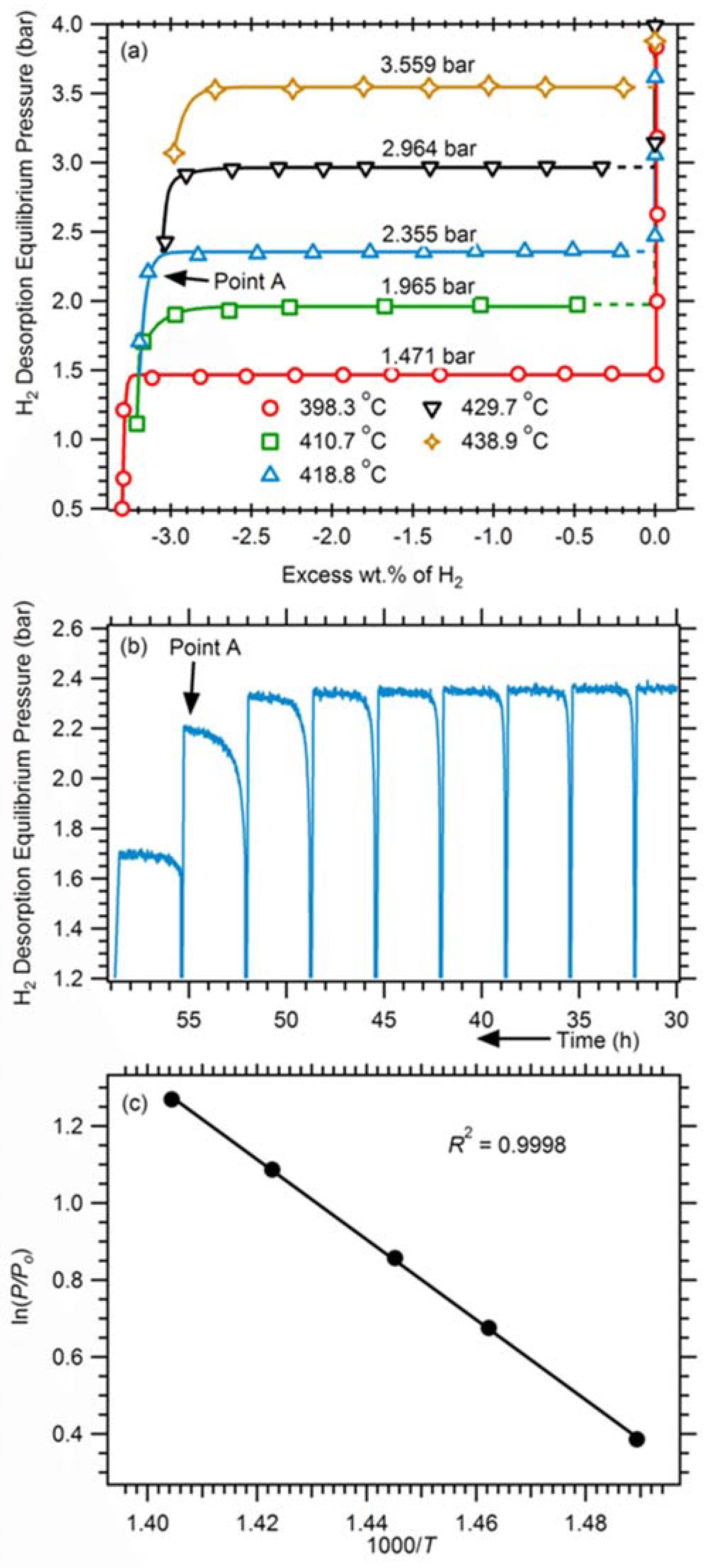
Figure 8.
SEM images of (a) 325 mesh Mg, (b) Mg nanoparticle sample, (c) milled Mg50Co50 BCC alloy, (d) cross-section observation of Mg thin film without Pd layer, (e) top view of Mg thin film without Pd layer and (f) top view of Pd capped Mg thin film. Reproduced with the permission from [78], Copyright Elsevier, 2014.

Figure 9.
Kinetic performance of Ti-catalyzed and commercial MgH2. Reproduced with the permission from [34], Copyright Elsevier, 2012.
Figure 9.
Kinetic performance of Ti-catalyzed and commercial MgH2. Reproduced with the permission from [34], Copyright Elsevier, 2012.

Figure 10.
BSE micrographs of the pellets hydrogenated to 80–90% of maximum theoretical hydrogen storage capacity ((a,b) Mg pellet; (c,d) Mg-2 wt % MWCNTs; and (e,f) Mg-2 wt % Fe). Proposed mechanism of MgH2 nuclei growth in the pure Mg (g) and magnesium containing carbon nanoparticles (h). Reproduced with the permission from [81], Copyright Elsevier, 2017.


Table 1.
Power from different renewable sources in the earth [6].
Table 1.
Power from different renewable sources in the earth [6].
| Renewable Source | Max. Power (TW) | Percentage of Total Solar Energy |
|---|---|---|
| Total surface solar [7] | 85,000 | 100% |
| Desert solar [6] | 7,650 | 9% |
| Ocean thermal [8] | 100 | 0.12% |
| Wind [9] | 72 | 0.08% |
| Geothermal [10] | 44 | 0.05% |
| River hydroelectric [11] | 7 | 0.008% |
| Biomass [6] | 7 | 0.008% |
| Open ocean wave [12] | 7 | 0.008% |
| Tidal wave [13] | 4 | 0.003% |
| Coastal wave [14] | 3 | 0.003% |
Table 2.
Physical properties of different types of heat storage materials.
| Heat Storage Method | Materials | Specific Heat (kJ/kg/K) | Energy Density (GJ/m3) | Working Temperature (°C) | Reference |
|---|---|---|---|---|---|
| Sensible heat | Rock | 1.30 | n.a. | 200−300 | [25] |
| Concrete | 0.85 | n.a. | 200−400 | [25] | |
| Mineral oil | 2.60 | n.a. | 200−300 | [1] | |
| Carbonate salts | 1.80 | n.a | 450−850 | [26] | |
| Latent heat | KNO3/KCl | 1.21 | n.a. | 320 | [1] |
| E117 (commercial) | 2.61 | 0.25 | 117 | [1] | |
| A164 (commercial) | n.a. | 0.46 | 164 | [1] | |
| AlSi12 | 1.04 | 1.51 | 576 | [1] | |
| Na2CO3 | n.a. | 0.70 | 854 | [25] | |
| Chemical heat | Calcium carbonate | n.a | 4.40 | 800−900 | [27] |
| Iron carbonate | n.a. | 2.60 | 180 | [28] | |
| Metal hydrides | n.a. | 4.00 | 200−500 | [29] | |
| Magnesium oxide | n.a. | 3.30 | 250−400 | [1] | |
| Hydroxides | n.a. | 3.00 | 500 | [29] |
n.a.: Not available.
Table 3.
Typical chemical storage materials and reactions. Reprinted with permission [1].
Table 3.
Typical chemical storage materials and reactions. Reprinted with permission [1].
| Compound | Reaction | Material Energy Density | Reaction Temperature (°C) |
|---|---|---|---|
| Ammonia [30] | NH3 + ΔH ↔ 1/2N2 + 3/2H2 | 67 kJ/mol | 400–500 |
| Methane/water [29] | CH4 + H2O ↔ CO + 3H2 | n.a. | 500–1000 |
| Hydroxides [29] | Ca(OH)2 ↔ CaO + H2O | 3 GJ/m3 | 500 |
| Calcium carbonate [27] | CaCO3 ↔ CaO + CO2 | 4.4 GJ/m3 | 800–900 |
| Iron carbonate [28] | FeCO3 ↔ FeO + CO2 | 2.6 GJ/m3 | 180 |
| Metal hydrides [29] | Metal xH2 ↔ metal yH2 + (x − y) H2 | 4 GJ/m3 | 200–500 |
| Metal oxides (Zn and Fe) [31] | e.g., 2-step water splitting using Fe3O4/FeO redox system | n.a. | 2000–2500 |
| Aluminium ore alumina [1] | n.a. | n.a. | 2100–2300 |
| Methanolation–demethanolation [32] | CH3OH ↔ CO + 2H2 | n.a. | 200–250 |
| Magnesium oxide [1] | MgO + H2O ↔ Mg (OH)2 | 3.3 GJ/m3 | 250–400 |
n.a.: Not available.
Table 4.
Thermal and kinetic properties of several types of Mg-based materials. Reprinted with the permission from [78], Copyright Elsevier, 2014.
Table 4.
Thermal and kinetic properties of several types of Mg-based materials. Reprinted with the permission from [78], Copyright Elsevier, 2014.
| Sample | Heat Capacity (kJ/kg/K) | Thermal Conductivity (W/m/K) | Hydrogen Absorption Kinetics |
|---|---|---|---|
| 325 mesh Mg | 1.046 | 10.42 | poor |
| Mg single crystal (0001) | 1.082 | 168.0 | poor |
| Mg nanoparticles | 0.954 | 4.985 | good |
| Mg50Co50 bcc alloy | 0.594 | 0.432 | superior |
| Pd capped Mg thin film | 1.020 | 82.0 | superior |
© 2018 by the authors. Licensee MDPI, Basel, Switzerland. This article is an open access article distributed under the terms and conditions of the Creative Commons Attribution (CC BY) license (http://creativecommons.org/licenses/by/4.0/).
Share and Cite
MDPI and ACS Style
Li, B.; Li, J.; Shao, H.; He, L. Mg-Based Hydrogen Absorbing Materials for Thermal Energy Storage—A Review. Appl. Sci. 2018, 8, 1375. https://doi.org/10.3390/app8081375
AMA Style
Li B, Li J, Shao H, He L. Mg-Based Hydrogen Absorbing Materials for Thermal Energy Storage—A Review. Applied Sciences. 2018; 8(8):1375. https://doi.org/10.3390/app8081375
Chicago/Turabian StyleLi, Bo, Jianding Li, Huaiyu Shao, and Liqing He. 2018. "Mg-Based Hydrogen Absorbing Materials for Thermal Energy Storage—A Review" Applied Sciences 8, no. 8: 1375. https://doi.org/10.3390/app8081375
Note that from the first issue of 2016, this journal uses article numbers instead of page numbers. See further details here.