Interface Engineering Strategies for Fabricating Nanocrystal-Based Organic–Inorganic Nanocomposites


1
Department of Materials Science and Engineering, Hongik University, Sejong 30016, Korea
2
School of Polymer Science and Engineering, Chonnam National University, Gwangju 61186, Korea
3
Alan G. MacDiarmid Energy Research Institute, Chonnam National University, Gwangju 61186, Korea
*
Authors to whom correspondence should be addressed.
Appl. Sci. 2018, 8(8), 1376; https://doi.org/10.3390/app8081376
Submission received: 9 July 2018
/
Revised: 7 August 2018
/
Accepted: 13 August 2018
/
Published: 15 August 2018
(This article belongs to the Section Nanotechnology and Applied Nanosciences)
Abstract
:Hybrid organic–inorganic nanocomposites have attracted considerable attention because they have the advantages of both conjugated polymers (CPs) and nanocrystals (NCs). Recent developments in the interfacial engineering of CP–NC organic–inorganic nanocomposites enabled the formation of an intimate contact between NCs and CPs, facilitating electronic interactions between these two constituents. To design CP–NC nanocomposites, several approaches have been introduced, including ligand refluxing, direct grafting methods, direct growth of NCs in proximity to CPs, and template-guided strategies. In this review, the general reactions of ligand exchange processes, purification methods, and characterization techniques have been briefly introduced. This is followed by a highlight of recent advances in the synthesis of hybrid CP–NC nanocomposites and newly developed inorganic surface treatments, as well as their applications. An outlook for future directions in this area is also presented.

1. Introduction
Hybrid organic–inorganic nanocomposites, composed of semiconductor nanocrystals (NCs) and conjugated polymers (CPs), have garnered significant attention because they offer promising opportunities for the development of optoelectronic devices, including light-emitting diodes (LEDs) [1,2], photovoltaic cells [3], sensors [4,5,6], and tunable lasers [7,8,9]. The size-dependent physical and chemical properties of NCs can be easily tailored by tuning their morphology and composition, paving the way for a wide range of opto-electronic applications [10,11]. CPs have different advantages, including low weight, flexibility, solution processability, low cost, and large-area production [12,13]. Moreover, organic–inorganic hybrid nanocomposites possess large interfacial areas, which can be beneficial to obtain high reactivity in solar cells and electrochemical applications [14,15].
In this context, different types of nanocrystals have been incorporated into the CP matrices. For example, semiconductor NCs (e.g., CdSe and PbS quantum dots (QDs)) have been mixed with CPs (e.g., poly(3-hexylthiophene) (P3HT) and poly(2,6-bis(3-n-dodecylthiophen-2-yl)-alt-N-dodecyldithieno[3,2-b:2′,3′-d]pyrrole) (PDTPBT)) for photovoltaic applications [3,16]. However, simple physical mixing of NCs and CPs often results in micro-scale phase agglomeration, which fails to fully exploit the large interfacial areas of NCs/CPs [8,17,18,19,20,21,22]. Moreover, the insulating aliphatic organic ligands capped on the NC surface hamper the electronic interactions between NCs and CPs.
To overcome this problem, several approaches have been introduced for constructing organic–inorganic nanocomposites, including ligand refluxing, direct grafting methods, in situ growth of NCs in the presence of CPs, and template growth [23,24,25,26,27]. The direct grafting technique involves ligand refluxing with bifunctional ligands and chemical coupling with end-functionalized CPs. Pyridine or short-chain amines are generally used to introduce bifunctional ligands onto NC surfaces. In the in situ growth method, both nucleation and growth are initiated in the presence of CPs, yielding hybrid CP–NC nanocomposites. However, the precise control of NCs in the presence of CPs remains challenging.
Conventional ligand refluxing often results in remnants of fatty aliphatic ligands on the NC surface, despite repeated purification procedures, detrimentally affecting the opto-electronic performance [28]. To this end, ligand exchange methods have been introduced involving inorganic ligands, such as molecular metal chalcogenide complexes, chalcogenide ions, and halide ligands [29]. It is a simple yet effective route to completely remove the original insulating organic ligands and introduce the desired ligands on the NC surface. Compared with conventional ligand exchange approaches (e.g., pyridine and short-chain amines), ligand exchange using inorganic ligands effectively displace both covalently bonded ligands (i.e., X-type) and dative-bonded ligands (i.e., L-type) on the NC surface [29].
This review seeks to summarize the recent progress in the surface treatment of NCs and the synthesis of organic–inorganic hybrid nanocomposites. The interfacial engineering of NCs, including purification, characterization, and development of synthetic techniques, has been presented. Furthermore, the advances in surface treatment, using inorganic ligands for the design of CP–NC nanocomposites, have been highlighted.
2. Overview of Ligand Exchange
2.1. Ligand Exchange
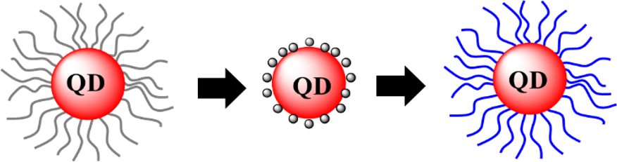
Ligand exchange is the process of introducing desired ligands on NCs by displacing originally bound surfactants, considering the adsorption and desorption kinetics. Hence, the reaction rates are key factors determining the coverage of ligands. The reactions and rates can be described as follows [30]:
where M and L are the binding sites on the NC surfaces and the free ligands, respectively. ML refers to the NC surface sites that bind the ligands. The terms kad and kdes refer to the adsorption and desorption reaction rate constants, respectively. The average surface ligand coverage (θ) can be therefore expressed as θ = [ML]/([M] + [ML]). For a given system, the number of total binding sites ([M] + [ML]) is constant. Equations (1) and (2) can thus be rewritten in terms of the change in the average surface ligand coverage, :
Ligand exchange: M + L → ML
It should be noted that θ depends on the concentration of ligands, kad, and kdes.
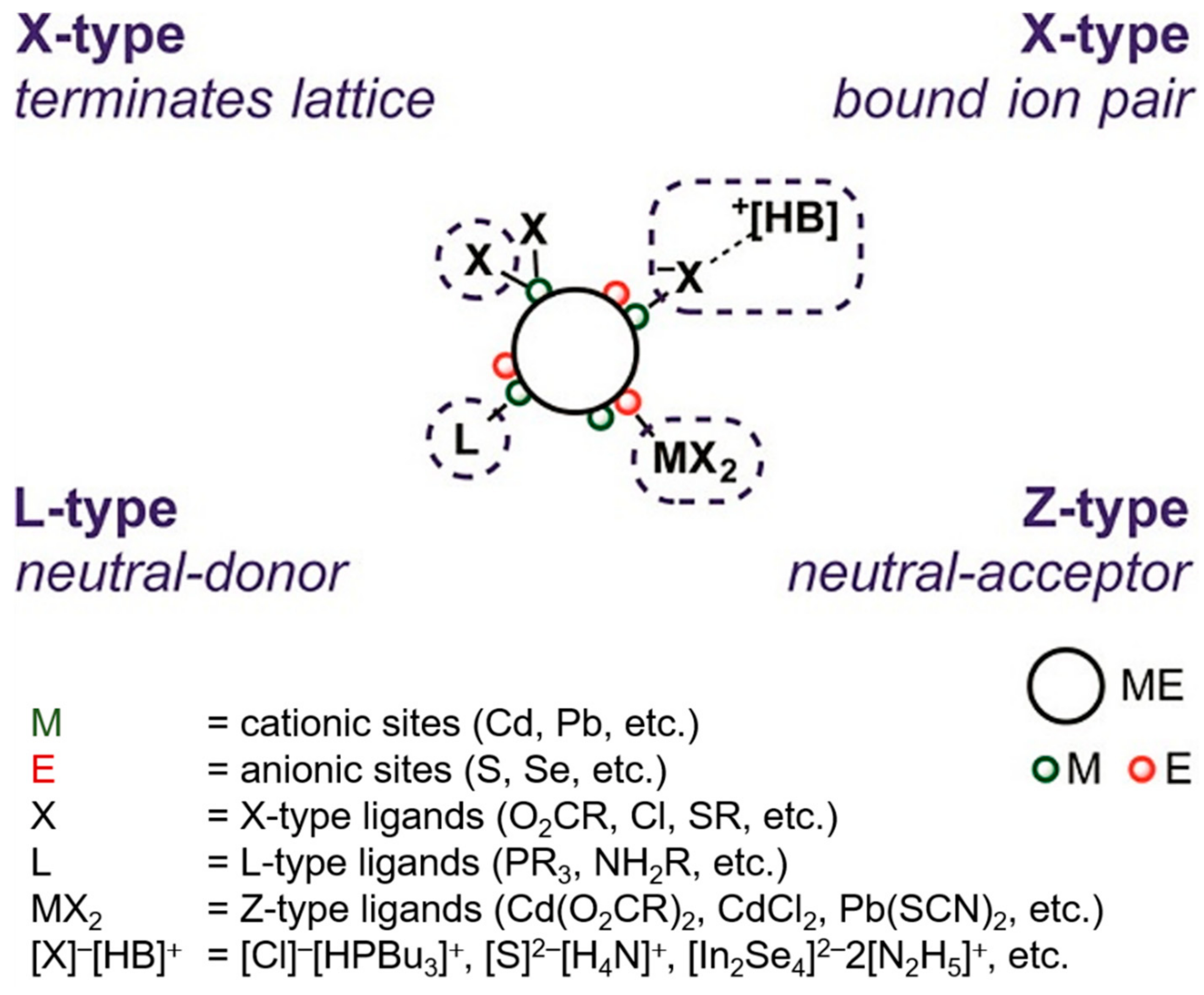
The reaction rate constants are governed by the chemical nature of the ligands, such as the steric effects, mobility, and binding ability of the functional groups. The binding mode plays an especially significant role in the adsorption–desorption reaction. As illustrated in Figure 1, the binding mode of ligands with NC surfaces can be classified into three types, according to the suggested method by Green et al.: (1) L-type ligands (2) X-type ligands; and (3) Z-type ligands [31]. L-type ligands are two-electron donors (neutral Lewis bases) and bind to NCs via dative covalent bonding. X-type ligands donate one electron to NCs (cationic sites) and form covalent bonds. Z-type ligands are two-electron acceptors (Lewis acids). The nature of the ligands strongly depends on the stoichiometry of the NCs. The charge neutrality is maintained by balancing the metal cations on NC surfaces with X-type anionic ligands. Therefore, it is necessary to transfer protons to mediate the ligand exchange. Moreover, the fact that metal enrichment increases with decreasing nanocrystal size emphasizes the importance of stoichiometry [32,33].
Owen and co-workers demonstrate that the surface metal ions are labile; thus, they can reversibly bind to and dissociate from NCs by forming carboxylate complexes (M(O2CR)2) [32]. NMR characterization revealed that various Lewis bases like tri-n-butylamine, tetrahydrofuran, N,N-dimethyl-n-butylamine, tri-n-butylphosphine, N,N,N′,N′-tetramethylbutylene-1,4-diamine, pyridine, N,N,N′,N′-tetramethylethylene-1,2-diamine, n-octylamine can mediate the ligand exchange. The addition of L-type ligands (e.g., N,N,N′,N′-tetramethylethylene-1,2-diamine (TMEDA)) leads to the detachment of the original capping ligands, which is oleic acid (OA, X-type). This, however, disrupts the charge neutrality due to the positive sites on NCs and the anionic ligands and strongly indicates that the detached carboxylic fragment is formed by TMEDA-bound cadmium carboxylate complexes displaced for charge neutrality. The potency of displacing Z-type ligands with L-type ligands was 35–40 ± 5% (2.0 M) for primary amines and TMEDA and 95 ± 10% (2.0 M) for pyridine and Bu3P.
The electronic nature, chelation, and steric effect play important roles in determining the ligand displacement potency. For example, Bu3P is more effective than tri-n-butylamine (Bu3N) and primary amines are more effective than primary alcohols due to their different electronic properties (for example, polarizability). The chelating ability of the ligands also strongly influences the ligand displacement effectiveness. For example, TMEDA, which has a strong chelating ability, is an effective displacement reagent than N,N-dimethyl-n-butylamine (Me2NBu), which has a lower chelating ability. Finally, the steric hindrance of the ligand has a significant impact on its displacement potency.
2.2. Purifications
The synthetic procedures for high-quality NCs frequently rely on an excess of surfactants to provide enough colloidal stability and to control the morphology [34]. However, the remaining insulating ligands and by-products generated by the decomposition of reagent compounds have negative effect on the physical and chemical properties of the as-synthesized NCs [35]. Accordingly, effective means for eliminating these byproducts and excess insulating ligands are greatly required. The most common and simple purification method is a precipitation and re-dissolution protocol, which involves the precipitation of colloidal nanocrystals from the solution by a non-solvent. Specifically, anti-solvents (i.e., polar solvents) are first added to induce the flocculation of NCs dispersed in non-polar solvents by increasing the solvent polarity. The supernatant solution, which contains the by-products and excess surfactants, is then discarded and the purified NCs are re-dispersed in clean solvents [36]. Toluene or chloroform as the anti-solvent and methanol or acetone as the solvent are the most commonly used combinations this far [37,38,39].
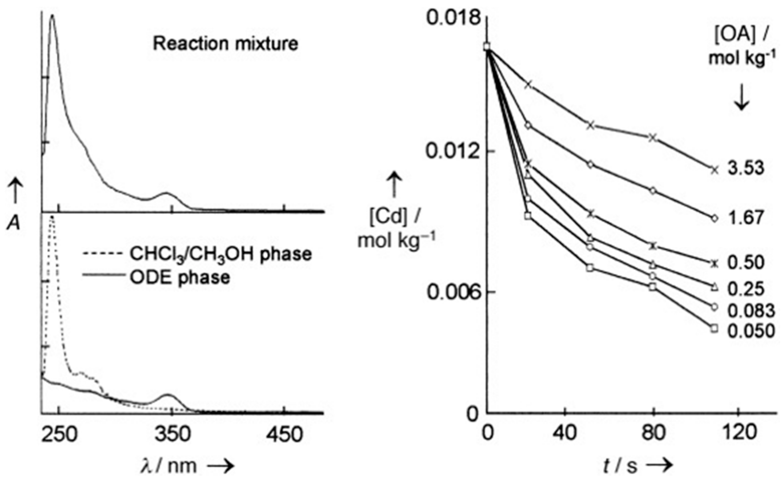
An alternative purification technique involving extraction uses immiscible solvents. Metal complex by-products and excess surfactants are extracted via phase transfer from a non-polar to a polar solvent, because they are more soluble in the latter. For example, a chloroform/methanol mixture (1:1 ratio) was used to extract both cadmium oleate and oleic acid from a CdS NCs/octadecene (ODE) solution [34,40]. The transfer of by-products and excess ligands can be confirmed by Fourier transform infrared (FTIR) and ultraviolet (UV)-visible (vis) spectroscopy results. For example, Yu et al. used UV-vis measurements to confirm that the amount of oleic acid in a CdSe NCs/ODE phase decreased upon stirring with extracting solvents (i.e., 1:1 chloroform/methanol) (Figure 2) [40].
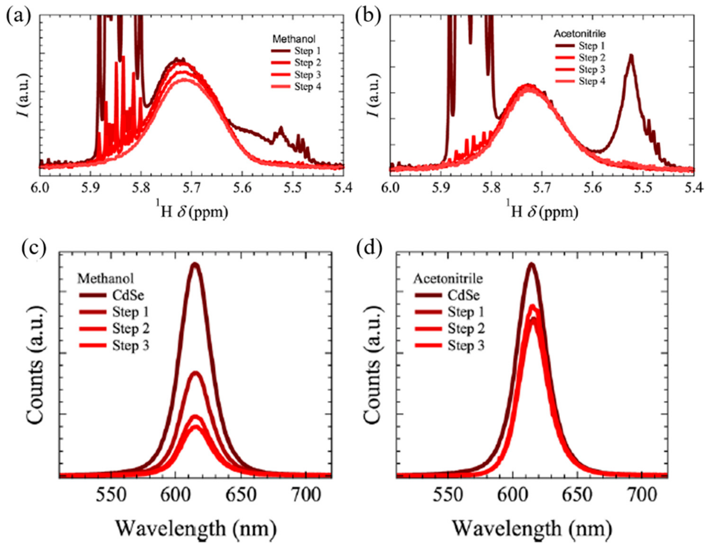
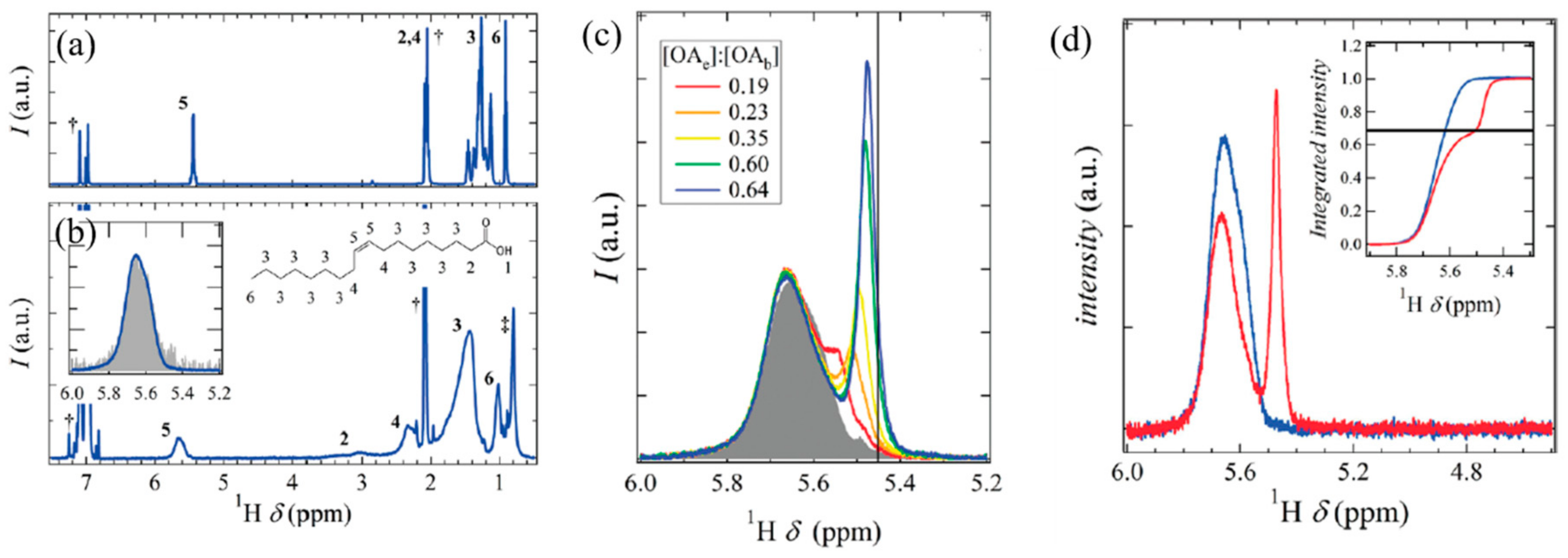
Recent studies reveal that the use of protic solvents (e.g., methanol) as anti-solvents sometimes results in the detachment of covalently bound ligands and the introduction of methoxide functionalities on NC surfaces via proton exchange [41,42]. This adversely influences the optical properties of the synthesized semiconducting nanocrystals, such as photoluminescence (PL) quenching due to the formation of mid-gap trapping sites [17,43]. In this context, an aprotic anti-solvent, i.e., acetonitrile, has been successfully used to prevent the formation of alkoxy functional moieties on NC surfaces [41]. Oleic acid-capped CdSe QDs were subjected to repeated precipitation and resuspension procedures with methanol and acetonitrile, respectively. Interestingly, in a another study, 1H NMR observation of a proton signal from the alkene moiety of oleic acid revealed that the use of acetonitrile as a precipitant leaves the bound surfactants untouched, while the employment of short-chain alcohols (e.g., methanol, ethanol, and isopropanol) induced the release of carboxylate ligands (Figure 3a,b) [33]. Notably, the broadening of this peak corresponds to bound-state ligands (i.e., oleic acid (OA)), while the peak sharpening indicates free-state ones. Clearly, the precipitation/resuspension with methanol produced a sharp signal around 5.8 ppm, strongly suggesting that the detachment of OA (free-state ligands) is due to proton transfer from methanol to OA [33]. In stark contrast, the proton signal remained broad when acetonitrile was used during the precipitation/resuspension procedure [44], further confirmed using PL measurements. The emission intensity can be used as evidence for the replacement of ligands because the loss of OA ligands is strongly correlated with PL quenching (Figure 3c,d). The photoluminescence spectrum of OA-capped CdSe QDs was recorded after successive purifications using methanol and acetonitrile. The use of methanol leads to considerable loss of photoluminescence, suggesting the formation of methoxide moieties on the CdSe QD surface [44]. On the other hand, the initial photoluminescence was preserved even after repeated purification with acetonitrile [33,41].
2.3. Characterization
Characterization techniques used thus far to investigate the surface properties of NCs include X-ray photoelectron spectroscopy [45,46], UV-vis spectroscopy [47], infrared spectroscopy [48], photoluminescence spectroscopy [49,50,51], and nuclear magnetic resonance (NMR) spectroscopy [52,53]. To determine the properties of surface ligands or the interfacial properties between organic and inorganic elements, various characterization techniques must be combined [54]. Among these, NMR spectroscopy is one of most powerful and common characterization techniques for identifying ligands on the nanocrystal surface. It can effectively verify the type of ligands by detecting a unique spectral signature without any destruction of samples. Moreover, it enables discrimination between bound ligands and free ones by observing the broadened NMR resonance of protons within surface-bound species [55]. Based on this broadening effect, one-dimensional (1D) 1H NMR spectroscopy can be employed to monitor the behavior of ligands on NC surfaces.
The binding nature of carboxylic acid ligands with CdSe QDs has been studied using 1H NMR measurements in several studies [56,57,58]. The comparison of the different proton signals from the free-state OA ligands and purified OA-capped CdSe QDs is shown in Figure 4a,b [59]. The addition of excess OA ligands to a purified OA-QDs solution resulted in the generation of a new and separate set of sharp resonance peaks next to those due to bound OA, along with broadening of the alkene proton resonance peaks (Figure 4c). Intriguingly, the intensity of bound OA ligands remains constant, indicating that the number of tightly bound OA ligands is not affected despite the addition of excess OA [56]. This, however, does not mean that there is no adsorption–desorption reaction. In order to verify the existence of an equilibrium transfer, deuterated OA (OA(9,10)-d2), i.e., OA that has its alkene hydrogen replaced by deuterium, was added to OA-CdSe QDs in a toluene-d8 solution. Interestingly, the intensity of the broadened resonance peak at 5.65 ppm, ascribed to the alkene proton of bound OA, decreased, while the sharpened signal, attributed to free OA, increased (Figure 4d). The decrease in intensity of the alkene resonance is also proportional to the amount of OA(9,10)-d2 added. These observations indicate that all the bound OA ligands are involved in the exchange [59].
Diffusion-ordered NMR spectroscopy (DOSY) is a useful and powerful tool for distinguishing between surface-bound and free ligands. It measures the diffusion coefficients of species associated with proton resonances, determining their hydrodynamic radii (using the Stokes–Einstein relation). For example, DOSY was used to measure the hydrodynamic radii of free ligands (e.g., OA) and that of ligands bound to NCs (i.e., OA-CdSe QDs) in an OA/CdSe QDs system. Their estimated values were 0.56 nm and 4.2 nm, respectively, in a THF solvent [32]. Clearly, the hydrodynamic radius is higher for OA-capped QDs than for free OA. Nuclear Overhauser spectroscopy (NOESY) is also a well-known technique for assigning 1H NMR signals to free and bound ligands [44]. It measures the enhanced cross-coupling NMR signals originating from dipole–dipole interactions among protons within the same molecules when they are immobilized on slowly tumbling objects, such as NCs.
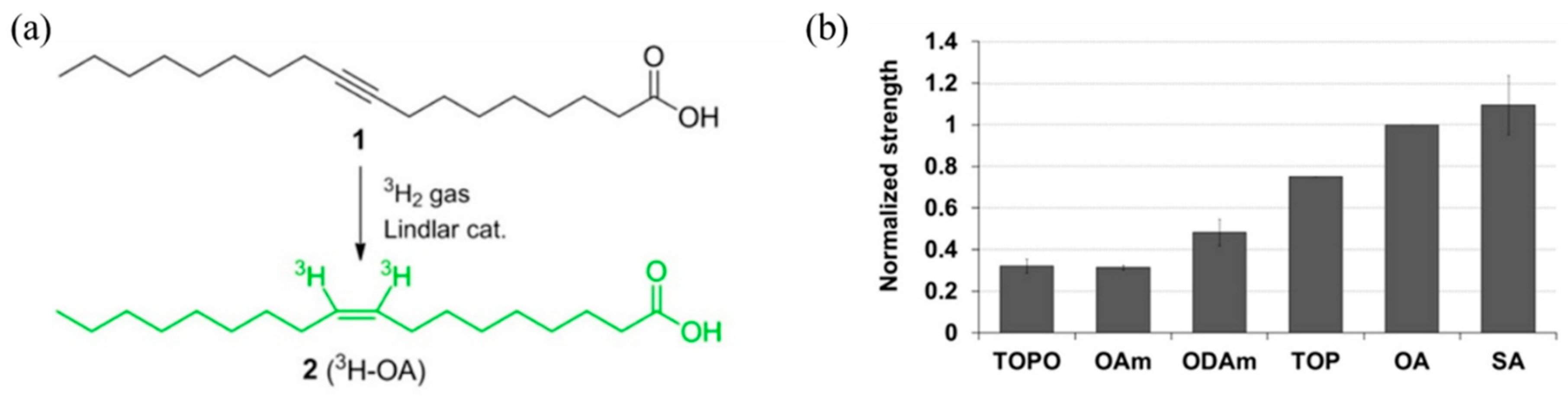
An alternative technique based on radioactive labeling was developed by Doris et al. to effectively detect ligands in minute amounts. The technique uses tritium (3H) as a radioactive tracer for the quantification of ligands bound to the QDs [60]. This strategy offers an advantage compared to NMR characterization in that picomolar-scale detection is feasible due to the high sensitivity of the 3H nuclei. Specifically, 3H-labeled oleic acids were first prepared via partial reduction of stearolic acid in the presence of tritium gas; then, OA bound to NCs were replaced with isotopically labeled OA ligands, yielding 3H-labeled OA-capped QDs (Figure 5a). The 3H-labeled OA-capped QDs were used as starting materials and were subjected to ligand refluxing with various ligands (e.g., trioctylphosphine (TOP), trioctylphosphine oxide (TOPO), OA, and oleylamine) to quantify and understand ligand exchange behaviors. Through the detection of a radioactive species (i.e., 3H-labeled OA), a relative scale of OA displacement strength was established for different ligands (Figure 5b) [60].
For many applications including LEDs, lasers, and bioimaging, the actual concentration of the NCs in solution must be determined. Although thermogravimetric methods are often used to determine the concentration of colloidal nanocrystals, the existence of organic ligands on NC surface hinders accurate measurement. In addition, such techniques are destructive, making an in situ characterization impossible. In this regard, absorption spectroscopy is as an excellent and convenient tool for quantification of semiconducting nanocrystals without damaging the samples. Furthermore, the size of the semiconducting nanocrystals can be determined based on the quantum confinement effect.
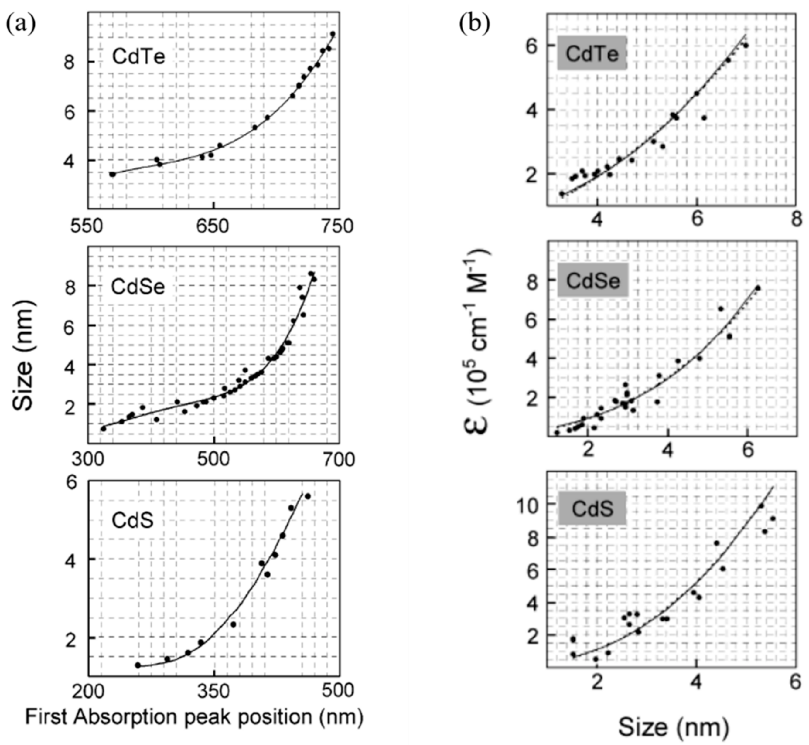
Several researchers have reported a correlation between the first absorption peak of semiconducting QDs (e.g., CdS, CdSe, PbTe, PbSe, and CdTe) and their size. Peng et al. summarized these values and suggested empirical fitting functions [40,46,47]. These equations are only valid in the size range covered by the data shown in Figure 6 [47]. The optical properties of the semiconducting quantum dots are summarized in Table 1 [40,47].
The relationship between molar extinction coefficient (ε) and NC size has been reported by several groups. It greatly relies on the NC concentration, based on Beer–Lambert’s equation [47]. Therefore, the main obstacle for calculating ε has been the difficulty in determining the QD concentrations [10,46,61]. In the early studies, the extinction coefficient per NC was determined by measuring the NC concentration, based on precursor mass, assuming that all the precursors are converted into NCs. However, this inaccurate assumption resulted in discrepancies in the results and more sophisticated measurement techniques have since been developed, such as inductively coupled plasma mass spectrometry (ICP-MS) and atomic absorption measurements [62]. For example, Nozic’s group measured the extinction coefficient of InAs QDs as a function of their size using ICP-MS [62]. The NC concentration was also accurately determined via standard atomic absorption measurements. In detail, a purified NC solution was digested by aqua regia and the cadmium concentration was measured by atomic absorption spectroscopy; this enabled a more accurate calculation of NC concentration by calculating the number of Cd atoms per NC crystal. It is worth noting that a purification procedure that removes excess cadmium precursor is extremely important for accurate determination of NC concentration. In this study, the excess metal precursors were removed by an extraction method (i.e., methanol and CHCl3 extraction, as described above); the extraction was confirmed using UV-vis measurements.
The value of the extinction coefficient can be further confirmed by controlled etching of the nanocrystals in a solution with a definite volume [63,64]. This ensures that the etching of NC occurs homogenously and that the concentration of NCs in the solution is unchanged. The etching of CdSe and CdTe was achieved by benzoyl peroxide and HCl, respectively [47]. The absolute value of ε, measured by the controlled etching methods, was in good agreement with the experimental results. The value of ε at the first absorption peak was found to be independent of the temperature, the nature of the capping ligands, and the polarity of solvents [47].
2.4. Organic–Inorganic Hybrid Nanocomposites
Ligand exchange through refluxing has been demonstrated to be a simple and effective method to bind CP ligands to a NC surface. For example, oligomer ligands (e.g., pentathiophene phosphonic acid and terthiophene phosphonic acid) that have functionalities for anchoring to NC surfaces were tethered onto the surface of CdSe NCs via ligand refluxing [24,28]. The resulting oligohexylthiophene-capped CdSe NCs showed excellent solubility in most organic solvents and good miscibility with CPs. Querner et al. grafted carbodithioate–oligothiophenes onto a CdSe QD surface via ligand exchange for solar cells [65].
Since ligand exchange relies on the kinetics of the adsorption–desorption process, the grafting density of long-chain CPs on NC surfaces is usually low. To address this entropic penalty, short-chain bifunctional ligands are introduced on NC surfaces through ligand refluxing, followed by grafting with the desired CPs [66]. Rationally designed bifunctional ligands (e.g., arylbromide-functionalized phosphine oxides or thiols) were tethered to the CdSe NC surfaces and then grafted with end-functionalized P3HT, yielding P3HT-CdSe NC nanocomposites (Figure 7) [24]. The grafting density was 250 and 400 P3HT chains per CdSe nanorod (NR) for phosphine oxide- and thiol-functionalities, respectively. This result is in good agreement with the fact that thiol ligands coordinate more effectively than phosphine oxide ligands. Despite the high grafting density, this process involves a two-step procedure and is thus time-consuming.
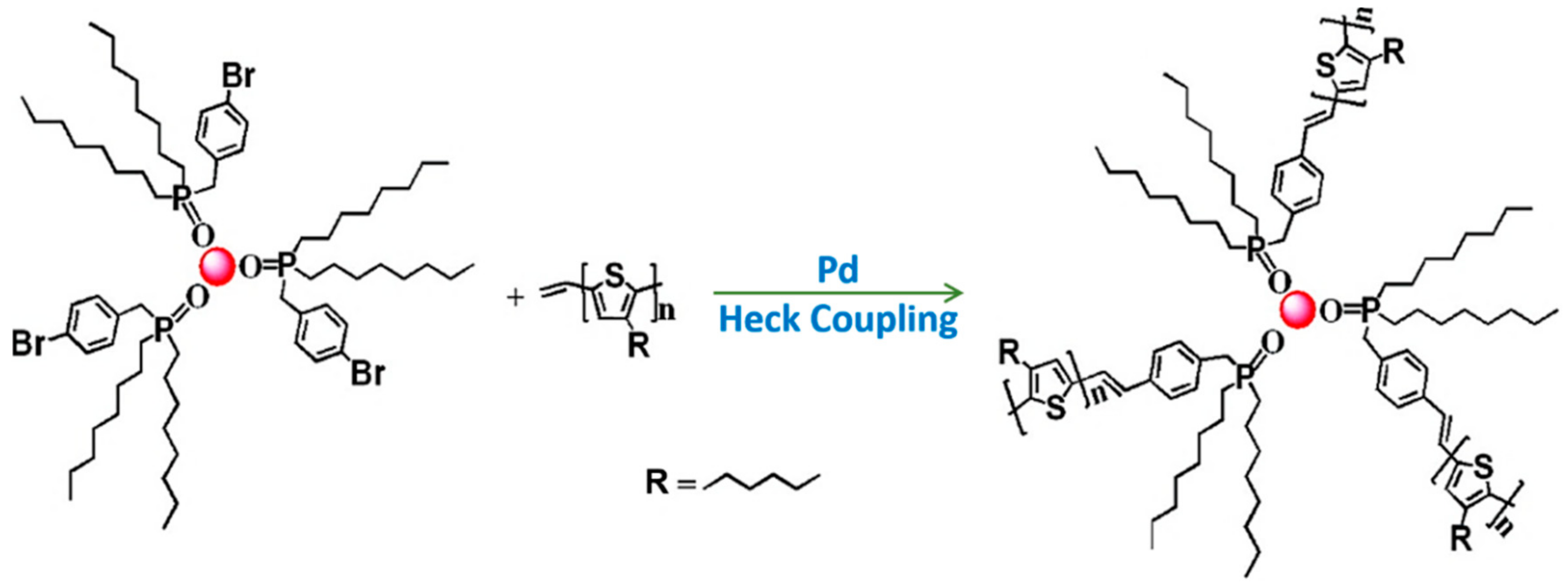
To further simplify the process of forming hybrid nanocomposites, the bifunctional ligand-grafted NCs can be synthesized directly. This dispenses with the need for tedious ligand exchange procedures. Specifically, a bifunctional ligand, 4-bromobenzyl phosphonic acid (BBPA), which coordinates strongly with the and facets of CdSe NCs was used during the synthesis of CdSe NCs, yielding BBPA-capped CdSe NCs [25]. It should be noted that BBPA possesses a bromide moiety that can be used as a chemical coupling site. Subsequently, vinyl- and ethynyl-terminated P3HT were grafted with the bromide group of BBPA-capped CdSe NRs via Heck coupling and click chemistry, respectively. These chemically tethered P3HT-CdSe NC nanocomposites not only showed excellent dispersion in various organic solvents, but also demonstrated improved electronic interactions between the electron-accepting inorganic NCs (e.g., CdTe tetrapods and CdSe QDs) and the electron-donating CPs (e.g., P3HT). Photoluminescence measurements show the facilitated charge transport between these components [26].
Since the use of small fractions of aliphatic ligands is unavoidable, techniques involving direct growth of NCs in proximity to CPs have been studied. It avoids the use of further treatments like ligand refluxing as NCs are directly synthesized in the presence of a CP matrix. Dayal et al. synthesized CdSe NCs in the presence of P3HT by utilizing the steric hindrance from the side chains of P3HT, yielding a simple mixture of CdSe/P3HT [67]. A binary solvent (i.e., octadecene (ODE) and 1,2,3-trichlorobenzene (TCB)) was used to dissolve both cadmium precursors (i.e., dimethylcadmium) and P3HT. Subsequently, selenium precursors in trioctylphosphine were injected into the solution to initiate nucleation and growth.
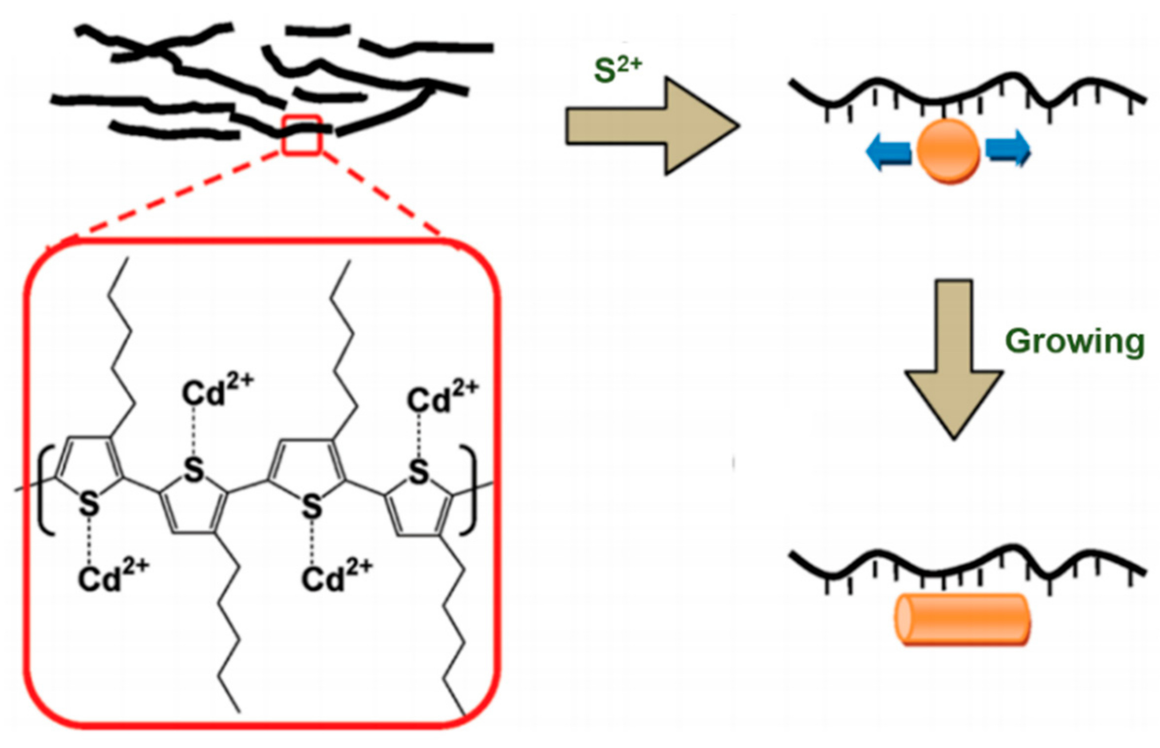
Liao et al. reported on an in situ growth process of anisotropic CdS NCs in a P3HT matrix [27]. A polar solvent, dimethyl sulfoxide (DMSO), was used to dissolve the cadmium precursors, cadmium acetate, and 1,2-dichlorobenzene (DCB) was employed to dissolve P3HT. Similarly, injection of sulfur precursors resulted in intimate contact in the CdS NC/P3HT nanocomposites. Intriguingly, the shape of the NCs evolved from a spherical dot to an NR-like morphology with increasing cadmium precursor concentration. A growth mechanism for the formation of NRs was proposed: CdS NRs were grown along the P3HT backbone upon the anchoring of cadmium cations (Cd2+) on the S atoms of P3HT, as schematically illustrated in Figure 8 [27]. This is elucidated by FTIR measurements, where the signal corresponding to the S–C stretching of P3HT shifted after the addition of cadmium acetate into P3HT, suggesting the formation of intermolecular interactions at the expense of the S–C bond energy.
However, such direct growth approaches often result in dangling bonds on the surface, which can act as charge trapping sites. A binary solvent was required to dissolve both metal precursors and polymers (e.g., DCB for P3HT and DSMO for cadmium acetate). Moreover, the resulting CPs/NCs mixture may suffer from poor colloidal stability, resulting in agglomeration of NCs in the polymer matrix because CPs are not chemically tethered onto the NC surface [27,68].
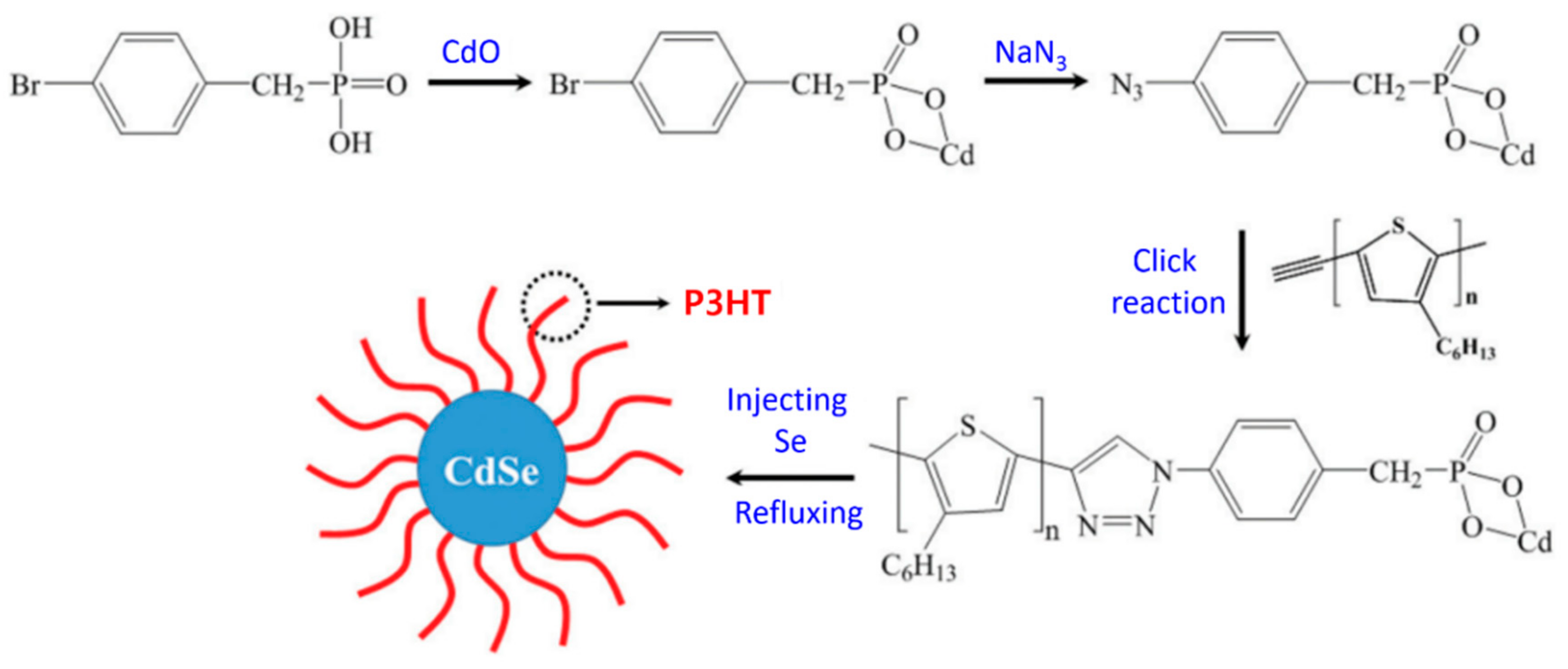
In this respect, an advanced in situ technique to form CP-grafted NCs (i.e., P3HT–CdSe NC nanocomposites) by capitalizing on judiciously designed CP-grafted metal precursors (i.e., Cd-P3HT complexes) was introduced by Jung et al. (Figure 9) [23]. Specifically, CP-grafted precursors (i.e., Cd–P3HT complexes) were first synthesized via a click reaction between ethynyl-terminated P3HT and N3-functionalized Cd-phosphonic acid complexes (i.e., Cd–BPA–N3). Finally, a hot injection of selenium precursors into the Cd–P3HT solution yielded intimately contacted P3HT-grafted CdSe NCs. The formation of dangling bonds (e.g., Cd2+ and Se2−), which is unavoidable in the aforementioned conventional in situ growth techniques [27,68], can be greatly reduced when P3HT-grafted Cd complexes are employed. Furthermore, the morphology of the NCs can be controlled to form QDs or tetrapods by precisely tuning the ratio of cadmium precursors to Cd-P3HT [23].
A novel synthetic route to form organic–inorganic hybrid nanocomposites using block copolymer nanoreactors (i.e., templates) to guide direct in situ growth of NCs with precisely controlled dimensions, compositions, and architectures was introduced by Lin’s group [69,70,71]. The synthesized NCs were permanently linked to the CPs, imparting long-term stability of the resulting CP-grafted NC hybrid nanocomposites in various organic solvents. An amphiphilic diblock copolymer, composed of inner hydrophilic and outer hydrophobic blocks, was synthesized from a β-cyclodextrin core. The preferential coordination between the functional groups of the inner hydrophilic blocks and the metal precursors selectively guided the nucleation and growth of NCs. The NCs are thus closely and permanently tethered to the outer CPs, as depicted in Figure 10 [71].
3. Inorganic Ligand Exchange
Despite repeated purification and ligand refluxing, various researchers have reported that detachment of covalently bonded ligands (X-type) does not really occur; rather, they remain on the NC surfaces unless proton transfer is possible [56]. These remaining aliphatic ligands detrimentally affect the optoelectronic properties when used in various applications including LEDs, lasers, and solar cells [9]. Thereby, robust techniques are required for complete removal of insulating aliphatic ligands capped on NCs.
To address this issue, an alternative surface coating method was developed by employing a new class of surface ligands: hydrazine-based metal chalcogenide complexes (MCC) e.g., N2H2-MCCs, (N2H5)4Sn2S6, (N2H4)ZnTe, and N4H9Cu7S4 [72,73]. The complexes are prepared by dissolving metal chalcogenides in N2H4, which possesses a unique solvating and reducing capability. Molecular metal chalcogenide anions (e.g., SnS44−, Sn2S64−, SnTe44−, AsS33−, and MoS42−) solvated in a polar solvent attach to NC surfaces, replacing the original bulky organic ligands and providing colloidal stability. MCC-treated NCs were prepared via a simple phase transfer of NCs from the non-polar to the polar solvent. Specifically, aliphatic-ligand-capped NCs dispersed in a non-polar solvent (e.g., hexane) were transferred to a polar solvent containing hydrazine-chalcogenide anions, indicating successful displacement of the insulating ligands. It is worth noting that MCCs enable stable and facile electronic interactions between NCs and provides colloidal stabilization by adhering to the NCs. The zeta potential measurements of the NC surface show excellent dispersion of NCs in a polar solvent despite the lower steric hindrance of MCCs than the bulky aliphatic ligands. TGA characterization showed that the 2–10 wt % of MCCs is sufficient to stabilize colloidal NCs in variety of solvents [72]. Intriguingly, the utilization of N2H4 results in thermal decomposition of N2H4–MCCs into metal chalcogenides, which act as an electronic glue. The FTIR peaks attributed to C–H, S–H, and N–H bonding completely disappeared, demonstrating successful ligand detachment. Indeed, the film fabricated with MCC-treated NCs (e.g., (N2H5)2Sn2S6-capped Au, and (N2H5)2Sn2S6-capped CdSe NCs) showed improved conductivity when used in field-effect transistors [72].
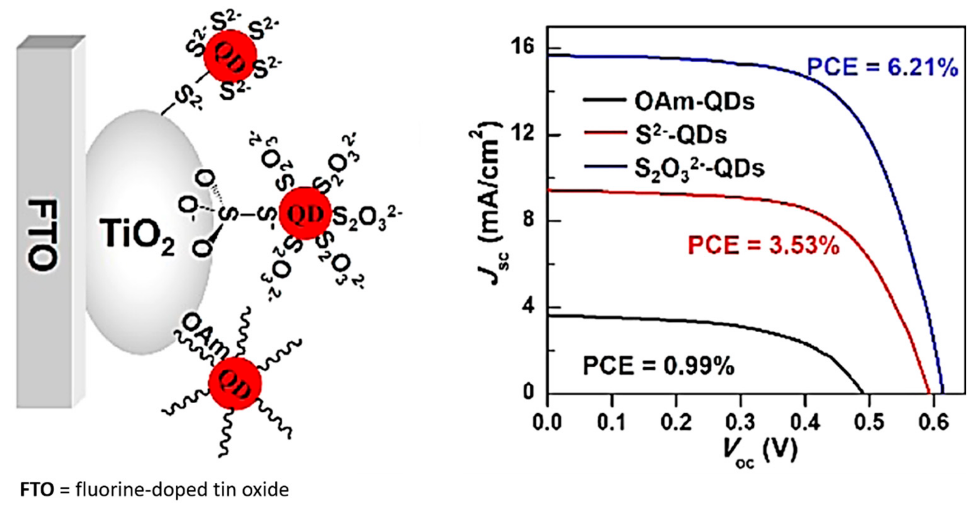
However, hydrazine is not only highly toxic and unstable, but it also strongly alters the properties of NCs owing to its strong chemical reactivity. Thus, environmentally benign and air-stable synthetic routes to form MCC-capped NCs have been developed. These techniques use metal sulfide MCCs such as Na4SnS4, Na4Sn2S6, Na3AsS3, (NH4)4Sn2S6, and (NH4)3AsS3 instead of hydrazine–MCCs [74,75]. Treatment with these metal sulfide MCCs has been applied to a wide range of NCs, including CdS, CdSe, CdSe/ZnS, CdTe, PbS, PbTe, Au, and FePt. It should be highlighted that CdSe and PbS QDs retain their luminescent properties even after repeated ligand exchange, which is in contrast to the observation after a N2H2–MCCs treatment. FTIR studies demonstrated the successful displacement of aliphatic ligands with metal sulfide MCCs. The surface coverage of SnS4− ligands on NCs was ~20.8%, based on ICP-OES measurements. This approach, however, is not applicable to metal oxides and dielectrics; thus, more generalized techniques for surface functionalization are necessary. The devices fabricated with MCC-capped NCs exhibited improved performance when used in QD-sensitized solar cells (Figure 11) [76].
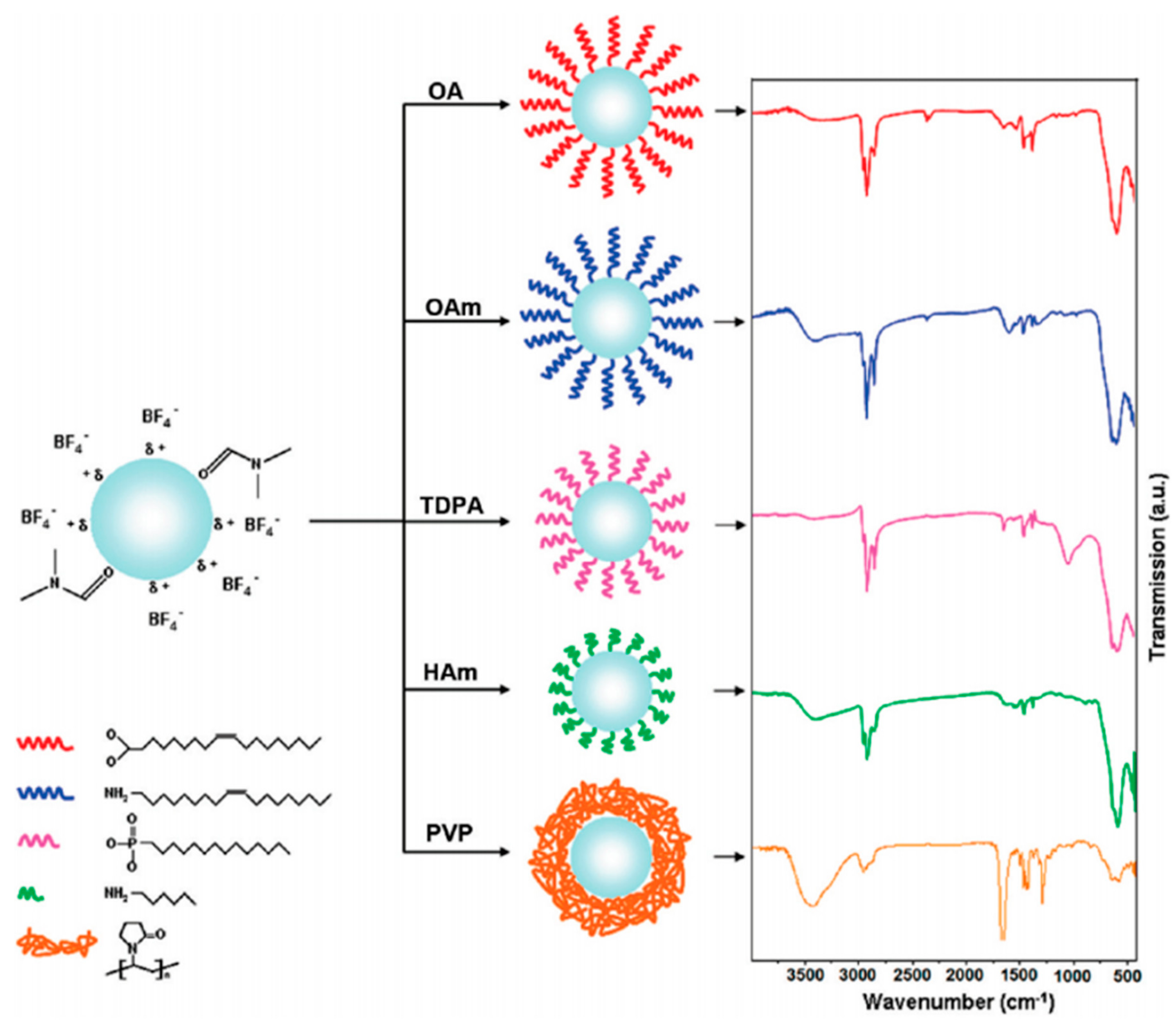
In this regard, Murray et al. introduced a generalized ligand exchange strategy that can be applied to metal oxides (e.g., Fe3O4 and TiO2,), metal alloys (FePt and CoPt3), and dielectrics (NaYF4) [77]. The strategy involves the use of nitrosonium tetrafluoroborate or diazonium tetrafluoroborate compounds to replace original ligands and introduce BF4− anions on NC surfaces, thus stabilizing the NCs in various polar solvents such as N,N-dimethylformamide (DMF), dimethylsulfoxide (DMSO), and acetonitrile. The reactive nature of NO+ with solvated water resulted in the release of a considerable number of protons, thus facilitating the removal of organic ligands by protonation. It is worth noting that the failure of detachment of ligands when NaBF4 was used instead of NOBF4 or HBF4 strongly suggests the importance of the H+ ions. More significantly, the weak binding affinity of BF4− anions to the NC surface allows for fully reversible phase transfer of the NC between hydrophobic and hydrophilic media, enabling a secondary ligand exchange. The immediate phase transfer of NCs from a polar solvent (e.g., DMF) to a non-polar solvent (e.g., hexane) was observed upon the addition of organic ligands such as oleic acid, oleylamine, and tetradecyl phosphonic acid, demonstrating the complete recovery of surface functionalization, as shown in Figure 12 [77].
MCC ligands bound to the NC surface via bridging of chalcogenides contain foreign metals (e.g., Sn, As). The presence of such foreign metals in proximity to the NCs often affects both the chemical and physical properties. For example, Sn2S64− ligands can participate in redox processes by switching the oxidation state from SnIV to SnII. In this context, metal-free inorganic ligands such as chalcogenides and hydrochalcogenides (S2−, HS−, Se2−, HSe−, Te2−, and HTe−), mixed chalcogenides (TeS32−), as well as OH− and NH2−, are used in order to minimize the possible influence of foreign metals on the NC properties [78]. It should be highlighted that the use of metal-containing ligands often introduces recombination centers. The electron mobility (μ) of FET devices fabricated using CdSe QD-treated metal-free ligands (i.e., (NH4)2S stabilized CdSe QDs) was μ = 0.4 cm2 V−1s−1 and the on–off threshold (Ion/Ioff) was ~103.
The electronic coupling among NCs can be enhanced by employing ammonium thiocyanate (NH4SCN) [79]. The use of ammonium thiocyanate in cadmium chalcogenides (CdS, CdSe, and CdTe) and lead analogs (PbS, PbSe, and PbTe) yielded NCs-terminated NCs and removed more than 90% of the organic ligands. It is worth noting that NH4SCN is environmentally benign, available in kiloton-scale production, and air-stable. Based on the FTIR vibrational characteristics of thiocyanate (SCN) bound to NC surfaces (PbS, PbSe, CdSe, and CdS), it was found that the identity of the metal determines the vibrational frequency of thiocyanate. In detail, the extension of the vibrational frequency up to 100 cm−1 when SCN was bound to various metals, including Au, Ni, Bi, and Fe, strongly indicates that SCN is chemisorbed, and not physisorbed, onto the NC surface. The devices fabricated with NCs-treated CdSe QDs show an average mobility (μ) of 1.5 ± 0.7 cm2 V−1s−1 and an on–off threshold (Ion/Ioff) of ~106 with a threshold voltage of 7 V, which is comparable to the industry standard for amorphous Si-based thin-film FETs [79].
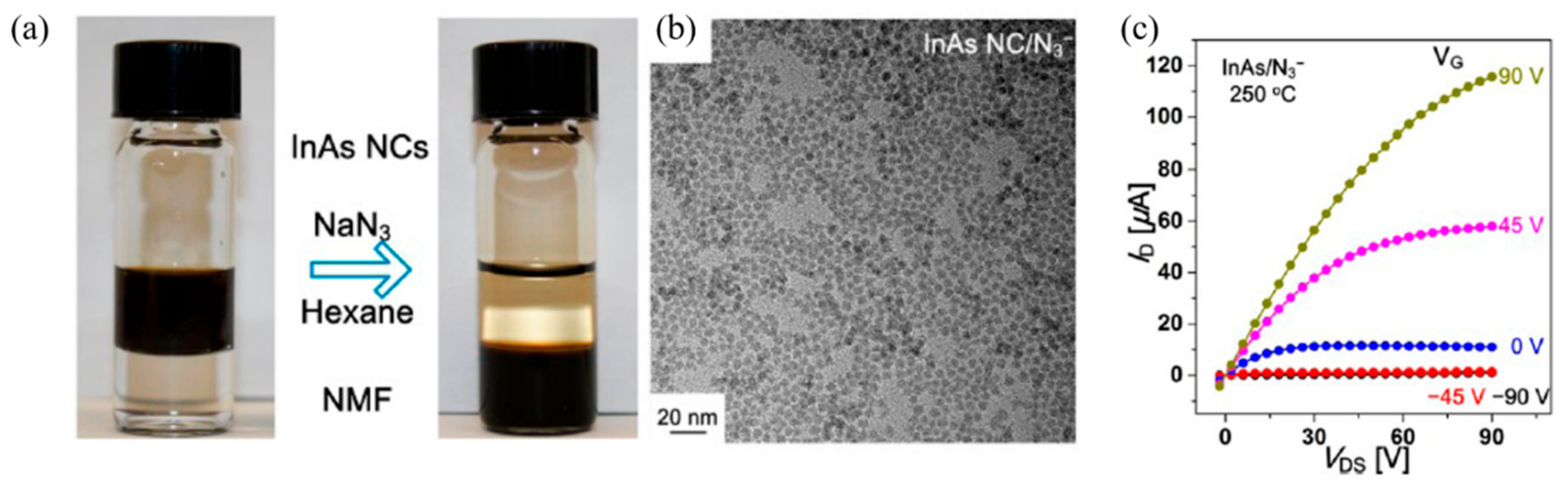
The surface chemistry related to inorganic ligands was further expanded to halide (NH4I, NH4Br, NH4Cl, and even NaCl or KBr) and even pseudohalide (e.g., N3− or CN−) ligands by Talapin’s group [80]. These short halide ligands show reduced toxicity, enhanced air/moisture stability, and higher earth abundance compared to chalcogen-based ligands. The halide anions bind to the electrophilic NC surface in polar solvents with a high dielectric constant, resulting in an electrostatically stabilized dispersion. Intriguingly, group VA ligands (azide ligands) work especially well for III–V NCs (InAs and InP), which show excellent dispersion properties in polar media, as depicted in Figure 13 [80]. The devices fabricated with N3-terminated InAs QDs show mobility (μ) of 0.16 cm2 V−1s−1 and an on–off threshold (Ion/Ioff) of ~103.
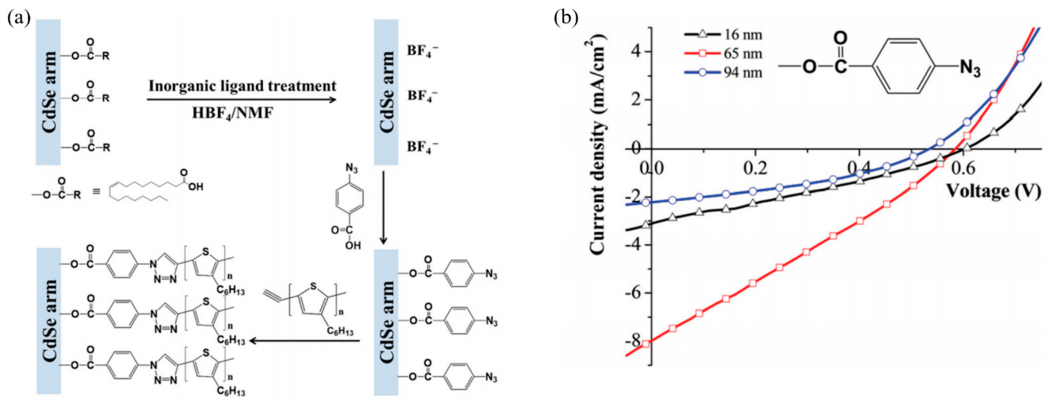
Lin et al. proposed a synthetic strategy for semiconducting organic–inorganic nanocomposites, with an inorganic ligand treatment (i.e., HBF4) [48]. In detail, the process consisted of two consecutive effective ligand exchanges (i.e., inorganic ligand treatment and subsequent bifunctional ligand exchange), followed by click coupling with end-functionalized conjugated polymers (CPs), as depicted in Figure 14 [48]. In this study, oleic acid-capped CdSe tetrapods were first subjected to a ligand exchange procedure with HBF4, producing HBF4-treated CdSe tetrapods in NMF solvent. Subsequently, bifunctional ligands (4-azidobenzoic acid and 5-bromovaleric acid) were introduced; this was followed by click coupling with ethynyl-terminated P3HT, resulting in P3HT-CdSe tetrapod nanocomposites. In this technique, effective electronic interactions at the NC-CP interface promoted interfacial charge transfer. The photovoltaic devices fabricated using P3HT-CdSe tetrapod nanocomposites showed a PCE of 1.28% with a Jsc of 7.91 mJ cm−2, Voc of 0.585 V, and FF of 27.8.
4. Summary and Outlook
In this review, we first present an overview of the methodologies in the interfacial engineering of organic–inorganic semiconductor materials based on the ligand exchange approach, direct grafting technique, in situ growth method, template strategy, and inorganic ligand surface engineering. In spite of the recent progress in designing semiconductor organic/inorganic nanocomposites, their performance in opto-electronic applications, such as LEDs, solar cells, and lasers, is still not satisfactory. The most straightforward and versatile method, the simple ligand exchange, which relies on adsorption-desorption kinetics to place functional groups on the NC surface, is not effective to detach covalently bonded ligands, i.e., X-type surfactants. Thereby, direct grafting techniques using conventional ligand refluxing often results in the existence of insulating ligand residues.
The in situ growth strategy enables a one-pot synthesis of NCs/CPs hybrid nanocomposites. Interestingly, CP-grafted NCs have been prepared via chemical coupling by in situ growth methods. It is worth noting that the CPs were grafted onto the NC surface through covalent bonding, resulting in excellent dispersion properties in organic solvents. Although this approach offers good colloidal stability as well as close contact between CPs and NCs, tailoring their morphology remains challenging.
Recent advances in surface treatment techniques enable almost complete removal of unwanted aliphatic insulating ligands. Inorganic ligands, such as molecular metal chalcogenide complexes, chalcogenide ions, and halide ligands, are generally used. This approach allows us to displace both covalently bonded ligands (i.e., X-type) and dative bonded ligands (i.e., L-type) on the NC surface, which was previously unfeasible via the conventional ligand exchange approach (e.g., pyridine and short-chain amines). It should be highlighted that the atomic-scale size of the inorganic ligands on the NC surface effectively promotes electronic interactions among NCs, as evidenced by FET mobility measurements.
Clearly, more significant efforts must be undertaken toward the design and manufacture of hybrid organic–inorganic nanocomposites, including purification, characterization, and surface treatment. The inorganic ligand treatment method is an especially active area of exploration for the preparation of novel opto-electronic building blocks.
Author Contributions
Writing—Original Draft Preparation, J.J., M.C. and H.Y.; Writing—Review & Editing, J.J., M.C. and H.Y.
Funding
This research received no external funding.
Acknowledgments
This work was supported by the National Research Foundation of Korea (NRF) grant funded by the Korea government (MSIT, Ministry of Science and ICT) (NRF-2017R1C1B5017856, NRF-2017R1C1B1004605, and NRF-2018R1A2A2A05020201).
Conflicts of Interest
The authors declare no conflict of interest.
References
- Colvin, V.L.; Schlamp, M.C.; Alivisatos, A.P. Light-emitting diodes made from cadmium selenide nanocrystals and a semiconducting polymer. Nature 1994, 370, 354–357. [Google Scholar] [CrossRef]
- Sun, Q.; Wang, Y.A.; Li, L.S.; Wang, D.; Zhu, T.; Xu, J.; Yang, C.; Li, Y. Bright, multicoloured light-emitting diodes based on quantum dots. Nat. Photon. 2007, 1, 717–722. [Google Scholar] [CrossRef]
- Huynh, W.U.; Dittmer, J.J.; Alivisatos, A.P. Hybrid nanorod-polymer solar cells. Science 2002, 295, 2425–2427. [Google Scholar] [CrossRef] [PubMed]
- Chan, W.C.W.; Nie, S. Quantum dot bioconjugates for ultrasensitive nonisotopic detection. Science 1998, 281, 2016–2018. [Google Scholar] [CrossRef] [PubMed]
- Medintz, I.L.; Uyeda, H.T.; Goldman, E.R.; Mattoussi, H. Quantum dot bioconjugates for imaging, labelling and sensing. Nat. Mater. 2005, 4, 435–446. [Google Scholar] [CrossRef] [PubMed]
- Liu, W.; Howarth, M.; Greytak, A.B.; Zheng, Y.; Nocera, D.G.; Ting, A.Y.; Bawendi, M.G. Compact biocompatible quantum dots functionalized for cellular imaging. J. Am. Chem. Soc. 2008, 130, 1274–1284. [Google Scholar] [CrossRef] [PubMed]
- Klimov, V.I.; Mikhailovsky, A.A.; Xu, S.; Malko, A.; Hollingsworth, J.A.; Leatherdale, C.A.; Eisler, H.J.; Bawendi, M.G. Optical gain and stimulated emission in nanocrystal quantum dots. Science 2000, 290, 314–317. [Google Scholar] [CrossRef] [PubMed]
- Puzder, A.; Williamson, A.J.; Zaitseva, N.; Galli, G.; Manna, L.; Alivisatos, A.P. The effect of organic ligand binding on the growth of cdse nanoparticles probed by ab initio calculations. Nano Lett. 2004, 4, 2361–2365. [Google Scholar] [CrossRef]
- Jaehan, J.; Hao, L.C.; Jun, Y.Y.; Malak, S.T.; Yaxin, Z.; Thomas, E.L.; Valy, V.; Tsukruk, V.V.; Lin, Z. Crafting core/graded shell–shell quantum dots with suppressed re-absorption and tunable stokes shift as high optical gain materials. Angew. Chem. Int. Ed. 2016, 55, 5071–5075. [Google Scholar]
- Vossmeyer, T.; Katsikas, L.; Giersig, M.; Popovic, I.G.; Diesner, K.; Chemseddine, A.; Eychmueller, A.; Weller, H. CdS nanoclusters: Synthesis, characterization, size dependent oscillator strength, temperature shift of the excitonic transition energy, and reversible absorbance shift. J. Phys. Chem. 1994, 98, 7665–7673. [Google Scholar] [CrossRef]
- Smith, A.M.; Mohs, A.M.; Nie, S. Tuning the optical and electronic properties of colloidal nanocrystals by lattice strain. Nat. Nanotechnol. 2008, 4, 56. [Google Scholar] [CrossRef] [PubMed]
- Kim, J.Y.; Lee, K.; Coates, N.E.; Moses, D.; Nguyen, T.-Q.; Dante, M.; Heeger, A.J. Efficient tandem polymer solar cells fabricated by all-solution processing. Science 2007, 317, 222–225. [Google Scholar] [CrossRef] [PubMed]
- Ma, W.; Yang, C.; Gong, X.; Lee, K.; Heeger, A.J. Thermally stable, efficient polymer solar cells with nanoscale control of the interpenetrating network morphology. Adv. Funct. Mater. 2005, 15, 1617–1622. [Google Scholar] [CrossRef]
- Le, T.-H.; Kim, Y.; Yoon, H. Electrical and electrochemical properties of conducting polymers. Polymers 2017, 9, 150. [Google Scholar] [CrossRef]
- Kong, H.J.; Kim, S.; Le, T.-H.; Kim, Y.; Park, G.; Park, C.S.; Kwon, O.S.; Yoon, H. Nanostructured mesophase electrode materials: Modulating charge-storage behavior by thermal treatment. Nanoscale 2017, 9, 17450–17458. [Google Scholar] [CrossRef] [PubMed]
- Shrotriya, V.; Wu, E.H.E.; Li, G.; Yao, Y.; Yang, Y. Efficient light harvesting in multiple-device stacked structure for polymer solar cells. Appl. Phys. Lett. 2006, 88, 064104. [Google Scholar] [CrossRef]
- Kalyuzhny, G.; Murray, R.W. Ligand effects on optical properties of CdSe nanocrystals. J. Phys. Chem. B 2005, 109, 7012–7021. [Google Scholar] [CrossRef] [PubMed]
- Munro, A.M.; Jen-La Plante, I.; Ng, M.S.; Ginger, D.S. Quantitative study of the effects of surface ligand concentration on CdSe nanocrystal photoluminescence. J. Phys. Chem. C 2007, 111, 6220–6227. [Google Scholar] [CrossRef]
- Janssen, R.A.J.; Nelson, J. Factors limiting device efficiency in organic photovoltaics. Adv. Mater. 2013, 25, 1847–1858. [Google Scholar] [CrossRef] [PubMed]
- Reiss, P.; Couderc, E.; De Girolamo, J.; Pron, A. Conjugated polymers/semiconductor nanocrystals hybrid materials-preparation, electrical transport properties and applications. Nanoscale 2011, 3, 446–489. [Google Scholar] [CrossRef] [PubMed]
- Glatthaar, M.; Riede, M.; Keegan, N.; Sylvester-Hvid, K.; Zimmermann, B.; Niggemann, M.; Hinsch, A.; Gombert, A. Efficiency limiting factors of organic bulk heterojunction solar cells identified by electrical impedance spectroscopy. Sol. Energy Mater. Sol. Cells 2007, 91, 390–393. [Google Scholar] [CrossRef]
- Heinemann, M.D.; von Maydell, K.; Zutz, F.; Kolny-Olesiak, J.; Borchert, H.; Riedel, I.; Parisi, J. Photo-induced charge transfer and relaxation of persistent charge carriers in polymer/nanocrystal composites for applications in hybrid solar cells. Adv. Funct. Mater. 2009, 19, 3788–3795. [Google Scholar] [CrossRef]
- Jung, J.; Yoon, Y.J.; Lin, Z. Intimate organic-inorganic nanocomposites via rationally designed conjugated polymer-grafted precursors. Nanoscale 2016, 8, 16520–16527. [Google Scholar] [CrossRef] [PubMed]
- Xu, J.; Wang, J.; Mitchell, M.; Mukherjee, P.; Jeffries-El, M.; Petrich, J.W.; Lin, Z. Organic−inorganic nanocomposites via directly grafting conjugated polymers onto quantum dots. J. Am. Chem. Soc. 2007, 129, 12828–12833. [Google Scholar] [CrossRef] [PubMed]
- Zhao, L.; Pang, X.; Adhikary, R.; Petrich, J.W.; Jeffries-El, M.; Lin, Z. Organic−inorganic nanocomposites by placing conjugated polymers in intimate contact with quantum rods. Adv. Mater. 2011, 23, 2844–2849. [Google Scholar] [CrossRef] [PubMed]
- Jung, J.; Pang, X.; Feng, C.; Lin, Z. Semiconducting conjugated polymer–inorganic tetrapod nanocomposites. Langmuir 2013, 29, 8086–8092. [Google Scholar] [CrossRef] [PubMed]
- Liao, H.-C.; Chen, S.-Y.; Liu, D.-M. In-situ growing CdS single-crystal nanorods via P3HT polymer as a soft template for enhancing photovoltaic performance. Macromolecules 2009, 42, 6558–6563. [Google Scholar] [CrossRef]
- Zhao, L.; Lin, Z. Crafting semiconductor organic–inorganic nanocomposites via placing conjugated polymers in intimate contact with nanocrystals for hybrid solar cells. Adv. Mater. 2012, 24, 4353–4368. [Google Scholar] [CrossRef] [PubMed]
- Ning, Z.; Voznyy, O.; Pan, J.; Hoogland, S.; Adinolfi, V.; Xu, J.; Li, M.; Kirmani, A.R.; Sun, J.-P.; Minor, J.; et al. Air-stable n-type colloidal quantum dot solids. Nat. Mater. 2014, 13, 822–828. [Google Scholar] [CrossRef] [PubMed]
- Querner, C.; Benedetto, A.; Demadrille, R.; Rannou, P.; Reiss, P. Carbodithioate-containing oligo- and polythiophenes for nanocrystals’ surface functionalization. Chem. Mater. 2006, 18, 4817–4826. [Google Scholar] [CrossRef]
- Green, M.L.H.; Parkin, G. Application of the covalent bond classification method for the teaching of inorganic chemistry. J. Chem. Educ. 2014, 91, 807–816. [Google Scholar] [CrossRef]
- Anderson, N.C.; Hendricks, M.P.; Choi, J.J.; Owen, J.S. Ligand exchange and the stoichiometry of metal chalcogenide nanocrystals: Spectroscopic observation of facile metal-carboxylate displacement and binding. J. Am. Chem. Soc. 2013, 135, 18536–18548. [Google Scholar] [CrossRef] [PubMed]
- Owen, J.S.; Park, J.; Trudeau, P.-E.; Alivisatos, A.P. Reaction chemistry and ligand exchange at cadmium−selenide nanocrystal surfaces. J. Am. Chem. Soc. 2008, 130, 12279–12281. [Google Scholar] [CrossRef] [PubMed]
- Murray, C.B.; Norris, D.J.; Bawendi, M.G. Synthesis and characterization of nearly monodisperse CdE (E = sulfur, selenium, tellurium) semiconductor nanocrystallites. J. Am. Chem. Soc. 1993, 115, 8706–8715. [Google Scholar] [CrossRef]
- Akdas, T.; Walter, J.; Segets, D.; Distaso, M.; Winter, B.; Birajdar, B.; Spiecker, E.; Peukert, W. Investigation of the size-property relationship in CuInS2 quantum dots. Nanoscale 2015, 7, 18105–18118. [Google Scholar] [CrossRef] [PubMed]
- Li, Z.; Ji, Y.; Xie, R.; Grisham, S.Y.; Peng, X. Correlation of CdS nanocrystal formation with elemental sulfur activation and its implication in synthetic development. J. Am. Chem. Soc. 2011, 133, 17248–17256. [Google Scholar] [CrossRef] [PubMed]
- Cros-Gagneux, A.; Delpech, F.; Nayral, C.; Cornejo, A.; Coppel, Y.; Chaudret, B. Surface chemistry of InP quantum dots: A comprehensive study. J. Am. Chem. Soc. 2010, 132, 18147–18157. [Google Scholar] [CrossRef] [PubMed]
- Nan, W.; Niu, Y.; Qin, H.; Cui, F.; Yang, Y.; Lai, R.; Lin, W.; Peng, X. Crystal structure control of zinc-blende CdSe/CdS core/shell nanocrystals: Synthesis and structure-dependent optical properties. J. Am. Chem. Soc. 2012, 134, 19685–19693. [Google Scholar] [CrossRef] [PubMed]
- Gaponik, N.; Talapin, D.V.; Rogach, A.L.; Hoppe, K.; Shevchenko, E.V.; Kornowski, A.; Eychmüller, A.; Weller, H. Thiol-capping of CdTe nanocrystals: An alternative to organometallic synthetic routes. J. Phys. Chem. B 2002, 106, 7177–7185. [Google Scholar] [CrossRef]
- William, Y.W.; Xiaogang, P. Formation of high-quality CdS and other II–VI semiconductor nanocrystals in noncoordinating solvents: Tunable reactivity of monomers. Angew. Chem. Int. Ed. 2002, 41, 2368–2371. [Google Scholar]
- Hassinen, A.; Moreels, I.; De Nolf, K.; Smet, P.F.; Martins, J.C.; Hens, Z. Short-chain alcohols strip X-type ligands and quench the luminescence of PbSe and CdSe quantum dots, acetonitrile does not. J. Am. Chem. Soc. 2012, 134, 20705–20712. [Google Scholar] [CrossRef] [PubMed]
- Morris-Cohen, A.J.; Donakowski, M.D.; Knowles, K.E.; Weiss, E.A. The effect of a common purification procedure on the chemical composition of the surfaces of CdSe quantum dots synthesized with trioctylphosphine oxide. J. Phys. Chem. C 2010, 114, 897–906. [Google Scholar] [CrossRef]
- Jasieniak, J.; Mulvaney, P. From Cd-rich to Se-rich—The manipulation of CdSe nanocrystal surface stoichiometry. J. Am. Chem. Soc. 2007, 129, 2841–2848. [Google Scholar] [CrossRef] [PubMed]
- Fritzinger, B.; Moreels, I.; Lommens, P.; Koole, R.; Hens, Z.; Martins, J.C. In situ observation of rapid ligand exchange in colloidal nanocrystal suspensions using transfer NOE nuclear magnetic resonance spectroscopy. J. Am. Chem. Soc. 2009, 131, 3024–3032. [Google Scholar] [CrossRef] [PubMed]
- Cass, L.C.; Malicki, M.; Weiss, E.A. The chemical environments of oleate species within samples of oleate-coated PbS quantum dots. Anal. Chem. 2013, 85, 6974–6979. [Google Scholar] [CrossRef] [PubMed]
- Maes, J.; Castro, N.; De Nolf, K.; Walravens, W.; Abécassis, B.; Hens, Z. Size and concentration determination of colloidal nanocrystals by small-angle X-ray scattering. Chem. Mater. 2018, 30, 3952–3962. [Google Scholar] [CrossRef]
- Yu, W.W.; Qu, L.; Guo, W.; Peng, X. Experimental determination of the extinction coefficient of CdTe, CdSe, and CdS nanocrystals. Chem. Mater. 2003, 15, 2854–2860. [Google Scholar] [CrossRef]
- Jung, J.; Yoon, Y.J.; Lin, Z. Semiconducting organic-inorganic nanocomposites by intimately tethering conjugated polymers to inorganic tetrapods. Nanoscale 2016, 8, 8887–8898. [Google Scholar] [CrossRef] [PubMed]
- Luo, X.; Liu, P.; Truong, N.T.N.; Farva, U.; Park, C. Photoluminescence blue-shift of CdSe nanoparticles caused by exchange of surface capping layer. J. Phys. Chem. C 2011, 115, 20817–20823. [Google Scholar] [CrossRef]
- Liu, L.; Peng, Q.; Li, Y. An effective oxidation route to blue emission CdSe quantum dots. Inorg. Chem. 2008, 47, 3182–3187. [Google Scholar] [CrossRef] [PubMed]
- Cho, J.; Jung, Y.K.; Lee, J.-K.; Jung, H.-S. Highly efficient blue-emitting CdSe-derived core/shell gradient alloy quantum dots with improved photoluminescent quantum yield and enhanced photostability. Langmuir 2017, 33, 3711–3719. [Google Scholar] [CrossRef] [PubMed]
- Virieux, H.; Le Troedec, M.; Cros-Gagneux, A.; Ojo, W.-S.; Delpech, F.; Nayral, C.; Martinez, H.; Chaudret, B. InP/ZnS nanocrystals: Coupling NMR and XPS for fine surface and interface description. J. Am. Chem. Soc. 2012, 134, 19701–19708. [Google Scholar] [CrossRef] [PubMed]
- Zeger, H.; Moreels, I.; Martins, J.C. In situ 1H NMR study on the trioctylphosphine oxide capping of colloidal InP nanocrystals. ChemPhysChem 2005, 6, 2578–2584. [Google Scholar]
- Xie, L.; Shen, Y.; Franke, D.; Sebastián, V.; Bawendi, M.G.; Jensen, K.F. Characterization of indium phosphide quantum dot growth intermediates using Maldi-TOF mass spectrometry. J. Am. Chem. Soc. 2016, 138, 13469–13472. [Google Scholar] [CrossRef] [PubMed]
- Gomes, R.; Hassinen, A.; Szczygiel, A.; Zhao, Q.; Vantomme, A.; Martins, J.C.; Hens, Z. Binding of phosphonic acids to CdSe quantum dots: A solution NMR study. J. Phys. Chem. Lett. 2011, 2, 145–152. [Google Scholar] [CrossRef]
- Anderson, N.C.; Owen, J.S. Soluble, chloride-terminated CdSe nanocrystals: Ligand exchange monitored by 1H and 31P NMR spectroscopy. Chem. Mater. 2013, 25, 69–76. [Google Scholar] [CrossRef]
- Zhang, Y.; Fry, C.G.; Pedersen, J.A.; Hamers, R.J. Dynamics and morphology of nanoparticle-linked polymers elucidated by nuclear magnetic resonance. Anal. Chem. 2017, 89, 12399–12407. [Google Scholar] [CrossRef] [PubMed]
- Drijvers, E.; De Roo, J.; Martins, J.C.; Infante, I.; Hens, Z. Ligand displacement exposes binding site heterogeneity on CdSe nanocrystal surfaces. Chem. Mater. 2018, 30, 1178–1186. [Google Scholar] [CrossRef]
- Fritzinger, B.; Capek, R.K.; Lambert, K.; Martins, J.C.; Hens, Z. Utilizing self-exchange to address the binding of carboxylic acid ligands to CdSe quantum dots. J. Am. Chem. Soc. 2010, 132, 10195–10201. [Google Scholar] [CrossRef] [PubMed]
- Knittel, F.; Gravel, E.; Cassette, E.; Pons, T.; Pillon, F.; Dubertret, B.; Doris, E. On the characterization of the surface chemistry of quantum dots. Nano Lett. 2013, 13, 5075–5078. [Google Scholar] [CrossRef] [PubMed]
- Rajh, T.; Micic, O.I.; Nozik, A.J. Synthesis and characterization of surface-modified colloidal cadmium telluride quantum dots. J. Phys. Chem. 1993, 97, 11999–12003. [Google Scholar] [CrossRef]
- Yu, P.; Beard, M.C.; Ellingson, R.J.; Ferrere, S.; Curtis, C.; Drexler, J.; Luiszer, F.; Nozik, A.J. Absorption cross-section and related optical properties of colloidal inas quantum dots. J. Phys. Chem. B 2005, 109, 7084–7087. [Google Scholar] [CrossRef] [PubMed]
- Soloviev, V.N.; Eichhöfer, A.; Fenske, D.; Banin, U. Molecular limit of a bulk semiconductor: Size dependence of the “band gap” in cdse cluster molecules. J. Am. Chem. Soc. 2000, 122, 2673–2674. [Google Scholar] [CrossRef]
- Leatherdale, C.A.; Woo, W.K.; Mikulec, F.V.; Bawendi, M.G. On the absorption cross section of CdSe nanocrystal quantum dots. J. Phys. Chem. B 2002, 106, 7619–7622. [Google Scholar] [CrossRef]
- Zhang, Q.; Russell, T.P.; Emrick, T. Synthesis and characterization of CdSe nanorods functionalized with regioregular poly(3-hexylthiophene). Chem. Mater. 2007, 19, 3712–3716. [Google Scholar] [CrossRef]
- Yang, Y.; Qin, H.; Jiang, M.; Lin, L.; Fu, T.; Dai, X.; Zhang, Z.; Niu, Y.; Cao, H.; Jin, Y.; et al. Entropic ligands for nanocrystals: From unexpected solution properties to outstanding processability. Nano Lett. 2016, 16, 2133–2138. [Google Scholar] [CrossRef] [PubMed]
- Dayal, S.; Kopidakis, N.; Olson, D.C.; Ginley, D.S.; Rumbles, G. Direct synthesis of CdSe nanoparticles in poly(3-hexylthiophene). J. Am. Chem. Soc. 2009, 131, 17726–17727. [Google Scholar] [CrossRef] [PubMed]
- Khan, M.T.; Kaur, A.; Dhawan, S.K.; Chand, S. In-situ growth of cadmium telluride nanocrystals in poly(3-hexylthiophene) matrix for photovoltaic application. J. Appl. Phys. 2011, 110, 044509. [Google Scholar] [CrossRef]
- Chen, Y.; Wang, Z.; He, Y.; Yoon, Y.J.; Jung, J.; Zhang, G.; Lin, Z. Light-enabled reversible self-assembly and tunable optical properties of stable hairy nanoparticles. Proc. Natl. Acad. Sci. USA 2018, 115, E1391–E1400. [Google Scholar] [CrossRef] [PubMed]
- Chen, Y.; Yang, D.; Yoon, Y.J.; Pang, X.; Wang, Z.; Jung, J.; He, Y.; Harn, Y.W.; He, M.; Zhang, S.; et al. Hairy uniform permanently ligated hollow nanoparticles with precise dimension control and tunable optical properties. J. Am. Chem. Soc. 2017, 139, 12956–12967. [Google Scholar] [CrossRef] [PubMed]
- Pang, X.; Zhao, L.; Han, W.; Xin, X.; Lin, Z. A general and robust strategy for the synthesis of nearly monodisperse colloidal nanocrystals. Nat. Nanotechnol. 2013, 8, 426. [Google Scholar] [CrossRef] [PubMed]
- Kovalenko, M.V.; Scheele, M.; Talapin, D.V. Colloidal nanocrystals with molecular metal chalcogenide surface ligands. Science 2009, 324, 1417–1420. [Google Scholar] [CrossRef] [PubMed]
- Choi, S.; Jin, H.; Kim, S. Sns44– metal chalcogenide ligand, s2– metal free ligand, and organic surface ligand toward efficient cdse quantum dot- sensitized solar cells. J. Phys. Chem. C 2014, 118, 17019–17027. [Google Scholar] [CrossRef]
- Kovalenko, M.V.; Bodnarchuk, M.I.; Zaumseil, J.; Lee, J.-S.; Talapin, D.V. Expanding the chemical versatility of colloidal nanocrystals capped with molecular metal chalcogenide ligands. J. Am. Chem. Soc. 2010, 132, 10085–10092. [Google Scholar] [CrossRef] [PubMed]
- Jin, H.; Choi, S.; Xing, G.; Lee, J.-H.; Kwon, Y.; Chong, W.K.; Sum, T.C.; Jang, H.M.; Kim, S. SnS44–, SbS43–, and AsS33– metal chalcogenide surface ligands: Couplings to quantum dots, electron transfers, and all-inorganic multilayered quantum dot sensitized solar cells. J. Am. Chem. Soc. 2015, 137, 13827–13835. [Google Scholar] [CrossRef] [PubMed]
- Ren, Z.; Yu, J.; Pan, Z.; Wang, J.; Zhong, X. Inorganic ligand thiosulfate-capped quantum dots for efficient quantum dot sensitized solar cells. ACS Appl. Mater. Interfaces 2017, 9, 18936–18944. [Google Scholar] [CrossRef] [PubMed]
- Dong, A.; Ye, X.; Chen, J.; Kang, Y.; Gordon, T.; Kikkawa, J.M.; Murray, C.B. A generalized ligand-exchange strategy enabling sequential surface functionalization of colloidal nanocrystals. J. Am. Chem. Soc. 2011, 133, 998–1006. [Google Scholar] [CrossRef] [PubMed]
- Nag, A.; Kovalenko, M.V.; Lee, J.-S.; Liu, W.; Spokoyny, B.; Talapin, D.V. Metal-free inorganic ligands for colloidal nanocrystals: S2−, HS−, Se2−, HSe−, Te2−, HTe−, TeS32−, OH−, and NH2− as surface ligands. J. Am. Chem. Soc. 2011, 133, 10612–10620. [Google Scholar] [CrossRef] [PubMed]
- Fafarman, A.T.; Koh, W.-k.; Diroll, B.T.; Kim, D.K.; Ko, D.-K.; Oh, S.J.; Ye, X.; Doan-Nguyen, V.; Crump, M.R.; Reifsnyder, D.C.; et al. Thiocyanate-capped nanocrystal colloids: Vibrational reporter of surface chemistry and solution-based route to enhanced coupling in nanocrystal solids. J. Am. Chem. Soc. 2011, 133, 15753–15761. [Google Scholar] [CrossRef] [PubMed]
- Zhang, H.; Jang, J.; Liu, W.; Talapin, D.V. Colloidal nanocrystals with inorganic halide, pseudohalide, and halometallate ligands. ACS Nano 2014, 8, 7359–7369. [Google Scholar] [CrossRef] [PubMed]
Figure 1.
Classification of the bonding nature of ligands. Reprinted with permission from [32]. Copyright 2013, American Chemical Society.
Figure 1.
Classification of the bonding nature of ligands. Reprinted with permission from [32]. Copyright 2013, American Chemical Society.

Figure 2.
Absorption spectra for the separation of CdS nanocrystals from cadmium oleate and oleic acid. Reprinted with permission from [40]. Copyright 2002, John Wiley & Sons.
Figure 2.
Absorption spectra for the separation of CdS nanocrystals from cadmium oleate and oleic acid. Reprinted with permission from [40]. Copyright 2002, John Wiley & Sons.

Figure 3.
Alkene region of the proton NMR spectra after precipitation/resuspension with (a) methanol and (b) acetonitrile. Photoluminescence characterization of CdSe QDs after purification with (c) methanol and (d) acetonitrile. Reprinted with permission from [33]. Copyright 2012, American Chemical Society.

Figure 4.
1H NMR spectrum of (a) free-state OA and (b) OA-capped CdSe QDs. Change in alkene resonance upon addition of (c) free OA and (d) deuterated OA. Reprinted with permission from [59]. Copyright 2012, American Chemical Society.
Figure 4.
1H NMR spectrum of (a) free-state OA and (b) OA-capped CdSe QDs. Change in alkene resonance upon addition of (c) free OA and (d) deuterated OA. Reprinted with permission from [59]. Copyright 2012, American Chemical Society.

Figure 5.
(a) Synthetic route to form 3H-labeled OA ligands; (b) relative OA detachment strengths of the different ligands. Reprinted with permission from [60]. Copyright 2013, American Chemical Society.
Figure 5.
(a) Synthetic route to form 3H-labeled OA ligands; (b) relative OA detachment strengths of the different ligands. Reprinted with permission from [60]. Copyright 2013, American Chemical Society.

Figure 6.
(a) Size curves vs. the first absorption peak position; (b) size-dependent molar absorption coefficients of nanocrystals at the first excitonic absorption. Reprinted with permission from [47]. Copyright 2003, American Chemical Society.
Figure 6.
(a) Size curves vs. the first absorption peak position; (b) size-dependent molar absorption coefficients of nanocrystals at the first excitonic absorption. Reprinted with permission from [47]. Copyright 2003, American Chemical Society.

Figure 7.
Schematic illustration of ligand exchange and grafting of end-functionalized CPs onto NCs. Reprinted with permission from [24]. Copyright 2007 American Chemical Society.
Figure 7.
Schematic illustration of ligand exchange and grafting of end-functionalized CPs onto NCs. Reprinted with permission from [24]. Copyright 2007 American Chemical Society.

Figure 8.
Schematic illustration of the growth mechanism of CdS NCs in the presence of P3HT. Reprinted with permission from [27]. Copyright 2009, American Chemical Society.
Figure 8.
Schematic illustration of the growth mechanism of CdS NCs in the presence of P3HT. Reprinted with permission from [27]. Copyright 2009, American Chemical Society.

Figure 9.
Formation of P3HT-CdSe QD nanocomposites via in situ growth. Reprinted with permission from [23]. Copyright 2016, Royal Society of Chemistry.
Figure 9.
Formation of P3HT-CdSe QD nanocomposites via in situ growth. Reprinted with permission from [23]. Copyright 2016, Royal Society of Chemistry.

Figure 10.
Schematic illustration of the formation of hybrid nanocomposites using a template. Reprinted with permission from [71]. Copyright 2013, Springer Nature.
Figure 10.
Schematic illustration of the formation of hybrid nanocomposites using a template. Reprinted with permission from [71]. Copyright 2013, Springer Nature.

Figure 11.
Scheme of a CdSe QD-sensitized solar cell (QDSC) and J-V curves for oleylamine, S2−, and S2O32−-capped CdSe QDs-based QDSCs (FTO is fluorine-doped tin oxide glass). Reprinted with permission from [76]. Copyright 2017, American Chemical Society.
Figure 11.
Scheme of a CdSe QD-sensitized solar cell (QDSC) and J-V curves for oleylamine, S2−, and S2O32−-capped CdSe QDs-based QDSCs (FTO is fluorine-doped tin oxide glass). Reprinted with permission from [76]. Copyright 2017, American Chemical Society.

Figure 12.
Schematic illustration of the secondary ligand exchange procedure and the corresponding FTIR spectra. Reprinted with permission from [77]. Copyright 2009, American Chemical Society.
Figure 12.
Schematic illustration of the secondary ligand exchange procedure and the corresponding FTIR spectra. Reprinted with permission from [77]. Copyright 2009, American Chemical Society.

Figure 13.
(a) Digital image of InAs NCs before and after NaN3 treatment; (b) TEM image of InAs NCs capped with N3−; (c) Plot of I/V measurement of N3-capped InAs NCs FET devices. Reprinted with permission from [80]. Copyright 2014, American Chemical Society.
Figure 13.
(a) Digital image of InAs NCs before and after NaN3 treatment; (b) TEM image of InAs NCs capped with N3−; (c) Plot of I/V measurement of N3-capped InAs NCs FET devices. Reprinted with permission from [80]. Copyright 2014, American Chemical Society.

Figure 14.
(a) Illustration of the formation of P3HT-CdSe tetrapod nanocomposites; (b) current–voltage plot of hybrid solar cells. Reprinted with permission from [48]. Copyright 2016, Royal Society of Chemistry.
Figure 14.
(a) Illustration of the formation of P3HT-CdSe tetrapod nanocomposites; (b) current–voltage plot of hybrid solar cells. Reprinted with permission from [48]. Copyright 2016, Royal Society of Chemistry.


Table 1.
Optical properties and diameters of CdS, CdSe, and CdTe QDs.
| Materials | Diameter (nm) | Molar Absorption Coefficient |
|---|---|---|
| CdS | ||
| CdSe | ||
| CdTe |
© 2018 by the authors. Licensee MDPI, Basel, Switzerland. This article is an open access article distributed under the terms and conditions of the Creative Commons Attribution (CC BY) license (http://creativecommons.org/licenses/by/4.0/).
Share and Cite
MDPI and ACS Style
Jung, J.; Chang, M.; Yoon, H. Interface Engineering Strategies for Fabricating Nanocrystal-Based Organic–Inorganic Nanocomposites. Appl. Sci. 2018, 8, 1376. https://doi.org/10.3390/app8081376
AMA Style
Jung J, Chang M, Yoon H. Interface Engineering Strategies for Fabricating Nanocrystal-Based Organic–Inorganic Nanocomposites. Applied Sciences. 2018; 8(8):1376. https://doi.org/10.3390/app8081376
Chicago/Turabian StyleJung, Jaehan, Mincheol Chang, and Hyeonseok Yoon. 2018. "Interface Engineering Strategies for Fabricating Nanocrystal-Based Organic–Inorganic Nanocomposites" Applied Sciences 8, no. 8: 1376. https://doi.org/10.3390/app8081376
Note that from the first issue of 2016, this journal uses article numbers instead of page numbers. See further details here.