Article

Scaffolds with a High Surface Area-to-Volume Ratio and Cultured Under Fast Flow Perfusion Result in Optimal O2 Delivery to the Cells in Artificial Bone Tissues

by
Thanh Danh Nguyen
1,
Olufemi E. Kadri
1,
Vassilios I. Sikavitsas
2 and
Roman S. Voronov
1,*
1
Otto H. York Department of Chemical and Materials Engineering, New Jersey Institute of Technology, Newark, NJ 07102, USA
2
School of Chemical, Biological and Materials Engineering, University of Oklahoma Norman, OK 73019, USA
*
Author to whom correspondence should be addressed.
Appl. Sci. 2019, 9(11), 2381; https://doi.org/10.3390/app9112381
Submission received: 1 May 2019 / Revised: 1 June 2019 / Accepted: 7 June 2019 / Published: 11 June 2019
(This article belongs to the Special Issue Biomaterials for Bone Tissue Engineering)

Abstract

:

Featured Application

Optimization of Scaffold Design and Flow Perfusion Culturing Conditions for Maximal Delivery of Oxygen to the Cells Embedded Deep Inside of Engineered Tissues.

Abstract

Tissue engineering has the potential for repairing large bone defects, which impose a heavy financial burden on the public health. However, difficulties with O2 delivery to the cells residing in the interior of tissue engineering scaffolds make it challenging to grow artificial tissues of clinically-relevant sizes. This study uses image-based simulation in order to provide insight into how to better optimize the scaffold manufacturing parameters, and the culturing conditions, in order to resolve the O2 bottleneck. To do this, high resolution 3D X-ray images of two common scaffold types (salt leached foam and non-woven fiber mesh) are fed into Lattice Boltzmann Method fluid dynamics and reactive Lagrangian Scalar Tracking mass transfer solvers. The obtained findings indicate that the scaffolds should have maximal surface area-to-solid volume ratios for higher chances of the molecular collisions with the cells. Furthermore, the cell culture media should be flown through the scaffold pores as fast as practically possible (without detaching or killing the cells). Finally, we have provided a parametric sweep that maps how the molecular transport within the scaffolds is affected by variations in rates of O2 consumption by the cells. Ultimately, the results of this study are expected to benefit the computer-assisted design of tissue engineering scaffolds and culturing experiments.

1. Introduction

Incidences of bone disorders constitute a significant economic burden to societies globally. In the United States alone, the total annual cost (direct and indirect) of treating an estimated 126.6 million people affected by musculoskeletal disorders exceeds $213 billion [1]. Moreover, with an increasingly obese and ageing population, this trend is expected to continue further. Unfortunately, according to U.S Department of Health & Human Services, only ~10% out of the 115,000 people who needed a lifesaving organ transplant in 2018 have actually received it. This is because despite the overwhelming demand, almost no FDA approved [2] artificial tissue products are commercially available today.
A major hurdle standing in the way of producing viable engineered bone is product size limitations. These in turn stem from the inability to deliver sufficient amounts of metabolites (e.g., O2, nutrients, etc.) to the inner pore spaces of scaffolds, given that the cells consume them in large quantities as they build tissue. Among these, O2 plays a critical role in the cell growth and proliferation, and thus its high concentrations have been correlated with both increased cellularity [3] and cell viability [4]. Conversely, a deficiency in O2 can result in a hypoxic cell state, which is commonly associated with decreased metabolic activity and potentially undesirable differentiation behavior [5,6,7]. Hence, optimal oxygen transport is important in maintaining tissue function and overall survival within the artificial tissues. For that reason, bone tissue engineering scaffolds are typically cultured in perfusion bioreactors, the idea behind which is to facilitate the mass transfer using flow.
However, understanding what scaffold fabrication parameters and flow culturing conditions result in the optimal O2 delivery to the cells is made difficult by the complexity of the pore network architectures in which they reside. This is because most large scaffolds are not transparent enough for microscopy, and it is also difficult to measure the O2 concentrations at different locations within the scaffolds. Furthermore, the O2 uptake rate by the cells changes over time [3]. All these complications make the problem even more difficult to solve manually. For these reasons, computer simulation of the O2 transport and consumption offers itself as a viable alternative for obtaining insight into the microenvironment, which is experienced by the cells seeded on the surfaces of the scaffold pores.
Yet, modeling of mass transport (and specifically of O2) within scaffolds is uncommon when compared to flow parameters, such as stimulatory fluid shear stress, permeability, and pressure (see Table II in Ref. [8]). Furthermore, Table 1 below summarizes our overview of the few O2 models that we did find in literature. From it, it can be seen that the studies commonly use idealized geometries for the scaffolds (e.g., a homogeneous porous medium) instead of realistic image-based. In reality, however, the scaffold architectures may be inhomogeneous. Moreover, many of the models either do not take into account specificities of bone tissue engineering, such as the need for flow perfusion, which generates a stimulatory shear environment natural to the bone canaliculi [9,10]. Instead, many models either target tissue engineering in general, or they may be specific to other tissue engineering disciplines; for example, Ferroni et al. [11] modeled a cardiac scaffold, which is cultured under pulsatile flow (not the case for bone). Finally, few of the models take into account O2 consumption by the cells. And among those that do, the rate is typically assumed to be constant. Thus, we were not able to find a single bone tissue engineering model that accounted for all of the following: the realistic scaffold structure, O2 diffusion, convection, and variable consumption rates.
Therefore, in this work we aim to shed insight on how scaffold manufacturing parameters and flow culturing conditions affect the O2 transport and uptake by the cells in realistic bone tissue engineering scaffolds. To do this, we use two types of commonly-implemented types: the salt leached foam and the non-woven fiber mesh poly-L-lactic acid (PLLA) scaffolds. Their geometries are scanned in 3D using high resolution micro-computed tomography (µCT), and are imported into our image-based Lattice Boltzmann Method (LBM) flow [16,17,18,19] and reactive Lagrangian Scalar Tracking (rLST) mass transport [20] solvers. A big advantage of the latter is it can model particles with a range of reactivity, which is informative about how cells that are not necessarily starved for O2 consume it. In this way, a more complete picture of O2 transport within the different types of BTE scaffolds can be constructed. The overall computational scheme is depicted in Figure 1.

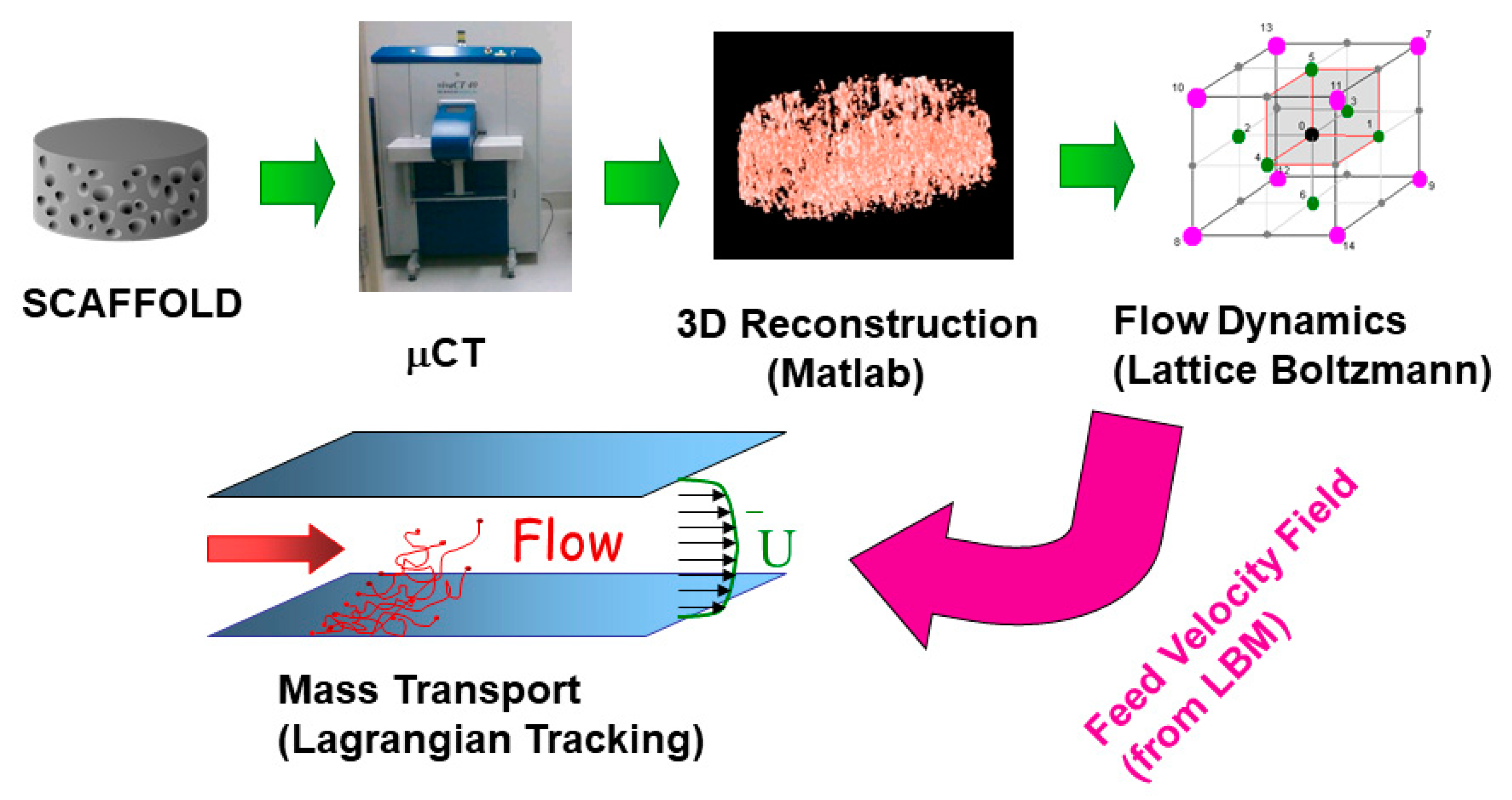
2. Materials and Methods

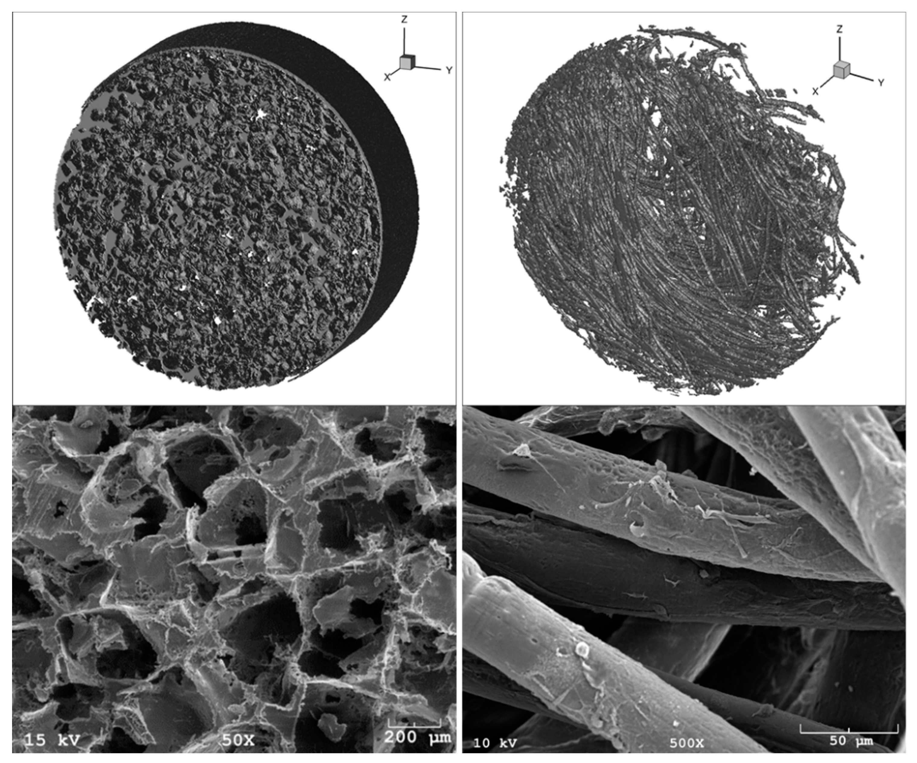
2.1. Scaffold Fabrication

The full details of the scaffold preparation protocols can be found in our previous publications [16,17]. Briefly, the scaffolds were non-woven fiber meshes constructed using polymer micro-fibers produced with spunbonding. The polymer used in the production of fibers was poly-L-lactic-acid (grade 6251D, 1.4% D enantiomer 108,500 MW, 1.87 PDI, NatureWorks LLC). A custom Brabender extruder (19.1 mm (0.75 in.) diameter × 381 mm length) was used to pressurize and melt the polymer. A manually circulated collection screen was used to collect a random even layering of fibers. Layers of fibers were stacked and measured until the stack reached a mass of 9.0 ± 0.1 g within an area of 162.8 cm2. The collected non-woven fiber stack then had a 7 cm center cut sheet obtained from it. Finally, using an 8 mm diameter die, discs were punched from the layered fiber sheets. The resulting scaffolds used in culturing were 8 mm diameter and ~2.3 mm thickness. Average fiber diameter was measured optically, using a Nikon HFX-II microscope.
The porous foam scaffolds were prepared using solvent casting/particulate leaching method [21,22,23,24]. Briefly, poly-L-lactic acid (PLLA, 114,500 MW, 1.87 PDI, Birmingham Polymers) was dissolved into chloroform 5% w/v. The solution was then poured over a bed of sodium chloride crystals. Solvent was allowed to evaporate for 24 h. The resulting salt-polymer composite was inserted into an 8 mm diameter cylindrical mold and compressed at 500 psi. During compression, the composite was heated to 130 °C and held at constant temperature and pressure for 30 min. Using a diamond wheel saw (Model 650, South Bay Technology, Inc.), the resulting composite rod was cut into 2.3 mm thick discs. The discs were placed into deionized water (DIH2O) under agitation for 2 days to leach out NaCl. Entire DIH2O volumes were replaced twice per day. Leached discs were then removed from DIH2O and placed under vacuum to remove moisture from the scaffolds. The resulting products were 8 mm diameter, 2.3 mm thick discs. Porosity of scaffolds was determined by measuring the solid volume (mass of the scaffold divided by the density of PLLA) and by comparing it to the total scaffold volume (assuming a cylindrical scaffold shape).

2.2. 3D Imaging and Virtual Reconstruction

The full details of our scanning procedure can be found in our previous publication [16,17,25]. Briefly, scaffolds were then scanned via µCT using a ScanCo VivaCT40 system (ScanCo Medical, Bassersdorf, Switzerland) to obtain 10 µm resolution, 2D intensity image slices at the optimum settings of 88 µA (intensity), and 45 kV (energy). The acquired X-ray images were filtered for noise reduction and assembled into 3D reconstructions of the scaffolds using a custom Matlab code (MathWorks Inc., Natick, MA). The scans were segmented using global thresholding. Threshold values were chosen such that the porosity of scaffolds from 3D reconstructions were within 1% of experimentally calculated porosities. Figure 2 is a typical 3D reconstruction of each scaffold type. Experimental porosities were obtained by measuring the solid volume (mass of the scaffolds divided by the density of scaffold materials) and comparing with total scaffold volume (assuming a cylindrical scaffold) as reported in [16,17,20].

2.3. Fluid Flow Modeling: Lattice Boltzmann Method (LBM)

LBM was chosen for the present application because it is especially appropriate for modeling pore-scale flow through porous media (such as scaffolds) due to the simplicity with which it handles complicated boundaries [16,17,18,20,26,27,28,29]. This is because LBM uses structured meshes for complex geometries, unlike classical CFD approaches, which will rather utilize unstructured meshes. Another advantage of LBM is that it uses a direct method based on first principles at the mesoscopic scale rather than modeling the terms of the fluid flow governing equations at the macroscopic scale. In addition, the LBM method has gained popularity within the scientific computing community because of the ease with which it can be parallelized on supercomputers [30].
A previously developed custom-written, in-house code was used in this work [16,17,18,20,26,29,31]. The D3Q15 lattice [32], in conjunction with the single-relaxation time Bhatnagar, Gross, and Krook [33] collision term approximation, was used to perform simulations. The no-slip boundary condition was applied at solid faces using the “bounce-back” technique [34]. To take advantage of the inherent LBM parallelizability, domains were decomposed using message passing interface [18,26]. The code has been validated for several flow cases for which analytical solutions are available: forced flow in a slit, flow in a pipe, and flow through an infinite array of spheres [16,26].
Each simulation domain was composed of a scaffold placed inside of a pipe. This is meant to mimic the cassette holder that typically fixes the scaffold in the perfusion bioreactors. The pipe’s length was taken to be approximately 10 times greater than the scaffold thickness, in order to avoid periodicity artifacts, and to ensure that a uniform parabolic profile is developed before the flow reaches the scaffolds. Simulations were performed for flow rates ranging between 0.15–1 mL/min. This is considered a suitable range for culturing bone tissue in typical perfusion bioreactors. Convergence was defined as when the average and highest velocities computed for the simulation domain vary by less than 0.01% for two consecutive time steps.

2.4. Oxygen Transport Modeling: Reactive Lagrangian Scalar Tracking (rLST)
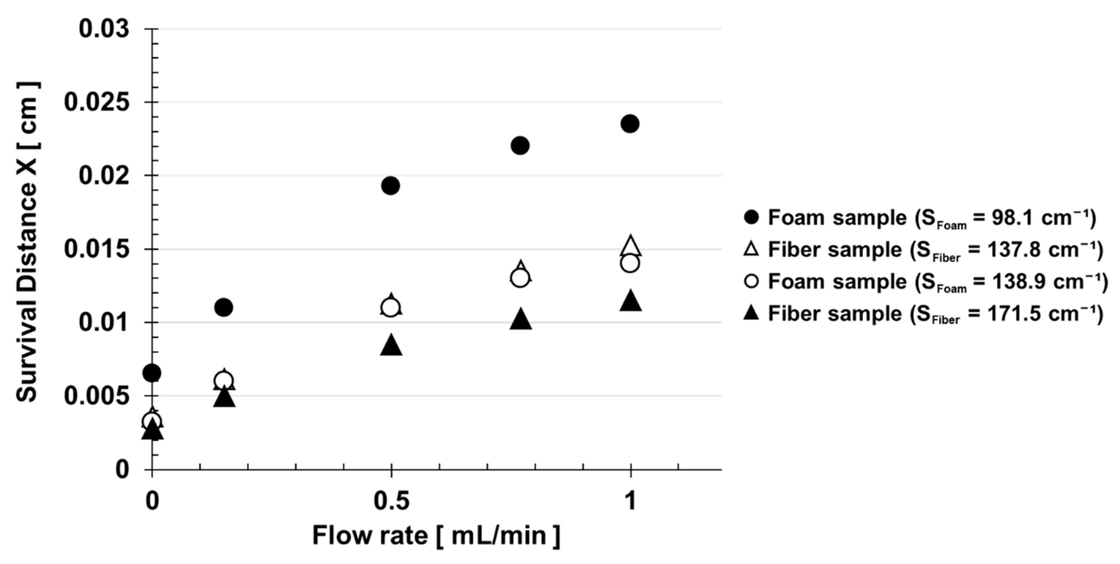
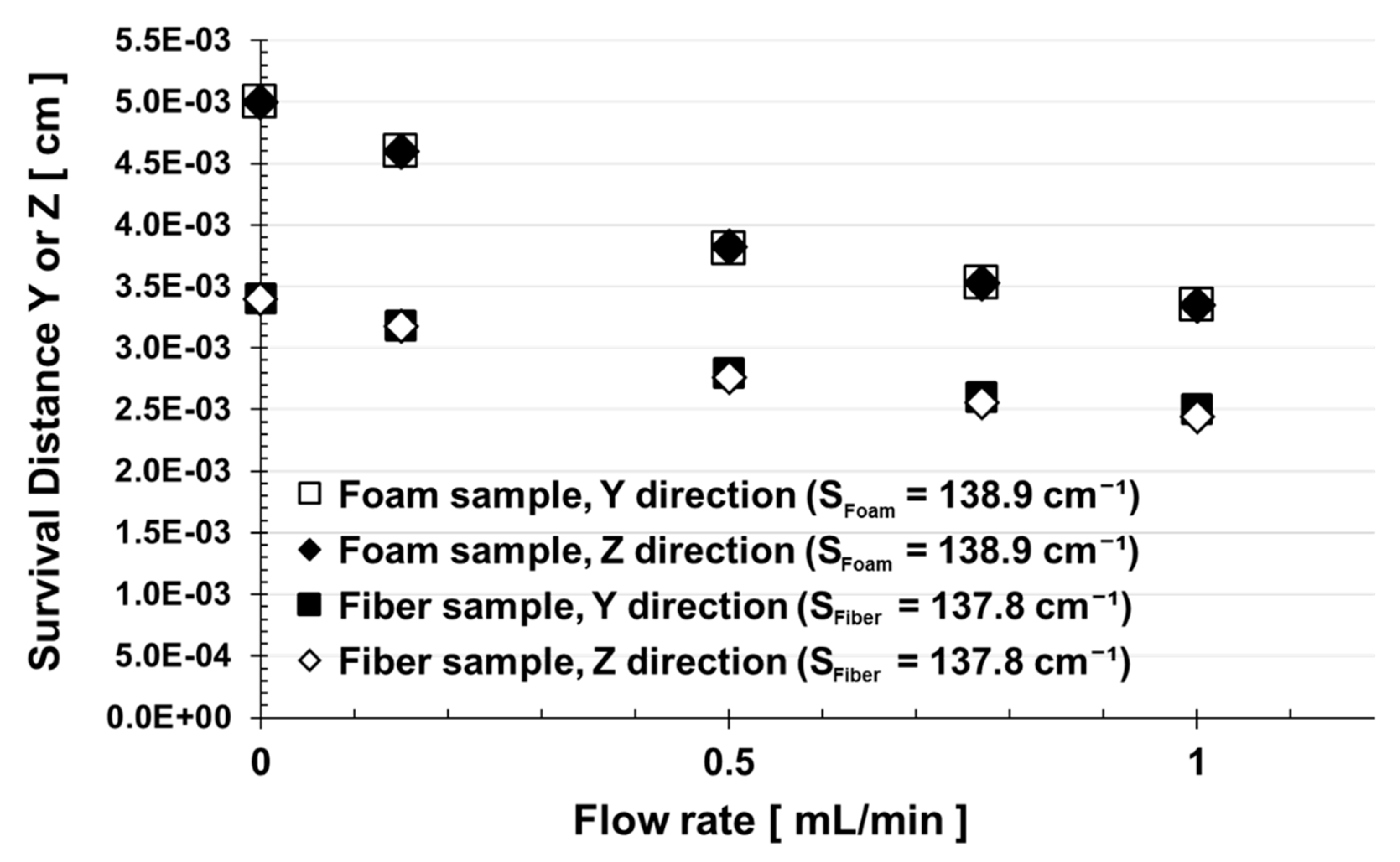
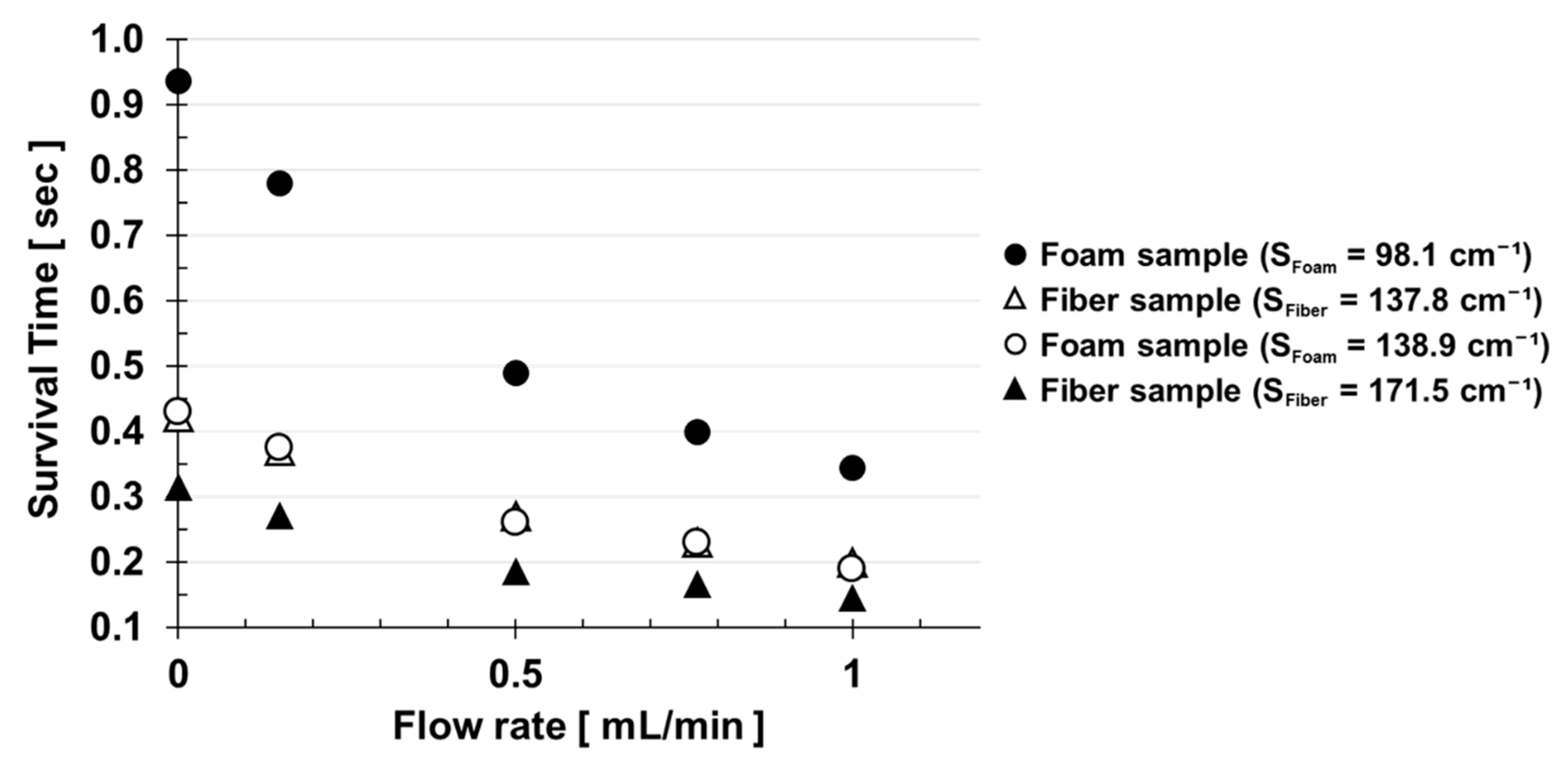
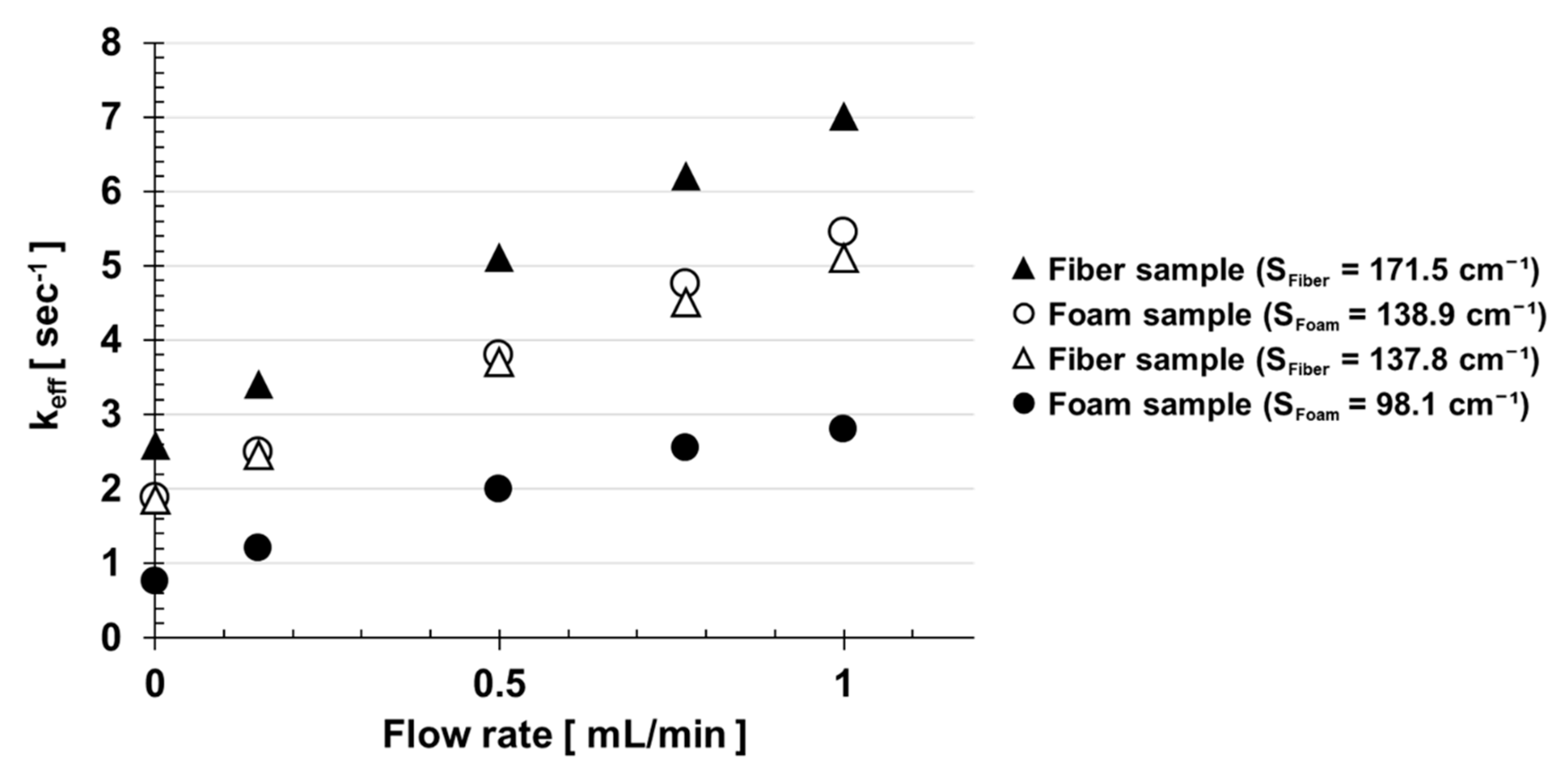
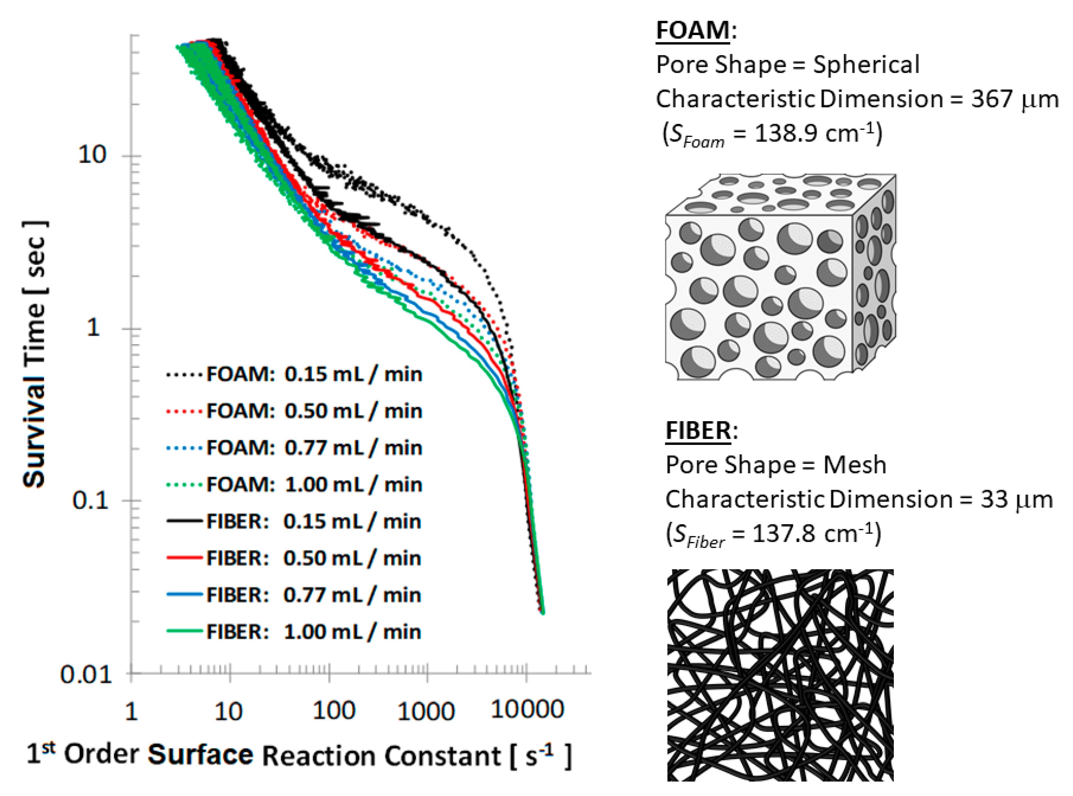
The full details of the rLST code can be found in our prior publications [20,26]. Briefly, the trajectories of the rLST particles are determined by contributions from convection (obtained using the velocity field from the LBM simulations) and diffusion (i.e., Brownian motion obtained from a mesoscopic Monte-Carlo approach). For example, the new X position of a marker at time t+1 is calculated from the previous position at time t as follows:
X t + 1 = X t + U t ( L B M ) Δ t + Δ X t ( r a n d o m )
where U t is the fluid velocity at the particle’s location at time t, as obtained from the LBM solver. On the other hand, the random jump has a standard deviation that is given by σ = 2 D 0 Δ t = 2 ν Δ t / S c , where D0 is the nominal molecular diffusivity (i.e., the diffusivity that the particles would have if their motion was purely Brownian). It can also be expressed in terms of the dimensionless Schmidt number Sc, which depends on the carrier fluid’s viscosity. The molecular diffusivity of O2 in the cell culture medium (assumed to be an aqueous solution at the physiological temperature of T = 37 °C) was 2.62 × 10⁻⁵ cm2/s, which corresponded to a Schmidt number of 328.14.
The rLST simulations were performed using 1 million particles, which was found to be sufficient to reproduce analytical results from the Taylor–Aris formula, during the validation runs. Their initial positions were distributed uniformly in a release plane at the pipe’s entrance. Furthermore, in order to model the O2 consumption by the cells, each of the rLST particles had a probability ‘q’ to react upon colliding with the scaffold walls: ranging from q = 0 (non-reactive) to q = 1 (fully reactive).
It was also assumed that the scaffold’s surface was uniformly covered with a monolayer of the cells, each of them capable of consuming the O2. Since second order reactions (reactions between solute particles) were not considered for this model, any interactions between the rLST markers were neglected (i.e., they did not affect each other’s path). This approximation is good for a dilute solution. The simulation was allowed to evolve for a total of 10,000-time steps, which were needed to achieve equilibration. The ’Mersenne Twister’ random number generator with a cycle of length (219937 −1) was used for all random number generation in the rLST code [35].

3. Results

As previously discussed, efficient delivery of O2 is vital to the cell survival in the 3D bone tissue engineering scaffolds. Yet, choosing the optimal scaffold manufacturing parameters and the culturing flow conditions is non-trivial, due to the complex transport phenomena occurring in the pore networks of the engineered tissue constructs. For this reason, we have performed image-based simulation of the fluid flow and of the O2 transport that occur within two common types of bone tissue engineering PLLA scaffolds: the salt-leached foam and the non-woven fiber mesh.
Their geometries were varied by controlling the amount and the size of the leached salt grains for the former, and the fiber diameter for the latter. In order to compare the scaffolds on the same scale, here the results are plotted as a function of the “specific surface area”—defined as the ratio of surface area to total volume (as opposed to just solid volume). Furthermore, in order to analyze how the transport of O2 is affected by the rate at which it is consumed by the cells, we considered different probabilities with which its molecules can react upon colliding with the scaffold walls. Specifically, we examined the condition of a uniform coverage of the scaffold surfaces with O2-starved cells in Figure 3, Figure 4, Figure 5 and Figure 6, while Figure 7 considers the case of the cells not starved for O2. Namely, the former corresponds to an infinite surface reaction rate (i.e., instantaneous consumption of every O2 molecule that collides with a scaffold wall). It should be treated as a limiting case scenario, which allows for a comparison of different scaffold structures on an equivalent basis.
Figure 3 is a plot of the O2 “survival distance” in the stream-wise direction (the X-direction), as a function of the scaffold structure and the cell-culture media perfusion flow rate. The survival distance is defined as the distance that the rLST markers (representing the O2 molecules) travel on average, until they are “consumed” via a collision with a scaffold wall. From this figure, it is apparent that the survival distance in the stream-wise direction increases as the flow rate goes up. This is consistent with the Taylor–Aris dispersion theory, which states that the effective diffusivity in the stream-wise direction should increase with the square of the Peclet number [20,34]:
P e m = R e S c
where Re is the Reynolds number and Sc is the Schmidt Number. Its physical meaning is the ratio of the transport by advection to transport by diffusion. In this study, Sc is fixed for an O2 molecule in an aqueous cell culture media at T = 37 °C, as was discussed in the methods section. Hence, according to Equation (2), the Peclet number will increase proportionally with the value of Re, which depends on the velocity of the fluid. This leads to a higher effective diffusivity of the solute in the stream-wise direction, and thus, the O2 can make it further into the scaffold before it is fully consumed by the cells.
Another trend that is apparent from Figure 3 is that the survival distance of O2 is also inversely proportional to the specific surface area of the scaffold. This makes sense, because the O2 molecules have a smaller chance to collide with the scaffold’s surface when it has less area exposed. Furthermore, Figure 3 shows that the foam scaffolds have a lower specific surface area than the fiber ones. This leads to noticeably longer survival distances of O2 in the foam scaffolds.
Overall, the result demonstrates that it is plausible to modify the scaffold’s geometry in order to increase the efficiency of the O2 transport within its structure. To that end, Equation (3) shows how the surface area-to-total volume ratio ‘S’ of a fiber mesh scaffold is related to its porosity and fiber diameter (see Supplementary Materials for derivation):
S F i b e r = 4 ( 1 ε ) D F i b e r
where DFiber is the fiber diameter and ε is the scaffold porosity. Similarly, Equation (4) shows how the surface area-to-total volume ratio ‘S’ of a foam scaffold is related to its porosity and salt grain diameter (see Supplementary Materials for derivation):
S F o a m = 6 ε D S a l t G r a i n
where DSaltGrain is the diameter of the salt grains used for leaching, and ε is the scaffold porosity. Therefore, for a known scaffold porosity and diameter combination, one can relate these geometric parameters to the surface area-to-total volume ratio of the scaffold (and thus, to the results of this manuscript). It is also important to note that while SFiber goes down with an increasing porosity ε, SFoam displays the opposite behavior, as can be seen from the Equations (3) and (4).
Interestingly, the survival distances in the Y and Z directions (i.e., perpendicular to the flow) go down with the increasing flow rate (see Figure 4). The reason behind this is likely due to the particles becoming entrained by the carrier fluid. Consequently, they move less in the Y and Z directions per time step, relative to their displacement in the X. As a result, there is a smaller probability of collisions with the walls in the former directions. However, since both the Y and Z survival distances are an order of magnitude smaller than those in the X direction, the total survival distance is dominated by the trend displayed by the latter.
Another quantity of interest is the survival time of the O2 molecules in the scaffolds. Figure 5 plots this quantity as a function of the flow rate and the specific surface area of the scaffolds for the limiting case of fully reactive rLST particles. Conversely to the survival distance in Figure 3, the survival time in Figure 5 decreases with the flow rate, though the effect of the specific surface area remains the same, and the survival time varies inversely-proportionally to it. Combining the results from both of the figures, it becomes apparent that fully reactive molecules get carried to a farther distance by a higher flow rate. However, they take a shorter time to get consumed by the cells on the surface of the scaffolds. This is especially true for the scaffold geometries with a higher exposed surface area.
Ultimately, it is of interest to measure the effective first order reaction rate constant keff, with which the O2 molecules get consumed in the scaffolds, after accounting for the mass transfer limitations. To that end, Figure 6 is a plot of keff as a function of the flow rate and specific surface area of the scaffold for the limiting case of an infinitely fast surface consumption of O2. It reaffirms the previously observed trends, which show that the O2 is consumed faster in the scaffold structures with the higher surface area-to-solid volume ratios. Furthermore, it also supports the finding that increasing the cell culture media flow rate through the scaffold leads to a faster O2 consumption in its pores.
If the cells are not starved for O2, however, the rLST particles can be made to have a finite (as opposed to infinite) probability of becoming consumed upon collision with the scaffold walls. Thus, Figure 7 explores the role that the different cell affinities for consuming the O2 have on its transport in the pores. In this case, the rLST particles with the different reactivities are all released simultaneously, and their survival times are compared as a function of the cell culture media flow rate and the scaffold type.
Two trends are immediately apparent from Figure 7: 1) the O2 in the fiber scaffolds (solid lines) has a shorter survival time than in the foam ones (dotted lines), regardless of the cells’ affinity for its uptake. This is consistent with the trends in the previous section, which showed that the fiber scaffolds have a higher specific surface area than the foams. This makes them more efficient at delivering the O2 molecules to the cells; and 2) the second trend essentially says that for a given surface reaction rate, the consumption of O2 will take longer at the slower flows. This is again consistent with a similar trend that was shown in Figure 5, where the survival time increased with the slower flow rate.

4. Discussion

In this manuscript, we carried out a study of how the O2 mass transfer is affected by the scaffold manufacturing and the flow perfusion culturing parameters in bone tissue engineering scaffolds. The knowledge obtained from the reported results is needed in order to overcome the product-size limitations, which are commonly experienced due to hypoxia and necrosis in the center of large scaffolds. To solve the problem, we used an image-based approach of scanning the true scaffold structures in 3D using a high resolution µCT, and then fed the obtained geometries to our in-house parallelized fluid flow (LBM) and mass transport (rLST) solvers. Two scaffolds commonly used in bone tissue engineering, the salt leached foam and the nonwoven fiber mesh, were used for this study. The O2 transport results were parametrized as a function of the specific surface area of the scaffold, the flow rate in the bioreactor, and the affinity to consume the molecule by the cells.
The main conclusions from our work are that the scaffolds with the higher specific area (i.e., surface area-to-solid volume ratio) result in more frequent molecular collisions with the cells. This increases the chances of the O2 uptake by them, which results in a higher consumption (i.e., shorter survival times and distances) of the molecules in the scaffold. Furthermore, by increasing the flow rate in the bioreactor, the O2 transport can be both facilitated (as seen from the shorter survival time in Figure 4) and delivered deeper into the scaffold (as seen from the longer survival distance in Figure 3). Thus, the overall effective O2 reaction coefficient keff can be increased by maximizing both the specific surface area of the scaffold and the flowrate through its pores. This is evident from Figure 6.
Interestingly, the conclusion that an increased flow rate improves the O2 delivery to the cells has also been reported by Bergemann et al. [4]. However, increasing it indefinitely is not an option because there is a trade-off with the shear forces exerted on the cells by the flow. Specifically, values in the range of 0.1–25 dynes/cm2 [36,37,38] are generally considered to be beneficial because they mimic the natural microenvironment in bone canaliculi [9,10] and have been shown to promote tissue regeneration [39,40,41,42]. On the other hand, an excessive shear in the range of 26–54 dynes/cm2 and higher can cause cell lysing and/or detachment from the scaffold [43,44]. Therefore, there is some optimal flow rate, which was found to be 45 μL/min by the Bergemann et al. study [4]. However, this value is specific to their scaffold-and-cell combination, and it could vary for other alternatives. Therefore, both image-based numerical simulations and cell viability assays are necessary for tuning the optimal conditions for other types of cultures. Whereas, at least the physical understanding provided in our study should be applicable across all scaffold types because they are expressed in terms of the specific surface area.
Finally, Figure 7 in our manuscript provides insight into how the O2 transport depends on its consumption by the cells. In this case, we are not assuming that the cells are O2-starved (and as a result take up every oxygen molecule that collides with them). Instead, we vary consumption rate of the O2 at the scaffold surface in order to measure how this affects its transport in the scaffold. The results reported in this figure allow other researchers to understand the changes in the scaffold’s transport microenvironment over time. They also show how the flowrate and specific surface area trends are affected by the cell-specific O2 consumption rates.
The limitations of our study are that the cells are assumed to have a uniformed coverage on the scaffold surface. In reality, they would likely prefer some areas of the scaffold more than others. Furthermore, the tissue they lay down and the forces they exert on the scaffold would likely alter the internal structure of the scaffold (and in turn the flow field in its pores). Unfortunately, our model does not account for these types of influences by the cells on the mass transfer of O2. Additionally, the scaffold’s structure in the real experiment could change due to wetting forces, fiber flexibility, and the natural degradation of PLLA. The latter produces acidic byproducts, whose removal is facilitated by the fluid flow [45], yet in our study, the scaffold’s structure remains static throughout the virtual experiment.
However, the results presented in this manuscript expose qualitative trends that should hold true regardless of the necessary simplifications. Therefore, it is expected that they should contribute significantly to the field of bone tissue engineering scaffold design and experiment optimization.

5. Conclusions

Mass transfer of O2 in scaffolds cultured in perfusion bioreactors is of interest to the fields of bone and other types of tissue engineering. Specifically, understanding how to control it can be instrumental to resolving product size limitations when it comes to culturing organ-sized scaffolds. Therefore, we performed an image-based simulation study, in which we showed that the scaffolds with the higher surface area-to-solid volume ratio result in a more efficient transfer of O2. Additionally, we showed that the effect can be increased further by flowing the cell culture media through the scaffold faster. Serendipitously, this also delivers the O2 deeper into the scaffold pores, which is key to overcoming the product-size limitations mentioned earlier. Furthermore, we provided a parametric sweep over the rates of O2 consumption by the cells situated on the scaffold surfaces. This visual aid yields insight into how the different cell affinities for consuming the O2 can affect the molecule’s transport through the biological porous media. Finally, the computational framework presented in this study can serve as a viable tool for optimizing the scaffold design and experimental culturing protocols for other types of tissue engineering as well.

Supplementary Materials

The following are available online at https://www.mdpi.com/2076-3417/9/11/2381/s1.

Author Contributions

Conceptualization, S.V.I. and V.R.S.; methodology, N.T.D., K.O.E.; software, V.R.S.; validation, N.T.D., and K.O.E.; formal analysis, N.T.D., and K.O.E.; investigation, N.T.D., and K.O.E.; resources, S.V.I.; data curation, N.T.D.; writing—original draft preparation, N.T.D. and K.O.E.; writing—review and editing, N.T.D., K.O.E., S.V.I. and V.R.S.; visualization, N.T.D. and K.O.E.; supervision, V.R.S.; project administration V.R.S.; funding acquisition, V.R.S.

Funding

This research was funded by Gustavus and Louise Pfeiffer Research Foundation Major Research Investment Grant.

Acknowledgments

Financial support from Gustavus and Louise Pfeiffer Research Foundation is gratefully acknowledged. We also acknowledge the computing for this project was performed at the OU Supercomputing Center for Education & Research (OSCER) at the University of Oklahoma (OU) and Texas Advanced Computing Center (TACC) at The University of Texas–Austin. Both have contributed to the research results reported within this paper. URLs: http://www.ou.edu/oscer.html and http://www.tacc.utexas.edu, respectively. This work also used the Extreme Science and Engineering Discovery Environment (XSEDE) [46], which is supported by National Science Foundation grant number ACI-1548562. Allocations: TG-BCS170001 and TG-BIO160074. The Xradia micro-CT scans were made by Mark E. Curtis. Fiber fabrication was performed by Taren Blue, who was studying under the guidance of Prof. Robert L. Shambaugh at OU. Scaffolds were cultured by Sam VanGordon and Cortes Williams also at OU. Finally, the LBM and rLST codes were written under the guidance of Prof. Papavassiliou also at OU. We gratefully acknowledge their expertise and assistance.

Conflicts of Interest

The authors have no competing financial interests to declare.

References

  1. American Academy of Orthopaedic Surgeons. One in Two Americans Have a Musculoskeletal Condition. Available online: https://www.sciencedaily.com/releases/2016/03/160301114116.htm (accessed on 13 June 2018).
  2. U.S. Food and Drug Administration. Approved Cellular and Gene Therapy Products. Available online: https://www.fda.gov/vaccines-blood-biologics/cellular-gene-therapy-products/approved-cellular-and-gene-therapy-products (accessed on 20 February 2018).
  3. Simmons, A.D.; Williams, C.; Degoix, A.; Sikavitsas, V.I. Sensing metabolites for the monitoring of tissue engineered construct cellularity in perfusion bioreactors. Biosens. Bioelectron. 2017, 90, 443–449. [Google Scholar] [CrossRef] [PubMed]
  4. Bergemann, C.; Elter, P.; Lange, R.; Weissmann, V.; Hansmann, H.; Klinkenberg, E.D.; Nebe, B. Cellular Nutrition in Complex Three-Dimensional Scaffolds: A Comparison between Experiments and Computer Simulations. Int. J. Biomater. 2015, 2015, 584362. [Google Scholar] [CrossRef] [PubMed]
  5. Gilkes, D.M.; Semenza, G.L.; Wirtz, D. Hypoxia and the extracellular matrix: Drivers of tumour metastasis. Nat. Rev. Cancer 2014, 14, 430. [Google Scholar] [CrossRef]
  6. Spill, F.; Reynolds, D.S.; Kamm, R.D.; Zaman, M.H. Impact of the physical microenvironment on tumor progression and metastasis. Curr. Opin. Biotechnol. 2016, 40, 41–48. [Google Scholar] [CrossRef] [PubMed] [Green Version]
  7. Nguyen, T.D.; Song, M.S.; Ly, N.H.; Lee, S.Y.; Joo, S.W. Nanostars on Nanopipette Tips: A Raman Probe for Quantifying Oxygen Levels in Hypoxic Single Cells and Tumours. Angew. Chem. Int. Ed. Engl. 2019, 58, 2710–2714. [Google Scholar] [CrossRef]
  8. Zhang, S.; Vijayavenkataraman, S.; Lu, W.F.; Fuh, J.Y. A review on the use of computational methods to characterize, design, and optimize tissue engineering scaffolds, with a potential in 3D printing fabrication. J. Biomed. Mater. Res. Part B Appl. Biomater. 2018, 107, 1329–1351. [Google Scholar] [CrossRef]
  9. Verbruggen, S.W.; Vaughan, T.J.; McNamara, L.M. Fluid flow in the osteocyte mechanical environment: A fluid-structure interaction approach. Biomech. Model Mechanobiol. 2014, 13, 85–97. [Google Scholar] [CrossRef]
  10. Guyot, Y.; Luyten, F.P.; Schrooten, J.; Papantoniou, I.; Geris, L. A three-dimensional computational fluid dynamics model of shear stress distribution during neotissue growth in a perfusion bioreactor. Biotechnol. Bioeng. 2015, 112, 2591–2600. [Google Scholar] [CrossRef] [Green Version]
  11. Ferroni, M.; Giusti, S.; Nascimento, D.; Silva, A.; Boschetti, F.; Ahluwalia, A. Modeling the fluid-dynamics and oxygen consumption in a porous scaffold stimulated by cyclic squeeze pressure. Med. Eng. Phys. 2016, 38, 725–732. [Google Scholar] [CrossRef]
  12. Fiedler, T.; Belova, I.V.; Murch, G.E.; Poologasundarampillai, G.; Jones, J.R.; Roether, J.A.; Boccaccini, A.R. A comparative study of oxygen diffusion in tissue engineering scaffolds. J. Mater. Sci. Mater. Med. 2014, 25, 2573–2578. [Google Scholar] [CrossRef]
  13. Arrigoni, C.; Bongio, M.; Talò, G.; Bersini, S.; Enomoto, J.; Fukuda, J.; Moretti, M. Rational design of prevascularized large 3D tissue constructs using computational simulations and biofabrication of geometrically controlled microvessels. Adv. Healthcare Mater. 2016, 5, 1617–1626. [Google Scholar] [CrossRef] [PubMed]
  14. Li, E.; Chang, C.; Zhang, Z.; Li, Q. Characterization of tissue scaffolds for time-dependent biotransport criteria–a novel computational procedure. Comput. Methods Biomech. Biomed. Eng. 2016, 19, 1210–1224. [Google Scholar] [CrossRef] [PubMed]
  15. Yan, X.; Bergstrom, D.J.; Chen, X.B. Modeling of cell cultures in perfusion bioreactors. IEEE Trans. Biomed. Eng. 2012, 59, 2568–2575. [Google Scholar] [CrossRef]
  16. Voronov, R.; Vangordon, S.; Sikavitsas, V.I.; Papavassiliou, D.V. Computational modeling of flow-induced shear stresses within 3D salt-leached porous scaffolds imaged via micro-CT. J. Biomech. 2010, 43, 1279–1286. [Google Scholar] [CrossRef] [PubMed]
  17. VanGordon, S.B.; Voronov, R.S.; Blue, T.B.; Shambaugh, R.L.; Papavassiliou, D.V.; Sikavitsas, V.I. Effects of Scaffold Architecture on Preosteoblastic Cultures under Continuous Fluid Shear. Ind. Eng. Chem. Res. 2011, 50, 620–629. [Google Scholar] [CrossRef]
  18. Papavassiliou, D.V.; Pham, N.H.; Kadri, O.E.; Voronov, R.S. Chapter 23—Lattice Boltzmann Methods for Bioengineering Applications. In Numerical Methods and Advanced Simulation in Biomechanics and Biological Processes; Academic Press: Cambridge, MA, USA, 2018; pp. 415–429. [Google Scholar]
  19. Alam, T.A.; Pham, Q.L.; Sikavitsas, V.I.; Papavassiliou, D.V.; Shambaugh, R.L.; Voronov, R.S. Image-based modeling: A novel tool for realistic simulations of artificial bone cultures. Technology 2016, 4, 229–233. [Google Scholar] [CrossRef]
  20. Voronov, R.S.; VanGordon, S.B.; Sikavitsas, V.I.; Papavassiliou, D.V. Efficient Lagrangian scalar tracking method for reactive local mass transport simulation through porous media. Int. J. Numer. Methods Fluids 2011, 67, 501–517. [Google Scholar] [CrossRef]
  21. Lu, L.C.; Peter, S.J.; Lyman, M.D.; Lai, H.L.; Leite, S.M.; Tamada, J.A.; Vacanti, J.P.; Langer, R.; Mikos, A.G. In vitro degradation of porous poly(L-lactic acid) foams. Biomaterials 2000, 21, 1595–1605. [Google Scholar] [CrossRef]
  22. Alvarez-Barreto, J.F.; Sikavitsas, V.I. Improved mesenchymal stem cell seeding on RGD-modified poly(L-lactic acid) scaffolds using flow perfusion. Macromol Biosci 2007, 7, 579–588. [Google Scholar] [CrossRef]
  23. Mikos, A.G.; Lyman, M.D.; Freed, L.E.; Langer, R. Wetting of poly(L-lactic acid) and poly(DL-lactic-co-glycolic acid) foams for tissue culture. Biomaterials 1994, 15, 55–58. [Google Scholar] [CrossRef]
  24. Liu, X.; Ma, P.X. Polymeric scaffolds for bone tissue engineering. Ann. Biomed. Eng. 2004, 32, 477–486. [Google Scholar] [CrossRef] [PubMed]
  25. Voronov, R.S.; VanGordon, S.B.; Shambaugh, R.L.; Papavassiliou, D.V.; Sikavitsas, V.I. 3D Tissue-Engineered Construct Analysis via Conventional High-Resolution Microcomputed Tomography Without X-Ray Contrast. Tissue Eng. Part C-Methods 2013, 19, 327–335. [Google Scholar] [CrossRef] [PubMed]
  26. Voronov, R. Fluid Shear Stress and Nutrient Transport effects via Lattice-Boltzmann and Lagrangian Scalar Tracking Simulations of Cell Culture Media Perfusion through Artificial Bone Engineering Constructs Imaged with microCT. Ph.D. Thesis, University of Oklahoma, Norman, OK, USA, 2010. [Google Scholar]
  27. Porter, B.; Zauel, R.; Stockman, H.; Guldberg, R.; Fyhrie, D. 3-D computational modeling of media flow through scaffolds in a perfusion bioreactor. J. Biomech. 2005, 38, 543–549. [Google Scholar] [CrossRef] [PubMed]
  28. Shakhawath Hossain, M.; Bergstrom, D.J.; Chen, X.B. A mathematical model and computational framework for three-dimensional chondrocyte cell growth in a porous tissue scaffold placed inside a bi-directional flow perfusion bioreactor. Biotechnol. Bioeng. 2015, 112, 2601–2610. [Google Scholar] [CrossRef] [PubMed]
  29. Williams, C.; Kadri, O.; Voronov, R.; Sikavitsas, V. Time-Dependent Shear Stress Distributions during Extended Flow Perfusion Culture of Bone Tissue Engineered Constructs. Fluids 2018, 3, 25. [Google Scholar] [CrossRef]
  30. Wang, J.; Zhang, X.; Bengough, A.G.; Crawford, J.W. Domain-decomposition method for parallel lattice Boltzmann simulation of incompressible flow in porous media. Phys. Rev. E 2005, 72, 016706. [Google Scholar] [CrossRef] [PubMed]
  31. Kadri, O.E.; Williams, C., 3rd; Sikavitsas, V.; Voronov, R.S. Numerical accuracy comparison of two boundary conditions commonly used to approximate shear stress distributions in tissue engineering scaffolds cultured under flow perfusion. Int. J. Numer. Method Biomed. Eng. 2018, 34, e3132. [Google Scholar] [CrossRef] [PubMed]
  32. Qian, Y.H.; Dhumieres, D.; Lallemand, P. Lattice Bgk Models for Navier-Stokes Equation. Europhys. Lett. 1992, 17, 479–484. [Google Scholar] [CrossRef]
  33. Bhatnagar, P.L.; Gross, E.P.; Krook, M. A Model for Collision Processes in Gases.1. Small Amplitude Processes in Charged and Neutral One-Component Systems. Phys. Rev. 1954, 94, 511–525. [Google Scholar] [CrossRef]
  34. Sukop, M.C.; Thorne, D.T.; NetLibrary Inc. Lattice Boltzmann Modeling an Introduction for Geoscientists and Engineers; Springer: Berlin, Germany; New York, NY, USA, 2006. [Google Scholar]
  35. Matsumoto, M.; Nishimura, T. Mersenne twister: A 623-dimensionally equidistributed uniform pseudo-random number generator. ACM Trans. Model. Comput. Simul. 1998, 8, 3–30. [Google Scholar] [CrossRef]
  36. Stolberg, S.; McCloskey, K.E. Can shear stress direct stem cell fate? Biotechnol. Progr. 2009, 25, 10–19. [Google Scholar] [CrossRef] [PubMed]
  37. Raimondi, M.T.; Moretti, M.; Cioffi, M.; Giordano, C.; Boschetti, F.; Lagana, K.; Pietrabissa, R. The effect of hydrodynamic shear on 3D engineered chondrocyte systems subject to direct perfusion. Biorheology 2006, 43, 215–222. [Google Scholar] [PubMed]
  38. Kim, K.M.; Choi, Y.J.; Hwang, J.-H.; Kim, A.R.; Cho, H.J.; Hwang, E.S.; Park, J.Y.; Lee, S.-H.; Hong, J.-H. Shear Stress Induced by an Interstitial Level of Slow Flow Increases the Osteogenic Differentiation of Mesenchymal Stem Cells through TAZ Activation. PLoS ONE 2014, 9, e92427. [Google Scholar] [CrossRef] [PubMed]
  39. Miyashita, S.; Ahmed, N.E.M.B.; Murakami, M.; Iohara, K.; Yamamoto, T.; Horibe, H.; Kurita, K.; Takano-Yamamoto, T.; Nakashima, M. Mechanical forces induce odontoblastic differentiation of mesenchymal stem cells on three-dimensional biomimetic scaffolds. J. Tissue Eng. Regener. Med. 2017, 11, 434–446. [Google Scholar] [CrossRef] [PubMed]
  40. Zhao, F.; Vaughan, T.J.; McNamara, L.M. Quantification of fluid shear stress in bone tissue engineering scaffolds with spherical and cubical pore architectures. Biomech. Model. Mechanobiol. 2016, 15, 561–577. [Google Scholar] [CrossRef] [PubMed]
  41. Sikavitsas, V.I.; Bancroft, G.N.; Holtorf, H.L.; Jansen, J.A.; Mikos, A.G. Mineralized matrix deposition by marrow stromal osteoblasts in 3D perfusion culture increases with increasing fluid shear forces. Proc. Natl. Acad. Sci. USA 2003, 100, 14683–14688. [Google Scholar] [CrossRef] [PubMed] [Green Version]
  42. Yourek, G.; McCormick, S.M.; Mao, J.J.; Reilly, G.C. Shear stress induces osteogenic differentiation of human mesenchymal stem cells. Regener. Med. 2010, 5, 713–724. [Google Scholar] [CrossRef] [Green Version]
  43. Brindley, D.; Moorthy, K.; Lee, J.-H.; Mason, C.; Kim, H.-W.; Wall, I. Bioprocess Forces and Their Impact on Cell Behavior: Implications for Bone Regeneration Therapy. J. Tissue Eng. 2011, 2011, 620247. [Google Scholar] [CrossRef]
  44. Alvarez-Barreto, J.F.; Linehan, S.M.; Shambaugh, R.L.; Sikavitsas, V.I. Flow Perfusion Improves Seeding of Tissue Engineering Scaffolds with Different Architectures. Ann. Biomed. Eng. 2007, 35, 429–442. [Google Scholar] [CrossRef]
  45. Agrawal, C.M.; McKinney, J.S.; Lanctot, D.; Athanasiou, K.A. Effects of fluid flow on the in vitro degradation kinetics of biodegradable scaffolds for tissue engineering. Biomaterials 2000, 21, 2443–2452. [Google Scholar] [CrossRef]
  46. Towns, J.; Cockerill, T.; Dahan, M.; Foster, I.; Gaither, K.; Grimshaw, A.; Hazlewood, V.; Lathrop, S.; Lifka, D.; Peterson, G.D.; et al. XSEDE: Accelerating Scientific Discovery. Comput. Sci. Eng. 2014, 16, 62–74. [Google Scholar] [CrossRef]
Figure 1. The image-based modeling methodology used in this work; scaffolds are scanned in 3D via high resolution μCT, reconstructed in silico, and the resulting geometries are used by the LBM and rLST solvers.
Applsci 09 02381 g001
Figure 2. Visual comparison of the two scaffold architecture types used in this study. LEFT COLUMN—Salt-Leached Porous Foam Scaffold; RIGHT COLUMN—Non-woven Fiber Mesh Scaffold. TOP ROW—Three dimensional reconstructions of 8-mm-diameter and 2.3-mm-thickness scaffolds, obtained via µCT imaging (described in our previous works [16,17,25]). BOTTOM ROW—SEM close-ups of representative regions on the scaffolds’ surfaces. Images are shown at two different magnifications to illustrate morphological feature scales of the two scaffold types. Both of the scaffolds are made from poly-L-lactic acid.
Applsci 09 02381 g002
Figure 3. Survival distance in the stream-wise direction as a function of perfusion flow rate and scaffold architecture. Data is plotted for the limiting case of the fully reactive Lagrangian Scalar Tracking (rLST) particles.
Applsci 09 02381 g003
Figure 4. Survival distances in the Y & Z directions, as a function of the scaffold geometry and perfusion flow rate. Data is plotted for the limiting case of the fully reactive rLST particles. Both scaffolds types are chosen to have a similar specific surface area.
Applsci 09 02381 g004
Figure 5. Survival time in the stream-wise direction as a function of perfusion flow rate and scaffold architecture. Data is plotted for the limiting case of the fully reactive rLST particles.
Applsci 09 02381 g005
Figure 6. Effective O2 reaction coefficient keff as a function of perfusion flow rate and scaffold architecture. Data is plotted for the limiting case of the fully reactive rLST particles.
Applsci 09 02381 g006
Figure 7. O2 survival time as a function of the consumption rate by the cells on the scaffold surface. Data is plotted for salt leached foam and non-woven fiber mesh scaffolds at four different flow rates.
Applsci 09 02381 g007
Table 1. Literature overview of O2 simulations in tissue engineering scaffolds, shows that image-based simulation of convection with diffusion and reaction has not yet been done.
Scaffold TypeSimulated
Geometry
O2 DiffusionO2 ConvectionO2 ReactionVaried ParameterCitation
45S5 Bioglass-PCL Robocast, Bioactive Glass 70S30C Sol-Gel Foamed and Titania Foam ReplicatedMicro-computed TomographyYesNoNoVoid FractionFiedler et al. [12]
Cardiac Tissue Eng.IdealizedYesYesNoSqueeze PressureFerroni et al. [11]
Microchanneled HydrogelIdealizedYesNoNoMicrochannel ConfigurationArrigoni et al. [13]
Periodically Self-Repeated Representative Volume ElementIdealizedYesNoYesGeometry of the Repeating ElementLi et al. [14]
Bone Tissue Eng. Molded TantalumIdealizedYesYesYesFlow rateBergemann et al. [4]
Homogeneous Porous MediumIdealizedYesYesYesFlow rate, PorosityYan et al. [15]

