2.1. Quasi-Solid Polymer Electrolyte Membranes by UV-induced Photo-Polymerization
The preparation of the quasi-solid polymer electrolyte membrane (namely, RC-1) involved the use of a reactive mixture prepared by mixing the materials described in paragraph 3.1 in definite proportions as described in
Table 1.
Table 1.
Exact compositions (in wt.%) of the reactive mixture used to prepare sample RC-1, along with its thermal properties.
Table 1.
Exact compositions (in wt.%) of the reactive mixture used to prepare sample RC-1, along with its thermal properties.
| sample | BEMA | PEGMA-475 | 1.5 M LiTFSI solution | Darocur1173 | Tg/°C | TGA/°C |
|---|
| T10 | T50 |
|---|
| RC-1 | 36 | 16 | 45 | 3 | −63.8 | 181 | 368 |
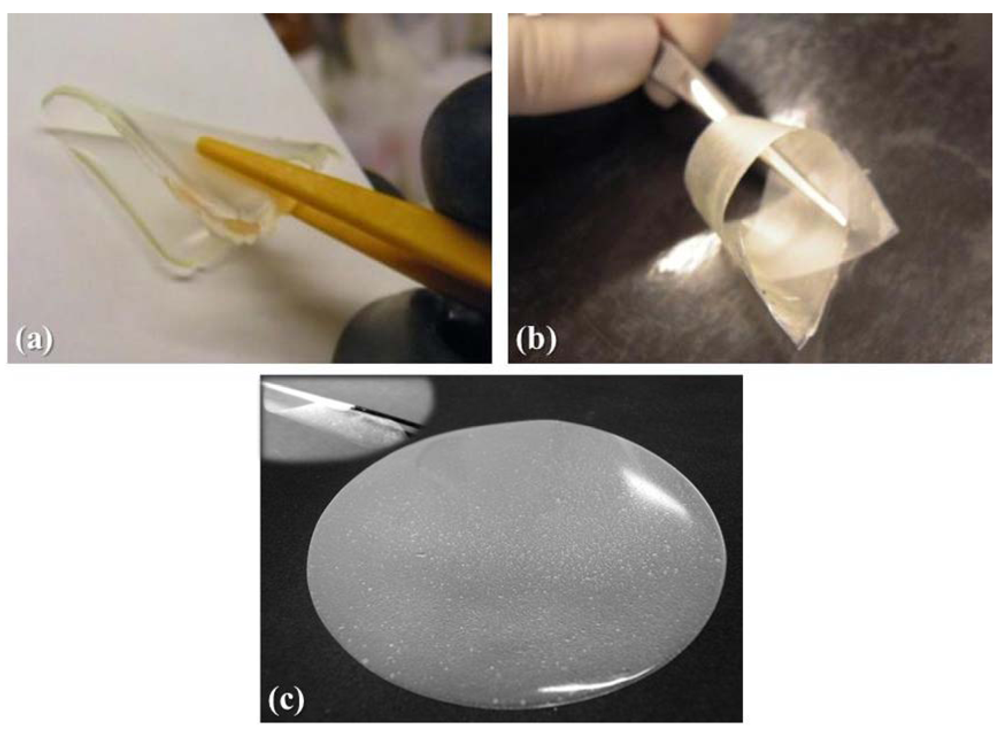
The polymer electrolyte membrane RC-1, obtained by copolymerizing the monomers BEMA and PEGMA-475 with the
in-situ addition of the lithium salt and the electrolyte solution on exposure to UV irradiation, is a transparent, freestanding, extremely flexible and non-sticky membrane, as shown in
Figure 1a.
The percentage of double bonds (>C=C<) conversion during UV exposure was evaluated from kinetic studies using real-time FT-IR technique. Results obtained showed that the reactivity of the monomers mixtures was in an acceptable range and a quantitative yield was obtained within a few seconds. In fact, the total conversion of reactive ingredients of RC-1 into products was around 63% and the respective maximum conversion was reached in less than 120 sec. A prolonged UV exposure time did not modify the total conversion. As already demonstrated [
19], a 180 sec time of irradiation was sufficient to achieve the maximum conversion.
The polymer membrane RC-1 showed a
Tg of −63.8 °C. Though the
Tg value was found to be very low, the obtained PE was still self-standing, extremely flexible and easy to handle. The thermal stability was assessed by thermo-gravimetric analysis under flowing nitrogen in a temperature range of between 25 and 600 °C. The results obtained demonstrated that the thermal stability of a pristine polymer membrane (
i.e., not containing the liquid electrolyte solution) was high, up to 300 °C [
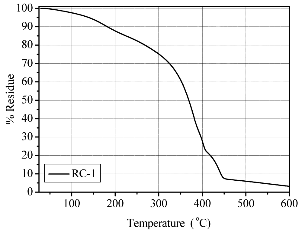
20]. The EC-DEC components of the liquid electrolyte restricted the thermal stability up to approximate 120 °C, when the solvents began to evaporate (in fact, a weight loss of approximate 5% occurred at about 150 °C). However, these results indicate that the obtained PE can be safely used up to 100 °C, still well within the limit for application as electrolyte in Li-based batteries. The TGA thermo-gram of the RC-1 polymer membrane is given in
Figure 2. It shows a T
10 value (
i.e., the temperature at which 10 wt.% of the sample is decomposed) of 181 °C and T
50 value (
i.e., the temperature at which 50 wt.% of the sample is decomposed) of 368 °C.
Figure 1.
Appearance of the different quasi-solid polymer electrolyte membranes prepared: (a) RC-1 obtained by copolymerizing the monomers BEMA and PEGMA-475 via UV irradiation with the in-situ addition of a 1.5 M LiTFSI electrolyte solution; (b) modified-cellulose handsheet reinforced MC-PE polymer electrolyte membrane; and (c) microfibrillated cellulose reinforced MFC-PE polymer electrolyte membrane.
Figure 2.
TGA analysis under N2 flux (temperature range 25–600 °C) for the RC-1 polymer electrolyte membrane.
Figure 2.
TGA analysis under N2 flux (temperature range 25–600 °C) for the RC-1 polymer electrolyte membrane.
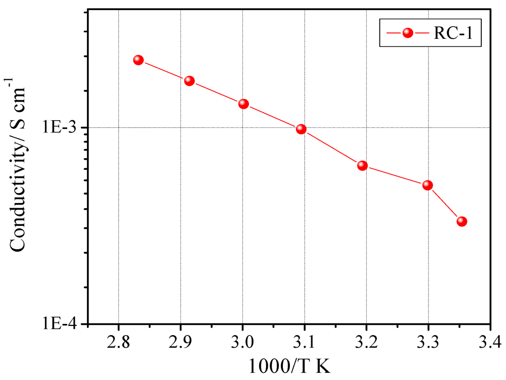
The ionic conductivity of the sample was tested by constructing a symmetric cell with the SS-316/RC-1/SS-316 configuration. The Arrhenius plot for sample RC-1 is reported in
Figure 3. The plot exhibited the typical Vogel-Tamman-Fulcher (VTF) curvature associated with amorphous materials [
20]. The optimum ionic conductivity values were achieved by varying the components concentration and their quantity. The rapid UV-induced photo-polymerization process gives this freedom to polymer chemists/electrochemists to fine tune each and every ingredient of the final reactive mixture along with a facile synthesizing procedure. The EIS studies clearly demonstrated that high ionic conductivity values were achieved, at ambient temperature as well as at 80 °C. In fact, RC-1 showed an ambient temperature conductivity of 3.3 × 10
−4 S cm
–1 and 2.2 × 10
−3 S cm
−1 at 80 °C.
Figure 3.
Ionic conductivity vs. temperature plot of sample RC-1. Data obtained by impedance spectroscopy.
Figure 3.
Ionic conductivity vs. temperature plot of sample RC-1. Data obtained by impedance spectroscopy.
In view of its possible application as electrolyte in lithium polymer batteries, the RC-1 polymer electrolyte membrane was further tested in terms of other general electrochemical properties, such as anodic stability window and interfacial stability vs. the lithium metal electrode. The electrochemical stability at potential values anodic with respect to lithium at a scan rate of 0.100 mV sec−1 was evaluated at ambient temperature. The current-voltage curve was obtained for a working acetylene black electrode swept in a cell using RC-1 as separator and a Li metal counter electrode. The onset of the current increase, which is representative of the decomposition of the electrolyte, indicates an anodic break-down voltage of approximate 4.5 V vs. Li. A high decomposition potential like the one showed by RC-1 membrane is certainly welcome from a practical application viewpoint. Moreover, the anodic scan showed very low residual current observed prior to breakdown voltage, confirming the purity of the prepared PE.
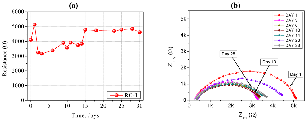
The impedance spectra carried out on a Li/RC-1/Li symmetrical cell stored for long time periods under open circuit potential conditions at ambient temperature are shown in
Figure 4a, b. It is well known that the resistance of the cell is composed of the bulk resistance (R
b) of the electrolyte and the interfacial resistance (R
i) which reflects the interfacial situation between the electrodes and the electrolyte. At high frequency, the intercept with the real part (Z
re) corresponds to the bulk resistance, and this allows calculation of the ionic conductivity of the PE. This value increased only slightly with time, meaning that the liquid electrolyte embedded into the polymer network did not lose its electrochemical properties because of the non-volatile nature of the organic solvents and it showed good compatibility with the lithium metal electrode. The value of R
i increased quickly during the first days, indicating the formation of the passivation layer onto the surface of the Li metal electrode as a result of the reactivity with the polymer electrolyte membrane. It subsequently decayed and, finally almost stabilized at a value ~4,700 Ω cm
−2. R
i remained very stable for a long period of time.
Figure 4.
(a) Time evolution of the interfacial stability of a Li/RC-1/Li symmetrical cell, stored under open circuit potential conditions at ambient temperature; (b) Impedance spectra (Nyquist plots) of the same Li/RC-1/Li symmetrical cell. Electrode area: 0.785 cm2. Frequency range: 1 Hz–100 KHz.
Figure 4.
(a) Time evolution of the interfacial stability of a Li/RC-1/Li symmetrical cell, stored under open circuit potential conditions at ambient temperature; (b) Impedance spectra (Nyquist plots) of the same Li/RC-1/Li symmetrical cell. Electrode area: 0.785 cm2. Frequency range: 1 Hz–100 KHz.
Finally, the RC-1 polymer electrolyte membrane was assembled in a complete lithium polymer cell laboratory prototype, and its electrochemical behavior was investigated by means of galvanostatic charge/discharge cycling. The response of the prototype, assembled by combining a lithium metal anode with a LiFePO
4/C composite cathode and the RC-1 PE as the electrolyte separator, is reported in
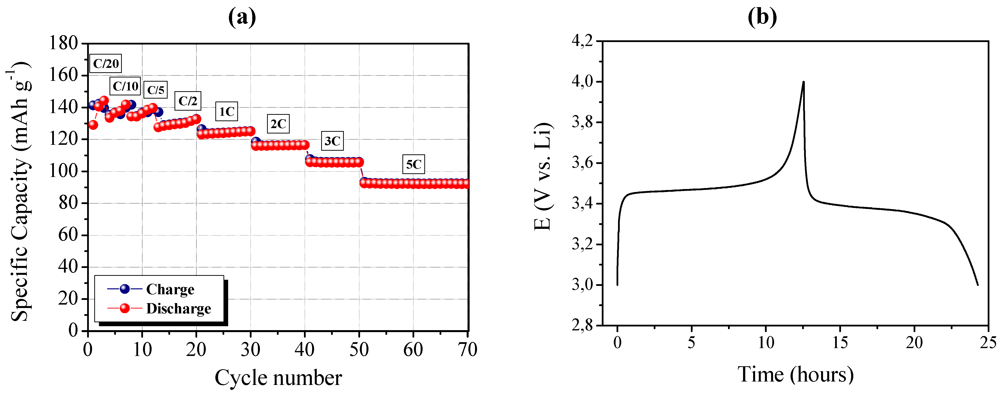
Figure 5. It shows the specific capacity of the cell as a function of the cycle number at ambient temperature and at different C-rates ranging from C/20 to 5C.
The cell delivered a specific discharge capacity higher than 140 mAh g
−1 during the initial cycles, when using the low current density of C/20. As the current density increased, the specific discharge capacity decreased only slightly. Actually, at the discharge rate of 1C, the cell was able to deliver a discharge capacity of about 125 mAh g
−1, and about 95 mAh g
−1 at the very high discharge rate of 5C. Good performance at high current rate might be ascribed to the efficient ionic conduction in the polymer separator and the favorable interfacial charge transport between electrodes and electrolyte in the cell.
Figure 5b shows a typical charge (lithium removal from LiFePO
4 to form FePO
4) and discharge (lithium acceptance by FePO
4 to reconvert into LiFePO
4) cycle run at ambient temperature. The potential drop in passing from charge to discharge was observed to be small, which means low diffusion resistance of the cell. The galvanostatic charge-discharge profiles showed very flat voltage plateaus at about 3.47 V
vs. Li on charge and at 3.38 V
vs. Li on discharge, reflecting the good properties of the LiFePO
4/C cathode, namely high specific capacity and steepness of the plateau with minimum over-potential.
Figure 5.
(a) Ambient temperature cycling performance of a LiFePO4/RC-1/Li polymer cell at different C-rates from C/20 to 5C (1C = 0.7 mA with respect to a LiFePO4 active mass of about 4 mg); (b) Typical charge and discharge cycle run at ambient temperature.
Figure 5.
(a) Ambient temperature cycling performance of a LiFePO4/RC-1/Li polymer cell at different C-rates from C/20 to 5C (1C = 0.7 mA with respect to a LiFePO4 active mass of about 4 mg); (b) Typical charge and discharge cycle run at ambient temperature.
2.2. Cellulose Handsheets Reinforced Quasi-Solid Polymer Electrolyte Membranes
In the previous paragraph, we described the characteristics and performance of a quasi-solid polymer electrolyte membrane obtained by a fast UV induced free radical photo-polymerization process. Although it showed remarkable electrochemical performances, its mechanical resistance was not fully satisfying under intense mechanical abuse. Thus, we tried to improve it, especially considering the possible application as separator in thin-film flexible cells. To this purpose, incorporation of modified cellulose (MC) handsheets as a reinforcement is here proposed to improve the mechanical behavior of quasi-solid polymer electrolytes. The composition of the polymeric matrix was the same as for the previously discussed RC-1 sample and the preparation method is discussed in Paragraph 3.3. The appearance of the reinforced gel-polymer electrolyte, namely MC-PE, is shown in
Figure 1b: it was a highly translucent, freestanding, extremely flexible and non-sticky membrane.
The
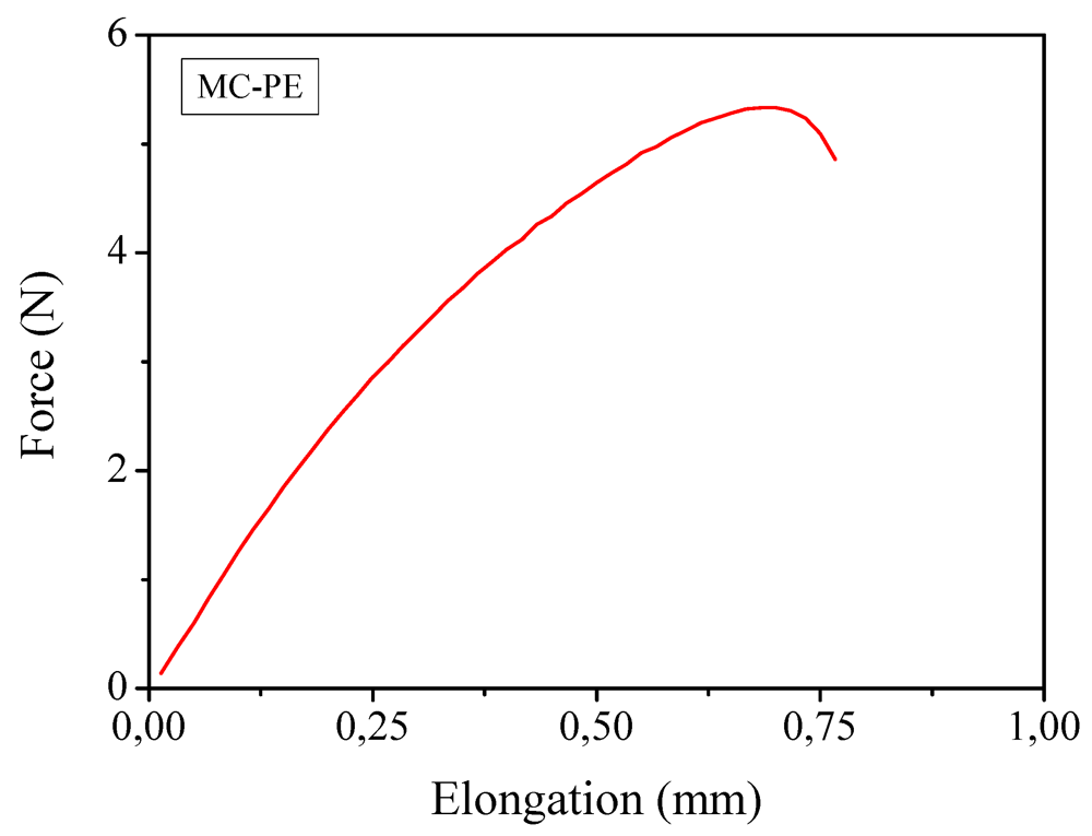
Tg was very low indicating that at ambient temperature the polymer membrane was in the rubbery state. Mechanical properties, obtained by means of tensile test studies revealed that the average Young’s modulus was 395 MPa and the average tensile strength was 2.3 MPa. A typical force-elongation curve is reported in
Figure 6. If one considers that the liquid content was calculated to be approximately 30 wt.%, these are very high values. It is important to note that, without cellulose reinforcement, the polymer electrolyte could not undergo this test. Such an excellent mechanical behavior is by all means a positive property: it may also improve the safety features of quasi-solid PE membranes, because the cellulose fibers could block the growth of lithium dendrites, as the cellulose fibers are highly crystalline and very strong.
Figure 6.
Mechanical measurements through traction test of the reinforced MC-PE at ambient temperature.
Figure 6.
Mechanical measurements through traction test of the reinforced MC-PE at ambient temperature.
The thermal stability of the reinforced polymeric film was assessed by thermo-gravimetric analysis under nitrogen flux. There was a distinct weight loss at approximate 120 °C, as the solvents began to evaporate: this means that the reinforced MC-PE can be safely used in thin flexible Li-based polymer batteries up to 100 °C.
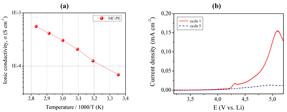
The ionic conductivity was evaluated by means of impedance spectroscopy and the Arrhenius plot is shown in
Figure 7, left layer (a). MC-PE demonstrated an acceptable ionic conductivity of about 6.8 × 10
−5 S cm
−1 at ambient temperature. It increased with increasing the temperature, resulting in 5.5 × 10
−4 S cm
−1 at 80 °C. All impedance spectra obtained in the selected temperature range were found to be linear, with no sign of high-frequency semicircles which could indicate lack of gel homogeneity due to crystalline phase separation.
Figure 7.
(a) Ionic conductivity versus temperature plot of the MC-PE reinforced quasi-solid polymer electrolyte. Data obtained by impedance spectroscopy; (b) Current vs. voltage curves at room temperature for MC-PE.
Figure 7.
(a) Ionic conductivity versus temperature plot of the MC-PE reinforced quasi-solid polymer electrolyte. Data obtained by impedance spectroscopy; (b) Current vs. voltage curves at room temperature for MC-PE.
In addition to high ionic conductivity, sample MC-PE showed an appreciable anodic breakdown voltage, which makes it particularly valuable in view of a practical battery application. This is shown in
Figure 7, right layer (b) which illustrates the current-voltage response of MC-PE obtained in the potential range between open circuit and 5.5 V
vs. Li at ambient temperature by linear sweep voltammetry. The plateau was very flat and straight; this very low residual current level prior to breakdown voltage, with no peaks in the lower voltage range, confirmed the high purity of the prepared sample and the synthesizing method adopted, because the system as a whole is sensitive to oxygen, water and other impurities. The increase of the current during anodic scan, which is related the decomposition of the electrolyte, was taken in correspondence to the onset of a low current peak at approximate 4.4 V
vs. Li. Nevertheless, if such low peak is not connected to the reaction of the electrolyte, then the stability range can be extended at least to 4.7 V
vs. Li, a really interesting value. Tests are being carried out to deepen this aspect.
In view of the possible practical application of the MC-PE reinforced polymer electrolyte, a laboratory scale Li cell was assembled by combining a lithium metal anode with a LiFePO
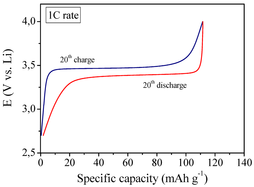
4/C cathode and using MC-PE as the electrolyte separator. Its electrochemical behavior was investigated by means of galvanostatic charge/discharge cycling at ambient temperature. The first results of galvanostatic cycling were found to be very interesting as depicted in
Figure 8 which shows the 20th galvanostatic charge and discharge profiles at 1C current regime. In fact, at 1C rate the cell was able to deliver a specific capacity of about 110 mAh g
−1, that is only about 12% lower with respect to the previously discussed not reinforced RC-1 polymer electrolyte membrane (see
Figure 5 at the same 1C current rate for comparison). Good performance at high current rate might be ascribed to the efficient ionic conduction in the polymer separator and the favorable interfacial charge transport between electrodes and electrolyte in the cell. The potential drop between the charge and discharge plateaus was small, which means low resistance of the cell. Moreover, the Coulombic efficiency was found to be almost 100%, thus indicating a good interfacial behavior between electrodes and reinforced polymer electrolyte during the charge/discharge cycles of the cell.
Figure 8.
Ambient temperature galvanostatic charge-discharge profiles of the lithium polymer cell assembled by sandwiching the MC-PE reinforced polymer electrolyte between a LiFePO4/C cathode and a Li metal anode, at 1C current rate.
Figure 8.
Ambient temperature galvanostatic charge-discharge profiles of the lithium polymer cell assembled by sandwiching the MC-PE reinforced polymer electrolyte between a LiFePO4/C cathode and a Li metal anode, at 1C current rate.
2.3. Composite Quasi-Solid Polymer Electrolyte Membranes Reinforced By Nanoscale Microfibrillated Cellulose Fibers
As demonstrated in the previous paragraph, the use of cellulose handsheets as a reinforcement for quasi-solid polymer electrolytes led to a remarkable increase of the tensile resistance, Young’s modulus and handling ability of the membranes but, on the other hand, caused a slight decrease of the ionic conductivity and overall performance in lithium cell. A cellulose handsheets consists of a matted of felted sheet of fibers, therefore the use of such a reinforcement clearly reduced the possibility of ionic conduction inside the membrane structure.
On the contrary, by using nanoscale microfibrillated cellulose (MFC) fibers this problem could be overcome without losing the positive impact of cellulose on the mechanical properties. MFC fibers consist of cellulosic individual nanoparticles with a lateral dimension of around 5 nm, which normally aggregate thus forming particles with lateral dimensions between 10 and 30 nm, or even higher. In length they can achieve few microns. MFC can form a highly entangled network with outstanding mechanical properties [
26]. Thus, the incorporation of MFCs as reinforcement was here proposed in order to combine the good ionic conductivity of the neat quasi-solid photo-polymerized polymer electrolytes with the excellent mechanical behavior of the reinforced membranes. The appearance of the composite quasi-solid polymer electrolyte, namely MFC-PE, obtained with the incorporation of 4 wt.% of MFCs, is shown in
Figure 1c. The composition of the polymeric matrix was the same as for the previously discussed RC-1 sample and the preparation method is discussed in Paragraph 3.4.
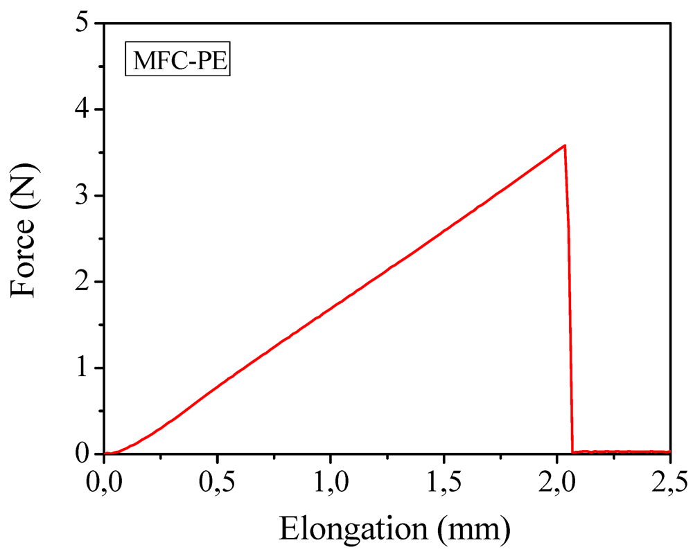
Mechanical properties obtained by means of tensile test studies on the polymer composites containing the liquid electrolyte (a typical force-elongation curve is reported in
Figure 9) gave an average Young’s modulus of about 32 MPa and an average tensile strength of approximate 2.0 MPa. The results were appreciable for the envisaged applications and more than satisfactory if considered that, in this case, the percentage of cellulose present in the membrane was highly reduced (from 10%–15% in the case of the previously discussed MC-PE to 4% of this MFC-PE). The outstanding handling ability, flexibility and bending endurance of the electrolyte membrane were proved also by means of bending test. To the purpose, sample MFC-PE was rolled around cylinders of diameter ranging between 32 and 3 mm and no sign of cracking was observed even when rolled around the cylinder with the lower diameter. Also in this case,
i.e., by using MFCs as reinforcing agent, such an excellent mechanical behavior may also help in improving the safety features of the PE membranes.
The thermal stability of the MFC-PE sample was assessed by thermo-gravimetric analysis under nitrogen. A distinct weight loss at approximate 110 °C was observed, as the solvents began to evaporate, meaning that the sample can be safely used up that temperature value.
Figure 9.
Mechanical measurements through traction test of the reinforced MFC-PE at ambient temperature.
Figure 9.
Mechanical measurements through traction test of the reinforced MFC-PE at ambient temperature.
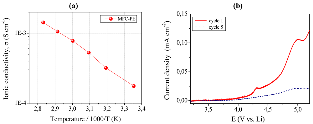
The ionic conductivity was evaluated by impedance spectroscopy and the Arrhenius plot is shown in
Figure 10, left layer (a). MFC-PE demonstrated an ionic conductivity of about 1.8 × 10
−4 S cm
−1 at ambient temperature, which increased at 80 °C resulting in the very interesting value of 1.4 × 10
−3 S cm
−1. Also in this case, all the impedance spectra obtained in the selected temperature range were found to be linear, with no sign of high-frequency semicircles. Such a reinforced quasi-solid polymer electrolyte membrane presented high ionic conductivity values, in fact almost comparable to those of RC-1 sample (see
Figure 3 for comparison).
Figure 10.
(a) Conductivity versus temperature plot of the MFC-PE reinforced quasi-solid polymer electrolyte. Data obtained by impedance spectroscopy; (b) Current vs. voltage curves at ambient temperature for MFC-PE.
Figure 10.
(a) Conductivity versus temperature plot of the MFC-PE reinforced quasi-solid polymer electrolyte. Data obtained by impedance spectroscopy; (b) Current vs. voltage curves at ambient temperature for MFC-PE.
MFC-PE also showed an appreciable anodic breakdown voltage, as shown in
Figure 10 left layer (b), which illustrates the current-voltage response obtained in the potential range between open circuit and 5.2 V
vs. Li at ambient temperature by linear sweep voltammetry. The plateau was observed to be flat and straight; this very low residual current level prior to breakdown voltage, with no peaks in the lower voltage range, confirmed the high purity of the prepared sample and the synthesizing method adopted which assured the complete removal of water despite the water-based MFC suspension used. As already discussed for sample MC-PE, the increase of the current during anodic scan, which is related to the decomposition of the electrolyte, was taken at the onset of a low current peak at approximate 4.3 V
vs. Li. If such low peak is not connected to the reaction of the electrolyte, then the stability range can be extended at least to 4.8 V
vs. Li, a really interesting value.
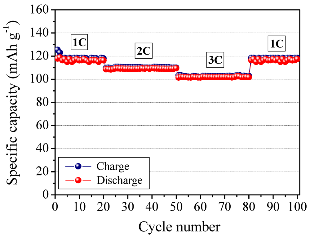
Finally, the MFC-PE composite polymer electrolyte membrane was assembled in a complete lithium polymer cell laboratory prototype using lithium metal as the anode with a LiFePO
4/C composite cathode, and its electrochemical behavior was investigated by means of galvanostatic charge/discharge cycling. The response of the prototype is reported in
Figure 11. It shows the specific capacity of the cell as a function of the cycle number at ambient temperature and at different C-rates (
i.e., 1C, 2C, 3C). The cell delivers an average specific discharge capacity of about 120 mAh g
−1 during the initial cycles, at 1C current rate. As the current density increased, the specific capacity decreased only slightly. Actually, at a high discharge rate of 3C, the cell was able to deliver an average discharge capacity higher than 100 mAh g
−1. That is comparable to the results obtained with the not reinforced RC-1 sample.
Figure 11.
Ambient temperature cycling performance of a LiFePO4/MFC-PE/Li polymer cell, at different C-rates, from 1C to 3C.
Figure 11.
Ambient temperature cycling performance of a LiFePO4/MFC-PE/Li polymer cell, at different C-rates, from 1C to 3C.
Good performance at high current rate might be ascribed to the efficient ionic conduction in the polymer electrolyte separator and the favorable charge transport at the interface between the electrodes and the electrolyte in the cell. The potential drop in passing from charge to discharge was observed to be small indicating a low resistance of the cell and high Coulombic efficiency (
i.e., approaching 100%). The specific capacity remained highly stable during the whole cycling test, with no sign of abrupt decay, indicating that the presence of cellulose fibers does not affect the cycling ability of the assembled polymer cell. Finally, it is important to note that the system behaves correctly, with no abnormal drift even at high regimes; in fact, reducing the C-rate completely restores the specific capacity (see, in
Figure 11, the specific capacity values from 3C to 1C after the 60th cycle). The results here demonstrate the feasibility of the MFC reinforced polymer electrolyte as a new electrolyte for advanced lithium polymer batteries.


