Article

Integration of Methane Steam Reforming and Water Gas Shift Reaction in a Pd/Au/Pd-Based Catalytic Membrane Reactor for Process Intensification

Center of Inorganic Membrane Studies, Department of Chemical Engineering, Worcester Polytechnic Institute, 100 Institute Road, Worcester, MA 01609, USA
*
Author to whom correspondence should be addressed.
Membranes 2016, 6(3), 44; https://doi.org/10.3390/membranes6030044
Submission received: 23 July 2016 / Revised: 2 September 2016 / Accepted: 9 September 2016 / Published: 19 September 2016
(This article belongs to the Special Issue Membrane and Process Intensification)

Abstract

:
Palladium-based catalytic membrane reactors (CMRs) effectively remove H2 to induce higher conversions in methane steam reforming (MSR) and water-gas-shift reactions (WGS). Within such a context, this work evaluates the technical performance of a novel CMR, which utilizes two catalysts in series, rather than one. In the process system under consideration, the first catalyst, confined within the shell side of the reactor, reforms methane with water yielding H2, CO and CO2. After reforming is completed, a second catalyst, positioned in series, reacts with CO and water through the WGS reaction yielding pure H2O, CO2 and H2. A tubular composite asymmetric Pd/Au/Pd membrane is situated throughout the reactor to continuously remove the produced H2 and induce higher methane and CO conversions while yielding ultrapure H2 and compressed CO2 ready for dehydration. Experimental results involving (i) a conventional packed bed reactor packed (PBR) for MSR, (ii) a PBR with five layers of two catalysts in series and (iii) a CMR with two layers of two catalysts in series are comparatively assessed and thoroughly characterized. Furthermore, a comprehensive 2D computational fluid dynamics (CFD) model was developed to explore further the features of the proposed configuration. The reaction was studied at different process intensification-relevant conditions, such as space velocities, temperatures, pressures and initial feed gas composition. Finally, it is demonstrated that the above CMR module, which was operated for 600 h, displays quite high H2 permeance and purity, high CH4 conversion levels and reduced CO yields.

1. Introduction

Methane steam reforming (MSR) is a well-established production method that currently generates 95% of hydrogen in the U.S. [1]. Conventionally, this reaction is carried out at high temperatures (700–1000 °C) and mild pressures (3–25 bar), which results in the production of CO and H2 with little CO2 as a byproduct. Carbon monoxide is reacted downstream in two, high- and low-temperature, water-gas-shift (WGS) reactors to further generate H2 and CO2. Equations (1)–(3) [2] show both chemical reactions where MSR is highly endothermic while WGS is exothermic. After the reaction, the purification of H2 is traditionally carried out in a pressure swing adsorption (PSA) unit. Notice that in the conventional process, both MSR and WGS reactions are limited by their thermodynamic equilibrium when carried out in customary packed bed reactors (PBRs).
MSR I  C H 4 + H 2 O C O + 3 H 2   Δ H 298 K = 206  kJ / mol
WGS  C O + H 2 O C O 2 + H 2   Δ H 298 K = 41  kJ / mol
MSR II  C H 4 + 2 H 2 O C O 2 + 4 H 2   Δ H 298 K = 165  kJ / mol
The application of membrane technology is economically attractive since it helps to reduce the number and size of equipment units needed, while simultaneously enhancing chemical conversions. The higher efficiency of the so-called catalytic membrane reactors (CMRs) results from the constant product removal from the reaction zone, through a selective membrane, altering the composition of the system. This change in composition allows accomplishing higher conversions, and it is often referred to as process intensification. Specifically, H2-selective membranes can improve MSR and WGS conversions while generating more hydrogen. Palladium-based membranes have been shown to be the best candidates for implementation in these processes since they can isolate hydrogen from gas mixtures in large quantities and at high purities while maintaining high stability and robustness. Ma et al. [3,4] have demonstrated the performance of different pilot-scale Pd and Pd-alloy membranes under industrial conditions. These membranes were capable of producing 1.16 kg/day of H2 with a purity of 99.89% under actual coal-derived syngas at 450 °C. Although a reduced H2 permeance was displayed due to the presence of contaminants, the stability, robustness and physical integrity of the membranes were successfully demonstrated.
In the case of CMR technology, the literature has shown membrane application up to a pilot-scale magnitude [5], as shown in Table 1. Palladium membranes are capable of operating at temperatures between 300 and 600 °C, matching the temperatures of high-temperature WGS catalysts (310–450 °C). A low-temperature WGS unit is no longer needed, since high CO conversions can be achieved through a single CMR unit. Furthermore, the effect of process intensification in MSR allows operating this process at mild temperatures (Table 1) while maintaining high conversions, preventing coking and reducing the CO yield. The experimental tests shown in the literature demonstrate the effect of process intensification; nevertheless, the scale of operation is relevant for the industrial deployment of this technology. Few pilot-scale tests have been published in this field, including the work presented by Catalano et al. [6], where 5.6 m3 of H2 per day were produced through a WGS membrane reactor at 440 °C and 20 bar. Furthermore, Patrascu et al. [7] showed the performance of methane steam reforming (MSR) in a large-scale CMR achieving a permeate flux of 1.6 NL/min at a temperature of 525 °C and a pressure of 10 bar and utilizing a membrane with a surface area of 175 cm2. Furthermore, economically, CMR technology has shown success when integrated in power and hydrogen production plants. Kazantzis et al. reported the specific market and regulatory conditions under which Pd-based CMRs can be successfully integrated in the pertinent energy systems [8,9].
This work aims to implement the integration of one more processes into a single unit. Specifically, the operation of a large-scale Pd-based CMR module is shown where both MSR and WGS reactions are integrated in a single unit, in order to provide high CH4 yields with little or no CO. In the CMR, the first catalyst (MSR) is confined on the shell side of the reactor, while the WGS catalyst is positioned subsequently in series. A tubular Pd/Au/Pd membrane situated throughout the reactor continuously removes the H2 to yield higher conversions. The higher shell pressure facilitates the acquisition of clean pressurized CO2 and water, while ultrapure H2 is obtained in the permeate stream. Furthermore, for comparison, the reaction is carried out in a conventional packed bed reactor for both configurations: MSR and multistage MSR-WGS (five layers). Additionally, a two-dimensional computational fluid dynamics (CFD) model was developed in order to further analyze the properties of this unit. Please notice that the aim of this work is a proof-of-concept approach that explores the potential use of catalysts packed in series and/or in parallel to enhance conventional processes.
This work is structured as follows: Section 2 presents the methodological framework, as well as an explicit description of the experimental procedure and CFD development. Section 3 encompasses the results associated with the conventional reactors and the CMR’s performance characteristics along with the pertinent simulation results accompanied by a thorough discussion related to the effect of coupling two catalysts in one unit. Finally, some concluding remarks are offered in Section 4.

2. Methodology

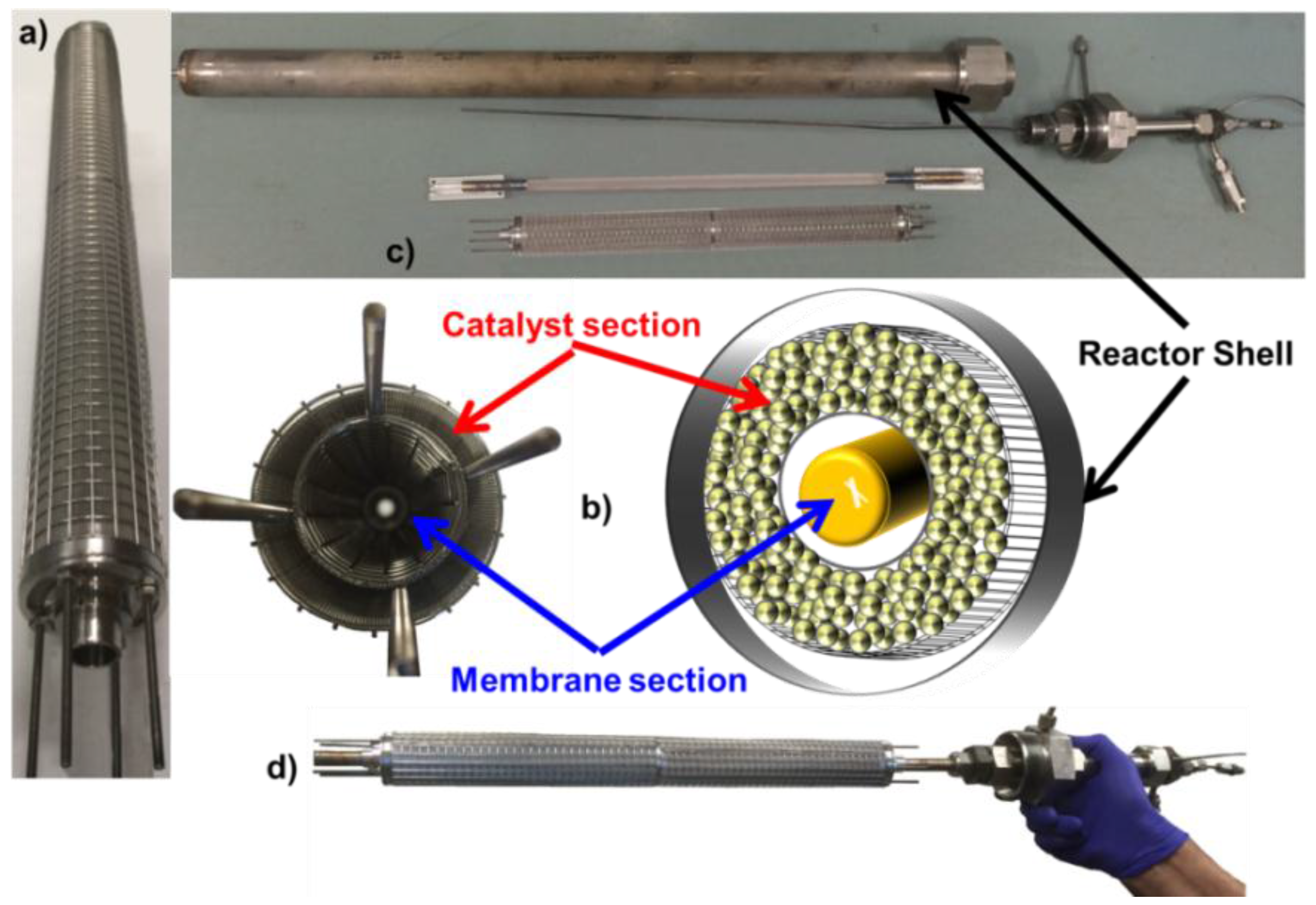
2.1. Membrane Fabrication

A composite Pd/Au/Pd membrane was prepared on a 1.27-cm OD and 38.1-cm in length 316-L porous stainless steel (PSS) support with media grade of 0.5 μm. The total permeable area of the membrane was 152 cm2. One end of the membrane was welded to a 316-L nonporous capped tube while the other end was welded to a nonporous tube. The support showed an initial He flux of 200 L/min at a pressure difference of one bar. To synthesize the membrane, the support was first covered with sol-gel and then calcined at 600 °C for 12 h. After calcination, the supports were graded following a previously-reported procedure with medium and fine pre-activated powder, provided by Johnson Matthey (Royston, UK), based on a 2 wt % Pd-alumina catalyst without any additional activation or treatment [23,24,25]. Notice that the grading procedure reduced the He leak across the membrane by 3 orders of magnitude, as shown in Table 2. After grading, the surface of the membrane was activated with SnCl2-PdCl2, and then, electroless plating was used to deposit a dense Pd layer. A thin gold layer of 0.2 μm was deposited on top of the palladium surface via conventional electroplating. Notice that gold has been shown to enhance the properties of Pd-based membranes, such as permeance, stability and contaminant-recoverability [26], and therefore, was used in this work. Finally, to provide active sides on this asymmetric membrane and further reduce the He leak present, a pure Pd topmost layer was deposited. The thickness of the membrane was estimated by gravimetric methods. The final composition and leak of the membrane was 6.9 Pd/0.2 Au/3.2 Pd and <0.01 sccm/bar, respectively. The thicknesses and He leak at each step of the synthesis are shown in Table 2.

2.2. Reaction Tests and Membrane Characterization

The H2 permeation tests and reactions were performed in the same WGS-CMR rig previously reported by Catalano et al. [6]. The composition of the feed was controlled by mass flow controllers and premixed with steam generated in a preheater. The wet mixture was fed to the reactor, which contains the membrane surrounded by the catalysts. The catalysts used for MSR and WGS were a nickel-based catalyst (HiFUEL R110, Alfa-Aesar, Lancashire, UK) and an iron-chrome catalyst (HiFUEL W210, Alfa-Aesar), respectively; these catalysts were crushed and sieved (16/+40 mesh) before usage. The water of the retentate was condensed, while the product and retentate flow rates were passed through water absorbent beds before the composition was measured by mass flow meters and a gas chromatograph [6]. Three main experiments were conducted on the CMR-rig, including: (i) MSR in a conventional packed bed reactor (PBR); (ii) multi-staged (5 layers) MSR/WGS in a PBR; and (iii) MSR/WGS in a CMR. It is important to note that no sweep gas was utilized in any of the experiments presented in this work.
For the CMR reaction, a protective cage was designed in order to prevent any potential damage of the membrane caused by the friction of the catalyst particles and the wall of the membrane, as previously reported in the literature [22,27]. The cage was made out of stainless steel grids, and it consisted of two concentric confines; one surrounded the membrane, while the other was used to hold the catalyst in place, as shown in Figure 1b. Notice that the surface of the membrane was never in contact with the grid of the cage. The catalyst section of the cage had a volume of 480 cm3, and it was filled with 120 g of MSR catalyst and 120 g of WGS catalyst for the membrane reactor, while the PBR was packed in 5 sections. This membrane-catalyst cage system can be up-scaled in order to develop multi-tube CMR modules.

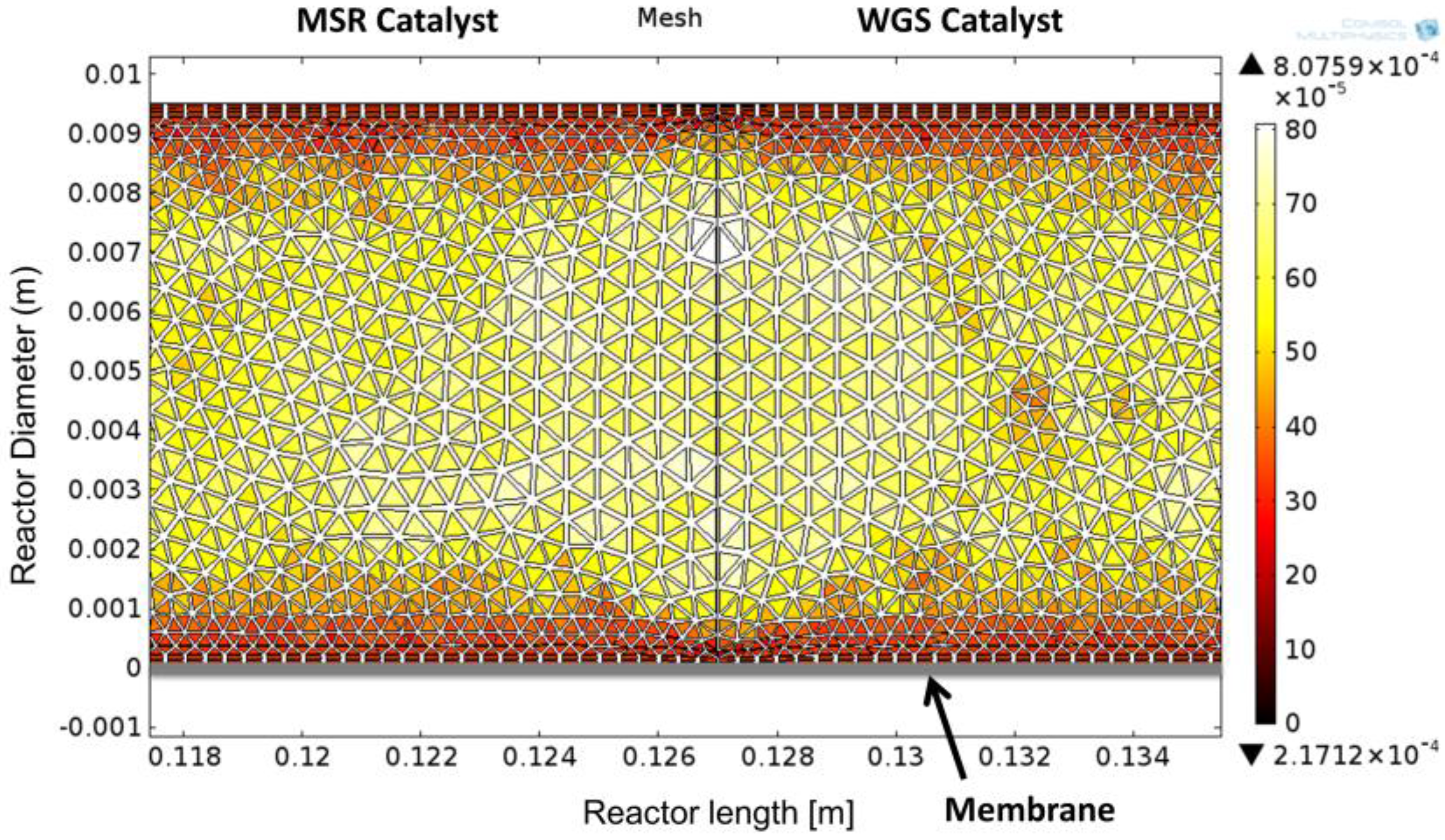
2.3. Mathematical Modeling Framework

A detailed modeling framework, helpful for the analysis of CMRs, has been used for the interpretation of data [5], and accordingly, a 2D computational fluid dynamics (CFD) model was developed in COMSOL Multiphysics 4.3b (COMSOL, Inc., Burlington, VT, USA) in order to examine the properties of the module and compare theoretical values with experimental results. A 2D configuration of the model was chosen in order to include the non-ideal flow effects that occur in the reactor due to the axisymmetry of the reactors. The performance of the simulation was compared against the experimental values obtained in this work and, for MSR, against the 1D model presented by Ayturk et al. [2], where a 99.4% accuracy was found when compared to other literature sources, including conventional PBRs and CMRs. Figure 2 shows the configuration of the 2D model, where the MSR catalytic section is located adjacent to the feed flow stream, followed by the WGS section upstream; the membrane was specified to be at the bottom, taking advantage of the symmetrical configuration of the reactor module; additionally, the mathematical mesh, displayed in Figure 2, is used to solve the momentum and continuity equations for the retentate side (Equations (4)–(6)) (COMSOL Multiphysics). The Darcy–Forchheimer law was applied in the present model accompanied by the following assumptions:
(1)
Isothermal conditions;
(2)
Steady state;
(3)
Laminar flow;
(4)
Non-slip boundary condition for the fluid flow;
(5)
Negligible effect of the protective cage on the flow pattern.
The modified Navier–Stokes equation for a fixed bed porous medium is:
ρ ε p ( ( u · ) u ε p ) = · [ pI + μ ε p ( u + ( u ) T ) 2 u 3 ε p ( · u ) I ] ( μ k 1 + β F | u | ) u + F
where ε p represents the system porosity and β F is the Forchheimer coefficient:
· ( ρ u ) = 0
· ( D i c i ) + u · c i = R i
The reaction rates for MSR were specified as [2]:
r 1 =   k 1 P H 2 2.5 × P CH 4 P H 2 O ( P H 2 3 P CO / K 1 ) DEN 2
r 2 =   k 2 P H 2 × P CO P H 2 O ( P H 2 P CO 2 / K 2 ) DEN 2
r 3 =   k 3 P H 2 3.5 × P CH 4 P H 2 O 2 ( P H 2 4 P CO / K 3 ) DEN 2
where DEN is defined as:
DEN = 1 + K CO P CO + K H 2 P H 2 + K CH 4 P CH 4 +   K H 2 O P H 2 O P H 2
Notice that r1, r2 and r3, correspond to the reactions specified in Equations (1)–(3), respectively. Refer to the previous literature for the kinetic, adsorption and equilibrium constants [2]. Furthermore, the reaction rate used for the WGS reactor model over Fe-Cr-based catalyst was specified as [28]:
r 4 =   10 2.845 · e 111 Rg · T · P CO 1.0 P CO 2 0.36 P H 2 0.09 · [ 1 P H 2 P CO 2 K   P H 2 O P CO ]
where K is the equilibrium constant.
The reaction model is homogenous as the internal effectiveness factor was calculated to be 1. The internal effectiveness factor is defined as the actual rate of reaction divided by the rate of reaction that would occur if the entire internal surface of the catalytic particle would be exposed to the external conditions.
Additionally, the flux across the membrane ( N i ) was based on Sieverts’ law as follows [2,29]:
N i =   P H 2 ¯ ( P H 2 Shell P H 2 Tube )
where P H 2 Shell   and P H 2 Tube   represent the hydrogen partial pressure at the retentate side and the permeate side, respectively, and P H 2 ¯ is the permeance of the membrane obtained experimentally. Furthermore, the calculation of binary fluid diffusion coefficients ( D m ) was estimated according to standard engineering procedures [30]:
D m =   0.0018583 T 3 ( 1 M A + 1 M B ) 1 P σ AB 2 φ D , AB
where M i is the molecular weight of component i, P is the pressure of the system, σ AB 2 denotes the parameters of the Lennard–Jones potential between molecules A and B and φ D , AB represents the collision integral for diffusion.
The longitudinal and transversal dispersion DL and DT are calculated using the equations below [31]:
Pe m = d · u D m
1 / Pe L   = 1 / ( τ · Pe m ) + 1 / 2
1 / Pe T   = 1 / ( τ · Pe m )   + 1 / 12
D L = u · d / Pe L
D T = u · d / Pe T
where Pe m ,   Pe L and Pe T are the molecular Péclet number, the longitudinal Péclet number and the transversal Péclet number, respectively; τ denotes tortuosity, and d represents the catalyst particle diameter.
The conversion of methane was defined as [2]:
X conversion =   F CH 4 , feed F CH 4 , ret F CH 4 , feed

3. Results and Discussion

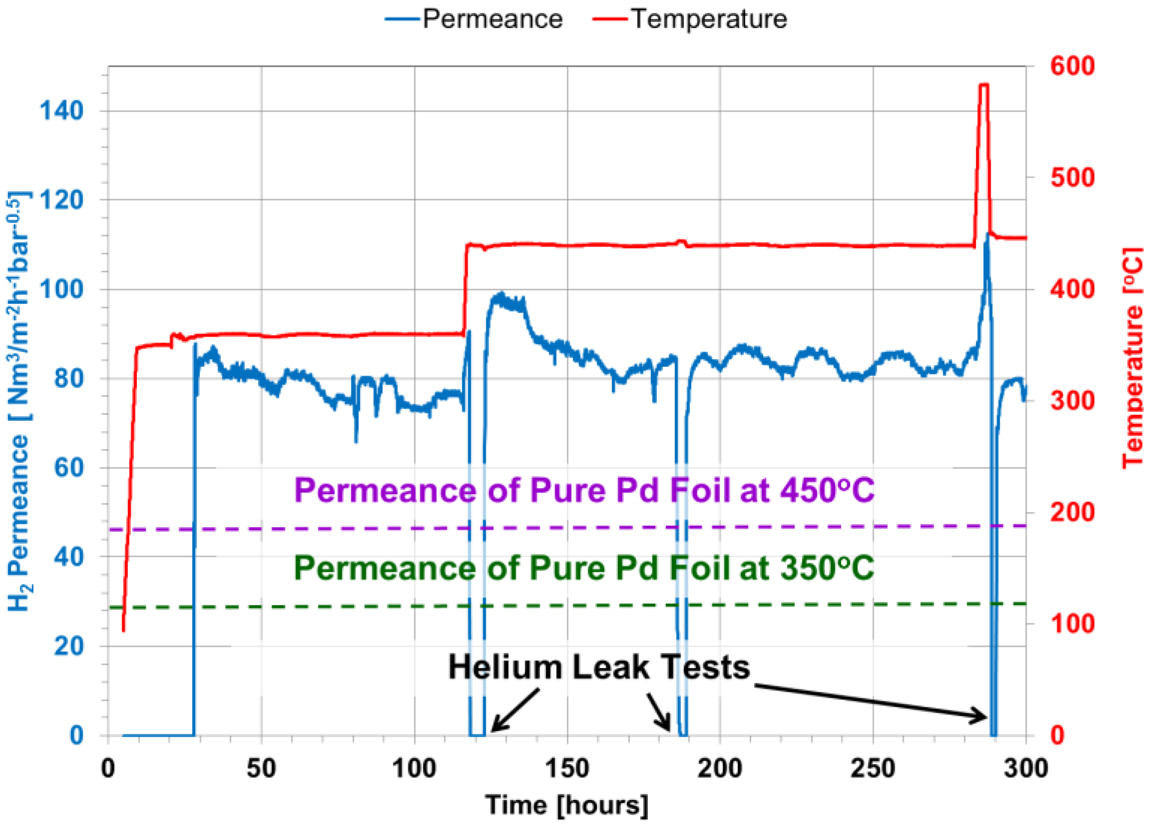
3.1. He Leak Tests and H2 Permeation Tests of the Membrane

After the module was installed in the CMR rig, the temperature of the membrane module was increased from room temperature to 350 °C under He gas at a rate of 1 °C/min and a pressure of 2 bar. At this temperature, a helium leak test showed an undetectable leak, and H2 was introduced to the module. Hydrogen permeance was measured as a function of time continuously every 30 s as shown in Figure 3. After 80 h, the temperature was increased to 450 °C, displaying a slight increase in H2 permeance. The temperature was kept for 160 h, and two helium leak tests were performed displaying undetectable He leak. Notice that on the first He leak test, steam was fed to the system along with He for one hour to fully oxidize the WGS catalyst. The membrane showed a H2 permeance of 70 and 80 Nm3·m−2·h−1·bar−0.5 at 350 and 450 °C, respectively. After 290 h of continuous testing, the module temperature was increased to ~600 °C under a pure H2 stream for 3 h to activate the MSR catalyst. Notice that after activation, the membrane presented a He leak of 0.4 sccm/bar at 450 °C. The asymmetric Pd/Au/Pd membrane showed high H2 flux and an ideal H2/He selectivity of over 4300 after the catalyst was activated. Even though it has been shown that to improve the thermal stability of the membranes, porous Hastelloy and Inconel supports perform better than PSS at temperatures higher than 500 °C [32], the membrane showed a high thermal stability.
Moreover, Gade et al. [33] showed that unannealed Pd-Au membranes require ~300 h under typical operating conditions to fully anneal in situ the Pd-Au surface of the membrane and consequently reach a steady H2 flux. Nevertheless, as shown in Figure 3, after H2 feed was introduced into the system at 350 °C, the H2 flux across the membrane reached a steady state very quickly. This effect could be the result of plating Pd on top of the Au surface, which added active sites for the permeance to occur.
Pure Pd membrane foils have shown a H2 permeance that follows the Arrhenius correlation, as shown in Equation (20), where t is the thickness of the membrane in μm, 15,630 is the activation energy in J/mol and 6322.7 is the pre-exponential factor in m3·μm·m−2·h−1·atm−0.5 [2]. Furthermore, considering that the presented Pd/Au/Pd membrane has a Pd layer of 10.1 μm, the expected permeance of its pure Pd foil analog is 47 Nm3·m−2·h−1·bar−0.5 at 450 °C. It is important to mention that the hydrogen permeance of the presented Pd/Au/Pd membrane is superior by a factor of 1.7. This enhanced behavior of the membrane is due to the presence of gold, which as previously reported [3,34] can raise the permeance up to two-times higher due to an increase in diffusivity. Although the amount of gold in the presented membrane is 2%, which is below the optimum 5% [35], the membrane displayed an excellent and stable H2 flux.
P H 2 ¯ = [ 6322.7   e 15630 R T ] t

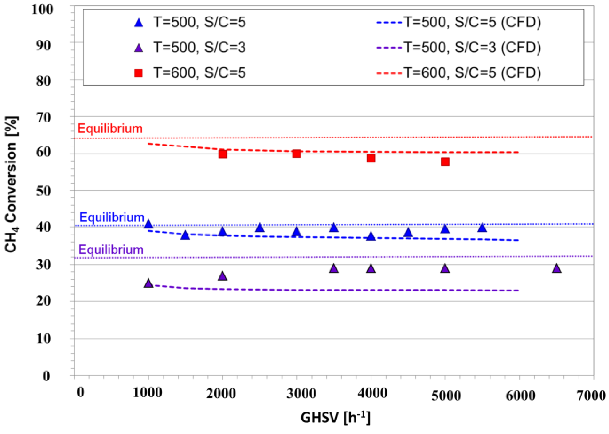
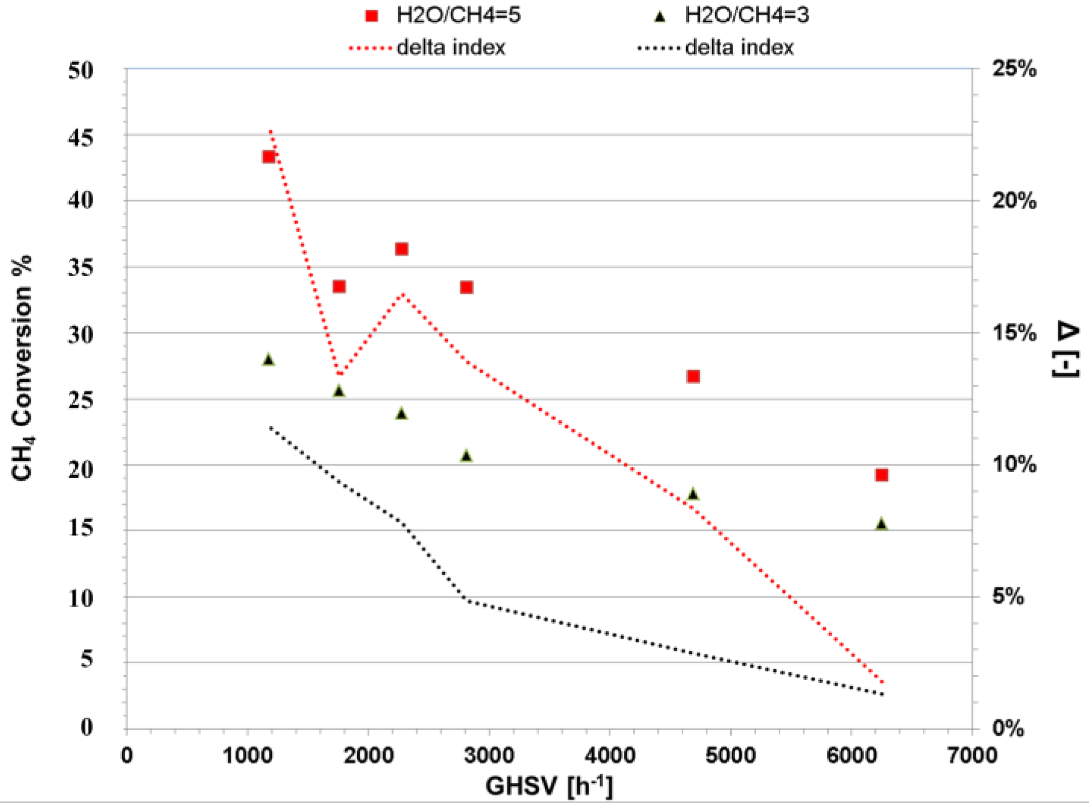
3.2. MSR in a Conventional Packed Bed Reactor: Single Catalyst

Methane steam reforming was carried out in a conventional packed bed reactor (PBR) to experimentally demonstrate the effect of process intensification and the presence of the secondary catalyst. As mentioned before, the major advantage of the CMR compared to a conventional PBR is the conversion enhancement of the equilibrium-limited MSR by removing in situ the produced H2. Therefore, in order to study the performance of a PBR, a solid stainless steel pipe was placed instead of the membrane in order to maintain identical geometric features of the CMR reactor. As shown in Figure 4, different space velocities, temperatures and steam-to-carbon ratios were used to investigate the performance of the PBR; all reaction conditions were set to a total pressure of 2 bar, since higher pressures did not show significant changes in the reaction performance. Notice that the catalyst loading was arranged in such a way that the operating GHSV was of 5000 h−1 as specified by the provider of the catalyst. Furthermore, the experimental results were graphically depicted along with the computational simulation outcomes as shown in Figure 4.
We examine the performance of the PBR by analyzing its methane conversion at 500 °C and a steam-to-carbon ratio of three. It is observed that even at small space velocities, methane conversion is below its chemical equilibrium (shown as a dotted line in Figure 4); this effect is caused by the reduction of the contact time of methane with the catalyst. Furthermore, the effect of temperature on the conversion of methane is clear; it increased from 40% to 60% when the temperature of the reactor was increased from 500 to 600 °C. This is in agreement with the fact that MSR is an endothermic reaction, which is highly favored by high temperatures.
Additionally, adding steam has a positive effect on the reaction, doubling the conversion when the steam-to-carbon ratio is increased from 3 to 5. Furthermore, excess steam is generally present in the MSR process, since it not only increases conversion, but also prevents coke formation. It is important to mention that the results presented in this work are similar to the results reported in the pertinent literature [2,36]. Additionally, the CFD simulation results, shown in Figure 4, match the experimental data with an average error of 7.8%. The experiments were carried out in a pilot-scale module, and therefore, these results were more susceptible to divergence from controlled settings.

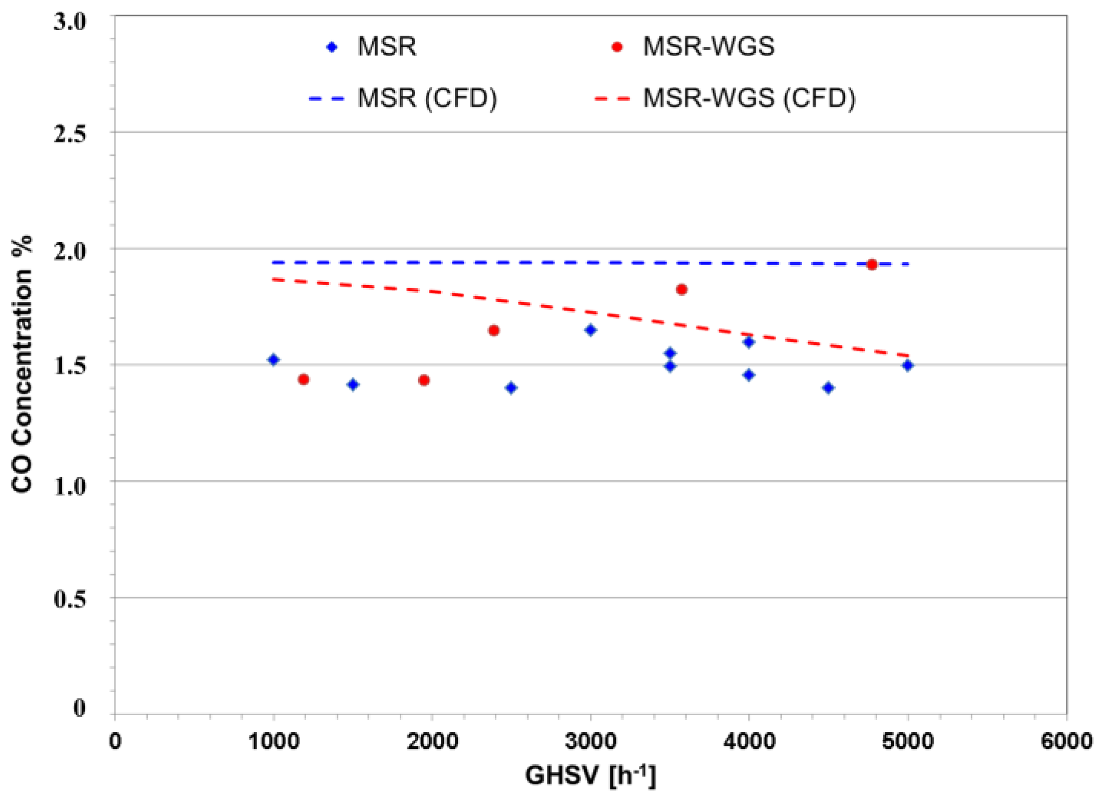
3.3. MSR/WGS in a Conventional Packed Bed Reactor: Dual Catalyst

The reforming of methane and the water gas shift reactions were studied in a conventional packed bed reactor (PBR) to demonstrate the effect of the secondary catalyst and thus effectively demonstrate the presence of a membrane. The reactor was packed in stages while a solid stainless steel pipe was used instead of a membrane in order to maintain the geometry of the module, as shown in Figure 5. The PBR was packed in series with a fresh Ni-based reforming catalyst and a Fe-Cr-based WGS catalyst with an overall proportion of 20% and 80% for reforming and WGS, respectively. The configuration of the catalysts within the reactor, shown in Figure 5, was split as MSR-WGS-MSR-WGS-MSR. The MSR-WGS reactor was tested at 475 °C since the Fe-Cr catalyst temperature limit is specified by the provider to be of 500 °C. After packing the module, steam and He were fed to the system to oxidize the WGS catalyst. The catalyst emitted H2, and therefore, oxidation continued until H2 was not detectable by the GC [6]; this process took around 1 h. Afterwards, the temperature of the module was increased to ~600 °C under pure H2 stream for 3 h to activate the MSR catalyst. After these procedures, the reaction tests were carried out. Notice that a CFD simulation for this multistage packing configuration was performed to further analyze the PBR.
The conversion of methane at 475 °C, 2 bar and a GHSV of 3500 h−1 was found to be 18%, as shown in Figure 6; however, it decreased slightly as the pressure was increased. It is important to mention that the purpose of adding the WGS catalyst is to prevent or reduce the formation of CO in the module. As shown by Figure 6, it can be observed that although in small quantities, CO is present in the product of the reaction. For both experiments and simulations, the amount of CO reduces as pressure increases; this indicates that the production of CO may be hindered by pressure or that the activity of the WGS catalyst is favored at higher pressures (Equation (2)). Given the stoichiometry of MSR (Equations (1)–(3)), a reduction of methane conversion and simultaneously CO generation as the pressure of the reactor increases is expected; at the same time, as reported by Atwood et al. [37], the WGS reaction intensifies at higher pressures. These two mechanisms contribute to obtaining lower CO yields.
It is important to notice that in this dual-catalyst reactor, the WGS reaction occurs in the presence of a significant amount of H2, which limits its performance. Figure 7 shows that even though lower theoretical CO is present in the dual-catalyst reactor, the experimental results of the pilot-scale bed appeared to be hindered by the intrinsic error in the measurements. Nevertheless, through the simulation, it is found that as the space velocity increases, the difference in CO production decreases further for the dual-catalyst bed. This effect can be attributed to two factors: (i) the reduced presence of H2; and (ii) lower concentrations of CO. The aforementioned factors are generated due to reduced CH4 conversions. Additionally, a surface plot of CO concentration through the reactor module is shown in Figure 8 to illustrate the effect of the water-gas-shift catalyst. At first, CO is generated on the first MSR catalyst bed section, followed by its consumption by the WGS reaction zone. The next MSR layer induces the production of more CO, which is later reduced by the following WGS segment. Finally, the MSR catalyst at the end of the PBR increases the overall CO concentration inside the reactor.

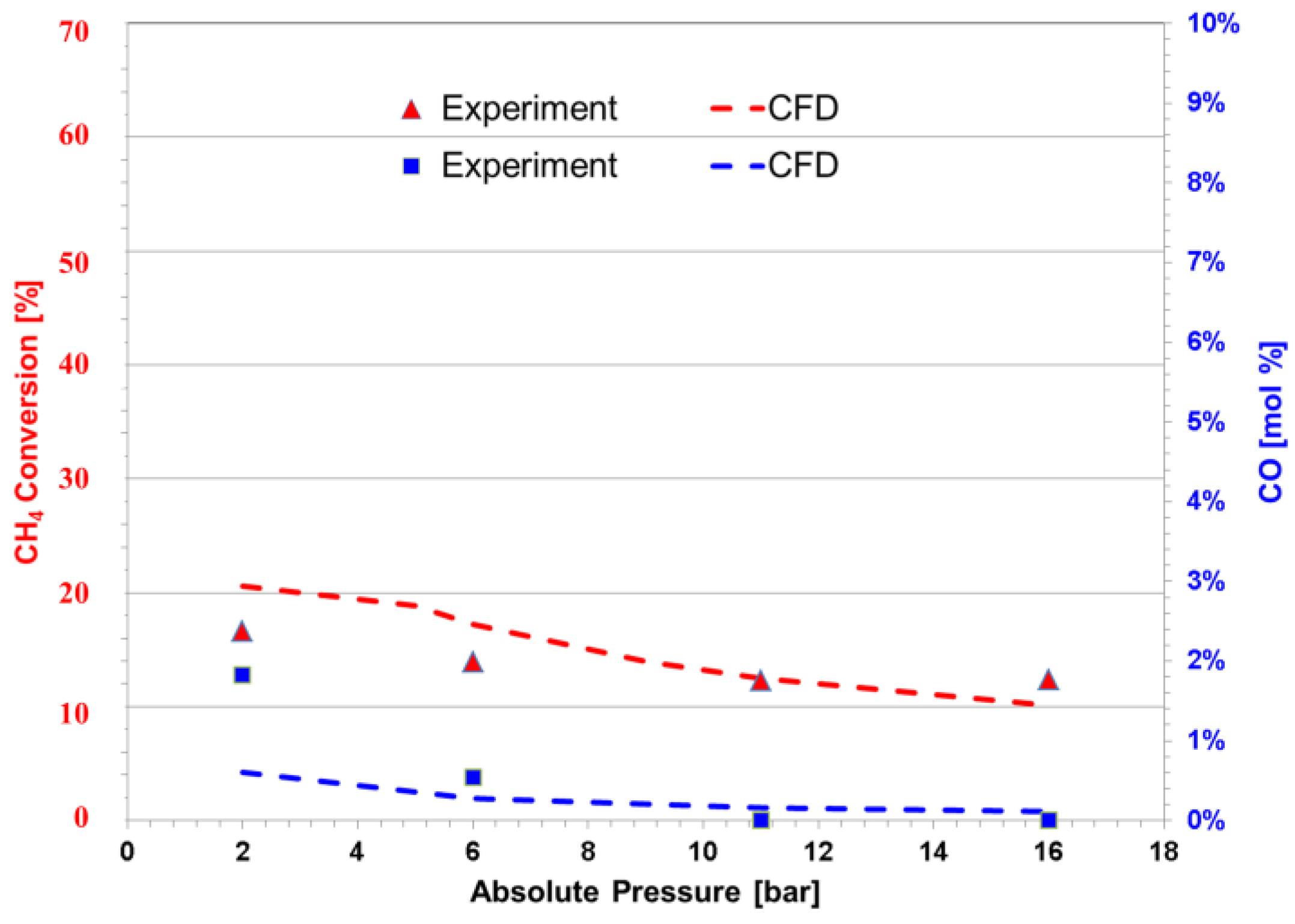
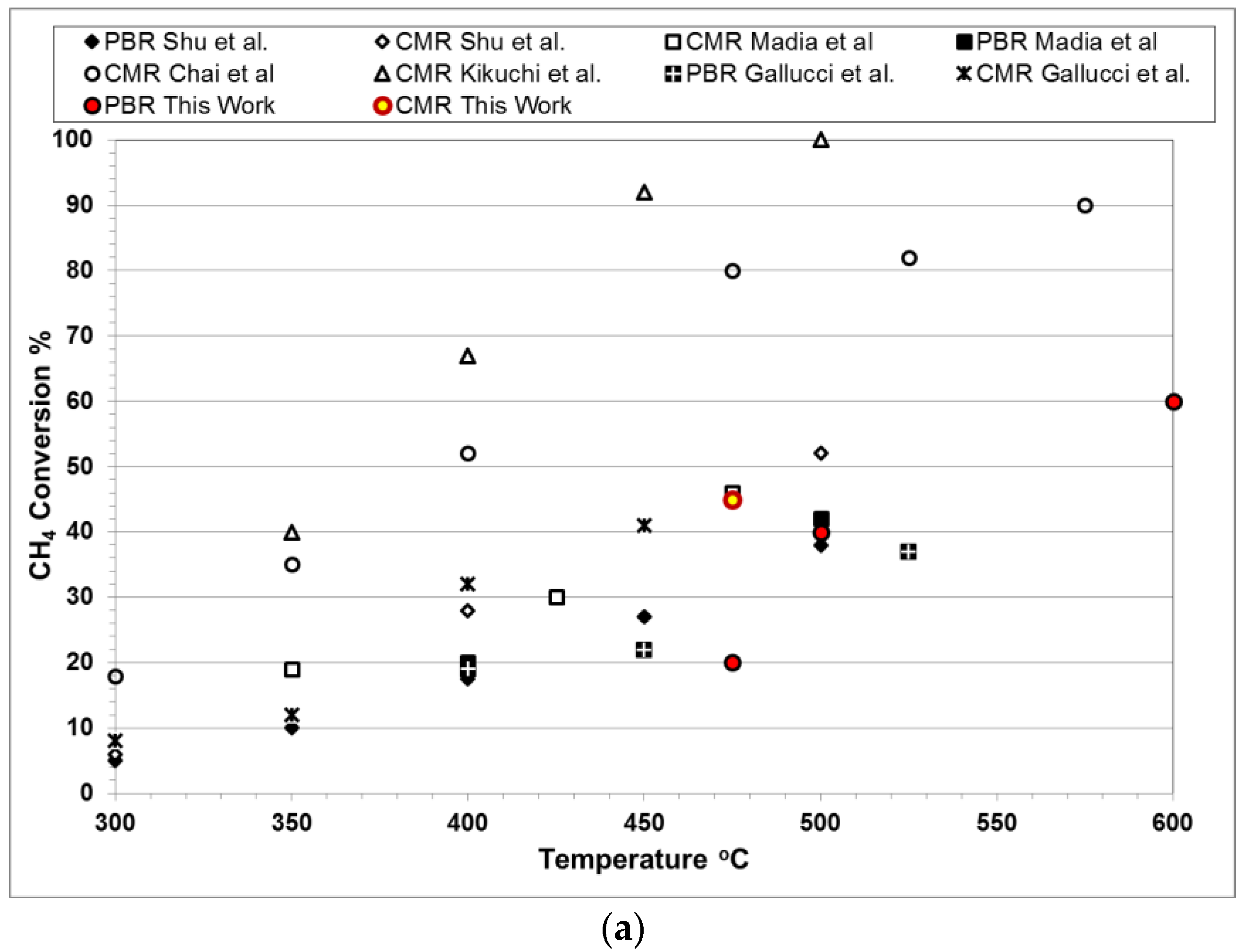
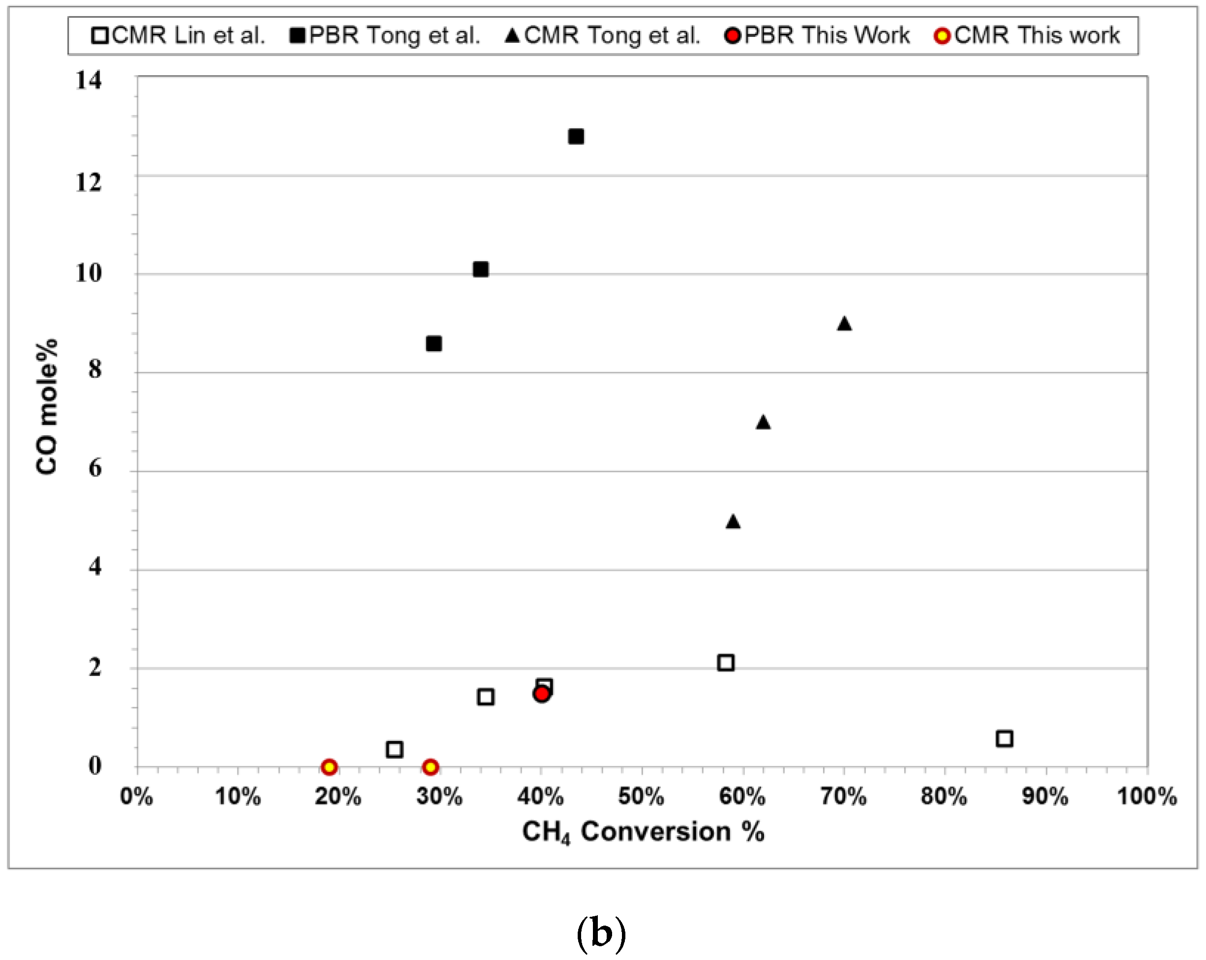
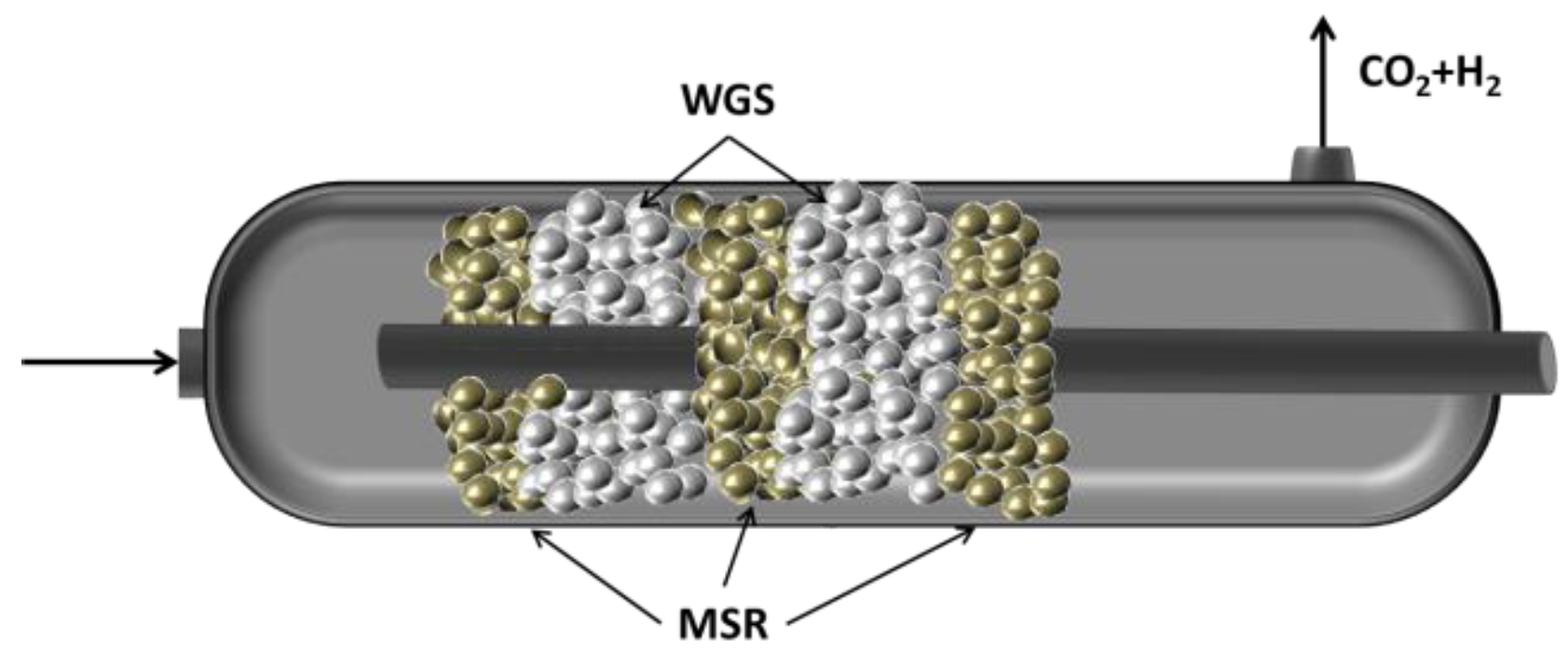
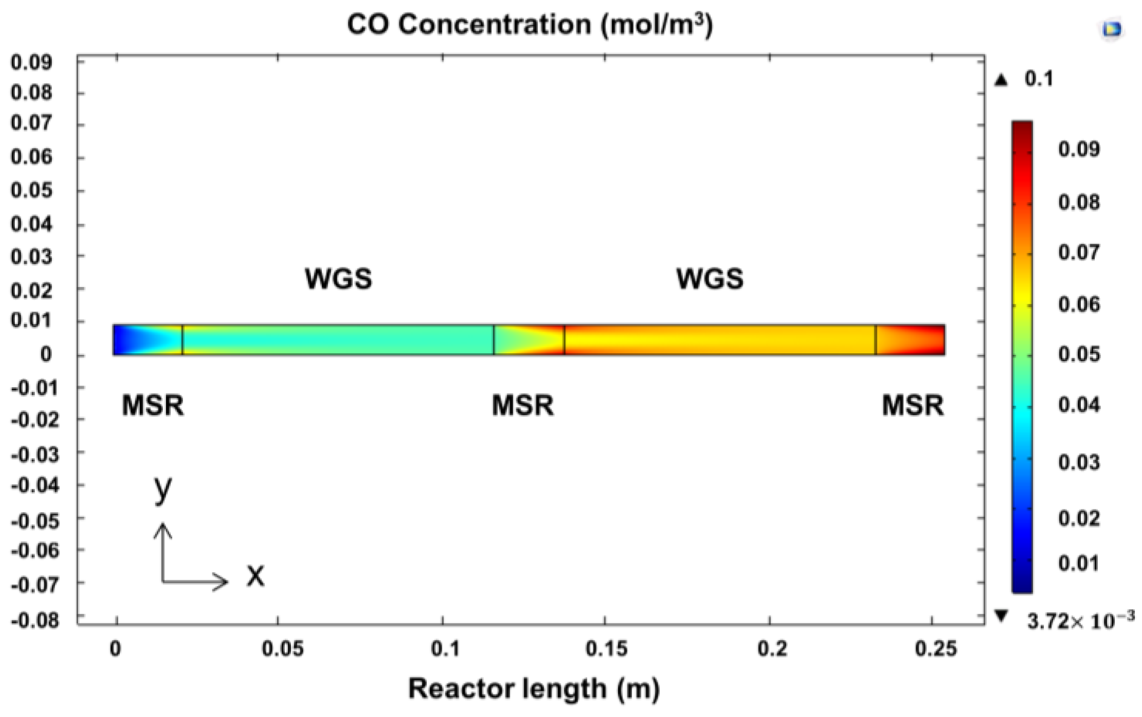
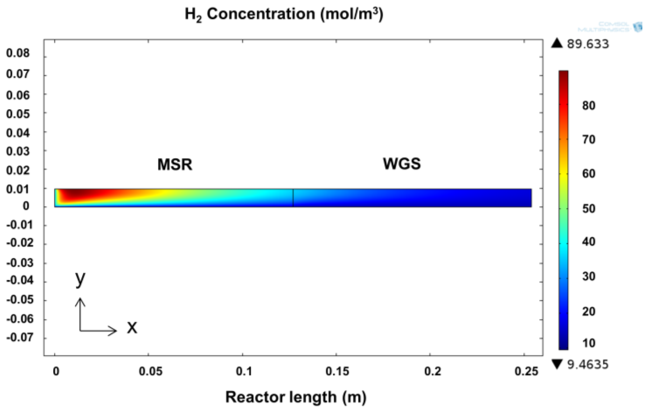
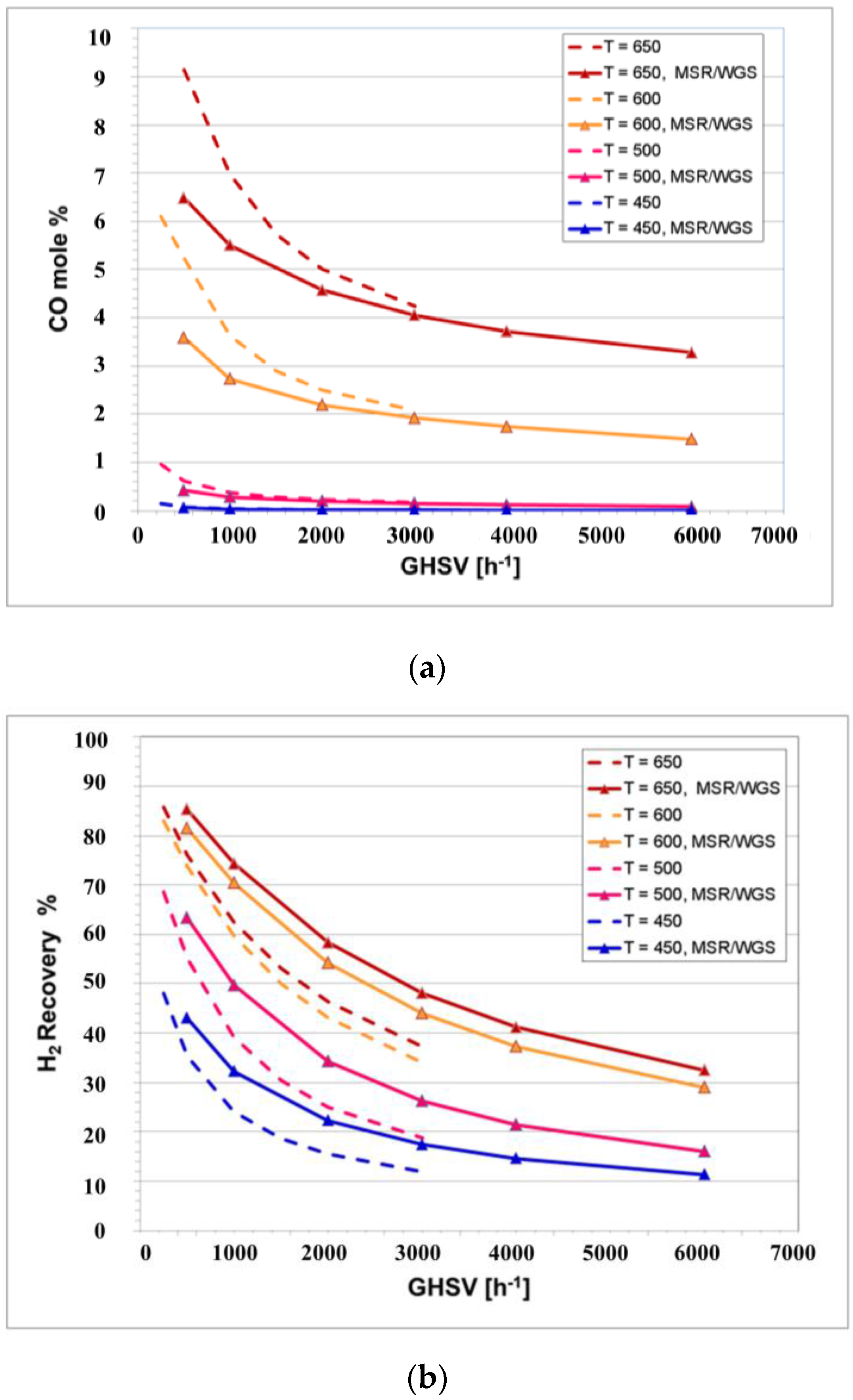
3.4. MSR/WGS in a Catalytic Membrane Reactor

The CMR was packed with two layers of catalysts in series only (in contrast with the five layers in the PBR) and with a membrane placed at the center of the reactor to remove in situ the H2 generated by the reactions. The experimental CH4 conversion results are shown in Figure 9 for different steam-to-carbon ratios, a temperature of 475 °C and a pressure of 5 bar. Notice that, in contrast with conventional PBRs, the pressure has a significant effect on the effectiveness of CMR technology. Since the rate of removal of H2 is a function of its partial pressure, higher pressures will ensure a better performance. Furthermore, the CMR in this reactor was not tested at 2 bar (as the PBR); because at such a low pressure difference, it is expected to observe reverse flow (from the permeate side to the reacting side) since H2 is pure on the permeate side. The highest conversion achieved was of 43.3% at a steam-to-carbon ratio of five and a space velocity of 1172 h−1. Furthermore, it is found that as the GHSV was increased, the conversion of methane decreased accordingly; this was caused by the reduction of residence time in the reactor. In addition, the amount of water influenced the reaction significantly; a steam-to-carbon ratio of five produced about 20% higher CH4 conversion than a ratio of three. Notice that the H2 purity generated by this Pd/Au/Pd membrane was 99.94% throughout a testing time of 350 h under MSR/WGS conditions. The best flux achieved by the CMR under optimum conditions was over 500 NL/day. After the experiments were terminated, the surface of the membrane did not show carbon deposition for the reason that the protective cage separated effectively the reaction zone from the membrane.
The reactor performance indicator for process intensification was quantitatively analyzed based on the Δ-index previously reported by Ayturk et al. [2]. This index is represented in Equation (21) as the difference between the CH4 conversion achieved by the CMR and the one by PBR under similar conditions.
Δ   =   X C H 4 C M R   X C H 4 P B R
It is important to mention that the PBR was not operated experimentally at 475 °C and 5 bar; consequently, the CFD performance outcome of the conventional PBR was utilized to estimate the Δ-index of this work. The Δ-index represented in Figure 9 shows that at all GHSV, the conversion of methane increases when sized against a conventional reactor. Nevertheless, the concept of process intensification is better appreciated at low space velocities since H2 has a better rate of removal and the contact time of the gases with the catalysts increases.
For the simulation result, as expected, compared to a PBR, the constant removal of H2, shown by the hydrogen concentration profiles in Figure 10, changes the composition of the retentate, allowing both reactions to proceed further. In Figure 10, it is possible to observe that as soon as the feed stream (on the left) is in contact with the catalyst bed, H2 is generated and increases as the reaction proceeds; this continues until the H2 partial pressure in the retentate is high enough to provide the driving force for the membrane to start removing it. Notice that even though the reaction continues to take place in the module, an increase in H2 concentration is no longer observed; this effect is caused by the rate of removal overcoming the rate of reaction. Furthermore, it is possible to observe, from top to bottom, a gradual reduction in H2 concentration caused by the presence of the membrane. This reduction in H2 concentration adjacent to the surface of the membrane causes a H2 depleted boundary layer formed by low radial diffusion rates. This effect is often referred to as concentration polarization, and it can significantly reduce the performance of the membrane [38].
To further characterize the performance of the membrane reactor, the product of Damkohler and Péclet numbers (DaPe number) is utilized, since it provides the ratio of maximum reaction rate over the maximum permeation rate per volume [39]. In PBRs, the Damkohler number (Da) exemplifies the performance of the reactors, since it shows the ratio of the reaction rate over the convective mass transport of the reactant; while in membrane technology, the Péclet number shows the relative convection transport rate over the diffusive rate (permeation). Consequently, the product DaPe dictates the overall effectiveness of the CMR; for instance, having a DaPe > 1 means that the permeation rate is low, and thus, the H2 rate of removal through the membrane is the limiting factor of the reactor’s productivity. As reported by Battersby et al. [39], the DaPe number can be estimated as shown in Equation (22) where Xequilib is the conversion achieved when the reaction is thermodynamically at equilibrium, and Xactual is the conversion displayed by the membrane reactor. Most of the DaPe numbers displayed by this CMR, shown in Table 3, are lower than one; this implies that the rate of H2 removal is high enough to change the pseudo-equilibrium state favorably to achieve higher conversions. Notice that the term “pseudo-equilibrium” is used to describe the situation where the reaction product (H2) is independently manipulated, by the use of a permeable membrane [39]. Furthermore, Table 3 shows that at high GHSV, the DaPe number approaches one, implying that the rate of reaction matches the maximum permeation equivalent. It is important to mention that it is considered that the optimum design of a CMR should operate at a theoretical DaPe = 1.
D a P e   =   X e q u i l i b X a c t u a l
The concentration of CO in the system was undetectable in this dual catalytic CMR. However, it is not clear if this is the result of the presence of the secondary WGS catalyst or if it is caused by the presence of a H2-permeable membrane, as previously reported [6,12,18,19]. For instance, Lin et al. described a reduction of CO yield from 50% down to <2% in a Pd-based CMR [12]. Therefore, to observe the effect of the secondary catalyst, a simulation of both single and dual catalyst CMRs was performed. In Figure 11a, it can be observed that the CO yield increases in both CMRs as the temperature is increased and the GHSV is reduced. Nonetheless, the effect of the secondary catalyst is also observed by reducing the CO yield, especially at higher operating temperatures. For instance, at the lowest GHSV and 650 °C, the CO yield at the retentate is reduced from 9% on the CMR with one catalyst to 6.5% on the dual CMR, while at 450 °C, it is reduced from 0.2% down to <0.05%.
Additionally, Figure 11b shows the H2 recovery obtained by the CMRs at different space velocities and temperatures. In both CMRs, H2 recovery increases with higher temperatures and reduced GHSV, since these conditions are favorable for higher CH4 conversions. Additionally, it can clearly be seen that H2 recovery increases in the dual CMR particularly as the temperature increases. For instance, the operation of the dual bed at 600 °C is expected to produce more H2 than the conventional single-stage CMR. Additionally, lower CO yields intrinsically mean not only higher H2 generation and enriched CO2 streams at the retentate, but also the potential reduction of CO poisoning of the membrane. Several studies have shown that severe reductions in H2 permeance occur in the presence of CO mainly caused by the adsorption of CO on the Pd surface, hindering the active sites available for H2 to adsorb [40]. Reacting CO with H2O in the catalyst section allows the membrane to be less exposed to CO reducing poisoning. Furthermore, the presence of the WGS can potentially decrease coking when operating at low steam-to-carbon ratios, as carbon formation is thermodynamically favored by the dissociation of CO [41].
2 CO   C + CO 2
The results obtained in the present work were compared against those shown in the literature for methane steam reforming, as shown in Figure 12a. The conversion of methane in traditional packed bed reactors (PBR) and membrane reactors (CMR) from different literature sources was plotted against different temperatures as reported by Gallucci et al. [10], and it is shown to be in agreement with previously-reported values. Furthermore, various CO mole fractions at the outlet of the reactor were graphically represented as a function of different methane conversions, as shown in Figure 12b. The composition of CO shown experimentally by this work is significantly lower than those shown in other sources, suggesting that the additional WGS catalyst in the CMR helped in decreasing the residual CO.

4. Conclusions

The concept of catalyst packing in series was explored through the development of a catalytic membrane reactor (CMR) module utilizing two catalysts positioned in series. In the process system under consideration, the methane steam reforming catalyst (MSR) is placed first to generate CO and H2, followed by a water-gas-shift layer placed in series used to react CO, thus producing a higher H2 yield. In particular, a tubular Pd/Au/Pd membrane was synthesized, characterized and accommodated throughout the reactor to remove the produced H2 in situ. The membrane was surrounded by a protective catalyst cage in order to protect the surface of the membrane, which helped in preventing carbon deposition on the surface of the membrane. The performance of this novel reactor was comparatively assessed against a conventional packed bed reactor (PBR) with no stages, as well as five-catalyst stages. In addition, a computational fluid dynamics (CFD) simulation framework in 2D was developed to further analyze the characteristics of the CMR. The experimental results for the conventional and CMR module are in agreement with the simulation-generated performance characterization ones. Moreover, the membrane used in this work displayed experimental H2 permeances of 70 and 80 Nm3·m−2·h−1·bar−0.5 at 350 and 450 °C, respectively. Notice that this configuration is reported for the first time in the pertinent literature and exhibited excellent technical performance. Indeed, it was demonstrated that excellent H2/He selectivity is attainable after catalyst activation at 600 °C while producing H2 with a purity of >99.9% over 350 h of continuous operation under MSR/WGS conditions and 300 h under pure H2 testing conditions. The cumulative testing time of the membrane was 650 h or one month.
The dual CMR was operated at a temperature of 475 °C, a pressure of 5 bar, steam-to-carbon ratios of three and five and gas hourly space velocities between 1000 and 6000 h−1. This dual CMR showed higher methane conversion than the conventional reactor. Please notice that this effect, also known to be critically related to key process intensification objectives, was more noticeable at low space velocities. The CMR module had a DaPe number ranging between 0.5 and 1, demonstrating the effective membrane performance at the specified conditions. Furthermore, the dual CMR module showed a significant reduction in the CO content, which was shown to be the result of the subsequent “packing step” with the WGS catalyst introduced in the proposed module design.

Acknowledgments

The authors would like to thank Peter Czermak for the kind invitation to contribute to the Special Issue “Membranes and Process Intensification” through the submission of the present manuscript. The authors are also indebted to the anonymous reviewers for their insightful remarks and helpful suggestions that resulted in an improvement of the paper’s content. Financial support provided by the U.S. Department of Energy through Grant No. DE-FE0004895 is gratefully acknowledged, as well. Finally, the authors would like to thank Thomas Partington for the continuous technical support provided throughout the development of this work.

Author Contributions

Bernardo Castro-Dominguez conceived of the experiments. Bernardo Castro-Dominguez and Liang-Chih Ma designed and performed the experiments. Ivan P. Mardilovich synthesized the Pd/Au/Pd membrane tubes for the experiments. Bernardo Castro-Dominguez, Liang-Chih Ma and Rui Ma designed and developed the CFD modeling framework for the 2D simulation. Anthony Dixon provided insightful comments and expertise in the CFD modeling framework. Nikolaos K. Kazantzis and Yi Hua Ma contributed to the thematic content and organizational structure of the present research project. Yi Hua Ma provided expertise in membrane technology. Bernardo Castro-Dominguez wrote the paper, while all authors analyzed the results and revised the paper.

Conflicts of Interest

The authors declare no conflict of interest.

Nomenclature

ρDensity of the gas mixturekg/m3
εpPorosity of the catalytic bed
βFForchheimer coefficientkg/m4
τ Tortuosity
dCatalyst particle diameterm
PiPartial pressure of component i in the reaction zonebar
Pe m Péclet number
DaDamkohler number
riReaction ratekmol/kgcat/h
RiRate of generation and/or destruction of component ikmol/kgcat/h
kiReaction rate constantvaries
KiEquilibrium constantvaries
GHSVGas hourly space velocityh−1
N i Flux of component imol/s
RgIdeal gas constantJ/K/mol
P H 2 ¯ Hydrogen permeance of the membraneNm3·m−2·h−1·bar−0.5
TTemperatureK
ΔDelta index
tMembrane’s thicknessµm
uVelocity fieldm/s
FExternal body forces (gravity, electric, etc.)N
IIdentity matrix
XConversion of methane
D A B Binary diffusion coefficient between components A and Bcm2/s
M A Molecular weight of component Ag/mol
φ D , A B Collision integral for diffusionÅ
σABLennard–Jones potential between molecules A and B

References

  1. U.S. Office of Energy Efficiency & Renewable Energy. Available online: http://energy.gov/eere/fuelcells/hydrogen-production-natural-gas-reforming (accessed on 1 March 2016).
  2. Ayturk, M.E.; Kazantzis, N.K.; Ma, Y.H. Modeling and performance assessment of Pd- and Pd/Au-based catalytic membrane reactors for hydrogen production. Energy Environ. Sci. 2009, 2, 430–438. [Google Scholar] [CrossRef]
  3. Guazzone, F.; Catalano, J.; Mardilovich, I.P.; Kniep, J.; Pande, S.; Wu, T.; Lambrecht, R.C.; Datta, S.; Kazantzis, N.K.; Ma, Y.H. Gas permeation field tests of composite Pd and Pd-Au membranes in actual coal derived syngas atmosphere. Int. J. Hydrog. Energy 2012, 19, 14557–14568. [Google Scholar] [CrossRef]
  4. Mardilovich, I.P.; Castro-Dominguez, B.; Kazantzis, N.K.; Wu, T.; Ma, Y.H. A comprehensive performance assessment study of pilot-scale Pd and Pd/alloy membranes under extended coal-derived syngas atmosphere testing. Int. J. Hydrog. Energy 2015, 40, 6107–6117. [Google Scholar] [CrossRef]
  5. Dixon, A.G. Recent research in catalytic inorganic membrane reactors. Int. J. Chem. React. Eng. 2003, 1, 1–35. [Google Scholar] [CrossRef]
  6. Catalano, J.; Guazzone, F.; Mardilovich, I.P.; Kazantzis, N.K.; Ma, Y.H. Hydrogen production in a large scale water-gas shift Pd-based catalytic membrane reactor. Ind. Eng. Chem. Res. 2013, 52, 1042–1055. [Google Scholar] [CrossRef]
  7. Patrascu, M.; Sheintuch, M. On-site pure hydrogen production by methane steam reforming in high flux membrane reactor: Experimental validation, model predictions and membrane inhibition. Chem. Eng. J. 2015, 262, 862–874. [Google Scholar] [CrossRef]
  8. Koc, R.; Kazantzis, N.K.; Ma, Y.H. Membrane technology embedded into IGCC plants with CO2 capture: An economic performance evaluation under uncertainty. Int. J. Greenh. Gas Control 2014, 26, 22–38. [Google Scholar] [CrossRef]
  9. Ma, L.-C.; Castro-Dominguez, B.; Kazantzis, N.K.; Ma, Y.H. Integration of membrane technology into hydrogen production plants with CO2 capture: An economic performance assessment study. Int. J. Greenh. Gas Control 2015, 42, 424–438. [Google Scholar] [CrossRef]
  10. Gallucci, F.; Paturzo, L.; Famà, A.; Basile, A. Experimental study of the methane steam reforming reaction in a dense Pd/Ag membrane reactor. Ind. Eng. Chem. Res. 2004, 43, 928–933. [Google Scholar] [CrossRef]
  11. Shu, J.; Grandjean, B.P.A.; Kaliaguine, S. Asymmetric Pd-Ag/stainless steel catalytic membranes for methane steam reforming. Catal. Today 1995, 25, 327–332. [Google Scholar] [CrossRef]
  12. Lin, Y.M.; Liu, S.L.; Chuang, C.H.; Chu, Y.T. Effect of incipient removal of hydrogen through palladium membrane on the conversion of methane steam reforming: Experimental and modeling. Catal. Today 2003, 82, 127–139. [Google Scholar] [CrossRef]
  13. Kikuchi, E.; Nemoto, Y.; Kajiwara, M.; Uemiya, S.; Kojima, T. Steam reforming of methane in membrane reactors: Comparison of electroless-plating and CVD membranes and catalyst packing modes. Catal. Today 2000, 56, 75–81. [Google Scholar] [CrossRef]
  14. Vásquez Castillo, J.M.; Sato, T.; Itoh, N. Effect of temperature and pressure on hydrogen production from steam reforming of biogas with Pd-Ag membrane reactor. Int. J. Hydrog. Energy 2015, 40, 3582–3591. [Google Scholar] [CrossRef]
  15. Jorgensen, S.L.; Nielsen, P.E.H.; Lehrmann, P. Steam reforming of methane in a membrane reactor. Catal. Today 1995, 25, 303–307. [Google Scholar] [CrossRef]
  16. Abu El Hawa, H.W.; Paglieri, S.N.; Morris, C.C.; Harale, A.; Way, J.D. Application of a Pd-Ru composite membrane to hydrogen production in a high temperature membrane reactor. Sep. Purif. Technol. 2015, 147, 388–397. [Google Scholar] [CrossRef]
  17. Uemiya, S.; Sato, N.; Ando, H.; Kikuchi, E. The water gas shift reaction assisted by a palladium membrane reactor. Ind. Eng. Chem. Res. 1991, 30, 585–589. [Google Scholar] [CrossRef]
  18. Bi, Y.; Xu, H.; Li, W.; Goldbach, A. Water-gas shift reaction in a Pd membrane reactor over Pt/Ce0.6Zr0.4O2 catalyst. Int. J. Hydrog. Energy 2009, 34, 2965–2971. [Google Scholar] [CrossRef]
  19. Augustine, A.S.; Ma, Y.H.; Kazantzis, N.K. High pressure palladium membrane reactor for the high temperature water-gas shift reaction. Int. J. Hydrog. Energy 2011, 36, 5350–5360. [Google Scholar] [CrossRef]
  20. Mendes, D.; Chibante, V.; Zheng, J.-M.; Tosti, S.; Borgognoni, F.; Mendesa, A.; Madeira, L.M. Enhancing the production of hydrogen via water-gas shift reaction using Pd-based membrane reactors. Int. J. Hydrog. Energy 2010, 35, 12596–12608. [Google Scholar] [CrossRef]
  21. Peters, T.A.; Stange, M.; Klette, H.; Bredesen, R. High pressure performance of thin Pd-23%Ag/stainless steel composite membranes in water gas shift gas mixtures; influence of dilution, mass transfer and surface effects on the hydrogen flux. J. Membr. Sci. 2008, 316, 119–127. [Google Scholar] [CrossRef]
  22. Fernandez, E.; Helmi, A.; Coenen, K.; Melendez, J.; Viviente, J.L.; Tanaka, D.A.P.; van Sint Annaland, M.; Gallucci, F. Development of thin Pd-Ag supported membranes for fluidized bed membrane reactors including WGS related gases. Int. J. Hydrog. Energy 2015, 40, 3506–3519. [Google Scholar] [CrossRef]
  23. Ma, Y.H.; Mardilovich, P.P.; She, Y. Hydrogen Gas-Extraction Module and Method Fabrication. U.S. Patent 6,152,987, 28 November 2000. [Google Scholar]
  24. Ma, Y.H.; Mardilovich, I.P.; Engwall, E.E. Composite Gas Separation Modules Having Intermediate Metal Layer. U.S. Patent 7,175,694, 13 February 2007. [Google Scholar]
  25. Ma, Y.H.; Guazzone, F. Method for Fabricating a Composite Has Separation Module. U.S. Patent 7,727,596, 1 July 2010. [Google Scholar]
  26. Chen, C.-H.; Ma, Y.H. The effect of H2S on the performance of Pd and Pd/Au composite membrane. J. Membr. Sci. 2010, 362, 535–544. [Google Scholar] [CrossRef]
  27. Brunetti, A.; Caravella, A.; Fernandez, E.; Pacheco Tanaka, D.A.; Gallucci, F.; Drioli, E.; Curcio, E.; Viviente, J.L.; Barbieri, G. Syngas upgrading in a membrane reactor with thin Pd-alloy supported membrane. Int. J. Hydrog. Energy 2015, 40, 10883–10893. [Google Scholar] [CrossRef]
  28. Koc, R.; Kazantzis, N.K.; Ma, Y.H. A process dynamic modeling and control framework for performance assessment of Pd/alloy-based membrane reactors used in hydrogen production. Int. J. Hydrog. Energy 2011, 36, 4934–4951. [Google Scholar] [CrossRef]
  29. Ma, R.; Castro-Dominguez, B.; Mardilovich, I.P.; Dixon, A.G.; Ma, Y.H. Experimental and simulation studies of the production of renewable hydrogen through ethanol steam reforming in a large-scale catalytic membrane reactor. Chem. Eng. J. 2016, 303, 302–313. [Google Scholar] [CrossRef]
  30. Bird, R.B.; Stewart, W.E.; Lightfoot, E.N. Transport Phenomena, 2nd ed.; John Wiley & Sons, Inc.: New York, NY, USA, 2007. [Google Scholar]
  31. Delgado, J.M.P.Q. A critical review of dispersion in packed beds. Heat Mass Transf. 2006, 42, 279–310. [Google Scholar] [CrossRef]
  32. Uemiya, S. State of the art of supported metal membranes for gas separation. Sep. Purif. Methods 1999, 28, 51–85. [Google Scholar] [CrossRef]
  33. Gade, S.K.; Payzant, E.A.; Park, H.J.; Thoen, P.M.; Way, J.D. The effects of fabrication and annealing on the structure and hydrogen permeation of Pd-Au binary alloy membranes. J. Membr. Sci. 2009, 340, 227–233. [Google Scholar] [CrossRef]
  34. McKinley, D.L.; Nitro, W.V. Method for Hydrogen Separation and Purification. U.S. Patent 3,247,648, 26 April 1966. [Google Scholar]
  35. Gryaznov, V. Metal containing membranes for the production of ultrapure hydrogen and the recovery of hydrogen isotopes. Sep. Purif. Methods 2000, 29, 171–187. [Google Scholar] [CrossRef]
  36. Tong, J.; Matsumura, Y.; Suda, H.; Haraya, K. Experimental study of steam reforming of methane in a thin (6 µM) Pd-based membrane reactor. Ind. Eng. Chem. Res. 2005, 44, 1454–1465. [Google Scholar] [CrossRef]
  37. Atwood, K.; Arnold, M.R.; Appel, E.G. Water gas shift reaction: Effect of pressure on rate over an iron-oxide-chromium oxide catalyst. Ind. Eng. Chem. 1950, 42, 1600–1602. [Google Scholar] [CrossRef]
  38. Zhang, J.; Liu, D.; He, M.; Xua, H.; Li, W. Experimental and simulation studies on concentration polarization in H2 enrichment by highly permeable and selective Pd membranes. J. Membr. Sci. 2006, 274, 83–91. [Google Scholar] [CrossRef]
  39. Battersby, S.; Teixeira, P.W.; Beltramini, J.; Duke, M.C.; Rudolph, V.; Diniz da Costa, J.C. An analysis of the Peclet and Damkohler numbers for dehydrogenation reactions using molecular sieve silica (MSS) membrane reactors. Catal. Today 2006, 116, 12–17. [Google Scholar] [CrossRef]
  40. Li, A.; Liang, W.; Hughes, R. The effect of carbon monoxide and steam on the hydrogen permeability of a Pd/stainless steel membrane. J. Membr. Sci. 2000, 165, 135–141. [Google Scholar] [CrossRef]
  41. Rostrup-Nielsen, J.R.; Hansen, J.H.B. CO2-reforming of methane over transition metals. J. Catal. 1993, 144, 38–49. [Google Scholar] [CrossRef]
  42. Tong, J.; Matsumura, Y. Pure hydrogen production by methane steam reforming with hydrogen-permeable membrane reactor. Catal. Today 2006, 111, 147–152. [Google Scholar] [CrossRef]
  43. Chai, M.; Machida, M.; Eguchi, K.; Arai, H. Promotion of hydrogen permeation on metal-dispersed alumina membranes and its application to a membrane reactor for methane steam reforming. Appl. Catal. A 1994, 110, 239–250. [Google Scholar] [CrossRef]
  44. Madia, G.; Barbieri, G.; Drioli, E. Theoretical and experimental analysis of methane steam reforming in a membrane reactor. Can. J. Chem. Eng. 1999, 77, 698–706. [Google Scholar] [CrossRef]
Figure 1. Cage, catalyst and membrane configurations used in this work: (a) assembled protective cage without a membrane; (b) cross-sectional view of the cage and its schematic representation; (c) different components of the catalytic membrane reactor (CMR) module; (d) integrated cage-catalyst-membrane
Membranes 06 00044 g001
Figure 2. Configuration of the CMR simulation depicting the two catalyst sections, the location of the membrane and the size and geometry of the used mesh.
Membranes 06 00044 g002
Figure 3. Hydrogen permeance, He leak tests at 350, 450 and activation at 585 °C at different elapsed times.
Membranes 06 00044 g003
Figure 4. Experimental and computer simulation methane conversions in a packed bed reactor (PBR) as a function of different space velocities and conditions at a total pressure of 2 bar.
Membranes 06 00044 g004
Figure 5. Conceptual illustration of the catalyst distribution throughout the PBR reactor with the left side cut away to show the tube and the catalyst.
Membranes 06 00044 g005
Figure 6. Experimental and computational simulation of two catalysts in a PBR as a function of different pressures at a GHSV of 3500 h−1, a temperature of 475 °C and a steam-to-carbon ratio of five.
Membranes 06 00044 g006
Figure 7. Concentration of CO in conventional PBRs containing a single MSR catalyst and a dual MSR-WGS catalyst at a pressure of 2 bar, a temperature of 475 °C and a steam-to-carbon ratio of five.
Membranes 06 00044 g007
Figure 8. CFD concentration profile of CO inside in a PBR containing MSR-WGS catalysts.
Membranes 06 00044 g008
Figure 9. Experimental methane conversion of the dual catalyst CMR represented as scatter points and the difference between CMR and PBR at 5 bar, at a temperature of 475 °C.
Membranes 06 00044 g009
Figure 10. Concentration profile of H2 inside in a dual MSR-WGS catalytic membrane reactor.
Membranes 06 00044 g010
Figure 11. (a) CO yield and (b) H2 recovery for single and dual CMRs at 5 bar and a carbon-to-steam ratio of five.
Membranes 06 00044 g011
Figure 12. Comparison of the results presented in this work against those presented in the literature for (a) methane conversion and (b) CO yield at 450–500 °C and 2–5 bar [10,42,43,44].
Membranes 06 00044 g012aMembranes 06 00044 g012b
Table 1. Palladium-based catalytic membrane reactors used for methane steam reforming (MSR) and water gas shift (WGS) reactions.
Membrane TypeThickness (μm)Membrane Area (cm2)ReactionPressure (bar)Steam/Carbon RatioTemperature (°C)Reference
Pd/Ag505.3MSR1.223–9300–500[10]
Pd/Ag/PSS *10.310.7MSR1.363400–550[11]
Pd/PSS2060MSR9–203400–500[12]
Pd4.5–22.56.3MSR13500[13]
Pd4–5175MSR<102–4525[7]
Pd/Ag20046MSR1–42–5300–400[14]
Pd/Ag100018.5MSR6–102.9500[15]
Pd–Ru/YSZ **513.28MSR353580[16]
Pd2025WGS31–5400[17]
Pd1.421.5WGS23350[18]
Pd-Pd/Ag7–10.350WGS1–121.1–2.6350–450[19]
Pd/Ag25–4015.7WGS1–47.4200–300[20]
Pd10200WGS7–202.5–3.5420–440[6]
Pd/Ag2.26.8WGS265400–450[21]
Pd/Ag/alumina4.517–35WGS2NA400[22]
* PSS: porous stainless steel; ** YSZ: yttria-stabilized zirconia.
Table 2. Characteristics of the membrane at different phases of the synthesis.
Membrane Synthesis StepThickness/μmHe Leak (sccm/bar) at 25 °C
Initial supportNA197,360
Oxidation and calcinationNA91,830
Grading Pd(Al2O3)2.866
Pd layer6.93
Au deposition0.21.39
Pd layer (final)3.17NA
Table 3. The Damkohler and Péclet (DaPe) number of the dual catalyst CMR at different space velocities at 5 bar and 475 °C.
GHSV (h−1)DaPe Number
11700.47
17500.61
22700.56
28100.61
46800.77
62501.07

