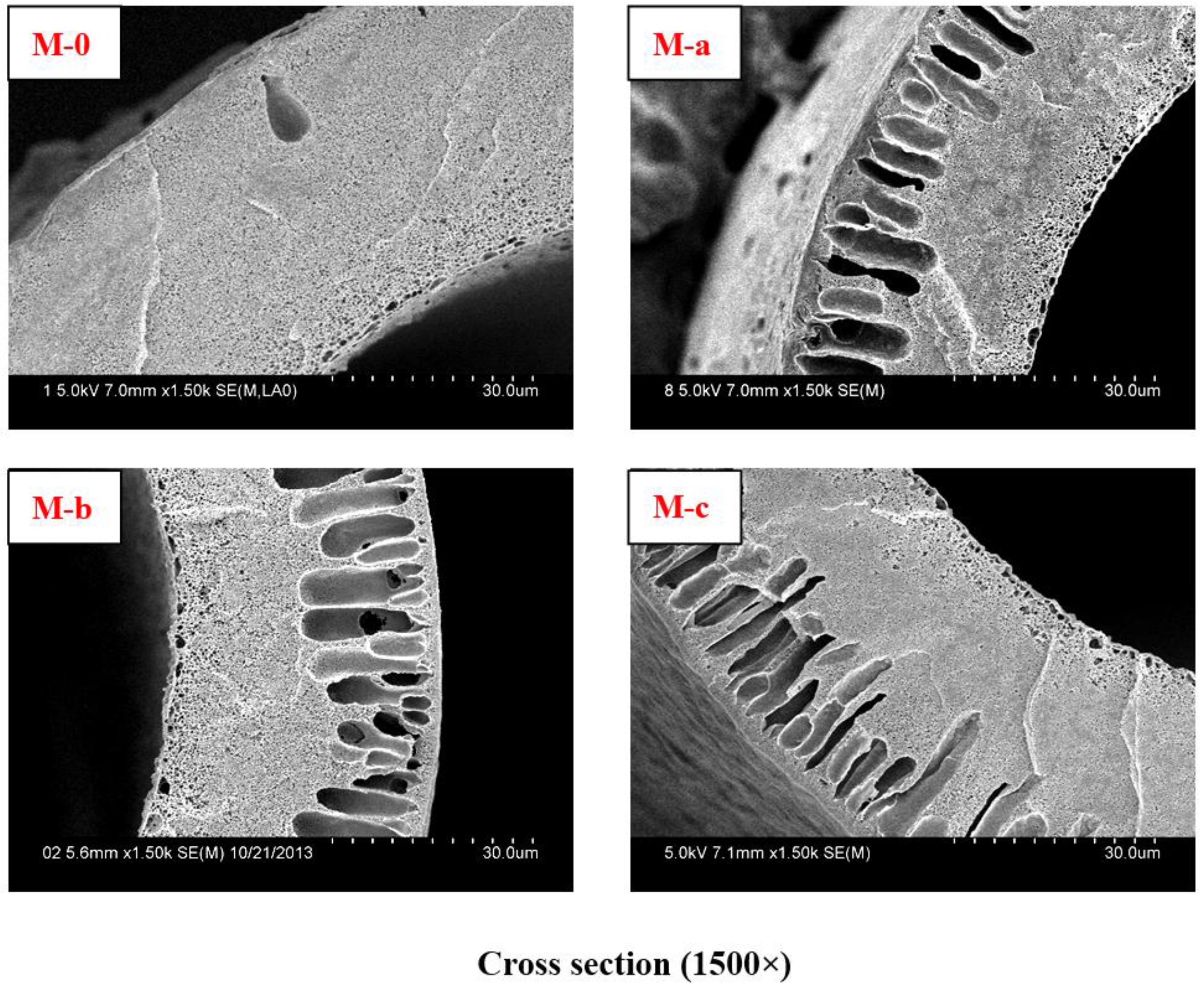
Figure 1.
Cross-sectional SEM micrographs with different PVP molecular weights in membranes. The cross-sectional SEM micrograph of Virgin PVDF membrane is M-0. The cross-sectional SEM micrographs of modified PVDF membranes are M-a, M-b, and M-c with PVP molecular weights 6 KDa, 10 KDa, and 30 KDa, respectively.
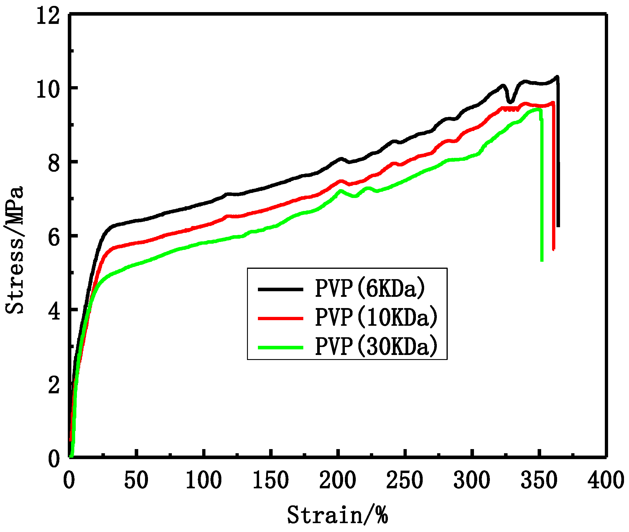
Figure 2.
The stress-strain curves of different PVP molecular weight PVDF membranes.
Figure 2.
The stress-strain curves of different PVP molecular weight PVDF membranes.
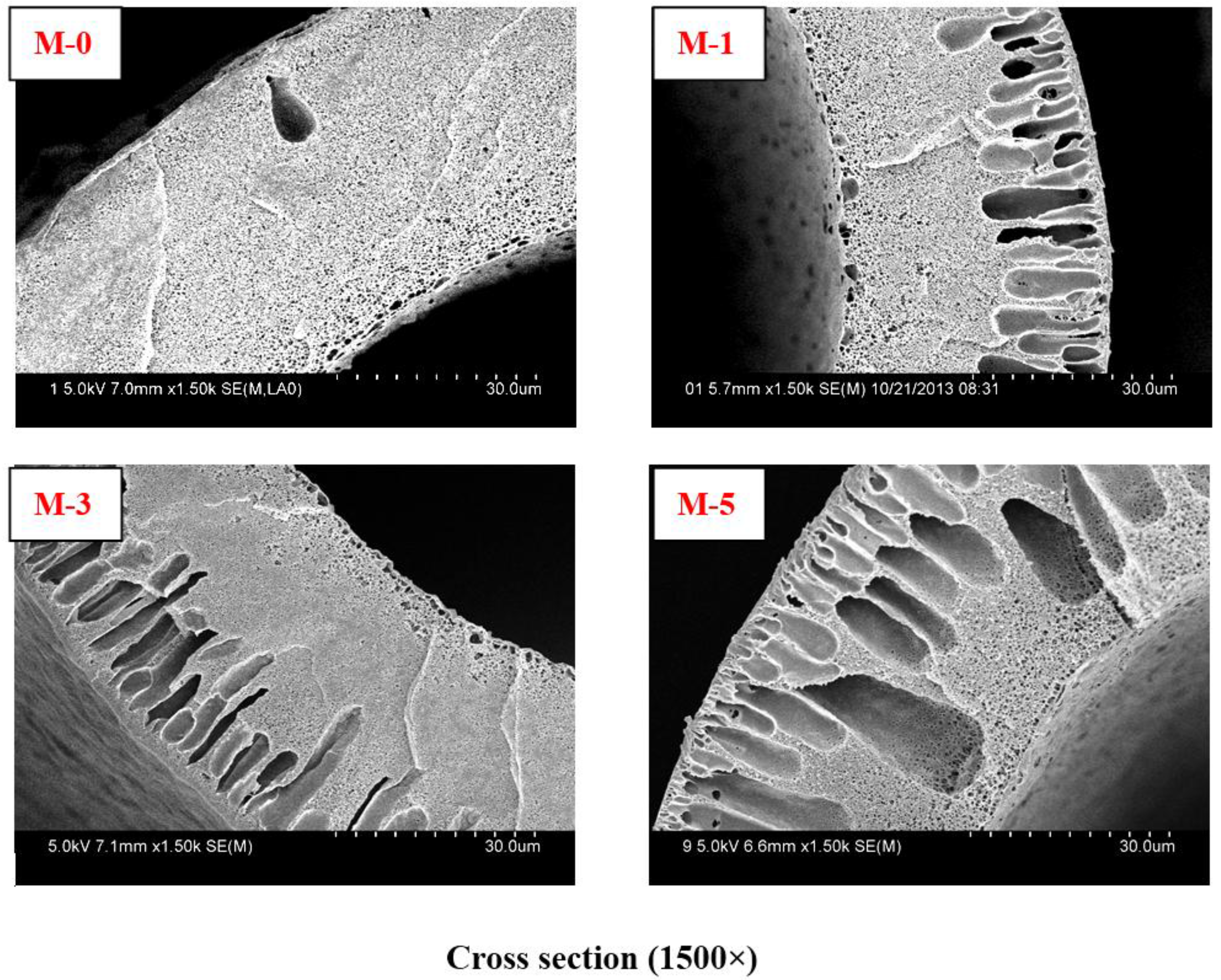
Figure 3.
Cross-sectional SEM micrographs with different PVP content in membranes. The cross-sectional SEM micrograph of virgin PVDF membrane is M-0. The cross-sectional SEM micrographs of modified PVDF membranes are M-1, M-3, and M-5 with PVP content 1.0%, 3.0%, and 5.0 wt %, respectively.
Figure 3.
Cross-sectional SEM micrographs with different PVP content in membranes. The cross-sectional SEM micrograph of virgin PVDF membrane is M-0. The cross-sectional SEM micrographs of modified PVDF membranes are M-1, M-3, and M-5 with PVP content 1.0%, 3.0%, and 5.0 wt %, respectively.
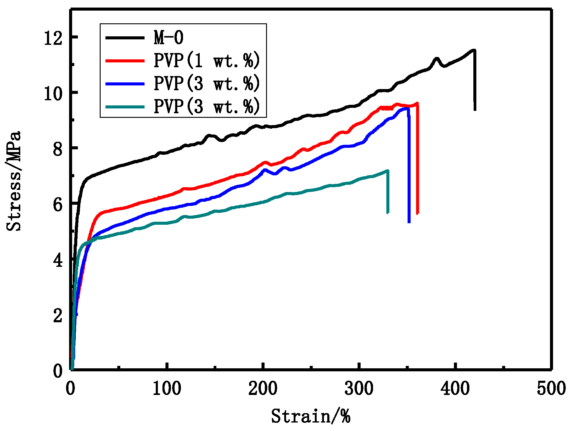
Figure 4.
The stress-strain curves of different PVP content PVDF membranes.
Figure 4.
The stress-strain curves of different PVP content PVDF membranes.
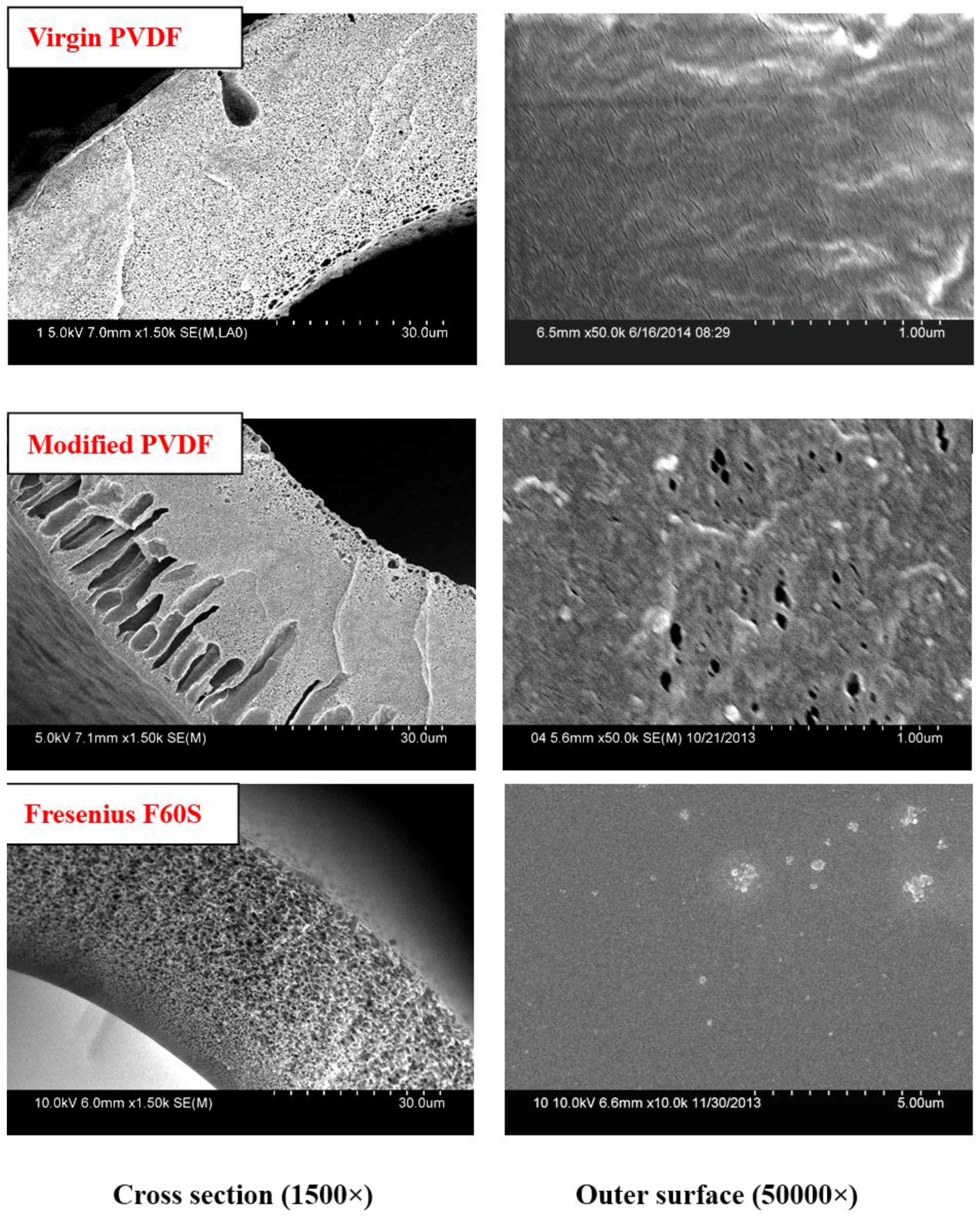
Figure 5.
Cross-sectional and outer surface SEM micrographs of PVDF and Fresenius F60S membranes. M-0 and M-3/M-c are the Virgin and modified PVDF membranes.
Figure 5.
Cross-sectional and outer surface SEM micrographs of PVDF and Fresenius F60S membranes. M-0 and M-3/M-c are the Virgin and modified PVDF membranes.
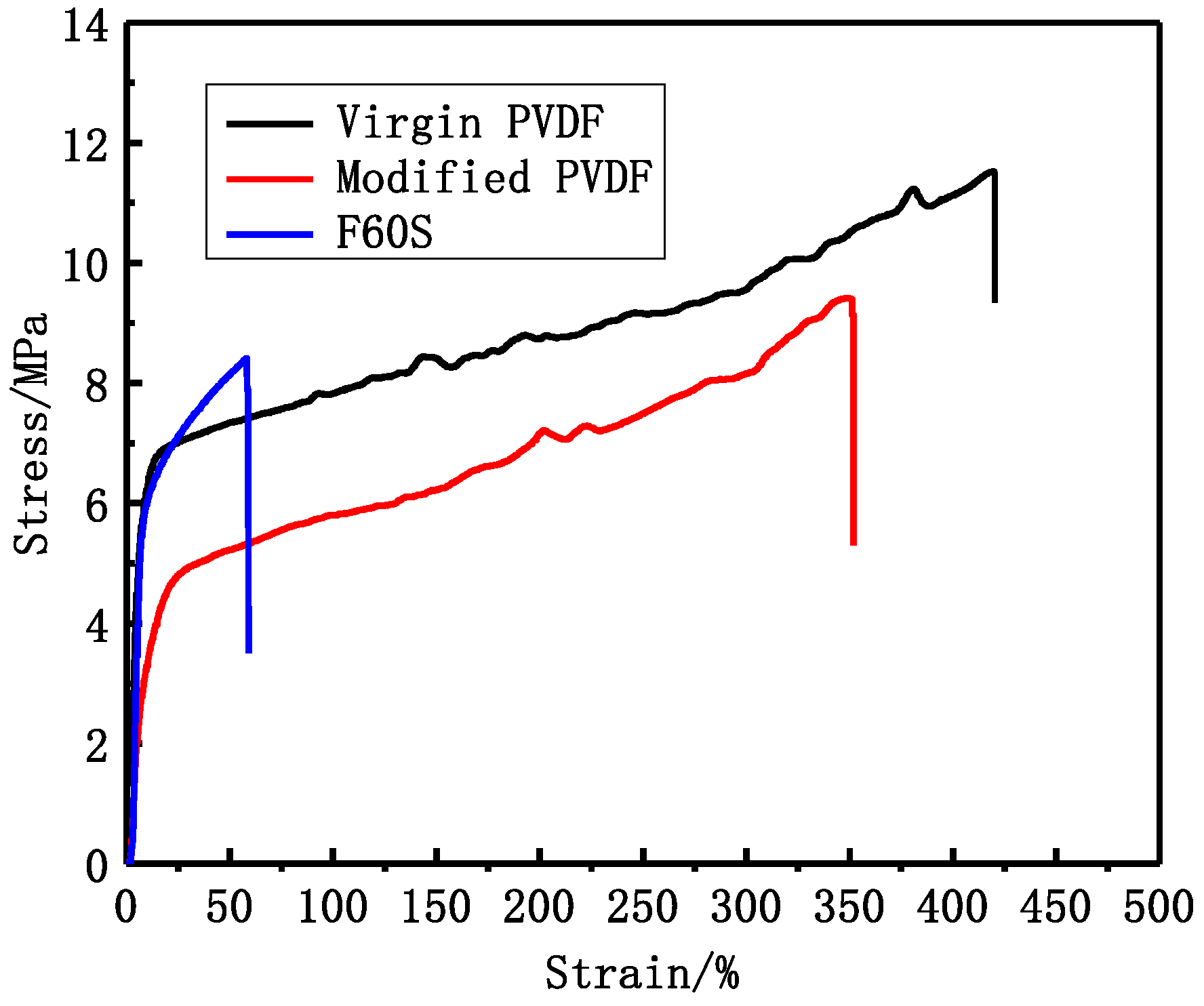
Figure 6.
The PVDF and Fresenius F60S membranes stress-strain curve.
Figure 6.
The PVDF and Fresenius F60S membranes stress-strain curve.
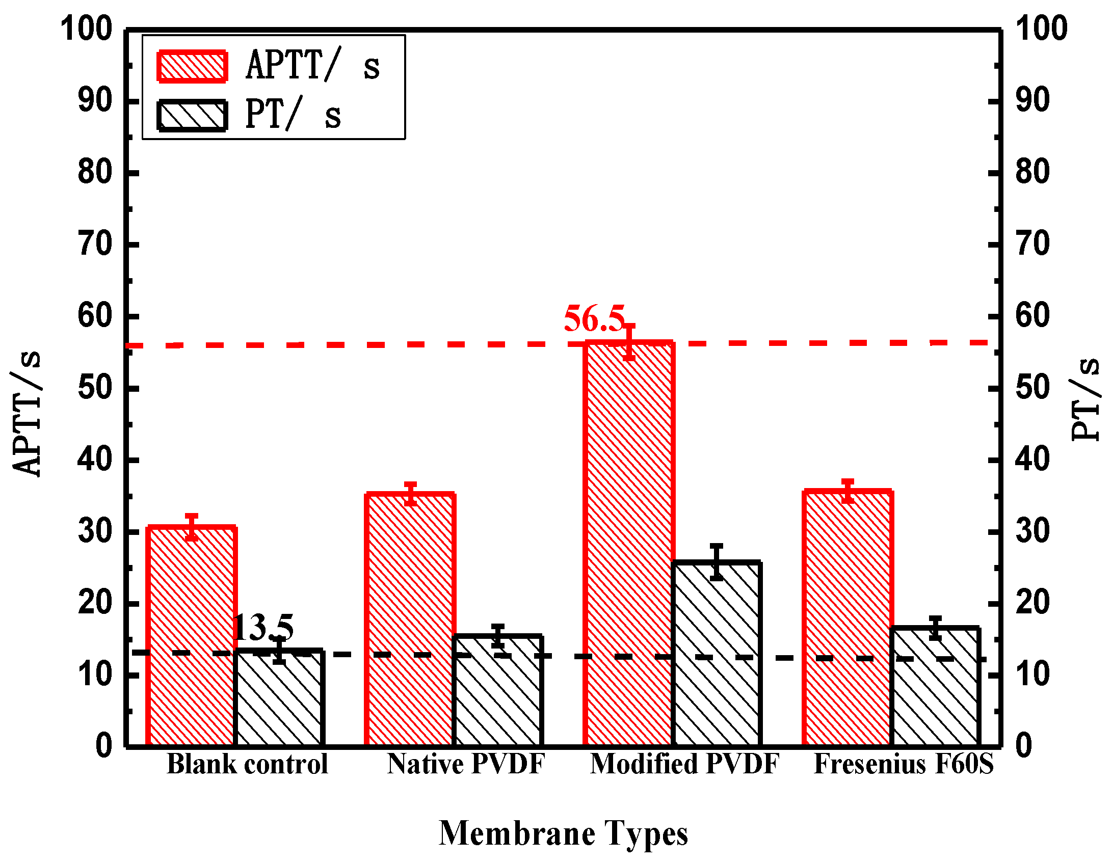
Figure 7.
The blood coagulation time of PVDF and Fresenius F60S membranes. * p < 0.05, when PVDF membranes compared with blank control.
Figure 7.
The blood coagulation time of PVDF and Fresenius F60S membranes. * p < 0.05, when PVDF membranes compared with blank control.
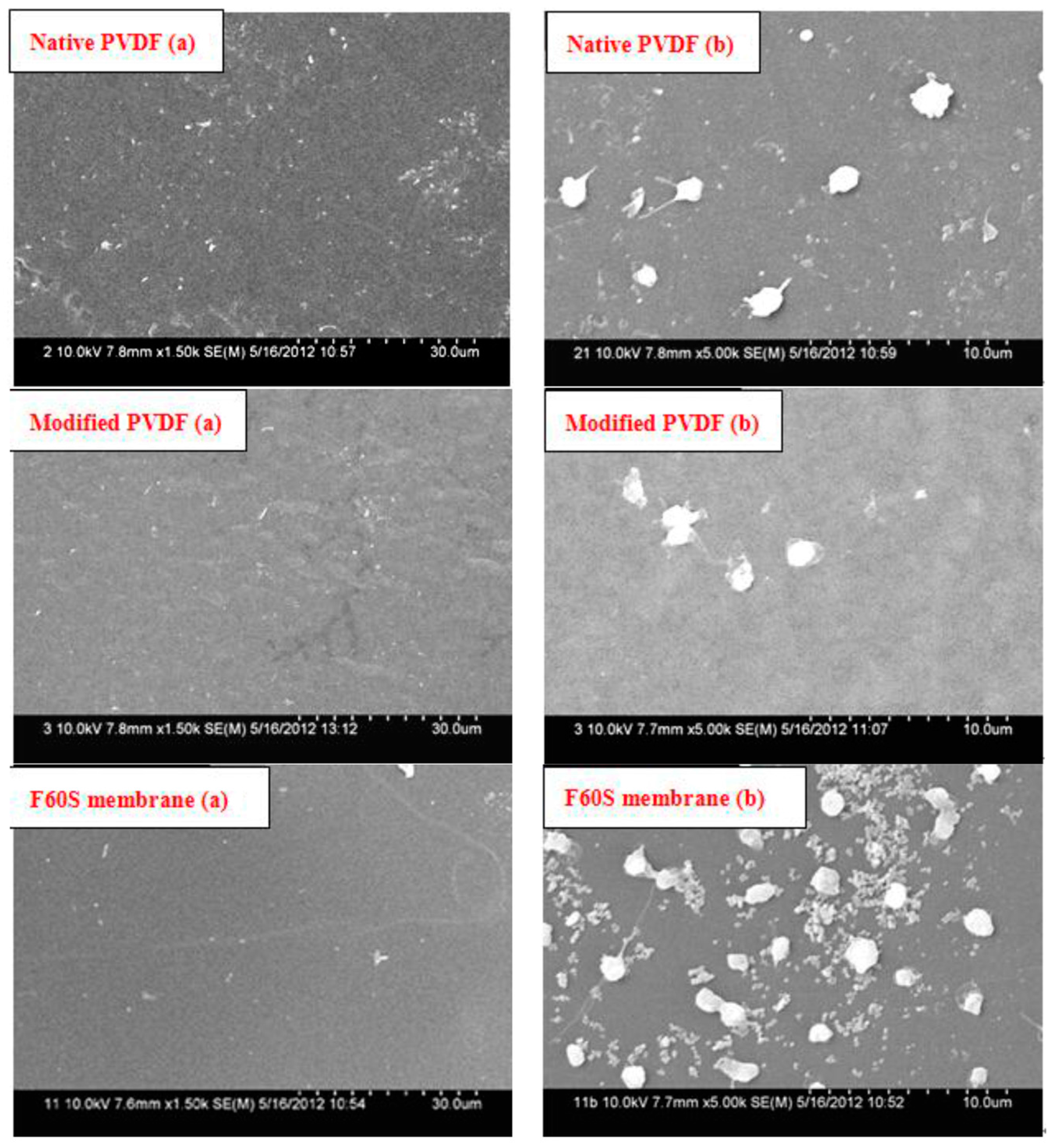
Figure 8.
Platelet adsorption of PVDF and Fresenius F60S membranes. (a) Original membrane surface feature 1500× (b) Membrane surface feature after platelet adhesion 5000×.
Figure 8.
Platelet adsorption of PVDF and Fresenius F60S membranes. (a) Original membrane surface feature 1500× (b) Membrane surface feature after platelet adhesion 5000×.
Table 1.
Spinning parameters of hollow fiber membranes.
Table 1.
Spinning parameters of hollow fiber membranes.
| Spinning Conditions | Value |
|---|
| Bore fluid | DI water (70 V %) and DMAc(30 V %) |
| External coagulant | tap water |
| Bore flow rate (mL/min) | 17.5 |
| Dope flow rate (mL/min) | 25 |
| Length of air gap (cm) | 2 |
| Take-up speed (m/min) | 56 |
| Spinneret dimension (mm) | 0.7/1.4 |
Table 2.
Effect of PVP molecular weight on some performance of modified PVDF membranes, the modified PVDF membranes are M-a, M-b, and M-c with PVP molecular weights 6 KDa, 10 KDa, and 30 KDa, respectively.
Table 2.
Effect of PVP molecular weight on some performance of modified PVDF membranes, the modified PVDF membranes are M-a, M-b, and M-c with PVP molecular weights 6 KDa, 10 KDa, and 30 KDa, respectively.
| Membrane Label | Porosity (%) | Bursting Pressure (MPa) | Max Pore Size (μm) |
|---|
| M-a | 80.8 | 0.595 | 0.069 |
| M-b | 83.3 | 0.545 | 0.072 |
| M-c | 85.7 | 0.495 | 0.073 |
Table 3.
Effect of PVP molecular weight on separation performance, the inner diameter and wall thicknesses of PVDF membranes were 200 and 40 µm, respectively. The length of membranes is about 20 cm. The surface area of membranes was 25 cm2.
Table 3.
Effect of PVP molecular weight on separation performance, the inner diameter and wall thicknesses of PVDF membranes were 200 and 40 µm, respectively. The length of membranes is about 20 cm. The surface area of membranes was 25 cm2.
| Membrane Label | UF Flux (L·h−1·m−2) | Rejection of BSA (%) | Passage of LZM (%) | Passage of Urea (%) | Contact Angle (°) |
|---|
| M-a | 483 | 93.2 | 52.5 | 93.2 | 49 ± 3 |
| M-b | 563 | 92.1 | 62.3 | 94.6 | 46 ± 2 |
| M-c | 684 | 90.8 | 72.6 | 95.4 | 38 ± 2 |
Table 4.
Effect of PVP content on some performance of modified PVDF membranes, the modified PVDF membranes are M-1, M-3, and M-5 with PVP content 1.0%, 3.0%, and 5.0 wt %, respectively.
Table 4.
Effect of PVP content on some performance of modified PVDF membranes, the modified PVDF membranes are M-1, M-3, and M-5 with PVP content 1.0%, 3.0%, and 5.0 wt %, respectively.
| Membrane Label | Porosity (%) | Bursting Pressure (MPa) | Max Pore Size (μm) |
|---|
| M-0 | 76.2 | 0.625 | 0.067 |
| M-1 | 84.1 | 0.565 | 0.071 |
| M-3 | 85.7 | 0.495 | 0.073 |
| M-5 | 90.4 | 0.370 | 0.087 |
Table 5.
Effect of PVP content on separation performance, the inner diameter, and wall thicknesses of PVDF membranes were 200 and 40 µm, respectively. The length of membranes is about 20 cm. The surface area of membranes was 25 cm2.
Table 5.
Effect of PVP content on separation performance, the inner diameter, and wall thicknesses of PVDF membranes were 200 and 40 µm, respectively. The length of membranes is about 20 cm. The surface area of membranes was 25 cm2.
| Membrane Label | UF Flux L·h−1·m−2 | Rejection of BSA (%) | Passage of LZM (%) | Passage of Urea (%) | Contact Angle (°) |
|---|
| M-0 | 313 | 91.3 | 53.2 | 94.4 | 52 ± 3 |
| M-1 | 512 | 92.4 | 58.9 | 94.2 | 42 ± 2 |
| M-3 | 684 | 90.8 | 72.6 | 95.4 | 38 ± 2 |
| M-5 | 843 | 88.2 | 82.5 | 96.7 | 35 ± 2 |
Table 6.
Some performance of PVDF and Fresenius F60S membranes, M-0, and M-c/M-3 are Virgin and modified Fresenius F60S membranes.
Table 6.
Some performance of PVDF and Fresenius F60S membranes, M-0, and M-c/M-3 are Virgin and modified Fresenius F60S membranes.
| Membrane Label | Porosity (%) | Bursting Pressure (Mpa) | Max Pore Size (μm) |
|---|
| Virgin PVDF | 76.2 | 0.625 | 0.067 |
| Modified PVDF | 85.7 | 0.495 | 0.073 |
| Fresenius F60S | 72.3 | 0.475 | 0.072 |
Table 7.
Separation performance of PVDF and Fresenius F60S membranes, the inner diameter and wall thicknesses of membranes were 200 and 40 µm, respectively. The length of membranes is about 20 cm. The surface area of membranes was 25 cm2.
Table 7.
Separation performance of PVDF and Fresenius F60S membranes, the inner diameter and wall thicknesses of membranes were 200 and 40 µm, respectively. The length of membranes is about 20 cm. The surface area of membranes was 25 cm2.
| Membrane Label | UF Flux (L·h−1·m−2) | Rejection of BSA (%) | Passage of LZM (%) | Passage of Urea (%) |
|---|
| Virgin PVDF | 313 | 91.3 | 53.2 | 94.4 |
| Modified PVDF | 684 | 90.8 | 72.6 | 95.4 |
| Fresenius F60S | 217 | 93.7 | 54.4 | 96.8 |
Table 8.
Water contact angle and BSA adsorption of PVDF and Fresenius F60S membranes, the surface area of membranes was 100 cm2.
Table 8.
Water contact angle and BSA adsorption of PVDF and Fresenius F60S membranes, the surface area of membranes was 100 cm2.
| Membrane Label | Water Contact Angle (°) | BSA Adsorption (mg/m2) |
|---|
| Virgin PVDF | 52 ± 3 | 110 ± 3 |
| Modified PVDF | 38 ± 2 | 45 ± 2 |
| Fresenius F60S | 64 ± 3 | 230 ± 4 |
Table 9.
Hemolysis ratios of PVDF and Fresenius F60S membranes. Group 1, Group 2, and Group 3 were parallel experiments of standard direct contact method.
Table 9.
Hemolysis ratios of PVDF and Fresenius F60S membranes. Group 1, Group 2, and Group 3 were parallel experiments of standard direct contact method.
| Membrane Label | Hemolysis Ratio |
|---|
| Group 1 (%) | Group 2 (%) | Group 3 (%) |
|---|
| Virgin PVDF | 0.55 ± 0.13 | 0.63 ± 0.09 | 0.69 ± 0.08 |
| Modified PVDF | 0.27 ± 0.06 | 0.31 ± 0.05 | 0.26 ± 0.04 |
| Fresenius F60S | 0.74 ± 0.21 | 0.98 ± 0.25 | 0.76 ± 0.12 |


