1. Introduction
Membrane based separation techniques are used in various industries as water and wastewater treatment [
1], gas separation, separation of chemicals and petrochemicals [
2], haemodialysis [
3] or in clinical sensors [
4], in juice production [
5], wine filtration [
6,
7,
8], separation of biomolecules [
9] or drug delivery [
10].
Isoporous membranes have been traditionally prepared via ion-track etching [
11,
12] and inorganic aluminium anodic oxidation (AAO) [
13]. While polycarbonate track-etched (PCTE) films suffer from their low pore density, AAO membranes show a high pore density with close hexagonal pore alignment in a range of 50–500 nm interpore distance that comes along with the brittle property of these films. First isoporous membranes from self-assembling block copolymers were prepared as thin layers on a solid substrate from solution and then transferred to a porous support [
14]. A well-known process to generate polymer membranes with a thin selective layer on top of a more open porous spongy substructure from the same material is the non-solvent induced phase separation (NIPS), also known as “phase inversion”. This leads to mechanically robust membranes with both good selectivity and high permeance. Applying NIPS to self-assembling block copolymers (so-called SNIPS) can lead to so called integral isoporous membranes if the right conditions are found. This was shown for the first time for block copolymers (BCPs) like polystyrene-
b-poly(4-vinylpyridine) (PS-
b-P4VP) [
15]. This leads to membranes with a highly ordered surface morphology, small pore size distribution and high porosity [
16]. Specific properties of the pore forming block itself can induce responsive behaviour towards external stimuli like changing pH or even temperature after coating with polydopamine as an interlayer which is further modified with a temperature responsive polymer such as poly(
N-isopropylacrylamide) (pNIPAM) [
17,
18]. Later on, suitable conditions for SNIPS were also found for a still increasing number of other block copolymers, namely poly(
tert-butylstyrene)-
b-poly(4-vinylpyridine) (PtBu-
b-P4VP) [
19], polystyrene-
b-poly(solketal methacrylate) (PS-
b-PSMA) [
20], polystyrene-
b-poly(ethylene oxide) (PS-
b-PEO) [
21], polystyrene-
b-poly(methyl methacrylate) (PS-
b-PMMA) [
22], polystyrene-
b-poly(2-hydroxyethyl methacrylate) (PS-
b-PHEMA) [
23] or even triblock terpolymers like polystyrene-
b-poly(2-vinylpyridine)-
b-poly(ethylene oxide) (PS-
b-P2VP-
b-PEO) [
24], polyisoprene-
b-polystyrene-
b-poly(4-vinylpyridine) (PI-
b-PS-
b-P4VP) [
25,
26] or polyisoprene-
b-polystyrene-
b-poly(
N,
N-dimethylacrylamide) (PI-
b-PS-
b-PDMA) [
27].
Besides expanding the number of block copolymer membranes obtained by SNIPS, many efforts have been made to understand the BCP membrane formation mechanism. Investigations were focused on the BCP structure formation in dependence of solvent selectivity [
28], solvent composition [
29], influence of additives helping to assemble the pore forming blocks by hydrogen bonds [
30,
31,
32] or complex formation [
33,
34], the influence of the casting conditions like solvent evaporation time [
35], temperature or humidity [
36,
37]. The tailored pore size of BCP membranes can be tuned by changing the ratio of both blocks, the total molecular weight [
38] or blending [
39]. The cast films are in a mobile, non-equilibrated state before precipitation. These wet non-equilibrated films get fixed at the moment of phase inversion, which is induced usually by the typical non-solvent water. Hexagonally or square-like packed cylinders form a 10 up to ca. 500 nm thick selective top layer [
37] and merge into a much thicker sponge-like substructure of several tens of µm, which physically supports the thin but sensitive top layer and which is in the case of flat sheet membranes usually additionally supported by an open porous non-woven substrate.
The doctor blade casting method is a well-established method for this purpose [
37]. With a gap size of usually around 150–200 µm the casting solution is flattened to a homogenous wet film. Further transportation gives the microphase separated or microphase separating BCP chains time to rearrange in the wet film and react to solvent evaporation induced gradients of concentration or temperature, before freezing the structure by a quick solvent non-solvent exchange, when it is immersed into a precipitation bath. Up to now the resulting block copolymer film thickness is limited to a minimum of ca. 11 µm using this method in our group [
40].
The reduction of the substructure layer thickness and its density is the key to keep additional pressure losses low. The high polymer consumption per unit area has up to now limited the attractiveness manufacturing BCP membranes at larger scales, as these block copolymers are expensive. Further thickness reduction by doctor blade coating technique is limited, because the coating needs a certain polymer concentration usually in the range of 15–25 wt.% to get casting solutions of sufficiently high viscosity that do not penetrate into the non-woven support material too deeply (leading eventually to pore blocking) and to keep the selective top layer without defects (i.e., no dewetting). A successful coating of ≤10 µm thin PS-
b-P4VP layer at the inner surface of a polyethersulfone hollow-fibre membrane was recently reported by our group with [
41].
Printing techniques like offset printing, pad printing, gravure printing, screen printing flexographic printing which allow a patterning of the covered surface by transferring ink onto a substrate. In contrast, coating techniques that usually involve the pouring, painting, spraying, casting or smearing of a film, such as spin coating, doctor blading, dip-coating, painting, spray coating, slot-die coating, curtain coating or slide coating generally [
42] do not offer this property. However, some of these techniques only work in a batch mode like the spin coating approach, which is prominent in the solar cell industry or DVD production and can homogenously cover 30 cm diameter samples on smooth substrates like silicon wafers. Spin coating has also been used in various studies on BCP self-assembly in thin films [
43,
44], but it cannot be transferred to a roll-to-roll (R2R) process for larger areas in contrast to e.g., profile roller coating or doctor blade casting.
R2R offers the possibility to include further production steps like heating, UV-light curing or drying, as necessary for dense membranes for e.g., gas separation [
45] or a solvent/non solvent exchange in a precipitation bath in the case of porous membranes. R2R with smooth roles of aluminium and polytetrafluorethylene was used to produce macroscopically aligned microphase separated block copolymer films from solution before [
46,
47].
To the best of our knowledge, we report for the first time the casting of highly diluted BCP solutions in large scale with a profile roller coater in a SNIPS process, leading to membranes with thin layers of PS-b-P4VP. We will present the casting method and discuss the morphological features of the block copolymer layer, such as the thickness, structural homogeneity, polymer amount per unit area, and pH-responsive water flux. Also, the suitability of different supports is investigated. Furthermore, we demonstrate that this method allows the investigation of the influence of changing evaporation time in a single sample.
2. Materials and Methods
2.1. Synthesis of PS-b-P4VP
Synthesis of the block copolymer PS-
b-P4VP was carried out via sequential living anionic polymerization following a synthesis route according to Rangou et al. [
38]. (Further information is given in the
Appendix A).
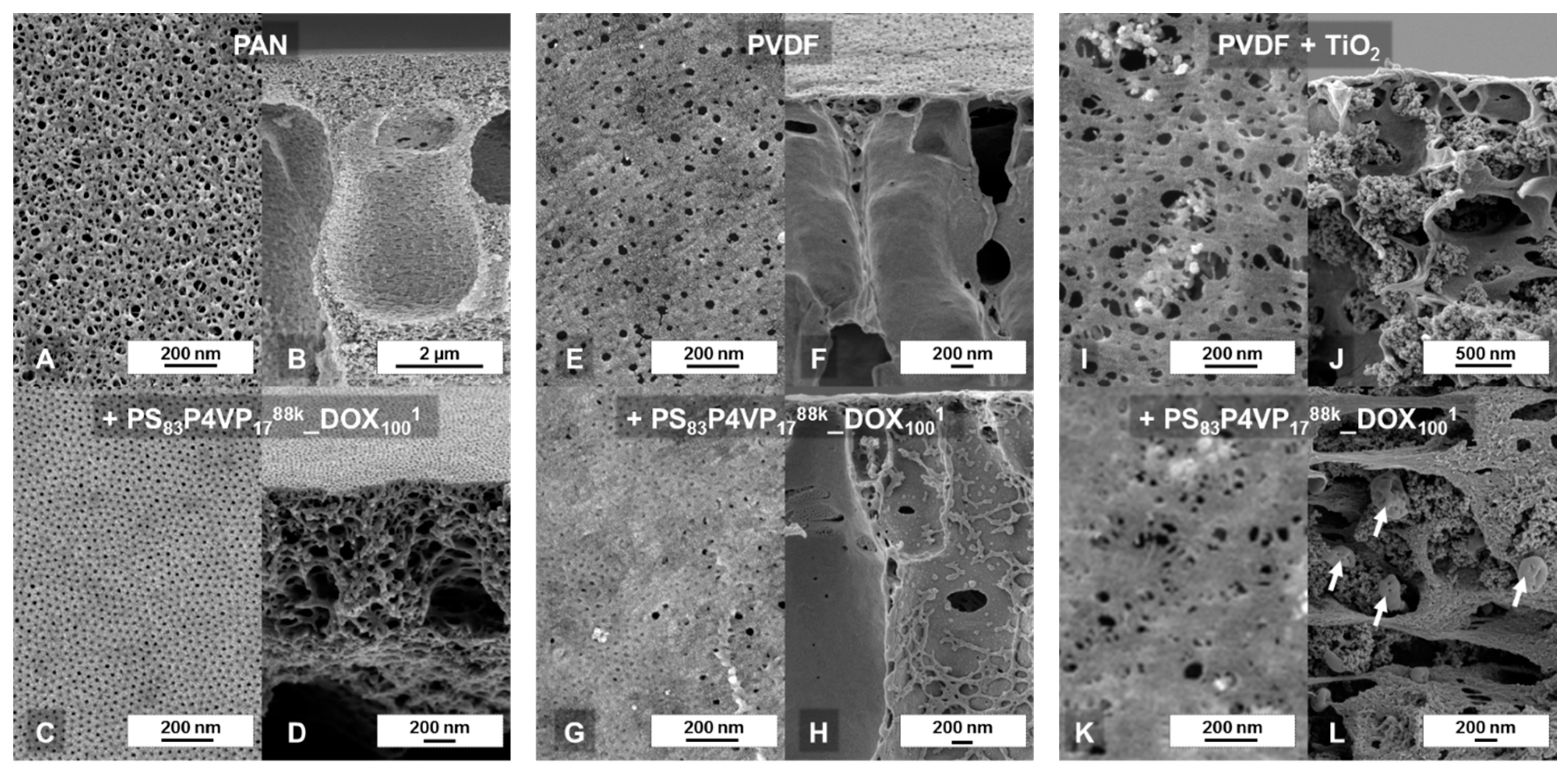
2.2. Solvents for Membrane Casting and Membrane Supports
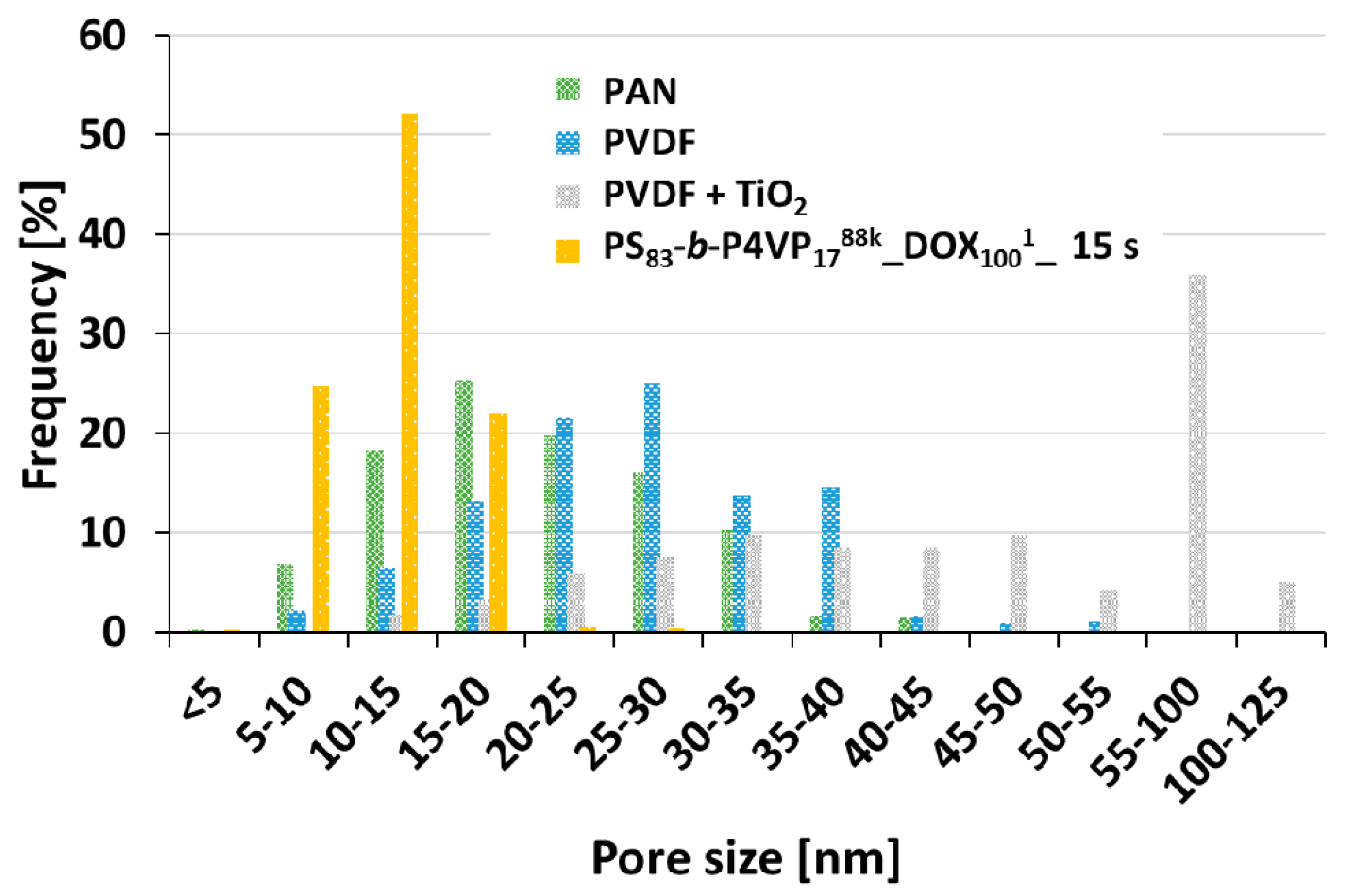
The casting solutions of low viscosity (see
Table 1) require a suitable support material that prevents excessive casting solution penetration, is resistant toward the used solvents and gives enough physical stability to the thin BCP layer. Non-woven polyester that is usually used to cast BCP membranes with a gap doctor blade [
16,
48,
49] was not suitable for this purpose, because of the too high mesh distances which prevent the formation of a film on top with the low viscous casting solutions. In this work a home-made polyacrylonitrile (PAN) support membrane was used (see
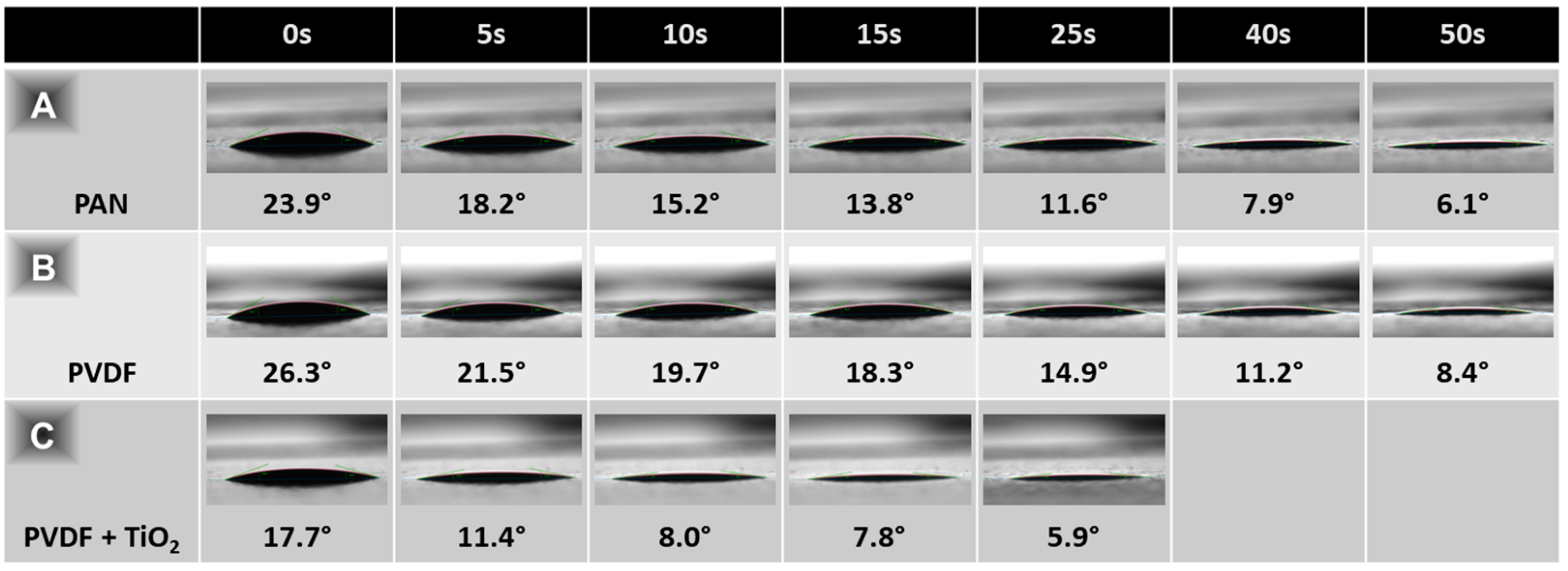
Appendix B.1). Home-made polyvinylidene fluoride (PVDF) and polyvinylidene fluoride + 8 wt.% titanium dioxide (PVDF + TiO
2 (8%)) membranes were also not suitable candidates (see
Appendix B.2 and
Appendix B.3).
2.3. Casting Solutions for Membrane Preparation
All block copolymer (BCP) casting solutions were stirred until they appeared only slightly turbid. The slight turbidity of the solutions with the selective solvent DOX is due to the formation of micelles [
28]. However, no sedimentation was observed, even after longer times. The solutions were stored overnight before further use. The polymer concentration was usually set to 1 wt.% in pure 1,4-dioxane (DOX) (see
Table 1).
An overview of all casting solutions is given in
Table 1.
Table 1 listing the used BCP, the solvent composition, its density and viscosity.
Generally, the dynamic viscosity increases with increasing molecular weight in a range from 2.318–4.253 mPa·s, also depending on the ratio of block A to block B. The density of all 1 wt.% casting solutions was in the range of the pure solvent 1,4-dioxane with 1.03 g/cm3 and independent of the polymers molecular weight or the ratio of both blocks.
2.4. Nomenclature
The block copolymers (BCP) were used in different solvent systems usually with 1 wt.% polymer concentration. The following nomenclature is employed:
where BlockA is the first block of the BCP, in this study usually polystyrene (PS), and BlockB is the second block, in this study poly(4-vinylpyridine) (P4VP). The subscripts x and y represent the weight ratio of each block in wt.%, whilst the superscript z is the total molecular weight in kg/mol. The solvent composition follows, where the subscripts m and n again describe the weight ratio in wt.% and p describes the percentage of block copolymer in wt.% within the given solvent system. In this work, mainly pure 1,4-dioxane (DOX) was used. The evaporation time before immersion into a precipitation bath can optionally form the last part of the designation.
PS-b-P4VP with a polymer ratio of 83:17 and a molecular weight of 88,000 g/mol was dissolved in a mixture of DMF and THF with a ratio 40:60 at a concentration of 1 wt.%. The membrane cast out of this solution had an evaporation time of 15 s.
2.5. Viscosity and Density Measurements
The densities and viscosities of the used polymer solutions were measured with a DMA 4100 M (Anton Paar, Graz, Austria) density meter. The measurements were carried out with a 1.59 mm 1.4125-steel ball of 7.66 g/cm3 density in a 1.59 mm glass capillary at 20 °C.
2.6. Roller Coating
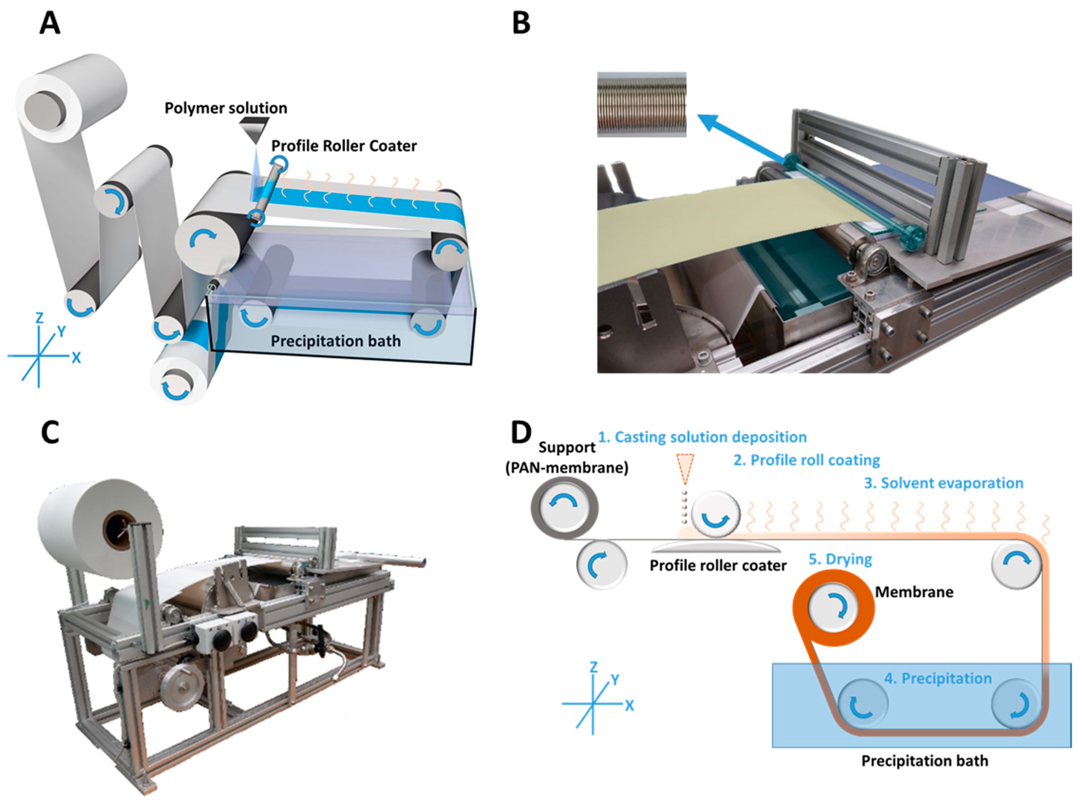
The casting process itself was carried out with a profile doctor blade (Zehntner GmbH, Sissach, Switzerland) of 0.32 m application breadth, 1.5 cm in diameter and with a weight of 359 g. It was mounted into two smooth-running ball bearings, 35 g each, which makes it a profile roller coater. The profile pattern was formed as described in the following section.
U-shaped milled rings into a rod are radially and periodically arranged, with a distance of 0.550 mm (
Figure 1B; top-left) leading to a theoretical wet film thickness of 50 µm after the wave crests and troughs have converged to a uniform film.
The casting of the profile roller coated PS-
b-P4VP membranes (
Figure 1A) was carried out by continuous deposition of the casting solution (1) onto a moving PAN support membrane in front of the profile roller coater; the solution was immediately flattened to a homogenous wet film (2); the following solvent evaporation step gave the microphase separating system time to self-assemble (3) before immersion into a precipitation bath for quick solvent/non-solvent exchange, which froze the structure (4); in a last step, the resulting membrane was dried (5) (
Figure 1D).
Further details:
A smooth glass plate below the support was employed to induce counter pressure. In order to compensate small thickness variations of the PAN support membrane, the ball bearings were movable in Z-axis (
Figure 1). Hence the roller coater could move up or down with changing support thickness. The contact pressure was given by the operating weight of the profile coater and its two bearings with a mass of 429 g.
The volumetric flow rate of the low viscous casting solution was continuously adjusted to the consumption of the casting process itself, in order to prevent strong leakage at the edges or a lack of solution before the roller coater. A 5 mL syringe was used manually for this purpose, but this can easily be carried out with a volumetric flow pump or a spraying nozzle as well.
2.7. Film Thickness Gauge
For film thickness measurements of BCP-films cast on a PAN membrane, a magnetic inductive measurement device (ISO2178) DeltaScope® FMP10 (Fischer GmbH, Sindelfingen, Germany) was used. Then, 100 data points were taken randomly on different positions of the sample.
2.8. Gravimetrical Polymer Consumption Measurements
The polymer consumption per unit area was determined (a) by measuring the required quantity of casting solution per unit gravimetrically with a Quintix 224-1S laboratory balance (Sartorius AG, Göttingen, Germany) and additionally (b) by the mass difference before and after coating with a XP105 analytical balance (Mettler Toledo, Greifensee, Switzerland). The Software ImageJ 1.51w (by Wayne Rasband) was used to determine the coated surface area by image analysis. All samples were dried under reduced pressure at 60 °C for at least 24 h before further investigations.
2.9. Photo Imaging under UV Light and Daylight Condition
An 8°W UV-lamp (Camag, Berlin, Germany) was used at a wavelength of 254 nm for imaging under UV light conditions. An EOS D60 camera (Canon, Krefeld, Germany) was used for imaging in manual mode with the settings f-number F5.6, ISO1000 and shutter speed 5 s, in dark room conditions.
2.10. Scanning Electron Microscopy (SEM)
A Merlin scanning electron microscope (Carl ZEISS, Oberkochen, Germany) was used for imaging of membrane samples at voltages between 3 kV up to 50 kV. The samples were sputter coated with 2.0 nm of a platinum layer to avoid charging. Cross-sections were prepared by dipping the membranes into iso-propanol, freezing in liquid nitrogen and subsequent cracking. The average pore size distribution and the average porosity were determined by analysing SEM-images using the software IMS (Imagic Bildverarbeitung AG, Glattbrugg, Switzerland).
2.11. Water Permeance Measurements
Pure water permeance measurements were carried out in dead-end mode using an in-house-device. The effective membrane area was 1.77 cm
2. The transmembrane pressure (TMP) was detected by two LEO3 pressure gauges (Keller AG, Winterthur, Switzerland). Measurements were carried out at room temperature and at 1 bar TMP. The mass of the permeate was measured gravimetrically every minute. The first 15 min of measurement were excluded from calculations to give the membrane flux time to stabilise. We used demineralised pure water provided by a LaboStar
TM UV2 (Siemens; Berlin, Germany) with an electrical conductivity of ≈0.055 μS·cm
−1. The permeance (
L) is calculated by normalizing the flux to the TMP.
ΔV is the volume of collected water and t the time between two measurement points; A is the membrane’s top surface area and p is the transmembrane pressure.
2.12. pH-Responsive Measurements
Solutions of 1 L pure water and 0.5 g sodium chloride (Merck kGaA; Darmstadt, Germany) were adjusted with hydrochloric acid (Sigma Aldrich, St. Louis, MO, USA) and sodium hydroxide (Sigma Aldrich) to pH = 3 and pH = 5, respectively, to test the pH responsive behaviour of the samples with regard to their permeance in a 200 mL Millipore testing cell (Merck kGaA; Darmstadt, Germany). The sample surface area was 1.77 cm². Starting with the solution with pH = 5 at 2 bar TMP, the first 15 min from permeance calculations were excluded to give the membrane time to equilibrate and then the mass change over the following 5 min was measured gravimetrically. The solution was then exchanged, the bottle was washed twice with the exchange solution (pH = 3) and this alternating procedure was carried out four times.
2.13. Retention Measurements
Solutions of 0.02 wt.% poly(ethylene glycol) (PEG) in H2O were used to perform retention measurements. The Mws of the used PEGs were 53, 106, 187 and 220 kDa. First, the pure water permeance was measured for 3 h at 2 bar TMP in a Millipore cell (Merck kGaA, Darmstadt, Germany), followed by substitution of the water with 100 mL PEG-solution. After 5 min stirring without applied pressure, a feed sample was taken. Subsequently, 30 mL of permeate were collected at 2 bar TMP and discarded in order to ensure equilibration and another 4 mL were collected afterwards as permeate sample.
The calculation of retention
R is carried out using the following equation:
The feed concentration cf and the permeate concentration cp of the samples were determined by gel permeation chromatography (GPC) at 35 °C in bidistilled water with 0.5 g/L sodium azide using PSS acrylate copolymer SUPREMA Pre, 100 Å and 3000 Å columns (particle size 10 µm), at a flow rate of 0.5 mL·min−1 (VWR—Hitachi 2130 pump). A Waters 410 index detector with a PEG calibration was used.
3. Results and Discussion
With the aim to reduce the consumption of block copolymer per unit area, in this work highly diluted casting solutions were used in contrast to conventional gap doctor blade cast membranes. The coating technique was successfully changed to a profile roller coating approach (see
Section 2.6), which allowed for an additional reduction of the wet film thickness (WFT). The combination of both lead to thin porous PS-
b-P4VP layers in the range of 0.5–3 µm after precipitation and drying, on top of a PAN support membrane. The savings of BCP per unit area easily exceed 95%. Additionally, a method to quickly investigate the influence of a changing evaporation time for the membranes using one sample only is presented. The support properties and the film homogeneity will also be discussed. Furthermore, the retention and pore size distribution of a PS
83-
b-P4VP
17_DOX
1001 membrane and the PAN support will be considered.
3.1. Mass Per Unit Area
The great potential of the roller coating method becomes apparent at a closer examination of the polymer consumption per unit area in g/cm
2. For a first theoretical approximation, the covered surface area of a roller coated sample was determined as 766 cm
2. A wet film thickness of 50 µm was assumed based on manufacturer information. This data allows for the determination of the theoretical polymer consumption when the concentration of the casting solution is known, which was 1 wt.% in this case. The exact wet film thickness is not measurable due to the porous substrate, which immediately soaks in part of the solvent. However, the gravimetric mass change of a sample membrane with respect to its pristine support and the additional simple measurement of the required quantity of casting solution will allow for a more realistic comparison to a gap doctor blade cast membrane from 15.5 wt.% of PS
76-
b-P4VP
24330k in a mixture of DMF/THF (40/60). The results are shown in
Table 2.
The polymer consumption of theoretically 0.5 g/m2 per unit area of the roller coated PS83-b-P4VP17_DOX1001 is only 1.7% in comparison to the theoretical value of 31 g/m2 of a doctor blade cast PS76-b-P4VP24330k_DMF40THF6015.5 on a polyester non-woven with a gap size of 200 µm. A membrane with a relatively low concentration of 15.5 wt.% was chosen for comparison reasons. In practice, the consumption was even lower with 0.3%, namely 0.26 g/m2 for the roller coated instead of 81 g/m2 for the doctor blade cast membrane. The reason is the partial penetration into the non-woven support, which additionally increases the thickness of its wet film. The gravimetrically measured amount of the roller coated (RC) membrane is approximately half of its theoretical value, which is explainable because the 50 µm film thickness is a calculated value by the manufacturer, without considering rheological influences. In roller coating mode of operation not the whole casting solution is transferred to the support and parts remain within the profile. That is why the resulting film is thinner than a theoretical wet film of ~50 µm.
Because of the small gravimetric mass change of only 0.02002 g (±0.15 mg) for our ~766 cm2 (i.e., 0.26 g/m2) cast sample, the required quantity was also determined by examining the mass change of the casting solution over the production period which was 2.3065 g in total and hence 0.3 g/m2. The two values are in good agreement. The very small deviation between required quantity and gravimetric mass change also shows that losses due to the casting process are negligible. Small amounts remain on the roller coater itself or are applied to the edges of the membrane where the film gets thinner, i.e., a section that is not used as part of the homogeneous membrane and which was excluded from surface area calculations.
The applied mass of 2.3065 g also shows that the wet film must be thinner than the approximately 50 µm quoted by the manufacturer, since using this wet film thickness only an area of 444 cm2 instead of 766 cm2 would have been coated.
3.2. Coating and Film Homogeneity
The described coating technique (see
Section 2.6) represents a straightforward way of coating thin BCP membranes in a SNIPS and R2R process. The setup could be improved, e.g., by replacing the glass plate with a counter roll equalising the applied force, by using a metric pump for controlled application of the casting solution or by transferring the casting solution indirectly from a reservoir with one or more rolls to the support (see
Figure 1). However, even without these improvements it was possible to successfully coat thin BCP membranes over a large scale. The used PAN support showed a good wettability with the casting solution (additional information is given in
Appendix G).
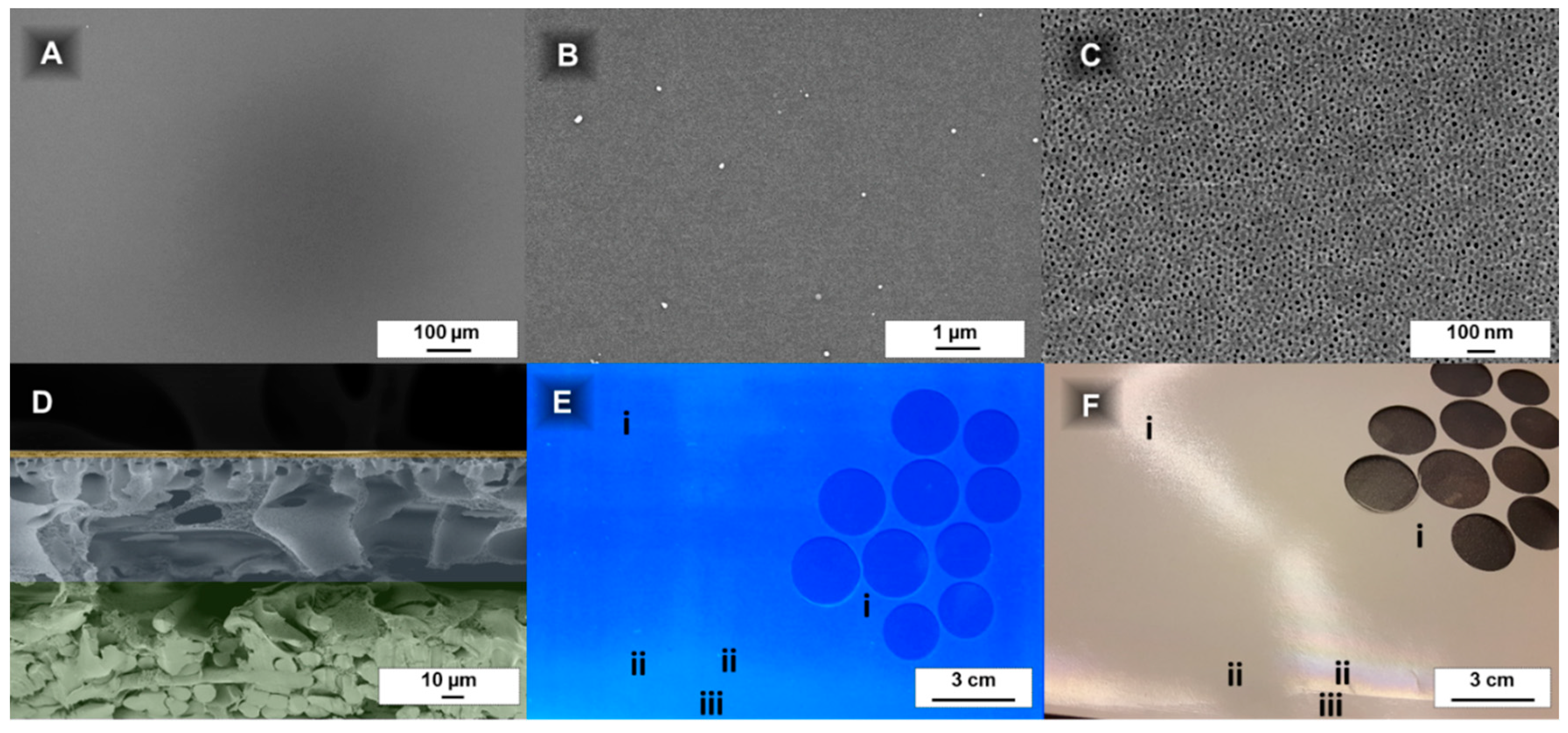
Because the film thickness is reduced to below 3 µm with this coating technique (
Figure 2D and Figure 6;
Appendix D), the film homogeneity evaluation becomes more difficult. SEM investigations were conducted to prove that the coating is uniform on a microscopic scale. Additional imaging under daylight and under UV-light conditions allows to evaluate the homogeneity on a larger scale.
3.2.1. Investigation of Film Homogeneity by Daylight
For macroscopical homogeneity observation, an easy method to find deviations in the layer thickness is holding the sample against a light source and observe the reflection (
Figure 2F). Areas with a changing colour indicate the PS-
b-P4VP coating becoming very thin (e.g., close to the membrane edges).
This may sound trivial, but the porous support, its waviness and the thin PS-
b-P4VP prevent simple and time efficient film thickness measurements (e.g., with a film thickness gauge device) (additional information is given in
Appendix F). The determination of the thickness of a PS
83-
b-P4VP
1788k_DOX
1001 membrane with 15 s evaporation time cast on a PAN support membrane was attempted with a magnetic inductive film thickness gauge. A value of 168.8 µm (SD 9.43) was determined for the homogenous middle part of the membrane (
Figure 2F-i). At the edge of the film (
Figure 2F-ii) a value of 169.0 µm (SD 7.56) was measured and the pristine, uncoated PAN part (
Figure 2F-iii) of the membrane had a thickness of 176.5 µm (SD 6.96). This comparison shows the deviations are too big to credibly calculate the PS-
b-P4VP layer thickness by subtracting the PAN membrane thickness. Generally, the PS-
b-P4VP or PtBS-
b-P4VP layers appear smoother with a tendency to better reflect light in contrast to the PAN support (
Figure 2F). However, it is difficult to draw a conclusion from a single image since changing light-reflections make the documentation difficult (see
Figure 2F at position ii within and without of the light reflection). For this reason, a UV-light-method was employed to supplement the measurement technique described above.
3.2.2. Investigation of Film Homogeneity by UV-Light
PAN showed fluorescence under UV-light with a wavelength of 254 nm [
50], while the PS-
b-P4VP layers remain black. With this method, a way to identify deviations in the PS-
b-P4VP layer thickness was found. They appear as darker (for thicker layers) or brighter areas on a UV-light image. The shutter speed of the camera was increased to 5 s to get sufficient contrast for this purpose.
The films appeared homogenous over the whole casting area, except the 2–3 cm at the edges, like seen under day-light conditions (see
Section 3.2.1;
Figure 2F), where the PS-
b-P4VP films become brighter and more and more closely resemble the uncoated purple colour of the pristine PAN, which is an indication for a thinner film. This method allows to straightforwardly evaluate the film quality in a qualitative way over a larger scale for fluorescing support materials.
3.2.3. Investigation of Film Homogeneity by SEM
The top layer SEM images confirm a homogenous coating at a microscopic scale of up to 1 mm (
Figure 2A–C) and the cross-sectional images reveal that there is nearly no deviation in layer thickness. Also microphase separation (
Figure 2C) appears to be uniform over a large range.
3.3. Influence of the Evaporation Time on Membrane Morphology
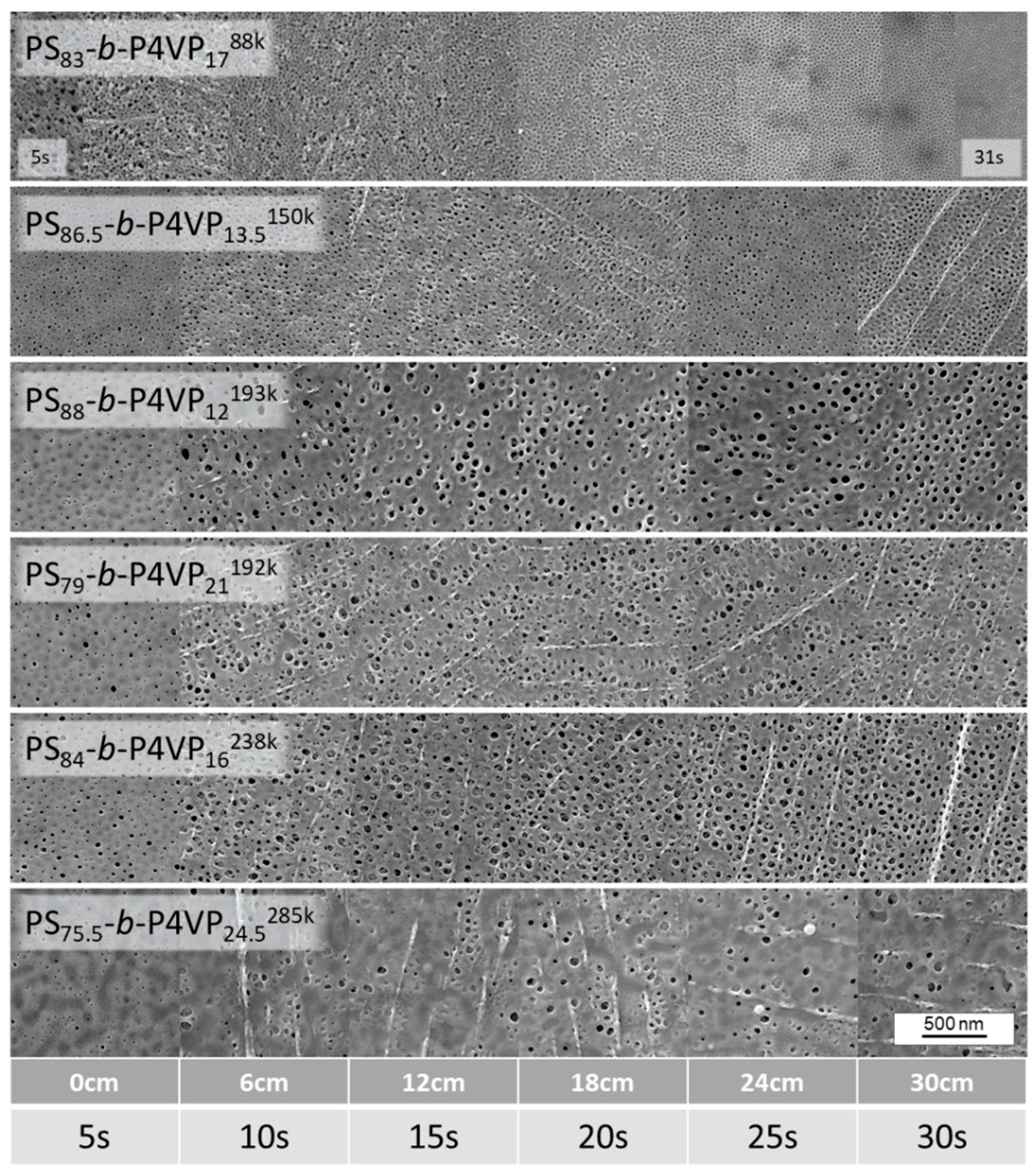
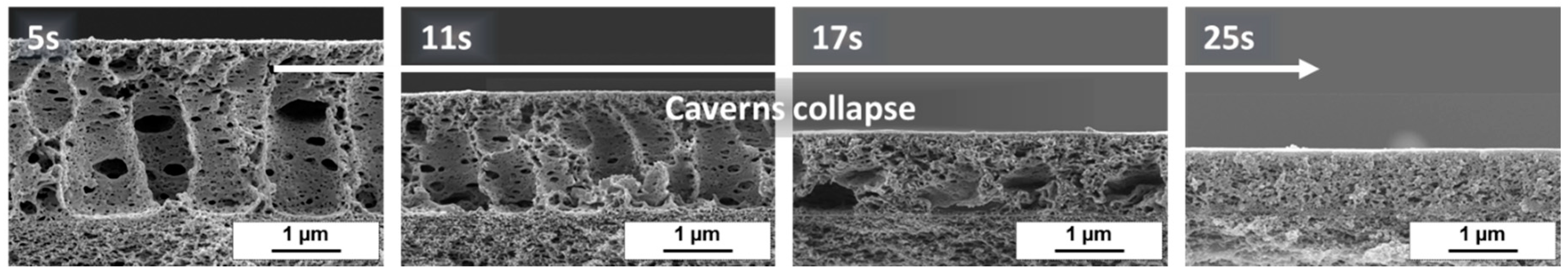
The precipitation bath freezes the membrane in a non-equilibrated state. The continuous solvent evaporation induces gradients of polymer concentration, viscosity and temperature within the wet polymer film. The resulting membrane morphology is therefore strongly determined by the evaporation time prior to immersion of the film into the precipitation bath. In the following section a method is described that allows the facile investigation of the pore development with ongoing evaporation time using one sample only, instead of casting many single samples.
As shown in
Figure 3, such gradient sample membranes were cast with a speed of 8.2 cm/s and when they reached the precipitation bath after traveling 41 cm (i.e., 5 s of evaporation time), the velocity was decreased to 1.2 cm/s. This results in the evaporation times of the sample to continuously increase along the sample, in this case up to up to 30 s.
This method excludes deviations due to changing testing conditions (e.g., different room temperature, air humidity or air flow of the fume hood or changing concentration of the casting solution) which might affect experiments with individually produced samples.
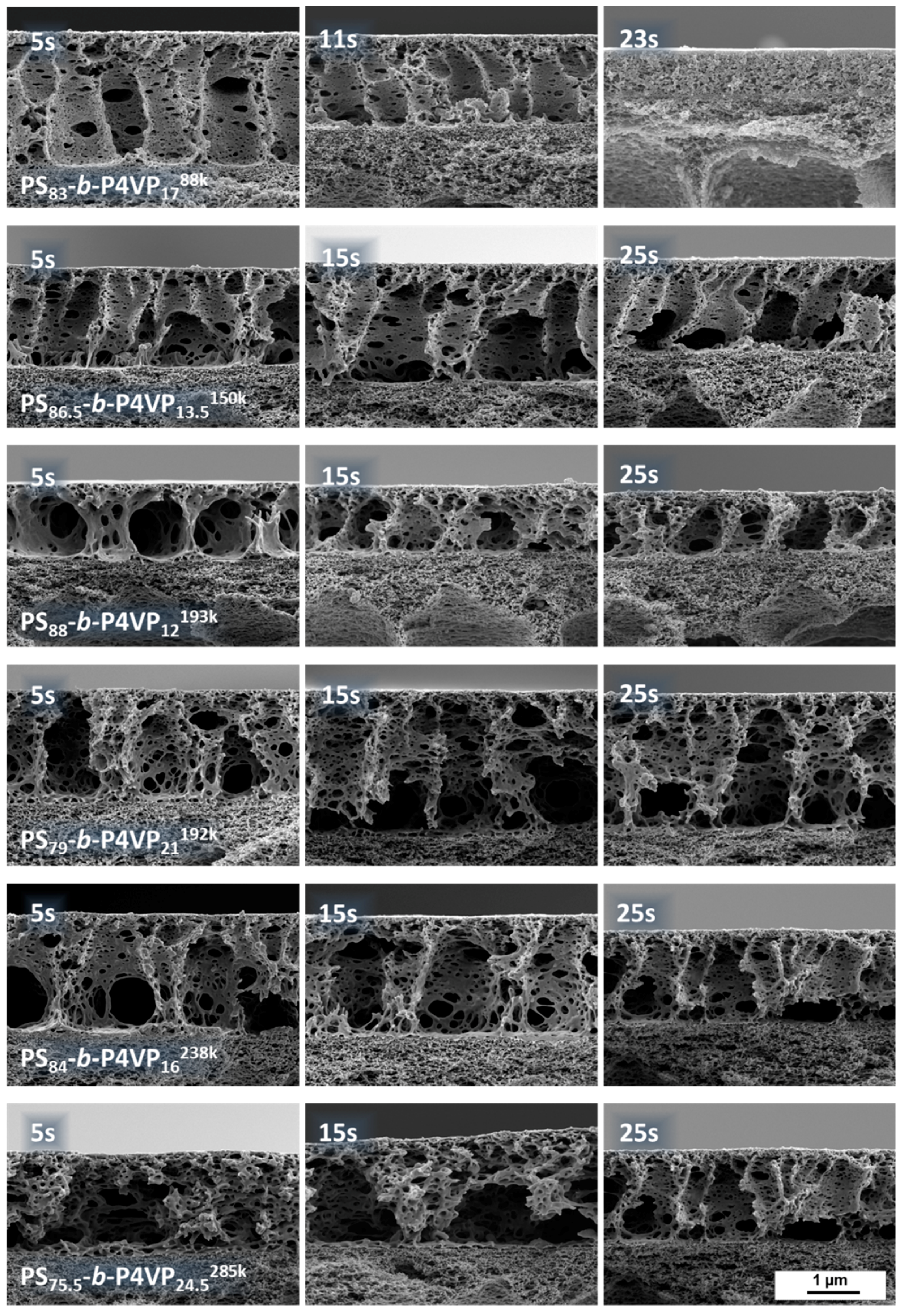
Evaporation time gradient samples were prepared from all casting solutions listed in
Table 1. As an example, the gradient sample of PS
83-
b-P4VP
1788k_DOX
1001 which shows an irregular structure after a short evaporation time of 5 s is presented. With increasing evaporation time, the pore structure becomes more regularly arranged with an optimum between 15–23 s. Afterwards the pores start collapsing again and become increasingly dense (
Figure 4). According to SEM images, the average pore size after 15 s evaporation time for a PS
83-
b-P4VP
1788k_DOX
1001 was 12.5 nm (SD 3.3) (see
Appendix C).
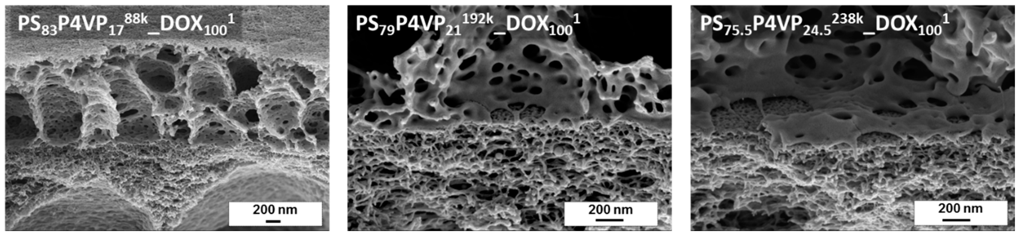
The tilted cross-sectional SEM images of PS-
b-P4VP_DOX
1001 membranes give information about the interface between the PS-
b-P4VP-layer and the PAN support membrane. As can be seen, the BCP is not penetrating the PAN support. The PS-
b-P4VP chains remained above the PAN layer, forming a highly open layer with large caverns (
Figure 5).
The cross-sectional view also reveals the cavern development with ongoing evaporation time (
Figure 6). Whilst the spongy substructure is highly open with extremely large caverns after 5 s and a layer thickness approximately of 2.6 µm, it constantly shrinks with ongoing evaporation time with 1.8 µm, 1.2 µm and 0.9 µm after 11 s, 17 s and 23 s, respectively. The development of the membrane morphology nicely shows the dynamics of the system and the importance of freezing of the structure at the right moment.
The higher molecular weight PS-
b-P4VP block copolymers also showed similar thin layer thicknesses. However, their pore morphology requires further improvement by tuning of the solvent composition. SEM cross sectional images are available in the
Appendix D.
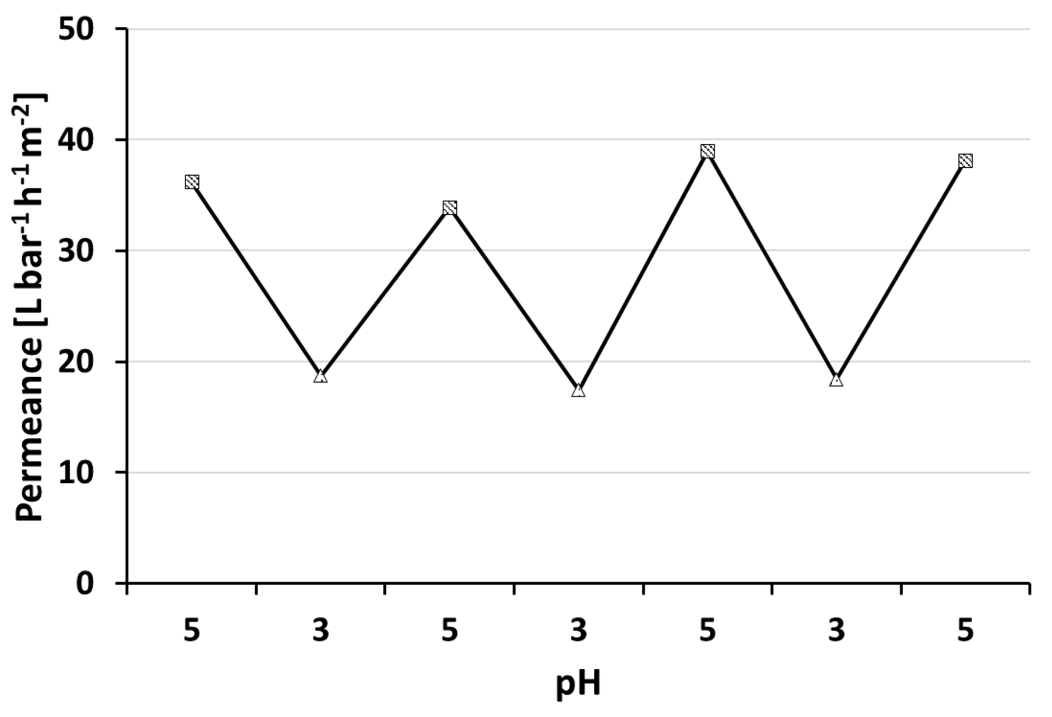
3.4. pH-Responsive Measurement
PS-
b-P4VP membranes show the ability to respond to changing pH values of the feed solution (
Figure 7). Lowering the pH value leads to protonation of the nitrogen’s free electron pair of the pore forming P4VP block. The repulsion of the positive charges in turn leads to a swelling of the polymer chains and to an effective pore size reduction in consequence. Hence a permeance decline is observed at lower pH-values. Changing the pH value between pH = 5 and pH = 3 confirmed that the pH-responsive, switchable nature for thin layered, profile roller coated PS-
b-P4VP membranes is preserved. This process could be reproduced several times. Similar observations were made by our group with spray cast membranes prepared using the same polymer solutions but a PVDF support membrane [
40]. However, generally higher water permeances of 400 L·bar
−1·h
−1·m
−2 at pH = 5.1 were observed. The PVDF support was tested for roller coating application, but it was found to be not suitable in this case due to strong penetration that lead to defects (see
Appendix B.2).
For both preparation methods, the supporting membrane was partly blocked by penetration of the BCP casting solution. We assume this blocked area might be higher in our case on a PAN support compared to the air brush spray cast samples on PVDF. However, this approach is designed for a scalable R2R-process, while the airbrush approach leads to circular samples of approximately 3 cm diameter and is probably difficult to upscale.
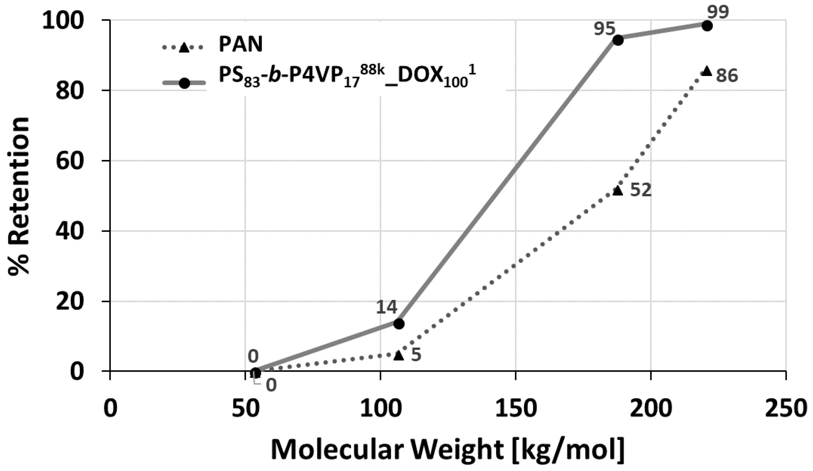
3.5. Retention
The retention was determined with solutions of PEGs with molecular weights between 53 up to 220 kDa. The retention increased from 5% up to 95% between 106 kDa PEG and 187 kDa PEG, whilst the PAN membrane only showed 52% retention for 187 kDa PEG. Hence, the molecular weight cut-off (MWCO) >90% can be assumed in the range of 106–187 kDa (
Figure 8).
The relatively sharp cut-off curve of the PS
83-
b-P4VP
1788k_DOX
1001 membrane is a result of its isoporous nature with a narrow pore size distribution observed on the SEM image (
Figure 2C and
Figure 4). At lower pH = 3, the retention of the PEG-106 kDa increased from 14% to 65% and for the PEG-55 kDa from 0% to 35%. This is a result of the pore shrinking of PS-
b-P4VP membranes in acidic milieu as shown by pH-responsive water permeance measurements before (see
Section 3.5).
3.6. Mechanical Properties
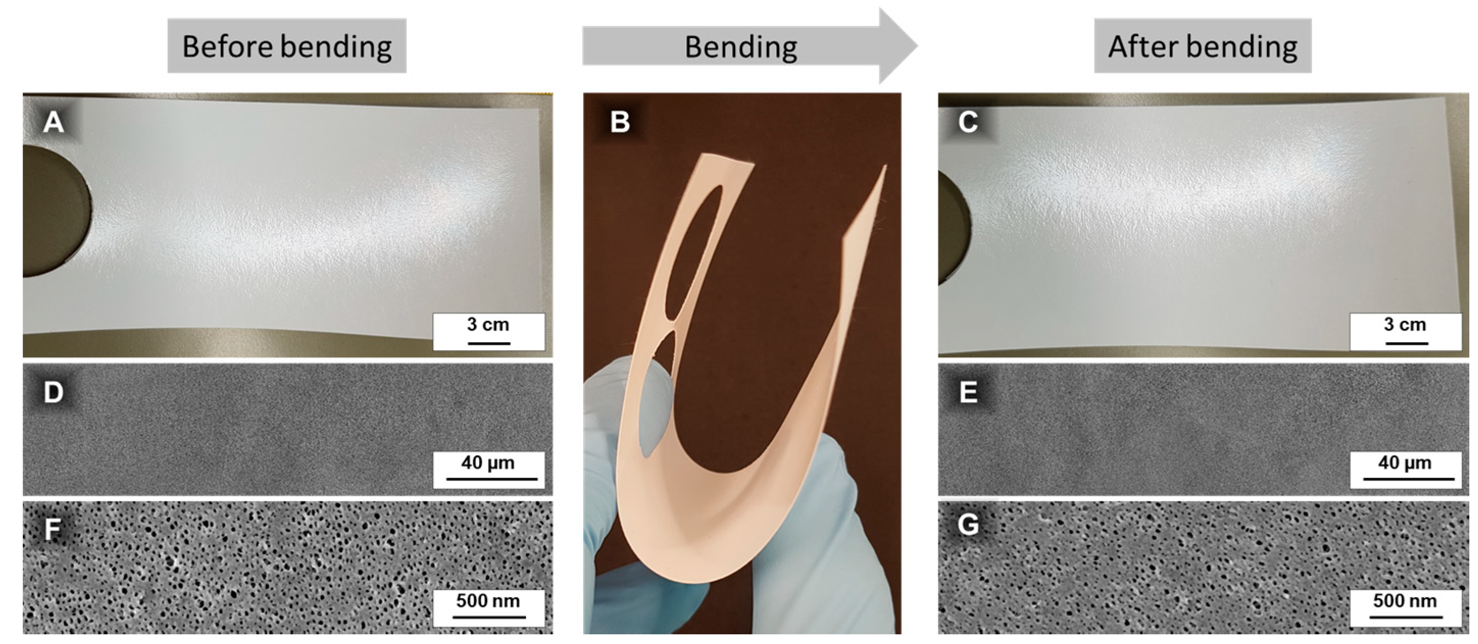
As it is difficult to determine mechanical properties of the thin coated membrane by simple methods such as tensile testing, the surface morphology of the membrane was investigated before and after bending and remained unaffected (
Appendix E). Additionally, its stability was demonstrated by a stable pure water permeance, when changing the transmembrane pressure between 1 and 5 bar (
Appendix E).


