Mechatronic Solutions for the Safety of Workers Involved in the Use of Manure Spreader


1
Department of Agricultural and Forestry Sciences (DAFNE), University of Tuscia, Via S. Camillo De Lellis, 01100 Viterb, Italy
2
National Institute for Insurance against Accidents at Work (INAIL), Via di Fontana Candida, 1, 00078 Monte Porzio Catone, Italy
*
Author to whom correspondence should be addressed.
Agriculture 2017, 7(11), 95; https://doi.org/10.3390/agriculture7110095
Submission received: 25 September 2017
/
Revised: 19 October 2017
/
Accepted: 30 October 2017
/
Published: 6 November 2017
(This article belongs to the Special Issue Smart machines, Remote Sensing, Precision Farming, Processes, Mechatronic, Materials and Policies for Safety and Health Aspects)
Abstract
:An internationally acknowledged requirement is to analyze and provide technical solutions for prevention and safety during the use and maintenance of manure spreader wagons. Injuries statistics data and specific studies show that particular constructive criticalities have been identified on these machines, which are the cause of serious and often fatal accidents. These accidents particularly occur during the washing and maintenance phases—especially when such practices are carried out inside the hopper when the rotating parts of the machine are in action. The current technical standards and the various safety requirements under consideration have not always been effective for protecting workers. To this end, the use of SWOT analysis (Strengths, Weaknesses, Opportunities, and Threats) allowed us to highlight critical and positive aspects of the different solutions studied for reducing the risk due to contact with the rotating parts. The selected and tested solution consists of a decoupling system automatically activated when the wheels of the wagon are not moving. Such a solution prevents the contact with the moving rotating parts of the machine when the worker is inside the hopper. This mechatronic solution allowed us to obtain a prototype that has led to the resolution of the issues related to the use of the wagon itself: in fact, the system guarantees the stopping of manure spreading organs in about 12 s from the moment of the wheels stopping.
1. Introduction
The risk of injuries related to the use of agricultural machinery has always been of primary importance, as evidenced by the high incidence of work-related accidents resulting from the improper use of agricultural machinery and equipment [1,2,3].
The aim of this work focuses on the needs—recognized at national and European levels—to provide technical solutions against the risk of crushing, catching, and cutting during the use of self-propelled or towed manure spreaders [4,5,6]. These are agricultural machines used to distribute manure or other materials over a field [7]. Their use is fairly widespread in livestock farms, but it could be even more widespread in the future because climate change may require more organic matter inputs to the soil over vast areas of the globe [8,9].
Sector-specific studies and surveys [6,10,11] have identified particular constructive critical issues on some machines currently in the market and/or already in use that involve the above-mentioned risks and determine the occurrence of a significant number of serious or fatal accidents. In particular, the access of an individual into the loading hopper when the rotating parts of the machine are in motion is not prevented.
Although specific safety procedures such as lockout or energy dissipation are required by occupational health and safety (OHS) regulation in many countries [12], the workers often work in hazardous conditions because in this way they are facilitated in cleaning operations. With the rotating parts in motion, the debris are removed more easily compared with the operation carried out only with the aid of water jets. In this operating mode, workers show greater attention to reducing working times and fatigue rather than increasing safety levels, thus demonstrating a risk underestimation [13]. Another reason for safety procedures not always being observed is that agricultural machinery are often owned and operated by families and not companies; thus, the OHS regulations are rarely observed.
The technical standards in force concerning this type of machine or the risks arising from its use [14] have not always been effective for the protection of workers. A critical point which is often observed regards the washing and maintenance operations carried out by operators located inside the hopper when the rotating parts of the machine are in motion. Similar problems also occur in other machines, such as forest chippers [15].
In European and international literature, statistical data regarding accidents during the use and maintenance of this type of machine are available [16,17,18,19,20,21,22]. In France, between years 2002 and 2012, eight injuries during the use of manure spreaders were recorded by IRSTEA (Institut National de Recherche en Sciences et Technologies pour l’Environnement et l’Agriculture) [20], three of which were fatal; the common cause of these accidents is the trapping of the operator between the spreading organs. Moreover, these accidents occurred during three different stages of work: cleaning, maintenance, and unlocking the rotor. In Germany, between 1998 and 2008, 12 fatal accidents were recorded by LSV-SpV (Spitzenverband der landwirtschaftlichen Sozialversicherung) [16] during the use of this machine. The common cause for eight of these accidents was the same: catching of operator between the spreading organs. These accidents occurred during various machining steps: three during cleaning, two during maintenance, two during unlock, and one during a non-defined working phase. There were a total of 17 accidents occurring in Italy during the use or maintenance of such equipment which were recorded by INAIL (Istituto Nazionale per l’Assicurazione contro gli Infortuni sul Lavoro) [17,19], all occurring between 2002 and 2015: nine fatal accidents were caused by the overturning of the tractor to which the manure spreader was attached, due to the excessive slopes of the ground (so cannot be counted among those the manure spreaders are responsible for); two cases with the same dynamics and tragic outcome, but involving self-propelled spreaders; two cases (of which one was fatal) occurred during the replacement and maintenance of the trailer wheels; two fatal cases were due to the crushing caused by the not-inserted handbrake; two cases (of which one was fatal) occurred during rotor maintenance. Other data are available outside Europe: in Ontario (Canada), six fatal accidents due to manure spreaders were recorded by CAIR (Canadian Agricultural Injury Reporting) between 1990 and 2008 [18]; in California (USA), the OSHA (Occupational Safety and Health Administration) recorded one fatal accident in 2015, during a cleaning operation [22].
Since 2009, the Health and Safety Office of the French Ministry of Agriculture and Food started various feasibility studies with regard to the improvement of the safety of manure spreaders during the washing operations, with the aim of a revision of the harmonized Standard EN 690 + A1 (Safety of Manure Spreader) [14]. The results of these studies confirm both the possibility of cleaning the moving parts of the machine (e.g., rollers and conveyor belt) without the need for the operator to be inside the load compartment while carrying out this operation, and the possibility of providing the machine of a system that prevents the movement of rotating parts when the machine itself is not in motion (steady wheels), thereby eliminating the risk of trapping the operator inside the rotating parts [6,10,11]. Moreover, the development of a safety indicator during machine design, and an associated algorithm for the assessment and optimization of productivity, could improve the safety of the machine itself [23,24,25].
2. Materials and Methods
With the aim of selecting the best solution in terms of risk reduction, SWOT analysis (Strengths, Weaknesses, Opportunities and Threats analysis) was applied to different solutions proposed by different authors [6,10,11]. The choice of this method is due to the fact that the authors of the different analyzed solutions have already carried out a risk assessment in accordance with ISO 12100 [26]: SWOT analysis also considers external parameters such as economics and feasibility of the proposed solutions.
The SWOT analysis is a support analysis that responds to a need for rationalization of decision-making processes [27]. In practice, this type of study is a logical process, originally used in business economics and then applied to other areas [28,29,30], which makes it possible to make systematic and useful information collected about a specific theme. The amount of data collected with this system is crucial to outline the policies and lines of action that result from enhancing strengths and reducing weaknesses in light of the opportunities and risks that normally arise from the external situation.
The advantages of this analysis are: depth analysis of the context in the definition of strategies; verification of matching between strategy and needs effective improvements; it allows for consensus on the strategies (if all parties involved in the intervention participate in the analysis); and flexibility.
The disadvantages of this analysis are: the risk of subjective procedures by the evaluation team in the selection of the actions; it can describe reality in a way which is too simplistic; if there is no implementation in the context of partnership, there is a risk of discrepancy between a pragmatic scientific and political plan [31,32,33].
3. Results
The mechatronic solution resulted in a system that minimizes the risks for the operator’s safety. From a mechatronic point of view, the decoupler consists of a magneto-mechanical mechanism [34] that prevents motion to all moving parts of the wagon if the machine is not in motion. The reset of the movement is possible via a hold-to-run control applied in a secure area of the wagon itself.
The basic elements of the system are:
- wagon wheel movement detectors (wheels);
- a motor disengagement device (clutch);
- a torque limiter to limit the torque during overloads;
- a programmable logic controller (PLC);
- a man-made command for manual resetting of conveyor and distributor systems, located in a safe area;
- a hydraulic distributor or a solenoid valve for conveyor control.
Considering the existing electromagnetic clutches on the market, there is little availability of clutches suitable for electric voltages that correspond to those of the tractor (12 V), and above all suitable to withstand the dissipation of rotations with the torque values of the machines rating. The minimum data for the correct sizing of the clutches are very variable. The only information currently available are shown in Table 1.
The variability of the characteristics of the wagons on the market is very wide; other variables are to be considered that would not allow a fair uniformity of adoption. Possible variables are due to:
- transmission shaft type below the loading platform;
- geometric shape;
- length;
- diameter;
- mass of the entire axis;
- any vibrations and/or movements.
Since transmission shafts are very similar to the cardan shafts commonly used on agricultural vehicles, we have come to the following conclusions.
The SWOT analysis conducted (Table 2) shows how the application of the decoupler is a mechatronic solution applicable on a great scale which ensures an optimal result to remedy the safety problems related to this machine. A similar solution has recently been applied to other machines [15].
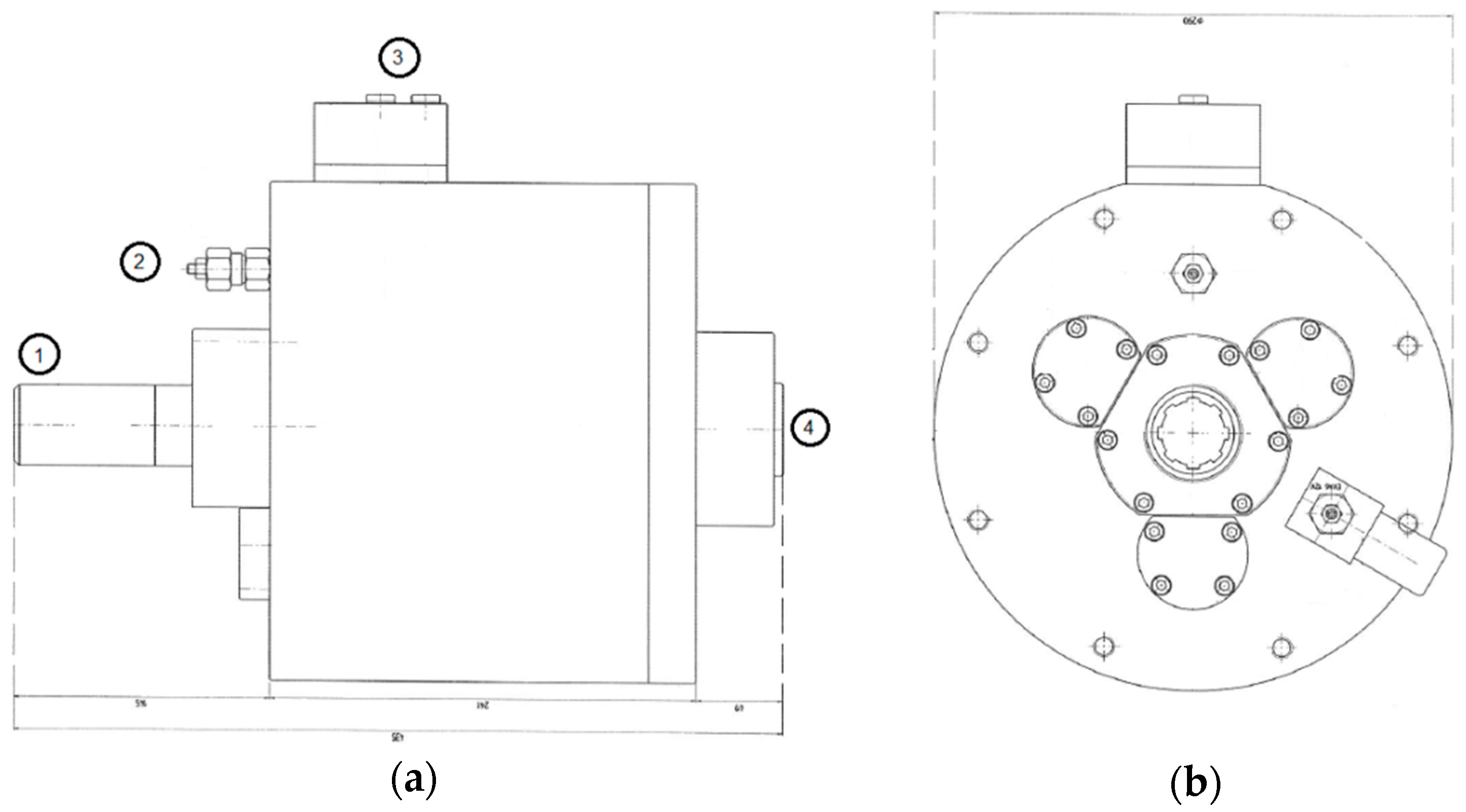
A decoupling system (Figure 1 and Figure 2) has been designed and developed thanks to the cooperation of the company Ren Mark Snc (San Polo d’Enza, Italy). A prototype of the system was applied to a towed model of manure spreader (Ren Mark RP140).
A system diagram is shown in Figure 3.
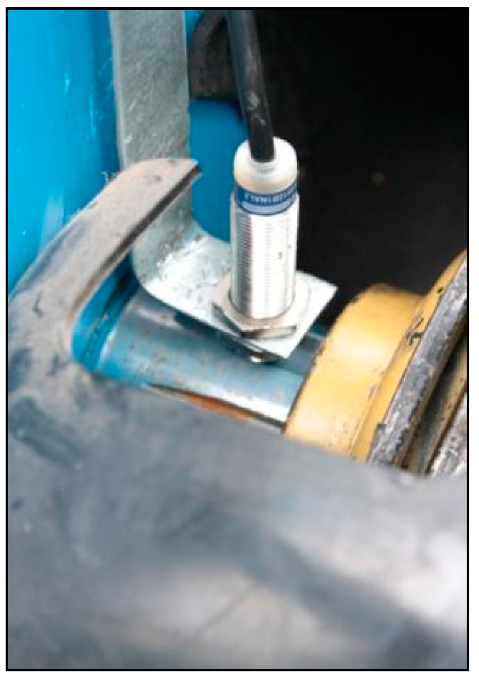
Wheel motion detection is achieved by means of a magnetic proximity sensor that detects the passage of the metal surface of the nuts mounted on the wheel drum (Figure 4), which, passing through a distance of 1 to 2 mm, make that sensor generate an electrical pulse that is detected by the microprocessor (Figure 5). Five dices are mounted on the wheel to detect even low rotation speeds.
When the sensor no longer detects the metal surface on the drum for a time less than or equal to 6 seconds, the system activates the blinking and deactivates the output to release the movement of the mechanical organs by stopping its movement as a function of the motion detection by the sensor mounted on the tractor PTO (Figure 6). Consequently, the microprocessor determines the disengagement of the multidisc clutch as a result of the internal pressure loss of the decoupler generated by the electric pump and thus allows decoupling transmission to the manure spreader that stops while the tractor PTO continues to be active.
In order to prevent the motion transmission in case of failure in connecting to the 12 V power supply, the used clutch is of the “normally open” type.
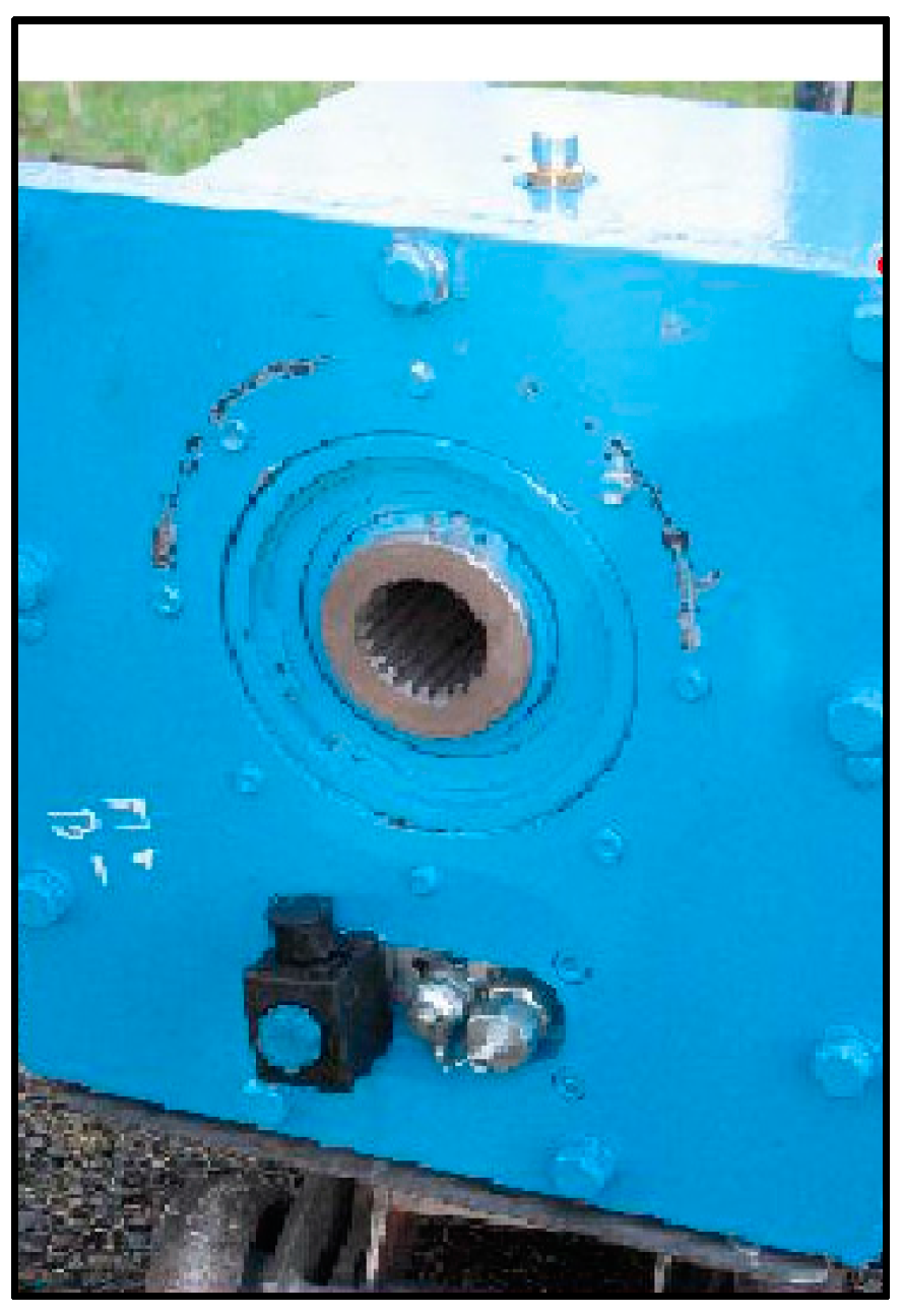
In this way, the manure spreading organs, located behind the chassis on which the decoupling device is mounted, are no longer connected to the power take-off and rotate to neutral until they are stopped in a short time.
A series of field trials showed an average time of stop of the rotors equal to 12 s (Table 3). The 12-s time can be set when programming the PLC: in particular, the decoupler will operate 6 s after the wheels are stopped and the other 6 seconds are due to the inertia of the rotors.
A video showing the operation of the device is available at the link [35].
As soon as the manure spreader connected to the tractor runs again, the sensors—specifically the ones on the wheel’s drum—resume signaling, thus resulting in the rearm of the multidisc clutch, and the resumption of rotating parts’ motion.
As said before, the system is also equipped with a hold-to-run control which allows to engage or disengage the clutch when the operator has the need to intervene at a standstill. The command must be positioned at a safe distance from the working organs and in a position which allows good visibility of the danger zones.
The technical characteristics of the prototype device installed on the wagon used for the tests are given in Table 4.
Applicability
The prototype decoupler can be applied to various models of manure spreader: the only technical trick that needs to be adopted is to change the internal solenoid valve pressure. The tested prototype—built according to the power absorbed by the machine (60 kW)—had an operating pressure of 15 bar.
Depending on the absorbed power, the pressure must be adjusted according to the following values:
- absorbed power 60 kW → operating pressure 15 bar;
- absorbed power 74 kW → operating pressure 20 bar;
- absorbed power 88 kW → operating pressure 30 bar.
4. Discussion
The tested mechatronic system would be the most effective and safe in terms of the safety of the operator working inside the hopper of the wagon. In fact, the basic concept of “firm wheels–static working organs” would prevent—or would definitely decrease—any type of risk of contact with rotating parts.
Nevertheless, as mentioned above, the implementation issues are many. The considerable additional cost that this device would entail for the manufacturers of such machines should also be considered, which would in some cases raise the sales prices (and hence the purchasing cost for consumers) with a possible drop in sales.
In addition, given the complexity of designing and implementing the system, it is likely that there will be a wide dissent from manufacturers, which would probably be opposed to the proposal for adapting the technical standard relating to the safety of manure spreader wagons.
However, this technical solution gives the opportunity—depending on the dimensional types of wagons and therefore of the decoupling system—to adapt and improve the safety of the machinery fleet present throughout the European territory.
To date, the field-tested decoupler is the best solution to overcome the major problems that arise when using the manure spreader wagon. The 12 s from the wheel stopping are sufficient to ensure that it is impossible to enter the hopper when the rotors are still in motion.
In this way, specific activities of the workers that were previously made in the absence of safety conditions (and in a way that does not comply with current health and safety regulations) could be carried out in complete safety.
Finally, the reliability of the solution will need to be addressed. Standards such as ISO 13849 [36,37] and IEC 62061 [38] describe the design of safety control systems. The solution which combines sensors, a programmable logic controller, and hydraulics must meet a specific performance level in terms of integrity. It must be considered that in this case the risk is high: in fact, the severity of harm is high, the frequency of exposure is high, and the possibility of avoiding the harm is low (rotating speed, lack of space); thus, the required performance level is high.
The last step should be the validation of the solution by standardization bodies. This activity is already planned thanks to the support of INAIL.
Acknowledgments
Project realized with the financial support of INAIL. Authors wish to thank Ren Mark di Fontana e Genitoni Snc for contributing to the prototype and experimental trials.
Author Contributions
All authors contributed equally to the realization of the work.
Conflicts of Interest
The authors declare no conflict of interest.
References
- Pawlak, H.; Nowakowicz-Dębek, B. Agriculture: Accident-prone working environment. Agric. Agric. Sci. Procedia 2015, 7, 209–214. [Google Scholar] [CrossRef]
- Svendsen, K.; Aas, O.; Hilt, B. Nonfatal occupational injuries in Norwegian farmers. Saf. Health Work 2014, 5, 147–151. [Google Scholar] [CrossRef]
- Suutarinen, J. Tractor accidents and their prevention. Int. J. Ind. Ergon. 1992, 10, 321–329. [Google Scholar] [CrossRef]
- Damas, S. Amélioration de la Sécurité des Épandeurs de Fumier. Rapport Stage Irstea; IRSTEA: Antony, France, 2010; pp. 1–11. [Google Scholar]
- Le Formal, F.; Tricot, N. Feasibility Study: Improvement of Manure Spreader Safety; Cemagref Report; Cemagref: Antony, France, 2009; pp. 1–15. [Google Scholar]
- Al Bassit, L.; Le Formal, F.; Tricot, N. Improvement of Manure Spreaders Safety: Feasibility Study; Cemagref Report; Cemagref: Antony, France, 2010; pp. 1–16. [Google Scholar]
- Bacenetti, J.; Lovarelli, D.; Fiala, M. Mechanisation of organic fertiliser spreading, choice of fertiliser and crop residue management as solutions for maize environmental impact mitigation. Eur. J. Agron. 2016, 79, 107–118. [Google Scholar] [CrossRef]
- Colantoni, A.; Ferrara, C.; Perini, L.; Salvati, L. Assessing trends in climate aridity and vulnerability to soil degradation in Italy. Ecol. Indic. 2015, 48, 599–604. [Google Scholar] [CrossRef]
- Stoate, C.; Boatman, N.D.; Borralho, R.J.; Rio Carvalho, C.; De Snoo, G.R.; Eden, P. Ecological impacts of arable intensification in Europe. J. Environ. Manag. 2001, 63, 337–365. [Google Scholar] [CrossRef]
- Al Bassit, L.; Tricot, N. Improvement of Manure Spreaders Safety—Feasibility Study; Irstea Report; IRSTEA: Antony, France, 2013; pp. 1–20. [Google Scholar]
- Al Bassit, L.; Tricot, N. Improvement of Manure Spreader Safety in the Cleaning Phase—Feasibility Study. Action No. 2—Addendum; Irstea Report; IRSTEA: Antony, France, 2014; pp. 1–12. [Google Scholar]
- Poisson, P.; Chinniah, Y.; Jocelyn, S. Design of a safety control system to improve the verification step in machinery lockout procedures: A case study. Reliab. Eng. Syst. Saf. 2016, 156, 266–276. [Google Scholar] [CrossRef]
- Westaby, J.D.; Lee, B.C. Antecedents of injury among youth in agricultural settings: A longitudinal examination of safety consciousness, dangerous risk taking, and safety knowledge. J. Saf. Res. 2003, 34, 227–240. [Google Scholar] [CrossRef]
- European Committee for Standardization (CEN). Agricultural machinery—Manure spreaders—Safety; EN 690:2013; European Committee for Standardization: Brussels, Belgium, 2013. [Google Scholar]
- Colantoni, A.; Mazzocchi, F.; Laurendi, V.; Grigolato, S.; Monarca, F.; Monarca, D.; Cecchini, M. Innovative solution for reducing the run-down time of the chipper disc using a brake clamp device. Agriculture 2017, 7, 71. [Google Scholar] [CrossRef]
- Accident Statistics LSV-SpV. Available online: http://www.svlfg.de/suche/index.html?wm=sub&m=all&ps=10&q=Unf%C3%A4lle+Landwirtschaft&Submit=finden (accessed on 21 June 2017).
- Banca Dati Statistica INAIL. Available online: http://bancadaticsa.inail.it/bancadaticsa/login.asp (accessed on 21 June 2017).
- Canadian Agricultural Injury Reporting. Agricultural Fatalities in Canada 1990–2008. Available online: http://www.cair-sbac.ca/wp-content/uploads/2012/03/National-Report-1990-2008-FULL-REPORT-FINAL-EN.pdf (accessed on 21 June 2017).
- INAIL. Gli Infortuni Sul Lavoro E Il Sistema Informo. Available online: https://www.inail.it/cs/internet/comunicazione/pubblicazioni/catalogo-generale/gli-infortuni-sul-lavoro-e-il-sistema-informo.html (accessed on 21 June 2017).
- Institut National De Recherche En Sciences Et Technologies Pour L’environnement Et L’agriculture. Available online: http://www.irstea.fr/search/node/base%20de (accessed on 21 June 2017).
- Kogler, R.; Quendler, E.; Boxberger, J. Analysis of occupational accidents with agricultural machinery in the period 2008–2010 in Austria. Saf. Sci. 2015, 72, 319–328. [Google Scholar] [CrossRef]
- Occupational Safety and Health Administration. Reports of Fatalities and Catastrophes—Archive. Available online: https://www.osha.gov/dep/fatcat/dep_fatcat_archive.html (accessed on 21 June 2017).
- Azadeh, A.; Shams Mianaei, H.; Asadzadeh, S.M.; Saberi, M.; Sheikhalishahi, M. A flexible ANN-GA-multivariate algorithm for assessment and optimization of machinery productivity in complex. J. Manuf. Syst. 2015, 35, 46–75. [Google Scholar] [CrossRef]
- Booth, R.T. Machinery safety: Progress in the prevention of technological accidents. Saf. Sci. 1993, 16, 247–248. [Google Scholar] [CrossRef]
- Sadeghi, L.; Mathieu, L.; Tricot, N.; Al Bassit, L. Developing a safety indicator to measure the safety level during design for safety. Saf. Sci. 2015, 80, 252–263. [Google Scholar] [CrossRef]
- International Organization for Standardization (ISO). Safety of Machinery—General Principles for Design—Risk Assessment and Risk Reduction; ISO 12100:2010; International Organization for Standardization: Geneva, Switzerland, 2010. [Google Scholar]
- Atkinson, K. SWOT analysis: A tool for continuing professional development. Int. J. Ther. Rehabil. 1998, 5, 433–435. [Google Scholar] [CrossRef]
- Bull, J.W.; Jobstvogt, N.; Bohnke-Henrichs, A.; Mascarenhas, A.; Sitas, N.; Baulcomb, C.; Lambini, C.K.; Rawlins, M.; Baral, H.; Zahringer, J.; et al. Strengths, weaknesses, opportunities and threats: A SWOT analysis of the ecosystem services framework. Ecosyst. Serv. 2015, 17, 99–111. [Google Scholar] [CrossRef]
- Lin, F.; Chen, X.; Yao, H. Evaluating the use of Nash-Sutcliffe efficiency coefficient in goodness-of-fit measures for daily runoff simulation with SWAT. J. Hydrol. Eng. 2017, 22. [Google Scholar] [CrossRef]
- Marek, G.W.; Gowda, P.H.; Evett, S.R.; Baumhardt, R.L.; Brauer, D.K.; Howell, T.A.; Marek, T.H.; Srinivasan, R. Calibration and validation of the SWAT model for predicting daily ET over irrigated crops in the Texas High Plains using lysimetric data. Trans. ASABE 2016, 59, 611–622. [Google Scholar] [CrossRef]
- Haile, M.; Krupka, J. Fuzzy evaluation of SWOT analysis. Int. J. Supply Chain Manag. 2016, 5, 172–179. [Google Scholar]
- Is SWOT analysis still fit for purpose?: The management tool has been exploring strengths, weaknesses, opportunities and threats for decades. Strateg. Dir. 2015, 31, 13–15. [CrossRef]
- Pandya, S. Improving the learning and developmental potential of SWOT analysis: Introducing the LISA framework. Strateg. Dir. 2017, 33, 12–14. [Google Scholar] [CrossRef]
- Rimediotti, M.; Sarri, D.; Cavallo, E.; Lombardo, S.; Lisci, R.; Vieri, M. Innovative mechatronic solutions for decoupling in agricultural machinery. Chem. Eng. Trans. 2017, 58, 91–96. [Google Scholar] [CrossRef]
- Promosic: Improving the Safety of Manure Spreaders. Available online: https://youtu.be/w5vDZhzcvZY (accessed on 21 June 2017).
- International Organization for Standardization (ISO). Safety of Machinery—Safety-Related Parts of Control Systems—Part 1: General Principles for Design; ISO 13849-1:2015; International Organization for Standardization: Geneva, Switzerland, 2015. [Google Scholar]
- International Organization for Standardization (ISO). Safety of Machinery—Safety-Related Parts of Control Systems—Part 2: Validation; ISO 13849-2:2012; International Organization for Standardization: Geneva, Switzerland, 2012. [Google Scholar]
- International Electrotechnical Commission (IEC). Safety of Machinery–Functional Safety of Safety-Related Electrical, Electronic and Programmable Electronic Control Systems; IEC 62061:2005; International Electrotechnical Commission: Geneva, Switzerland, 2005. [Google Scholar]
Figure 1.
Device scheme: (a) Lateral view; (b) Frontal view. 1. PTO cardan shaft attachment; 2. main valve; 3. electric control; 4. connection to the wagon.
Figure 1.
Device scheme: (a) Lateral view; (b) Frontal view. 1. PTO cardan shaft attachment; 2. main valve; 3. electric control; 4. connection to the wagon.

Figure 2.
The prototype device.

Figure 3.
Scheme of the system (modified from [10]).
Figure 3.
Scheme of the system (modified from [10]).

Figure 4.
Sensor mounted on the wheel.
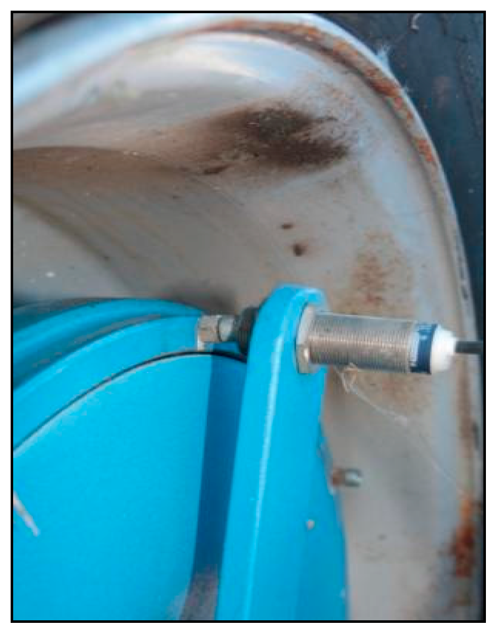
Figure 5.
Microprocessor and beeper.
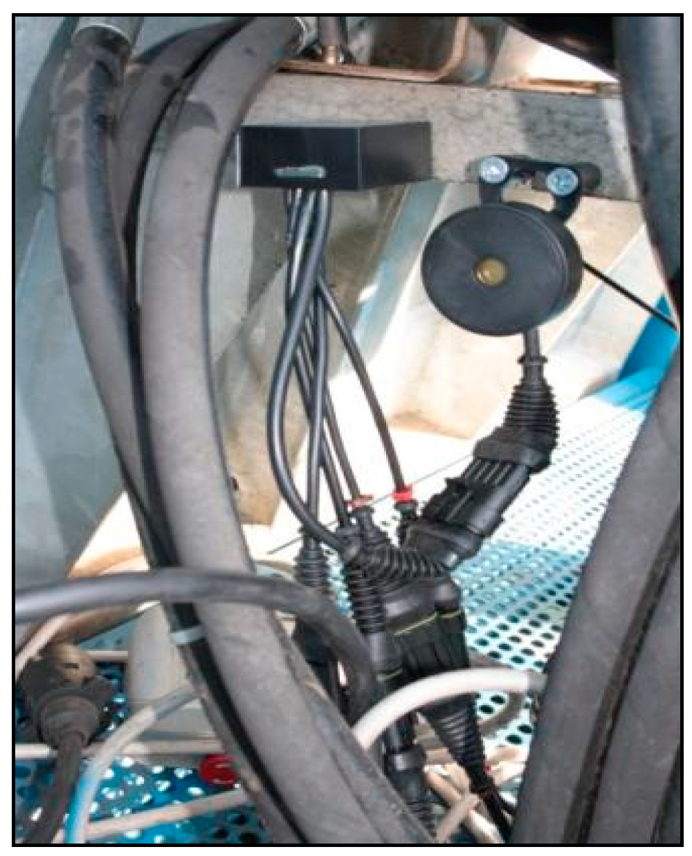
Figure 6.
Sensor on PTO.


Table 1.
Data for clutch dimensioning.
| Rotation Speed 1 (rpm) | Transmitting Torque (Nm) | Supply Voltage |
|---|---|---|
| 540 | 2200 | 12 |
| 1000 | 1600 | 12 |
1 depending on the model.
Table 2.
SWOT (Strengths, Weaknesses, Opportunities, and Threats) analysis regarding the decoupling device.
Table 2.
SWOT (Strengths, Weaknesses, Opportunities, and Threats) analysis regarding the decoupling device.
| Strengths | Weaknesses |
|---|---|
| Working organs stopped during cleaning and maintenance operations. | High component costs. High installation, assembly, and setup costs. |
| Possibility of a manual reset in a safe area. | Necessity of regulatory transposition and any objections by manufacturers. |
| Possibility to break the movements of the rotating parts with the aid of the tractor hydraulics. | Difficulties in adapting machines already on the market and in use. |
| Flow solenoid valve that facilitates the adjustment of the speed of the conveyor belts. | Not easily adaptable by small/middle builders. |
| The rotating sensor detects the wagon’s motion. | Need to adjust the speed of the conveyor belt. |
| Minor space displacement in the case of downstream positioning of the clutch. | Possible malfunctions and/or breaks of the various components. |
| Possibility to break the movements of the two transmission organs. | With clutch located downstream of the hydraulic unit, provide a stop mechanism for conveyor belts (risk of injury of the lower limbs if the chains remain in motion). |
| Electromagnetic clutches that can be powered by the electric voltage (12 V) of the tractor. | Requirements of a separate hydraulic circuit if hydraulic clutches are used. |
| Less expensive, less bulky, and easier to install and integrate electromagnetic clutch. | Low availability of 12 V clutches. |
| Separate tractor/wagon hydraulic circuits. | The need for a torque limiter. |
| Difficult system inactivation. | The need for a programmable logic controller (PLC). |
| Possible conflicts with electronic regulation systems. | |
| Not easily inserted in the ISOBUS technology. | |
| Opportunities | Threats |
| Robust, durable, and reliable system. | Procedural distortion in the production line. |
| Polyfunctional system for other types of machines (e.g., round baler that, together with manual reset, must only engage the machine when it is in motion). | Needing of specialized technical personnel. |
| Improved safety. | Possible rearmament of the system with the help of a second person or thing that keeps the hold-to-run control inserted. |
| Possible rearming of the motion of the rotating parts by means of hold-to-run control. | High risks if the movements are not disrupted. |
| Probable reduction of sensor costs. | Sensors relatively fragile. |
| Hydraulic pump driven by the PTO (power take off). | |
| The second stop mechanism makes the total costs rise. | |
| In the absence of a hydraulic unit, the application of a circuit causes considerable additional costs. | |
| PLCs and other microcomponents make the set relatively expensive and complex. | |
| Total costs not within the reach of all manufacturing companies. | |
| Field operational problems and possibility of frequent blockages due to clogging. |
Table 3.
Stop time recorded during test.
| Test No. | Stop Time (s) | Average Time (s) | Standard Deviation (s) |
|---|---|---|---|
| 1 | 13 | 12 | 0.707 |
| 2 | 12 | ||
| 3 | 11 | ||
| 4 | 12 | ||
| 5 | 12 |
Table 4.
Technical characteristics.
| Microprocessor |
|---|
| Software configuration: |
| - Alarm sound in case of moving organs in the absence of wagon advancement |
| - Block of the moving parts in the event of wagon stoppage |
| Hardware configuration: |
| - One standard output for the light or sound signal |
| - One standard output for unlocking the movement of the mechanical parts |
| - One digital input with 1 to 100 Hz bandwidth and 0/12 V amplitude for the running sensor |
| - One digital input with 1 to 100 Hz bandwidth and 0/12 V amplitude for active PTO sensor |
| Operating conditions: |
| - Power supply: 10/18 V DC with reverse polarity protection and overvoltage impulse |
| - Absorption: 5 mA (excluding signalling devices) |
| - Temperature: from −20 °C to +60 °C |
| - Maximum humidity: 90% non-condensing |
| - Protection: IP-65 |
| Proximity sensors |
| XS612 Sensor: |
| - Section: 53 mm |
| - Rated detection distance: 0.16 (4 mm) |
| - Discrete output function: 1 NO |
| - Output circuit type: AC/DC |
| - Rated voltage: 24 to 240 V AC/DC (50/60 Hz) |
| - Switching capacity current: 5 to 200 mA AC/DC |
| - Power supply limits: 20 to 264 V AC/DC |
| - Residual current ≤0.8 mA, open condition |
| - Switching frequency: ≤1000 Hz DC; ≤25 Hz AC |
| - Voltage drop: ≤5.5 V, closed condition |
| XS618 Sensor: |
| - Section: 62 mm |
| - Rated detection distance: 0.31 (8 mm) |
| - Discrete output function: 1 NO |
| - Output circuit type: AC/DC |
| - Rated voltage: 24 to 240 V AC/DC (50/60 Hz) |
| - Switching capacity current: 5 to 200 mA DC–5 to 300 mA AC |
| - Power supply limits: 20 to 264 V AC/DC |
| - Residual current: ≤0.8 mA, open condition |
| - Switching frequency: ≤1000 Hz DC; ≤25 Hz AC |
| - Voltage drop: ≤5.5 V, closed condition |
© 2017 by the authors. Licensee MDPI, Basel, Switzerland. This article is an open access article distributed under the terms and conditions of the Creative Commons Attribution (CC BY) license (http://creativecommons.org/licenses/by/4.0/).
Share and Cite
MDPI and ACS Style
Cecchini, M.; Monarca, D.; Laurendi, V.; Puri, D.; Cossio, F. Mechatronic Solutions for the Safety of Workers Involved in the Use of Manure Spreader. Agriculture 2017, 7, 95. https://doi.org/10.3390/agriculture7110095
AMA Style
Cecchini M, Monarca D, Laurendi V, Puri D, Cossio F. Mechatronic Solutions for the Safety of Workers Involved in the Use of Manure Spreader. Agriculture. 2017; 7(11):95. https://doi.org/10.3390/agriculture7110095
Chicago/Turabian StyleCecchini, Massimo, Danilo Monarca, Vincenzo Laurendi, Daniele Puri, and Filippo Cossio. 2017. "Mechatronic Solutions for the Safety of Workers Involved in the Use of Manure Spreader" Agriculture 7, no. 11: 95. https://doi.org/10.3390/agriculture7110095
Note that from the first issue of 2016, this journal uses article numbers instead of page numbers. See further details here.