Development of Broadband Underwater Radio Communication for Application in Unmanned Underwater Vehicles


1
Saltenna LLC, 1751 Pinnacle Drive, Suite 600, McLean, VA 22102-4903, USA
2
Electrical and Computer Engineering Department, University of Maryland, College Park, MD 20742, USA
*
Author to whom correspondence should be addressed.
J. Mar. Sci. Eng. 2020, 8(5), 370; https://doi.org/10.3390/jmse8050370
Submission received: 31 March 2020
/
Revised: 14 May 2020
/
Accepted: 18 May 2020
/
Published: 23 May 2020
(This article belongs to the Special Issue Unmanned Underwater Vehicles: Advances and Applications)
Abstract
:This paper presents several novel designs of small form factor underwater radio antennas operating in the 2 MHz, 50 MHz and 2.4 GHz bands. These antennas efficiently excite surface electromagnetic waves (SEW) which propagate along the surface of seawater. The antenna operation is made possible due to implementation of an impedance matching enclosure, which is filled with de-ionized water. Enhanced coupling to surface electromagnetic waves is enabled by the enhancement of the electromagnetic field at the antenna apex. These features allow us to make antenna dimensions considerably smaller compared to typical free space designs. They also considerably improve coupling of electromagnetic energy to the surrounding seawater. Since SEW propagation length is considerably larger than the skin depth in seawater, this technique is useful for underwater broadband wireless communication. We conclude that the developed broadband underwater radio communication technique will be useful in networking of unmanned underwater vehicles.
1. Introduction
Wide band communication remains the limiting bottleneck for command and control of unmanned underwater vehicles (UUV). Acoustic communication is bandwidth limited due to slow propagation speeds and is susceptible to high error rates due to multi-path effects. Conventional radio frequency (RF) signals may be used for wide bandwidth communications. However, they are severely limited in communication range due to rapid attenuation in seawater. Directional optical links are capable of providing bandwidth over 200 Mbps in seawater but, until now, have not been successfully integrated into operational UUVs due to the need for sophisticated pointing, acquisition and tracking. Moreover, water turbidity strongly affects performance of the optical links. As a result, the use of optical wireless communication for reliable UUV-to-UUV links remains highly challenging. Thus, underwater wide bandwidth wireless communication remains a critical technology gap that needs to be filled.
Very recently we have reported a novel design of a SEW RF antenna, which operates in the 2.4 GHz band and which efficient launches surface electromagnetic waves along an interface between a conductor and a dielectric [1]. The antenna operation is based on the strong field enhancement at the antenna tip, which results in efficient excitation of surface electromagnetic waves propagating along nearby conductive surfaces. It was demonstrated that this antenna may be used to send broadband radio communication signals through such conductive enclosures as commercial Faraday cages. It was also hypothesized that a similar design could be used for broadband underwater communication. Indeed, a successful adaptation of the surface wave antenna design was reported in [2] which operates in the 50 MHz band and is able for launch SEWs along the seawater surface. In addition to the enhancement of electromagnetic field near the antenna apex, the antenna design implements an impedance matching enclosure which uses de-ionized water [3]. This enclosure enables reduction of the antenna dimensions. It also improves coupling of electromagnetic energy to the surrounding seawater. Since the propagation length of SEW considerably exceeds the skin depth of radio waves at the same frequency, the surface wave technique may be used for underwater broadband wireless communication over long distances.
In this article, we report further development of this concept. We will describe several designs of portable underwater radio antennas operating in the 2 MHz, 50 MHz and 2.4 GHz bands, which can be used for efficient launching of SEWs along the seawater surface. In all cases, the developed surface wave underwater antennas are capable of broadband underwater wireless communication over distances which are much larger than the skin depth in seawater. We infer that the developed broadband underwater radio communication technique will be useful in communication among unmanned underwater vehicles.
2. Methods
Typically, it is impossible to establish RF communication through conductive media and enclosures, such as communication through seawater, metallic chambers, etc. Performance of conventional radio communication schemes in these geometries is limited by the very small skin depth δ of a conductive medium, which may be calculated as:
where ν is the communication frequency and σ is the medium conductivity [4]. In the case of seawater (3.5% salinity, 5 S/m conductivity), the frequency dependent RF skin depth may be estimated by
This effect severely limits the ability to use radio communication in seawater. For example, the skin depth of seawater at 50 MHz equals approximately 3.8 cm, so it is impractical to use conventional radio communication over useful distances. In addition, conventional RF signals cannot penetrate through small defects and openings in conductive barriers. For example, transmission of a conventional transverse electromagnetic wave through a subwavelength aperture was found by Bethe [5] to be equal to
where λ is the free space wavelength and a is the aperture size. It produces negligible transmission if a << λ. Therefore, conventional radio communication techniques are also impractical in situations where an enclosure is surrounded by conductive walls.
On the other hand, it is well established that efficient coupling to surface electromagnetic modes which exist at conductor/dielectric interfaces [6] enables efficient signal transmission through continuous conductive barriers (including even metal layers) and through deeply subwavelength apertures in such barriers [7,8]. Following this approach, we have designed a 2.45-GHz SEW antenna [1], which can transmit video signals from inside a −90 dB isolation Faraday cage. We believe that this novel ability may be utilized for remote examination of metal enclosures, as well as improving Wi-Fi connectivity in underground tunnels and buildings. Moreover, a similar surface electromagnetic wave-based approach may be used to implement broadband radio communication in seawater over long distances, which considerably exceed the skin depth of radio waves in seawater [2].
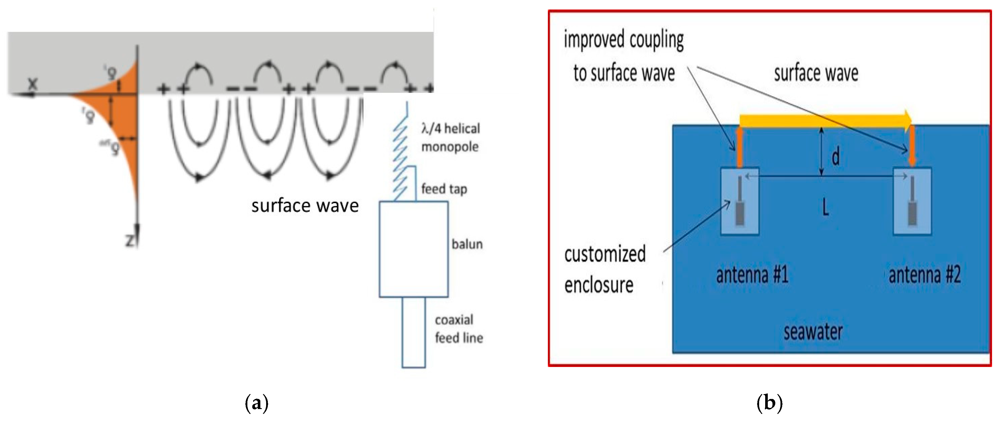
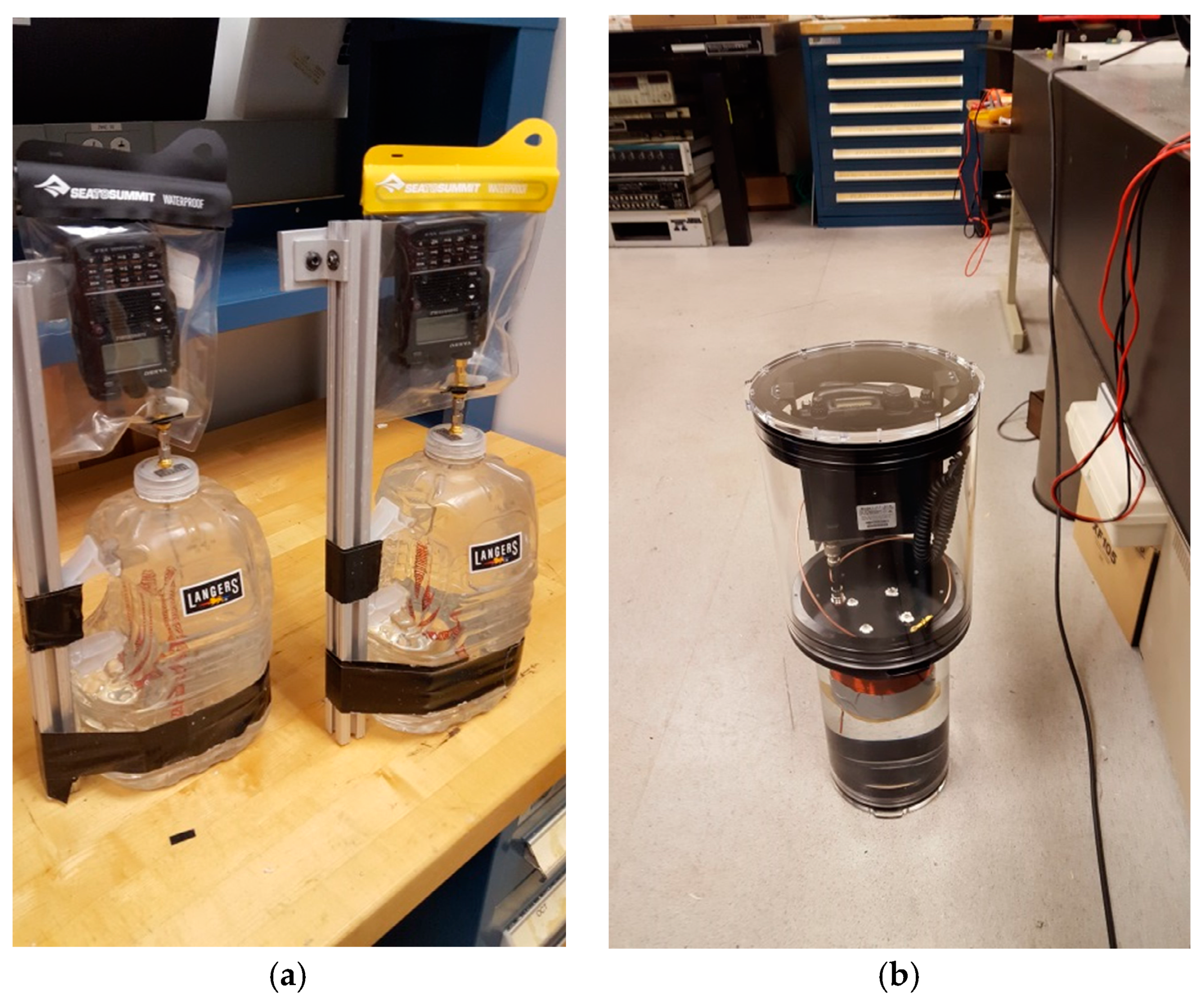
The operating principle of the SEW antenna is illustrated in Figure 1a. The electric field of the SEW has a nonzero component in the longitudinal direction, which means that a good SEW antenna needs to be located near of a conductive surface, and it needs to produce a strong field enhancement at its tip, which will push charges along the conductive surface. When such an antenna is adapted for surface wave-based underwater communication, it is encapsulated in an impedance matching enclosure, which is filled with de-ionized water, as illustrated in Figure 1b. This enclosure enables reduction of the antenna dimensions by approximately factor of 9 compared to the dimensions of similar antenna in free space. The enclosure also improves coupling of electromagnetic energy to the surrounding seawater, since compared to the air/seawater interface, an interface between de-ionized water and seawater is much better impedance-matched. In addition, it also reduces the ohmic losses which would arise due to the immersion of the antenna in seawater. Examples of such antenna designs optimized for operation in the 50 MHz and 2 MHz bands are presented in Figure 2.
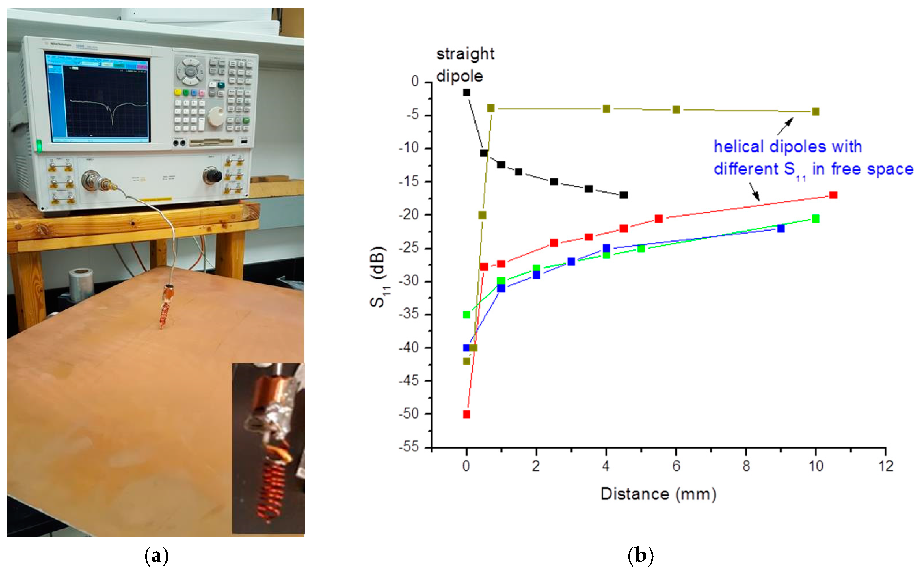
A tuning procedure of the surface wave antenna is illustrated in Figure 3. It illustrates measurements of S11 of the 2.45 GHz helical SEW antennas as a function of distance to a large planar conductive surface. As illustrated in Figure 3b, depending on the location of the tapping point, the radiative behavior of the antenna may be optimized for either surface wave radiation or radiation into free space. The antenna tuning was also checked by maximizing the received video signal outside a closed Faraday cage, as described in detail in [1]. A comprehensive description of antenna geometry shown in Figure 1a and its fabrication, tuning and testing may be found in [1,2].
3. Results
3.1. Broadband Transmission through Faraday Cage
The performance of the designed SEW antenna in the 2.4 GHz band has been tested by verifying Wi-Fi video signal transmission through a −90 dB isolation Faraday cage, as illustrated in Figure 4. The video signal was generated inside a locked Faraday cage and transmitted through free space live. There was no cabling or connecting ground between the transmitter and receiver. The video signal received outside the enclosure by a similar antenna at a distance on the order of 10 to 100 cm was displayed on a live TV monitor.
The surface wave mediated mechanism of 2.4 GHz video signal transmission has been verified by measurements of the transmitted signal near the Faraday cage as a function of distance from the outside wall of the cage [1]. The surface wave character of the transmitted signal was confirmed by an exponential decay of the transmitted signal outside of the cage. However, the signal received farther away from the cage was a conventional TEM signal, which originated due to the transmitted SEW field reaching the cage corners and scattering into the conventional TEM fields.
3.2. Broadband Underwater RF Communication Experiments in Laboratory Settings
It is obvious that the experiments with a Faraday cage depicted in Figure 4 above are topologically equivalent to the experiments with the same 2.4 GHz SEW antennas performed in a seawater aquarium, which are depicted in Figure 5. In these experiments, the seawater surrounding the Wi-Fi video transmitter (which is enclosed in a watertight plastic case) plays the role of a Faraday cage.
Note that the skin depth of seawater at 2.4 GHz is 3 mm, while the thickness of seawater layer around the watertight plastic case was at least 15 cm on each side. Note also that water turbidity did not affect video signal transmission, as illustrated in Figure 5b. Thus, similar to transmission through a Faraday cage, the SEW antenna clearly demonstrates increased capacity for Wi-Fi transmission through seawater. This increased capacity may be understood based on the theoretical values for SEW propagation length Lr along the seawater-air interface, and the penetration depth Lz of SEW field into the seawater [2]. Based on the detailed theoretical consideration in [6,9], they are given by the following expressions:
and
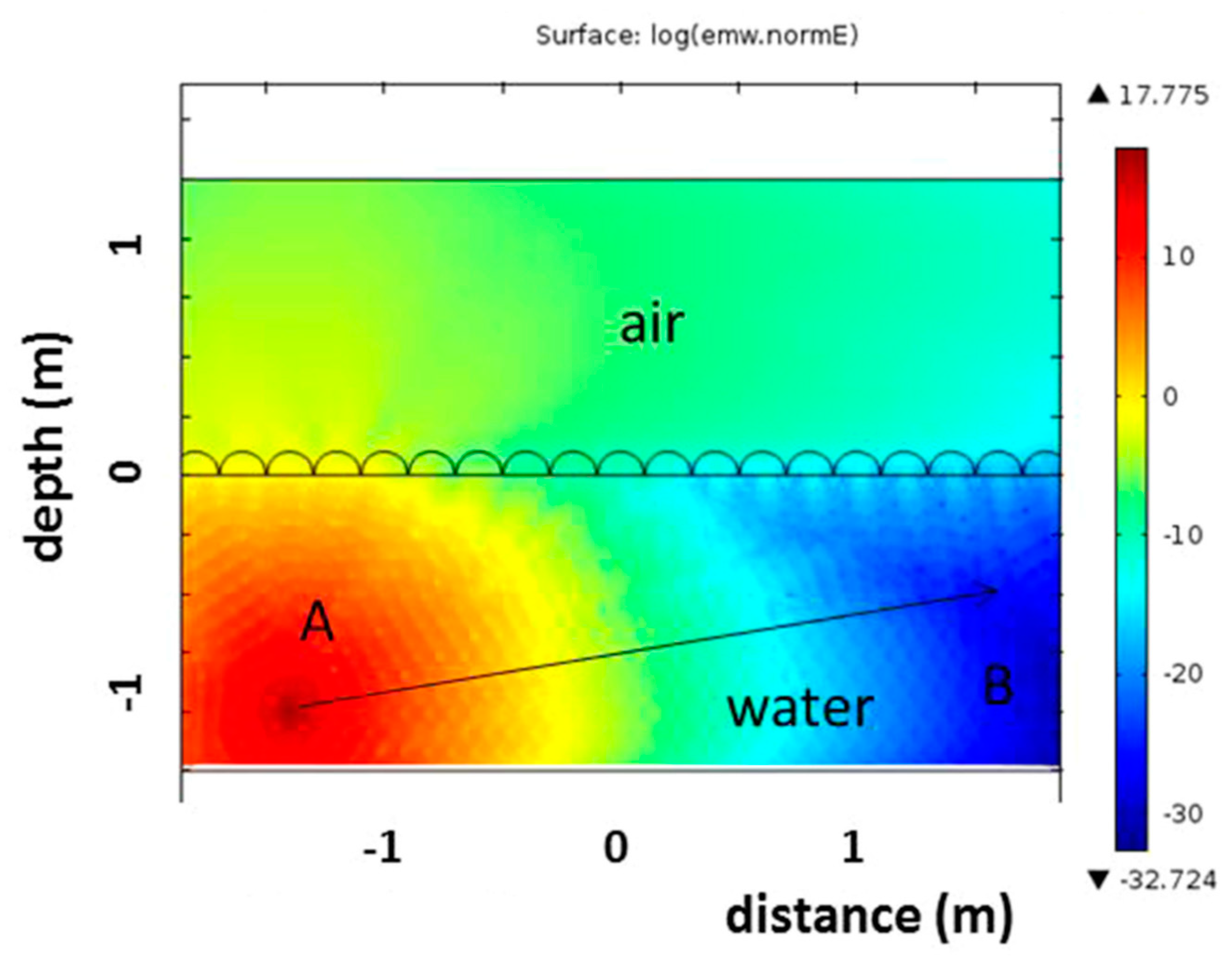
respectively [4], where λ0 is the free space wavelength, and ε” is the imaginary part of the dielectric constant of saltwater. For example, at 50 MHz the theoretical SEW propagation distance is quite large (Lr = 60 m), while the communication depth Lz may reach several meters assuming Tx operation down to −90 dB relative signal level. These distances appear to be much larger than the 3.8 cm skin depth of seawater at 50 MHz. These observations are illustrated in Figure 6, which demonstrates the radio field distribution near the seawater surface, which is produced by a point source of radio waves located near the air/seawater interface (these simulations were performed using the RF module of COMSOL Multiphysics). At some distance from a source (which is much longer than the bulk skin depth of seawater) the RF field is dominated by the SEW contribution, which enables radio communication from point A to point B. This communication would be impossible in the absence of the surface wave.
We should also note that waviness of the seawater–air interface may further promote coupling of the electromagnetic energy into the SEW modes. Such an increased coupling is well established in the closely related field of plasmonics [6], and it was observed in our model experiments performed in a seawater aquarium at 2.4 GHz (see Figure 7). These simple experiments indicate that an agitated sea state may not necessarily present a problem for SEW-based broadband underwater RF communication.
Directionality of SEW beams, which is also well known in plasmonics [6,10] may further improve performance of underwater RF communication links, since it may to some extent alleviate deterioration of link performance due to high propagation losses in seawater. We were able to demonstrate directional excitation and propagation of SEW waves in model experiments performed in a freshwater aquarium in laboratory settings, as illustrated in Figure 8.
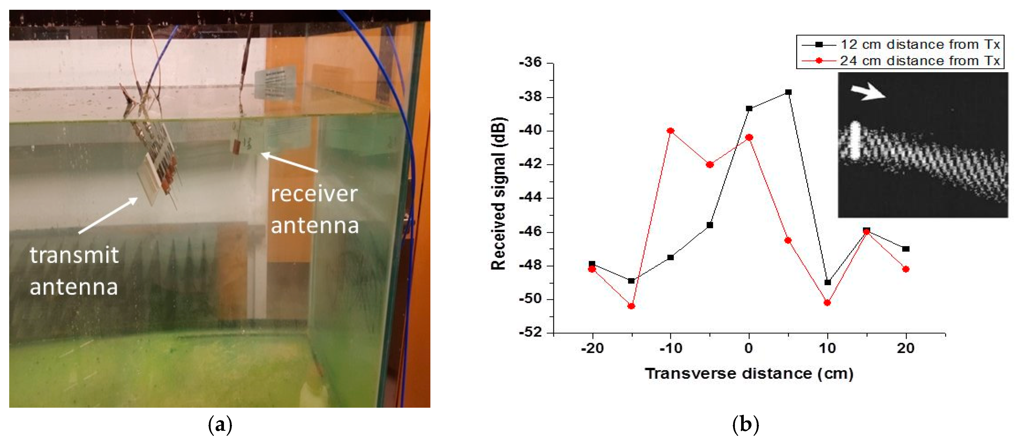
In these experiments, we have used an array of four dipole antennas spaced at 5 cm distances, which resonate at 2.4 GHz in air. After the array was submerged into a freshwater aquarium, its resonant frequency shifted to 400 MHz. The antenna array field was probed by a distant dipole receiver identical to individual antennas in the array, as illustrated in Figure 8a. It was verified that there was no relevant coupling between the feed lines above water. The antenna array field measured in the transverse direction at two distances from the array is plotted in Figure 8b, which also shows our numerical modeling of SEW beaming.
3.3. Field Testing of Broadband Underwater RF Communication
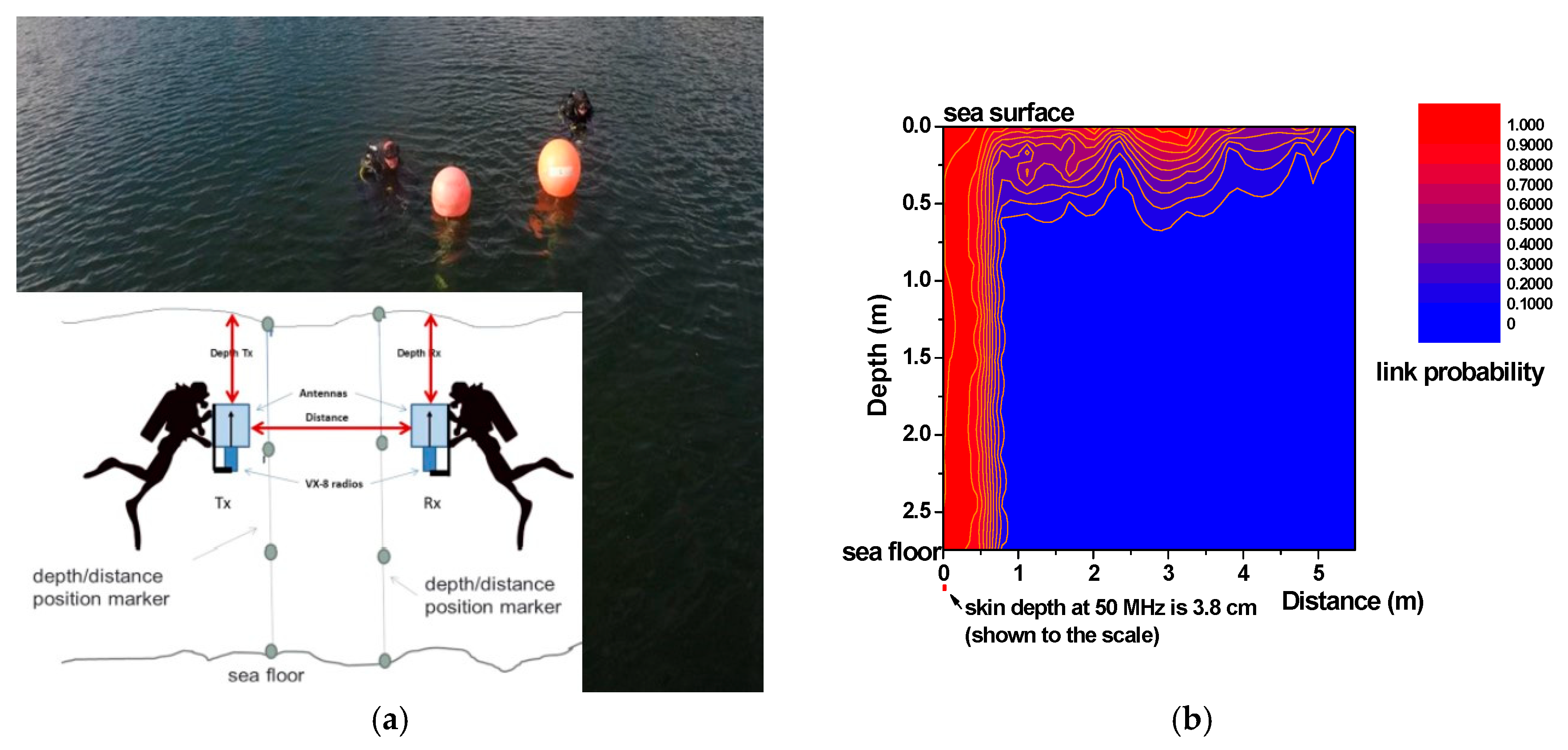
The field performance of the developed SEW antennas has been tested at an underwater testing facility near Panama City, Florida (average water salinity 3.0%) [2]. The SEW antennas were tested in the 50 MHz band. The seawater testing environment was sufficiently large, so that no significant boundary effects were present. These tests were conducted using separate battery-operated transmitting (TX) and receiving (RX) antenna and radio systems, which were enclosed in watertight containers shown in Figure 2a. The underwater radio systems were operated by divers as illustrated in Figure 9a. The divers verified their respective depth and distance from each other using fixed markers made of buoys and ropes. The signal propagation data were read by the divers from the LED indicator and the S-meter of the Yaesu radios. These data were reported by the divers to the test personnel, which was located on a nearby vessel. The measured averaged measured link probability data are plotted in Figure 9b. The skin depth at 50 MHz in seawater (3.8 cm) is shown near the bottom left corner of the plot for comparison. These results clearly demonstrate that the novel underwater SEW antennas described above enable radio communication over range/depth combinations which go far beyond the known skin depth of seawater. Note that the relatively large variations of the link probability observed in our experiments may be explained by the variations in seawater salinity during the experiments and changes in the sea state (the seawater ripples), bubbles and biological objects, which scatter the surface electromagnetic waves.
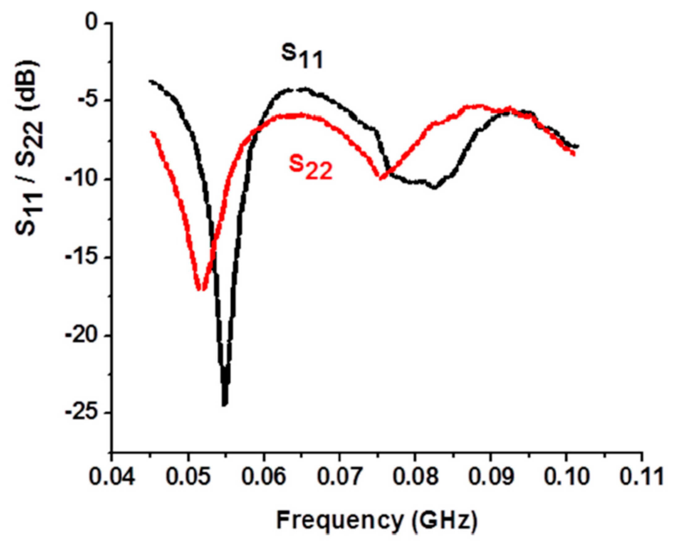
The underwater experiments depicted in Figure 9 were conducted without any external cables, in order to exclude any possibility of a spurious crosstalk. All the transmitter and receiver radios and antennas were placed underwater as shown in the inset in Figure 9a. In the absence of a network analyzer underwater, the values of S11 and S22 were not measured during the experiments depicted in Figure 9. However, these values were measured in the lab in a seawater tank, as depicted in Figure 10.
While the observed SEW signal propagation at 50 MHz was considerably below the theoretically projected Lr = 60 m, we anticipate that further optimization of the SEW antenna will result in reaching the theoretical depth and distance limits, which are described by Equations (4) and (5). These performance limits are summarized in Table 1 for the set of RF bands explored in this paper. Note that predictions given by Equation (5) may not be reliable at smaller frequencies due to the fact that it was derived for a planar conductor-dielectric interface.
4. Discussion and Conclusions
The communication distance/depth combinations summarized in Table 1 provide quite an optimistic outlook for potential applications of SEW antennas in underwater communication between divers and UUVs, since even larger communication depth may be achieved at lower frequencies. For example, it appears that Lz~15 m is achievable in the 0.1 MHz band at quite modest 5 W transmit power. Our experimental and theoretical results appear to be novel and important since, until very recently, the general belief was that broadband RF communication through seawater is impossible over any practical distance. We anticipate that further development of SEW antennas and further optimization of the antenna parameters will result in reaching the theoretical limits on underwater depth and communication distance, which are described by Equations (4) and (5). These developments will enable novel technology for wide bandwidth radio signal communication through seawater. We should also note that our SEW-based RF communication scheme should be able to breach the seawater barrier for UAV to UUV communication, since the surface wave EM field is present both above and below the seawater surface. This would enable, for example, a drone skimming the surface of the water to pick up signal transmitted from a UUV. The described antennas may also be made multi-spectral so that the communication bandwidth at a given distance/depth combination may be optimized under software control, shifting to larger bandwidths over shorter distances. Our communication scheme may also find applications in frogman to frogman communication, underwater object detection, UUV swarming and mesh networked UUVs, offshore oil platforms, etc. We also expect that our technology will enable considerable improvements in Wi-Fi connectivity in buildings and underground tunnels. Remote examination of metal and partially metal enclosures, such as shipping containers and metallic test chambers, should also become possible in the near future.
Author Contributions
I.S., Q.B. and D.Y. contributed equally to this work. All authors have read and agreed to the published version of the manuscript.
Funding
This research received no external funding.
Conflicts of Interest
The authors declare no conflict of interest.
References
- Smolyaninov, I.I.; Balzano, Q.; Young, D. Surface wave-based radio communication through conductive enclosures. Prog. Electromagn. Res. M 2019, 85, 21–28. [Google Scholar] [CrossRef] [Green Version]
- Smolyaninov, I.I.; Balzano, Q.; Davis, C.C.; Young, D. Surface wave-based underwater radio communication. IEEE Antennas Wirel. Propag. Lett. 2018, 17, 2503–2507. [Google Scholar] [CrossRef] [Green Version]
- Smolyaninov, I.I. Communication and Sensor Techniques for Underwater Radio Communication. U.S. Patent Application Publication # US 20180198536, 7 December 2018. [Google Scholar]
- Cheng, D.K. Fundamentals of Engineering Electromagnetics; Pearson: London, UK, 1992; Chapter 8. [Google Scholar]
- Bethe, H.A. Theory of diffraction by small holes. Phys. Rev. 1944, 66, 163–182. [Google Scholar] [CrossRef]
- Zayats, A.V.; Smolyaninov, I.I.; Maradudin, A. Nano-optics of surface plasmon-polaritons. Phys. Rep. 2005, 408, 131–314. [Google Scholar] [CrossRef]
- Ebbesen, T.W.; Lezec, H.J.; Ghaemi, H.F.; Thio, T.; Wolff, P.A. Extraordinary optical transmission through sub-wavelength hole arrays. Nature 1998, 391, 667–669. [Google Scholar] [CrossRef]
- Elliott, J.; Smolyaninov, I.I.; Zheludev, N.I.; Zayats, A.V. Polarization control of optical transmission of a periodic array of elliptical holes in a metal films. Opt. Lett. 2004, 29, 1414–1416. [Google Scholar] [CrossRef] [PubMed] [Green Version]
- Michalski, K.A.; Mosig, J.R. The Sommerfeld half-space problem revisited: From radio frequencies and Zenneck waves to visible light and Fano modes. J. Electromagn. Waves Appl. 2016, 30, 1–42. [Google Scholar] [CrossRef] [Green Version]
- Smolyaninov, I.I.; Mazzoni, D.L.; Davis, C.C. Imaging of surface plasmon scattering by lithographically created individual surface defects. Phys. Rev. Lett. 1996, 77, 3877–3880. [Google Scholar] [CrossRef] [PubMed]
Figure 1.
Operation of the SEW antenna near a conductor/dielectric interface where the antenna is placed either on the dielectric (air) side of the interface, or on the conductor (seawater) side near the interface: (a) Schematic geometry of a 2.4 GHz surface wave antenna design based on helical monopole shorted to its feed line outer conductor. The tip of the antenna is shown near a flat conductive surface where it excites an omnidirectional surface electromagnetic wave. The electromagnetic field of the surface electromagnetic wave is partially longitudinal, which means that an efficient surface wave antenna needs a strong field enhancement at its apex, which “pushes” charges along the metal surface; (b) Principle of operation of a similar underwater surface electromagnetic wave RF transmitter.

Figure 2.
(a) SEW underwater antennas attached to Yaesu VX-8 radios operated at 50 MHz. The impedance-matching enclosures are filled with de-ionized water; (b) Assembled surface wave underwater antenna operating in the 2 MHz band attached to a Yaesu FT-857 radio operated at 5 W output power. The impedance-matching enclosure (seen in the bottom section of the assembly) is filled with de-ionized water.

Figure 3.
(a) Measurements of S11 of the fabricated helical antenna resonant at 2.45 GHz near a large copper plane. The micro-positioning stage is located below the copper plane. The inset shows a photo of the antenna; (b) Tuning of the fabricated helical antennas resonant at 2.45 GHz via measurements of S11 as a function of distance from the large copper plane. The tuning parameter is the tapping point of a feeding coaxial line. The red, green and blue curves correspond to different positions of the tapping point on the same antenna. Behavior of a conventional dipole antenna is presented for a comparison.

Figure 4.
(a) SEW antenna maintains transmission of video signal from a locked −90 dB Faraday cage (JRE Test, model 0709). (b) Conventional dipole antenna cannot transmit the video signal when used in the same experimental configuration.
Figure 4.
(a) SEW antenna maintains transmission of video signal from a locked −90 dB Faraday cage (JRE Test, model 0709). (b) Conventional dipole antenna cannot transmit the video signal when used in the same experimental configuration.

Figure 5.
(a) Similar to experiments depicted in Figure 4, a 2.4 GHz surface wave antenna transmits video signal from inside an aquarium filled with seawater; (b) The video transmission is not affected by water turbidity.
Figure 5.
(a) Similar to experiments depicted in Figure 4, a 2.4 GHz surface wave antenna transmits video signal from inside an aquarium filled with seawater; (b) The video transmission is not affected by water turbidity.

Figure 6.
Numerical simulations of radio field distribution near the air/seawater interface, which is produced by a point source located near the sea surface. At large distances from a SEW antenna, the field is dominated by the SEW contribution. These simulations were performed using COMSOL Multiphysics solver.

Figure 7.
(a) The Wi-Fi underwater video transmitter is moved beyond the free space communication range in a seawater aquarium with still water surface; (b) The video link is re-established when the seawater surface is agitated.
Figure 7.
(a) The Wi-Fi underwater video transmitter is moved beyond the free space communication range in a seawater aquarium with still water surface; (b) The video link is re-established when the seawater surface is agitated.

Figure 8.
(a) 400 MHz SEW field of an antenna array submerged into a fresh-water aquarium is probed by a distant dipole receiver; (b) Antenna array field measured in the transverse direction at 12 and 24 cm from the array. The inset shows numerical modeling of SEW directional beaming from the antenna array.

Figure 9.
(a) Photo of the underwater test range used in our experiments. The inset shows experimental configuration; (b) Contour plot of the link probability measured in seawater as a function of diver depth and distance between the divers. The sea floor was located at 9 m depth. The skin depth at 50 MHz in seawater is shown to the scale.

Figure 10.
S11 and S22 of the antennas used in the experiments depicted in Figure 9. These parameters were measured in the lab in a seawater tank. A de-ionized water antenna enclosure was implemented during these measurements.
Figure 10.
S11 and S22 of the antennas used in the experiments depicted in Figure 9. These parameters were measured in the lab in a seawater tank. A de-ionized water antenna enclosure was implemented during these measurements.


Table 1.
Summary of the theoretically predicted propagation range Lr and communication depth Lz (@ 5W transmit power) at the RF bands explored in this paper.
Table 1.
Summary of the theoretically predicted propagation range Lr and communication depth Lz (@ 5W transmit power) at the RF bands explored in this paper.
| 2.4 GHz Band | 50 MHz Band | 2 MHz Band | |
|---|---|---|---|
| Lz | 0.054 m | 0.7 m | 3.5 m |
| Lr | 3.8 m | 60 m | 900 km 1 |
1 Theoretical numbers given by Equation (5) may not be reliable in this band due to Earth curvature.
© 2020 by the authors. Licensee MDPI, Basel, Switzerland. This article is an open access article distributed under the terms and conditions of the Creative Commons Attribution (CC BY) license (http://creativecommons.org/licenses/by/4.0/).
Share and Cite
MDPI and ACS Style
Smolyaninov, I.; Balzano, Q.; Young, D. Development of Broadband Underwater Radio Communication for Application in Unmanned Underwater Vehicles. J. Mar. Sci. Eng. 2020, 8, 370. https://doi.org/10.3390/jmse8050370
AMA Style
Smolyaninov I, Balzano Q, Young D. Development of Broadband Underwater Radio Communication for Application in Unmanned Underwater Vehicles. Journal of Marine Science and Engineering. 2020; 8(5):370. https://doi.org/10.3390/jmse8050370
Chicago/Turabian StyleSmolyaninov, Igor, Quirino Balzano, and Dendy Young. 2020. "Development of Broadband Underwater Radio Communication for Application in Unmanned Underwater Vehicles" Journal of Marine Science and Engineering 8, no. 5: 370. https://doi.org/10.3390/jmse8050370
Note that from the first issue of 2016, this journal uses article numbers instead of page numbers. See further details here.