
Technical Problem Identification for the Failures of the Liberty Ships

1
Mine Management Division, Department of Mining & Mineral Resources, Chinalco China Copper Corporation Limited, Beijing 100082, China
2
Department of Mining and Materials Engineering, McGill University, Montreal, QC H3A 0C5, Canada
Challenges 2016, 7(2), 20; https://doi.org/10.3390/challe7020020
Submission received: 25 August 2016
/
Revised: 31 October 2016
/
Accepted: 1 November 2016
/
Published: 8 November 2016
Abstract
:The U.S. Liberty Ship Building Program in World War II set a record—a total of 2700 Liberty Ships were built in 6 years, in order to support the battle against Nazi-Germany. However, numerous vessels suffered sudden fracture, some of them being split in half. This paper demonstrates and investigation of the Liberty Ships failure and problems, which reveals that the failures are caused by a combination of three factors. The welds produced by largely unskilled work force contain crack type flaws. Beyond these cracks, another important reason for failure associated with welding is the hydrogen embitterment; most of the fractures initiate at deck square hatch corners where there is a stress concentration; and the ship steel has fairly poor Charpy-Impact tested fracture toughness. It has been admitted that, although the numerous catastrophic failures were a painful experience, the failures of the Liberty Ships caused significant progress in the study of fracture mechanics. Considering their effect, the Liberty Ships are still a success.
1. Historical Background
The battle predominantly of England and France against Germany during World War II caused a tremendous usage of resources in these two countries: mostly ammunition, food, oil and fuel. Starting in early 1941, neither England nor France was able to cover these demands themselves. To support the battle against Nazi-Germany, the United States provided mostly England and France, but later also Australia and New Zealand, which were fighting Japan in the Pacific, with various war-related supplies.
Since all these supplies had to be transported across either the Atlantic or the Pacific, a large fleet of cargo ships was required [1]. In the late 1930s, 90% of the Unites States’ fleet of large merchant vessels, however, was over 20 years old and neither in number nor in cargo capacity and speed capable of facing this challenge. In order to meet the demand for cargo ships, the United States started an emergency shipbuilding program in 1940 [2].
In this program, 16 U.S. shipyards produced over 2700 all-welded lightly armed cargo ships, tankers and other vessels between 1941 and 1946; all these ships are referred to as the Liberty Ships. The centerpiece of the fleet was a 135 m long cargo ship. Although this fleet was used for war purposes only, it was never part of the U.S. Navy.
The production of such a large number of ships with an insufficient number of skilled workers required the ships all to be of one single and very simple design. Companies and workers that had never before dealt with marine applications prefabricated large numbers of parts outside the dry-docks, which were then only assembled in the actual ship-yard. In order to increase the cargo capability of the vessels and to accelerate the production process, the design plan was such that the ships were to be all-welded, rather than riveted [1,2].
Although people credit the Liberty Ships with “saving the world from disaster”, many of these ships sank [1]. Most of them sank due to German torpedo attacks, even though a later design change allowed for a concrete lining on the inside of the entire hull from the bottom up to three feet above waterline [2]. However, numerous vessels suffered sudden fractures, which at that time were unexplainable. Some of the fractures were so severe that the ships broke into two pieces and had to be abandoned. Others could be repaired—some of them by assembling the stern of one and the bow of another Liberty Ship, only being possible owing to the simple mass production design.
2. Two Case Studies
Although most Liberty Ships were sunk by means of war, a significant number of them failed with sudden fractures that raised questions. To discuss the reasons for these failures, the representative fates of two different ships will be discussed.
2.1. The “John P. Gains”
The John P. Gains was assembled at the Oregon Ship Building Corporation in Portland in July 1943. On its way from Dutch Harbor in the Aleutian Islands to Seattle (WA), less than six months after its completion, the vessel fractured as the air temperatures hovered around 0 °C and a large swell washed over the port bow. The exact fracture origin could not be determined; however, it is assumed that, as in 52% of all serious fractures on Liberty Ships [1], it originated at the corners of the cargo hatches. Also noticeable is that the crack propagated not along welds but straight through the plating. Ultimately, the ship completely split in two parts; its bow presumably sank, while the stern drifted ashore in Alaska [1].
2.2. The “Schenectady”
Other than the John P. Gaines, the T2-tanker Schenectady failed after being docked in the port of Portland (OR), only a few days after completing sea trials. Again, air and water temperatures were cold; however, the ship was unloaded and in calm water. The fracture extended through the deck, the sides of the hull, the longitudinal bulkheads and the bottom girders, only hinging on the bottom plate (Figure 1).
An Investigation requested by the U.S. Coast Guard showed that the fracture originated at a defective weld. Such a fracture is characteristic of dry freighters. A common loading condition known as “hogging” is due the distribution of more weight towards the ends of the ships. This causes the ends of the ship to dip compared with the center, resulting in tensile forces on deck, and compressive forces at the keel. The deck will experience the maximum tensile stress.
3. The Theory behind It
In order to understand the reasons for the failure of so many Liberty Ships, it is necessary to understand some fracture mechanics.
3.1. Theoretical Background on Fracture Mechanics
For ductile materials, there is a critical combination of stress and crack length leading to instable crack growth and catastrophic failure. Ductile failures are associated with large amounts of plastic deformation. As a result of plastic deformation, localized necking or distortion is often present. In contrast to ductile failures, brittle fracture usually occurs without any noticeable deformation. Brittle fractures are generally flat, with little or no evidence of localized necking. The brittle fractures are characterized by rapid crack propagation, which occurs with sonic speed and perpendicular to the direction of the applied tensile stress [4].
In most cases of brittle fracture of crystalline materials, crack propagation is transgranular by successive and repeated breaking of atomic bonds along specific crystallographic planes (split planes). In case of significant segregations on the grain boundaries, the crack can also propagate in an intergranular way [4]. Factors promoting brittle failures are:
- High yield strengths that allow storage of high elastic energy level;
- Low temperature that cause a ductile-to-brittle transition in BCC metals;
- Large grain sizes that build up stress from dislocation pileups;
- High strain rates that do not allow time for stress redistribution;
- Coarse carbides or other inclusions that are themselves susceptible to cracking;
- Deep notches that create constraint at the crack tip;
- Thick sections that cause plane-strain loading.
3.1.1. Principles of Fracture Mechanics
Fracture mechanics, which have only been developed after the occurrence of a series of unexplainable brittle failures, allows us to quantify the relationship between materials properties, stress levels, the presence of crack-producing flaws and crack propagation mechanisms.
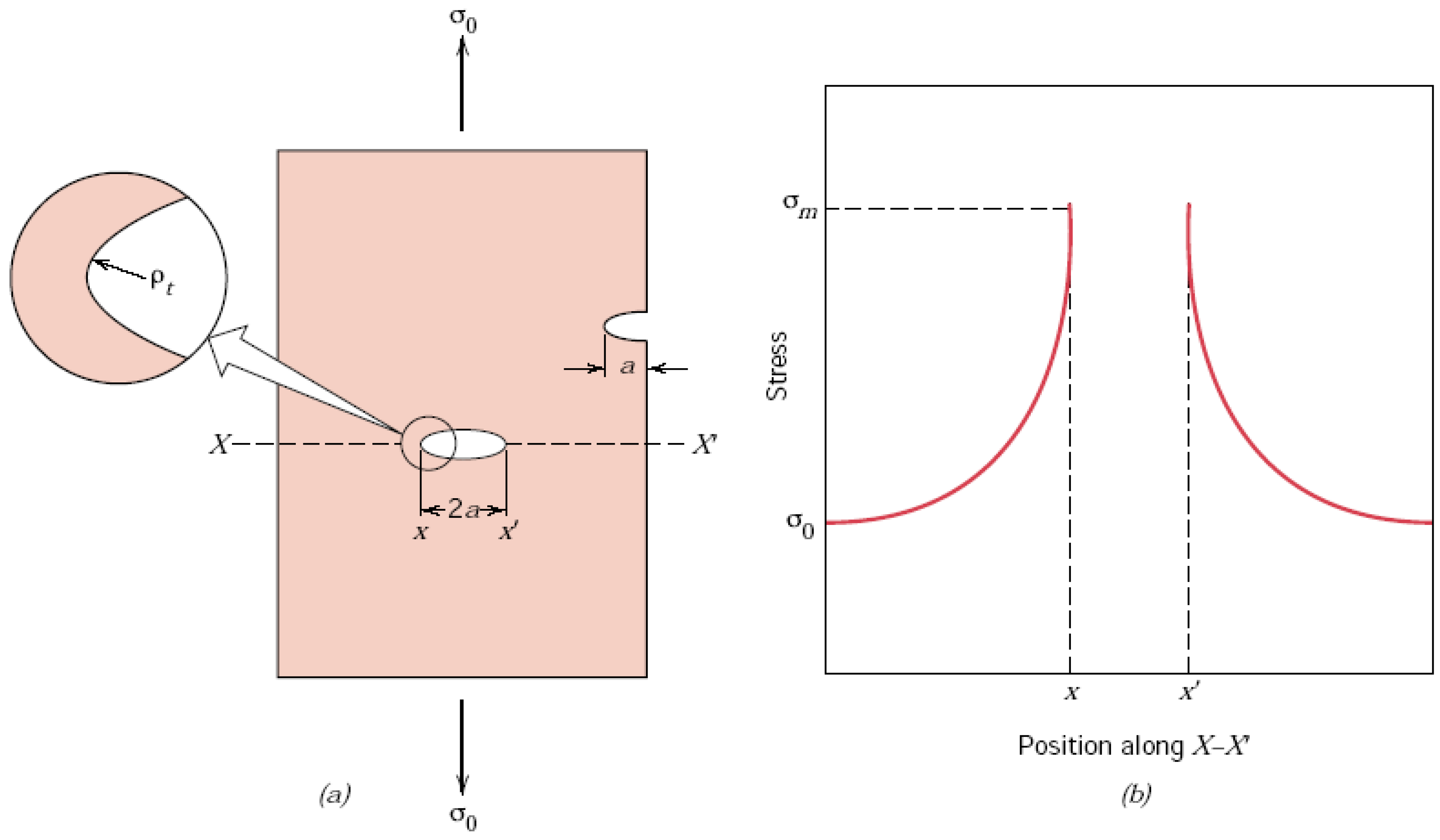
The strength of a material is a function of the cohesive forces between the atoms; however, the actual material strength is usually at least 10 to 1000 times below this theoretical value. According to Griffith, who predominantly studied amorphous and ceramic materials, this discrepancy between theoretical and observed fracture strength can be explained by the presence of very small, microscopic flaws and cracks that always exist under normal conditions [4]. In a stressed component, the stress has to amplify at the flaw or crack since this area cannot transmit any forces. Hence, the actual localized maximal stress, which appears at the tip of the flaw or crack is a multiple of the nominal applied stress. Furthermore, the sharpness of a crack tip has significant influence on the material behavior as the tip of the crack alters the stress mode from a unidirectional tensile load to a multiaxial stress mode (Figure 2).
Therefore, these flaws and cracks are sometimes called stress raisers; the ratio of maximal stress divided by the nominal applied tensile stress is called the stress concentration factor. Stress concentration is deemed as one of the major factors influencing fracture resistance in materials and complex structures. This stress concentration caused localized areas of high stress, which contributed to the brittle fracture of the ships. Local design should consider the design of critical structural details for reduction of stress concentrations and for producibility. Stress concentration is not restricted to microscopic flaws; in fact, this also applies to macroscopic discontinuities such as sharp changes of diameter, sharp corners or notches.
3.1.2. Fracture Toughness
It is important to note that the effect of stress raisers is much more significant in brittle than in ductile materials. If the maximum stress exceeds the yield strength of ductile materials, plastic deformation reduces the sharpness of the crack tip towards a blunt, rounded tip. This leads to a more uniform distribution of the stress in the vicinity of the flaw and the maximum stress concentration factor is lower than the theoretical value. In brittle materials, such a redistribution of stress is not possible as the theoretical yield strength of the material is higher than the ultimate tensile strength. A crack will propagate once the maximal stress exceeds the cohesive strength of the atoms at the tip of the flaw. This results in an increase of the crack size and a consequent increase of the stress concentration factor. Therefore, a propagating crack in a brittle material cannot be stopped, and will proceed through the entire member of the structure.
The critical value for fracture is fracture toughness. The key element of the fracture toughness is that it relates the applied stress conditions, flaw size, and the material’s fracture resistance. Generally, the relation between fracture toughness K, critical stress σC and crack length a are written as follows:
where Y is a constant related to crack geometry and specimen/loading parameters.
3.1.3. Ductile-To-Brittle-Transition
Under certain circumstances, materials that generally show ductile behavior can lose their fracture toughness and become brittle, likely resulting in catastrophic failure. Such circumstances can be fulfilled, if the crack length in a component is large enough that an applied stress is supercritical even with a fairly high fracture toughness that one would usually consider ductile.
Brittle behavior of usually ductile materials is probably more commonly experienced under the following circumstances:
- BCC or HCP metal;
- Low temperatures being;
- Loaded with high strain rates under tensile stress with significant stress concentration often coinciding with multiaxial stress mode.
Applying high strain rates results in the raising of the yield-point of a material; sometimes, it can be raised by as much as a factor of three, compared with the static test. Under these conditions, the yield point is likely raised above the ultimate tensile strength of the material. This means that the material will suffer a catastrophic fracture, before it would yield [5].
The raising of the yield-point is caused by the delay-time to yield. This time increases at lower temperatures as less activation energy is available for the motion of dislocations in slip planes. Furthermore, a change in the mechanism of deformation can be observed; a normal slip is superseded by the formation of twins, and the yield-point strain is reduced. The result of these observations is a lowered impact absorption capacity at low temperatures.
The higher susceptibility of Body Centered Cubic (BCC) and Hexagonal Close Packed (HCP) structured metals to brittle failure in comparison to Face Center Cubic (FCC) structured metals is based on the lower activation energy needed in FCC metals in order to move a dislocation in the closest packed plane. Although BCC and FCC crystals have the same amount of slip systems, the activation energy for these slip systems is higher in BCC metals due to the longer distance between two energy minima [6].
3.1.4. Impact Fracture Testing
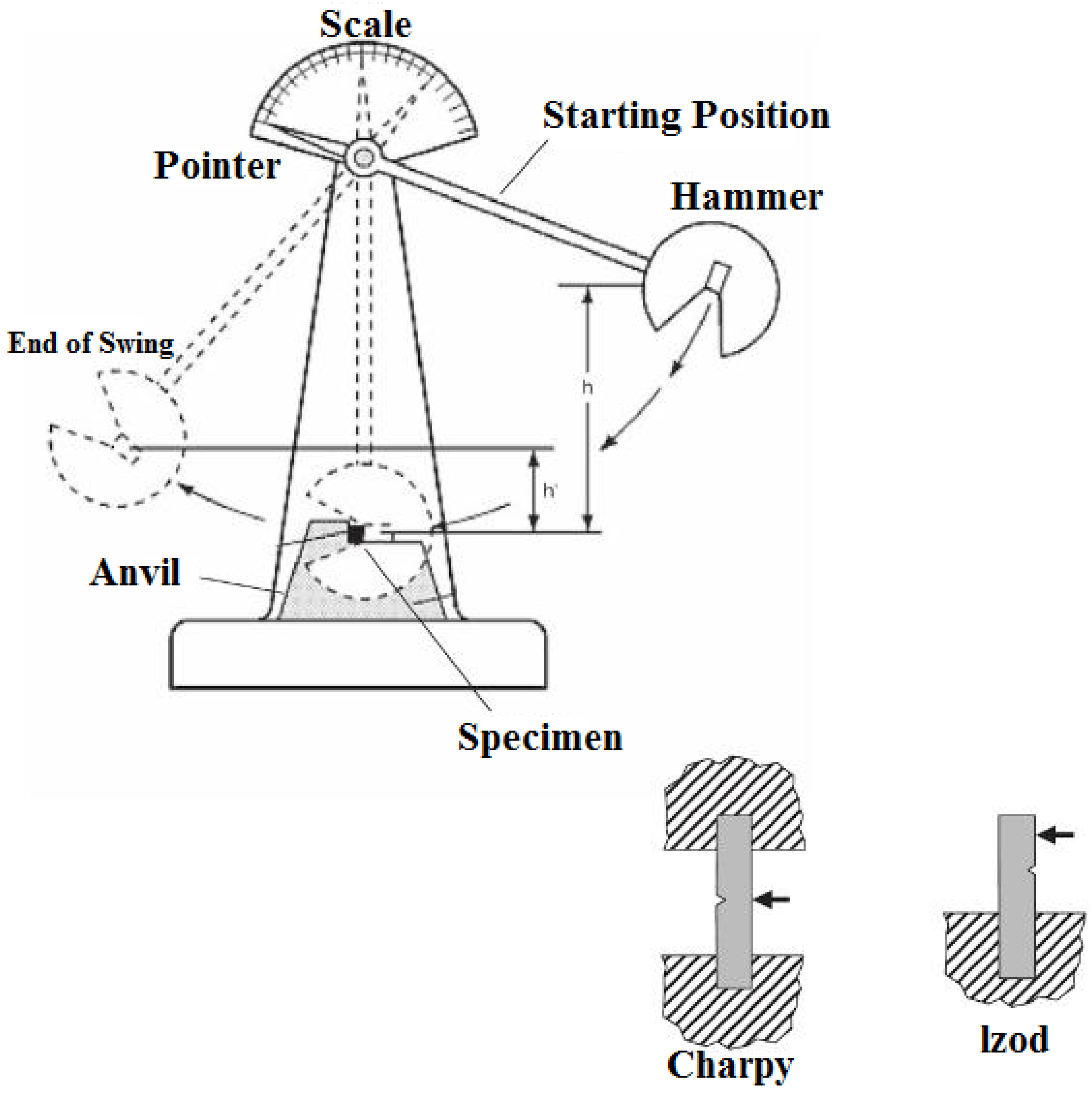
For these reasons, slow strain rates tests such as tension or torsion tests at room temperature alone are not sufficient to investigate the mechanical properties of materials. The discovery of these connections resulted in the development of additional testing techniques such as the Charpy-Impact Test (Figure 3). By means of a pendulum that loads a notched sample by means of a high strain rate, it tests the energy absorbed by the sample during fracture by measuring the height the pendulum reaches after the impact on the sample [2]. The difference in potential energy of the pendulum equals the energy that has been absorbed by the sample during the fracture. Materials that have high toughness absorb a lot of energy when fractured whereas brittle materials absorb very little energy. As this is a simple and quick test, it is suitable for investigations of fracture toughness at varying temperatures, which are needed for determination of the ductile-to-brittle temperature of susceptible materials.
3.2. Explanation of the Failures
Knowing the fracture mechanics, the failure of the John P. Gaines can be credited to brittle fracture for three main reasons. Many studies indicate that steel quality was the primary factor that contributed to the brittle facture in the structure [4]. Due to the general steel shortage at that time, high quality steel was barely available during World War II. Consequently, the mild steel utilized for the Liberty Ships did not comply with modern impact absorption standards. The brittle fracture was actually caused because the grade of steel used failed due to embrittlement. Secondly, mechanical considerations also suggest that the decking of the Liberty Ships, which was not from timber as was usual at that time but from steel plating, was under in a multixial stress in the vicinity of the cargo hatches. As explained, this promotes the rising of the ductile-to-brittle transition temperature, particularly under high strain rate loads such as the impact of heavy sea [7].
The Schenectady also failed in a brittle manner, and, again, the poor steel quality, which tends to brittle behavior in cold conditions, is one of the reasons for the failure [8]. However, in case of the Schenectady, another factor adds to the reasons: The Liberty Ships were all-welded constructions, which was a new technology at that time. This process was implemented to speed up the production and increase the cargo capacity by reducing the vessel’s dead load. However, the shortage of skilled workers is the reason why insufficiently trained personnel were employed as welders, resulting in poor weld quality. In this case, significant flaws in the welds acted as stress raisers causing the fracture to start [3].
Some references [9,10] also quote hydrogen embrittlement due to poor welding as another reason for the failures. Hydrogen embrittlement is mostly caused by electrode welding in wet or damp conditions. Although, from the authors’ case knowledge, this cannot be excluded, it does not appear to be a dominant reason, since the reasons mentioned already cause the material to behave in a brittle manner.
The steels utilized for the Liberty Ships were known to be acceptable for riveted ships; however, a propagating crack in riveted constructions will be stopped at the latest once it arrives at a joint between two plates, since these two plates are laying over one another. In a weld in contrast, two plates are joined via metallic bonding; a propagating crack will therefore not be stopped by a weld, but go right through it. Hence, all-welded constructions rely on high fracture toughness of the material even at low temperatures. Although this problem remained not entirely understood, riveted seam straps across the deck were added to prevent cracks from propagating.
4. Conclusions
Today, more than 60 years later it is hard to give suggestions. It is apparent that a steel quality that had a higher fracture toughness at low temperature would have prevented many ships from failing; it is also obvious that more experienced and better educated welders could have produced welds without or at least with fewer and smaller flaws. Today, it is commonly understood that rectangular corners have to be avoided in order to prevent stress concentration. However, considering the constraints of that time, considering the fact that large cargo ships were needed quickly, sufficient steel not being available and qualified labor being short, there are not many improvements that could have been suggested at that time.
Obviously, the relationship of stress and strain was already known in the 1940s, and the designers should have known that rectangular corners need to be avoided. However, the design changes made once parallels of various failures became apparent, such as the crack arrests on the deck, need to be acknowledged.
Furthermore, mobile non-destructive radiography equipment to monitor weld quality was not available at that time, so quality control as we know it today was not possible 60 years ago. We need to acknowledge the fact that the emergency Liberty Ship building program was a project that has not been seen before and after. It is unique until today in production speed (in the later scope of the program vessels only spent 5 days in the dry-dock) and in volume (never before or after have so many ships of the same design been built). Moreover, the Liberty Ships design was new with respect to the fact that never before had ships built for war purpose been all-welded. From this point of view the Liberty Ships might have been a painful lesson for the designers and administrators of the program but, considering the impact on World War II, they were a success.
Today, ships and the like are designed to yield before fracture, the knowledge behind this approach, however, was only developed in 1960. Without a doubt, it can be claimed that the failures of the Liberty Ships caused significant progress of the study fracture mechanics. They highlighted the influence of temperature on material toughness and hence the necessity to specify toughness requirements for welded ships.
Conflicts of Interest
The author declares no conflict of interest.
References
- Van Duyne, S. Liberty ship breakups. In When Technology Fails—Significant Technological Disasters, Accidents and Failures of the Twentieth Century; Schlager, N., Ed.; Gale Research Inc.: Detroit, MI, USA, 1994. [Google Scholar]
- Pelt, P. The Liberty Ship: Unique Cargo Ship of World War II; Gulf Coast Community College: Panama City, FL, USA, 1994; p. 6. [Google Scholar]
- Yasuhisa, O.; Yu, T.; Mano, M.; Okada, T. Design of Ship Hull Structures: A Practical Guide for Engineers; Springer: Berlin/Heidelberg, Germany; London, UK, 2009; pp. 319–333. [Google Scholar]
- Callister, W.D. Materials Science and Engineering—An Introduction, 5th ed.; John Wily & Sons, Inc.: New York, NY, USA, 2000; pp. 124–151. [Google Scholar]
- Tripper, C. The Brittle Fracture Story, 1st ed.; Cambridge University Press: Cambridge, UK, 1962. [Google Scholar]
- Gottstein, G. Physikalische Grundlagen der Materialkunde, 2nd ed.; Springer: Berlin, Germany, 2001. [Google Scholar]
- Bergmann, W. Werkstofftechnik 1: Teil 1: Grundlagen, 4th ed.; Carl Hanser Verlag: Berlin, Germany, 2002. [Google Scholar]
- Zhang, W. A review on the dissection of quenched blast furnaces—Spanning from the early 1950s to the 1970s. Processes 2016, 4, 36. [Google Scholar] [CrossRef]
- Eberhart, M.E. Why Things Break—Understanding the World by the Way It Comes Apart, 1st ed.; Harmony Books: New York, NY, USA, 2003. [Google Scholar]
- Zhang, W. Evaluation of susceptibility to hydrogen embrittlement—A rising step load testing method. Mater. Sci. Appl. 2016, 7, 389–395. [Google Scholar] [CrossRef]
Figure 1.
Liberty Ship Schenectady in the port of Portland fractured from deck to keel. Reproduced with permission from [3], Springer, 2009.
Figure 1.
Liberty Ship Schenectady in the port of Portland fractured from deck to keel. Reproduced with permission from [3], Springer, 2009.
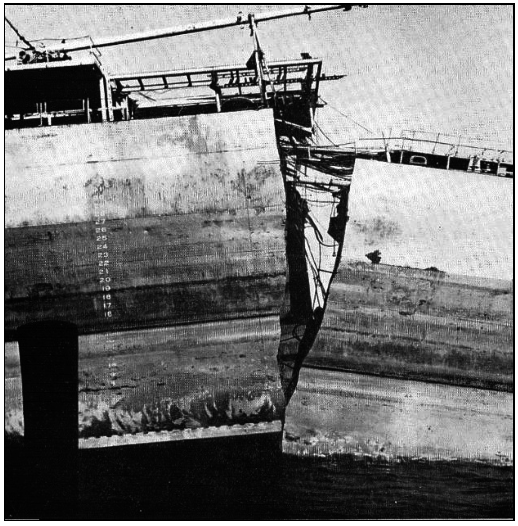
Figure 2.
(a) The geometry of surface and internal cracks; (b) Schematic stress profile of an internal crack (along the line X–X’ in (a)), demonstrating stress amplification at crack tip positions. Reproduced with permission from [3], Springer, 2009.
Figure 2.
(a) The geometry of surface and internal cracks; (b) Schematic stress profile of an internal crack (along the line X–X’ in (a)), demonstrating stress amplification at crack tip positions. Reproduced with permission from [3], Springer, 2009.

Figure 3.
Charpy-Impact Test arrangement and sample design. Reproduced with permission from [3], Springer, 2009.
Figure 3.
Charpy-Impact Test arrangement and sample design. Reproduced with permission from [3], Springer, 2009.

© 2016 by the author; licensee MDPI, Basel, Switzerland. This article is an open access article distributed under the terms and conditions of the Creative Commons Attribution (CC-BY) license (http://creativecommons.org/licenses/by/4.0/).
Share and Cite
MDPI and ACS Style
Zhang, W. Technical Problem Identification for the Failures of the Liberty Ships. Challenges 2016, 7, 20. https://doi.org/10.3390/challe7020020
AMA Style
Zhang W. Technical Problem Identification for the Failures of the Liberty Ships. Challenges. 2016; 7(2):20. https://doi.org/10.3390/challe7020020
Chicago/Turabian StyleZhang, Wei. 2016. "Technical Problem Identification for the Failures of the Liberty Ships" Challenges 7, no. 2: 20. https://doi.org/10.3390/challe7020020
Note that from the first issue of 2016, this journal uses article numbers instead of page numbers. See further details here.