Influences of Pile Group Effects on Wave Forces on an Offshore Bridge Pile-Cap Foundation


Department of Civil Engineering, Southwest Jiaotong University, Chengdu 610031, China
*
Author to whom correspondence should be addressed.
Challenges 2017, 8(2), 30; https://doi.org/10.3390/challe8020030
Submission received: 4 November 2017
/
Revised: 29 November 2017
/
Accepted: 30 November 2017
/
Published: 4 December 2017
Abstract
:In this study, a three-dimensional numerical model for a pile-cap system of an offshore bridge is developed to examine the pile group effect on wave force of pile with different arrangements of the pile group with a pile-cap system. In the present model, the Reynolds-averaged Navier-Stokes equation is taken as the governing equation for wave motion, while the volume of fluid method is used to trace the free water surface. Based on the present model, a set of analysis was conducted to examine the influence of the pile-cap system on the pile group effect, including the arrangement of the pile group, the submerged depth of the bridge cap, and the existence of the cap. Numerical examples show that the present model overall agreed well with the previous experimental data. The existence of the cap and submerged coefficient of the cap have a significant influence on the pile group effect coefficient. During the study of the pile group effect on the wave force of a pile with a pile-cap system of an offshore bridge, the influence of the existence of the cap on the pile group effect needs to be considered.
1. Introduction
In recent years, pile foundations have been commonly used in deep-water long-span offshore bridge construction due to their low cost, convenient construction, and structural efficiency [1,2,3]. The pile-cap system commonly found in these large-scale offshore bridge engineering environment is built by a group of piles with a large-scale cap on top of them. The pile-cap system mainly consists of a group of piles with different arrangements and a concrete cap connecting the piles. Most of the piles and caps are often submerged in the water, thus, the design of long-span offshore bridges need to consider the wave forces on piles with different arrangements of the pile-group and the existence of the large-scale cap.
The wave forces on a pile are significantly influenced by the arrangements of the pile-group, which is commonly divided into three kinds of basic arrangements according to the angle between the wave direction and the connecting line of the piles’ center, which includes tandem, stagger, and side-by-side. The method to investigate the pile group effect on the wave forces on the pile is usually classified in two ways the wave forces coefficient method and the wave forces method. The former method is based on the Morison equations [4]. Chakrabarti [5,6] investigated the drag and mass coefficients versus the Keulegan-Carpenter parameter through the wave tank test and presented a function to calculate the wave forces of the KC number and gap. Smith and Haritos [7,8] also proposed that the drag and inertia coefficients are a function of Keulegan-Carpenter parameter and the gap between the surface of two neighboring piles. The latter method was applied by Mindao et al. [9], Li et al. [10], and Bonakdar et al. [11,12]. Mindao et al. [9] proposed two equations to estimate the interference parameter and shelter parameter for the side-by-side and tandem arrangements of the pile group. Both of the parameters were expressed by the force ratio, which is the ratio of the wave forces on a slender pile in a pile group versus the wave forces on a single pile. It was found that the wave characteristics and water depth have no influence on the two parameters in the research conducted by [9]. Li et al. [10] introduced the significant pile group effect to evaluate the pile-group effect versus different KC parameters. They also found that the pile-group effect under the wave-current interaction condition was smaller than the wave only. Bonakdar et al. [11] proposed new formulae to estimate the pile-group effect parameter based on the M5Mt-GP model. They extended the research scope to the wave forces on the pile group under the breaking waves through a large number of small-scale laboratory tests [12].
All studies mentioned above were focused on the pile-group only, but the cap and pile are always simultaneously submerged in the water in a real offshore bridge environment. Due to the large-scale of the cap, the wave forces on the piles are significantly influenced by the cap thus, the pile-group effect must have a significant difference with the above studies. Hence, the study of the pile group effect on wave forces of the pile with the existence of a cap should have some useful references to the design and construction of the offshore bridge with the pile-cap system.
In this study, a three-dimensional numerical model for pile-cap system for an offshore bridge is developed to examine the pile group effect on wave force of pile with different arrangements of the pile group with pile-cap system. The detail size of the pile-cap system for the offshore bridge is referenced from the Ping-tan offshore bridge located on the east coast of China. In the present wave-structure model, the Reynolds-averaged Navier-Stokes equation combined with k-ε turbulence model are taken as the governing equation for wave simulation, while the volume of fluid (VOF) method is used to trace the free water surface. Compared with the previous studies, this paper has taken the influence of the pile-cap system on the wave field into account, because the forms of the pile-cap system have a significant effect on the pile group effect on the wave forces of pile. Most previous studies are limited to two dimensions, although three dimensions should be taken into consideration.
First, the feasibility and performance of the wave-structure interactions model is illustrated in the simulation of wave forces on piles with various pile group arrangements. The data obtained with the experiment and numerical simulation show that the wave-structure model works correctly in simulating the wave forces on the structure. Then, based on the present model, a set of analyses was conducted to examine the influence of the pile-cap system on the pile group effect, including the arrangement of the pile group, the submerged depth of the bridge cap, and the existence of the cap.
2. Theoretical Formulations
In this paper, the incompressible fluid motion due to the wave and pile-cap system interaction can be described by RANS equation, including mass conservation and momentum conservation equations.
The sketch of wave and pile-cap system interaction model is illustrated in Figure 1, where W = 14 m is the length of the cap, B = 7.7 m is width of the cap, h = 3 m is the height of the cap, D is the diameter of the pile, h1 is the submerged depth of the cap, d is the water depth of the numerical wave tank and submerged coefficient Cs = h1/h, a positive value of Cs implies that the cap are submerged in the water and a negative value of Cs implies that the caps are above the free water surface.
3. Wave Model
The wave is generated by adding a source function into the momentum conservation equation, and the incompressible water motion can be described by the RANS equations, mass conservation, and momentum conservation equations
in which xi is the Cartesian coordinate, ui and pi are the ensemble averaged velocity and the pressure of the fluid field, respectively. ρ is the fluid density, t is time, gi is the acceleration of gravity, and Si is a source term. τij is the stress tensor including the viscous stress and the Reynolds stress, which can be expressed by Equation (3)
in which ν is the dynamic viscosity, and ρ(u′iu′j) is the Reynolds stress term, which is modeled by the k-ε turbulent model [13,14]. By applying the eddy stress assumptions, the Reynolds stress term can be estimated by
where μt is the turbulence viscosity, k is the turbulence kinetic energy, δij is the Kroneker delta. Based on Equations (3) and (4), Equation (2) can be written as
where μeff = μ + μt is the total effective viscosity.
The k-ε turbulence model can be expressed as [13]
in which k is the turbulent kinetic energy and ε is the dissipation rate of turbulent kinetic energy. Cμ, σk, σε, Cε1, and Cε2 are constant values and these constant values in this model are calibrated by comprehensive data fittings for a wide range of turbulent flows [14]: Cμ = 0.09, σk = 1.00, σε = 1.30, Cε1 = 1.44, and Cε2 = 1.92.
In order to track the free water surface, the volume of fluid (VOF) method proposed by Hirt and Nichols [15] is used in this study. This method introduces a function F at the center of the cells to describe the fractional of the water fluid
where F = 1 or 0 represent a cell fully occupied by water or air, respectively. Hence, the free surface is the cell with values of 0 < F < 1.
The RANS equations were solved by the two-step method proposed by Bussmann et al. [16], discretization with the finite volume method (FVM). The computational domain is divided into a set of structure meshes.
4. Boundary Conditions
To solve the RANS equations, several approximate boundary conditions will be applied, which include the inlet boundary condition, outlet boundary condition, solid surface boundary condition, and the boundary condition at the free surface of water.
- (1)
- Inlet boundary condition: nonlinear wave is generated in the inlet boundary based on the source terms wave-maker method proposed by Choi and Yoon [17]. The wave propagates to the right of the computational domain.
- (2)
- Outlet boundary condition: A pressure outlet is given to the right of the computational domain. In order to make the wave propagate out of the outlet boundary without significant reflection and avoid interference with the current, a sponge layer was adopted before the outlet boundary with the width of a wavelength. The sponge layer method proposed by Wu [18] through adding the absorb function that was applied to the vertical velocity component to reduce the vertical velocities when the wave traveled into the sponge layer.
- (3)
- Boundary condition at the water surface: The actual pressure at the free surface of water should be equal to the atmospheric pressure and the relative pressure (p) at the free surface of water should be zero. The condition of zero surface tension as below should be satisfied
- (4)
- Solid surface boundary condition: At the bottom of the computational domain and the surface of the cap the no-slip boundary is adopted and the turbulence properties are obtained from the law of the wall boundary condition.
5. Convergence of the Mesh
Different size of meshes were tested to ensure the sensitivity and accuracy of the mesh solutions in simulating the wave and pile-cap system interaction problem. A set of mesh sizes was conducted by improving the mesh system until no significant changes in the simulation results. Figure 2 illustrates the maximum horizontal wave forces (FH* = FHmax/DρgH) on piles versus different mesh sizes (express by total numbers of mesh), in which FH* is the relative horizontal wave force and FHmax is the real maximum horizontal wave force. During this test, the water depth d = 30 m, wave height H = 2 m, wave period T = 6 s, and the diameter of the pile D = 1.8 m. The time-step in this manuscript is 0.01 s. As shown in Figure 2, the mesh sizes adopted in this study are feasible enough to satisfy the computational accuracy.
6. Model Validation
In this section, the RANS model will be validated by comparing with the previous experimental data [12] available in the literature.
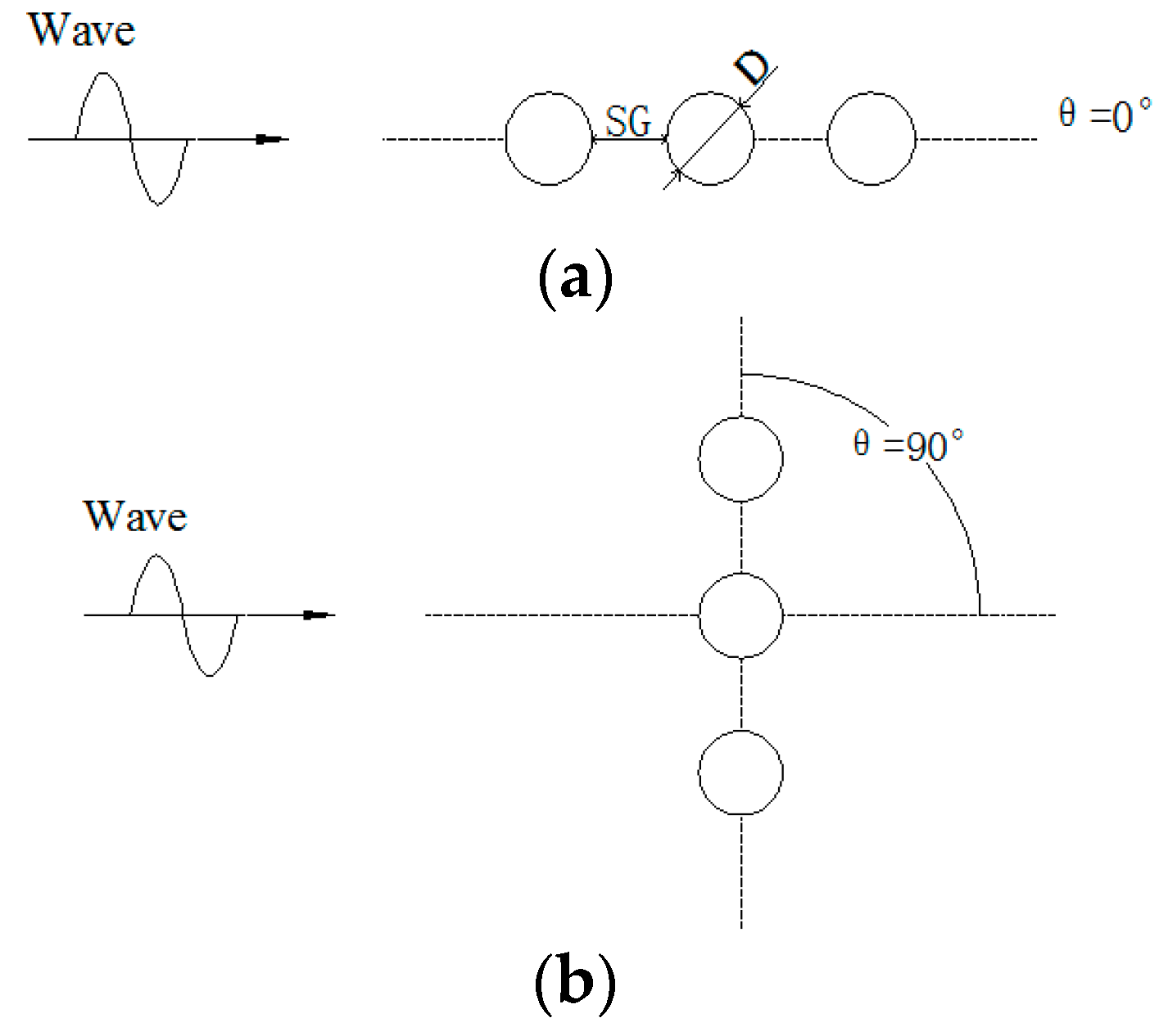
The validation is to compare the model with laboratory experimental data [12] for the case without the cap under wave forces. In the experiment, the force and moment transducers were used to measure the wave force and wave moment on the measured pile, which is 5 cm in diameter. The line force was measured by a ring transducer at a certain elevation of water (z/h = 0.78). An acoustic Doppler velocimeter was used to capture the wave-induced horizontal flow velocity at this certain elevation. In this paper, two kinds of pile group arrangements, including side-by-side and tandem, were selected to make a comparison and the sketch of the two kinds of arrangements is illustrated in Figure 3. The KC number KC = umaxT/D, where umax is the maximum horizontal wave-induced flow velocity at a certain elevation of water (z/h = 0.78), T is the wave period, and D is the diameter of the pile. The pile group effect was evaluated by the pile-group effect coefficient KG = fGroup/fSingle, where fGroup are the line forces on the pile with a group of piles measured by the ring transducer, and the fSingle is the wave force on a single pile under the same wave conditions. The detailed explanation of the laboratory experiment can be seen in Bonakdar et al. [12].
The numerical simulation domain used to compare with the laboratory experiment has a length of 10 m, a width of 5 m, and a height of 1 m. The sponge layer is placed at the last 2 m in the computational domain. The mesh size used in this model is Δx = 0.002 m and Δy = 0.001 m. The pile group was placed at the middle of the wave tank. The wave conditions used in the numerical simulations were same as the laboratory experiment. Figure 4 and Figure 5 show the relationship between the pile group effect KG and KC number for side-by-side and tandem arrangements with SG/D = 1, respectively, where SG represents the gap between the surface of two neighboring piles. Both of the figures show good agreement between the numerical simulation and laboratory experimental data. It can be concluded from the comparison that the present model can provide a sufficient accreted prediction of wave forces on structures.
7. Model Validation Results and Discussions
In this section, the present model will be applied to examine the pile group effect under the wave and pile-cap system interaction with different arrangements of the pile group, SG/D numbers, and submerged coefficients.
The parameters used in the following numerical examples are listed in Table 1 unless they are specified in detail.
8. Pile Group Effect for the Existence of a Cap
It is expected that the existence of the cap can affect the wave-induced forces on the pile through changing the flow conditions around the connecting part between the cap and pile. Therefore, it is essential to give a particular comparison to explain the influence of the cap on the wave-induced forces on the pile.
Figure 6 and Figure 7 illustrate the distributions of the flow velocity field around the pile without the cap and the connection part between the cap and pile, respectively. Here, wave height H = 2 m, wave period T = 6 s, and the submerged coefficient Cs = 1 and SG/D = 1.
As is shown in Figure 6 and Figure 7 the existence of the cap significantly influenced the flow velocity field around the connection part between the cap and pile. Furthermore, due to the complex geometry of the cap, the velocity fields around the connection part changed unpredictably. Thus, the wave forces on the pile with a cap must have a significant difference from that of the pile without a cap.
A set of numerical simulations was conducted to evaluate the variation of the pile group effect for the pile-cap system under different kinds of arrangements of pile group versus various KC numbers. The pile group effect was evaluated by the pile-group effect coefficient KG = fGroup/fSingle, where fGroup are the forces on the pile with a group of piles, and the fSingle is the wave force on a single pile under the same wave conditions. The KC number KC = umaxT/D, where umax is the maximum horizontal wave-induced flow velocity calculated at an elevation of the water surface, T is the wave period, and D is the diameter of the pile. Two different kinds of pile group arrangements, including side-by-side and tandem, were used in this section.
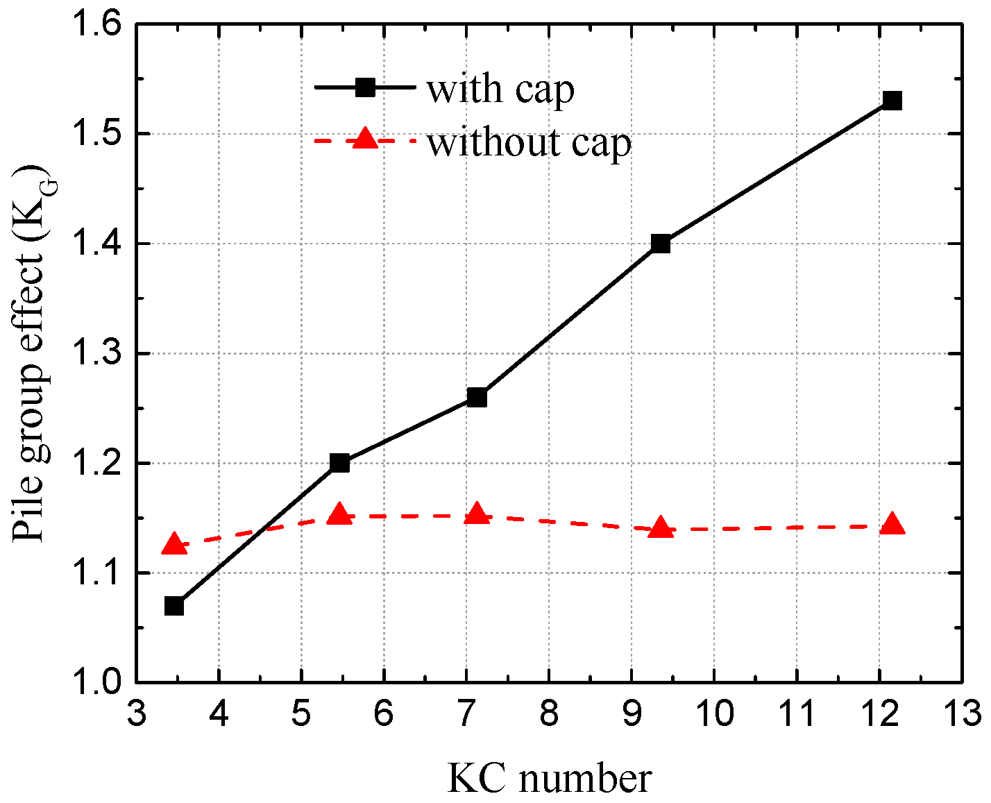
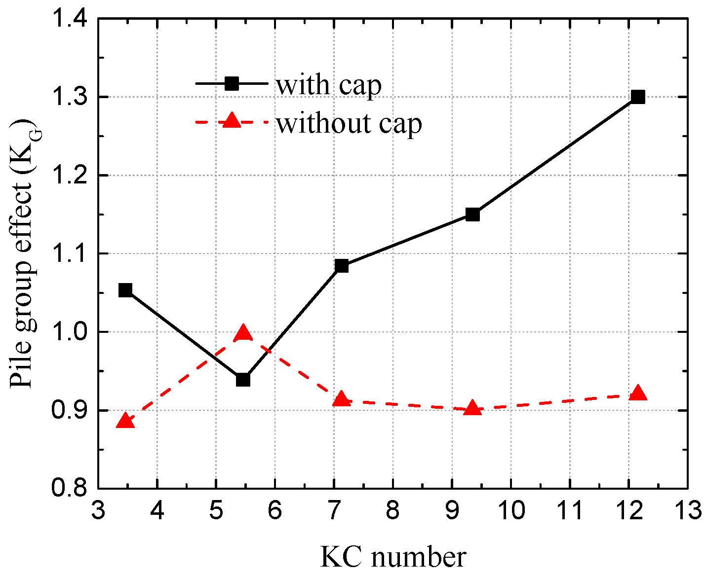
Figure 8 and Figure 9 illustrate the variations of the pile group effect versus various KC numbers with side-by-side and tandem arrangements of the pile group, respectively. In the situation of the tandem arrangement of the pile group, there are two pile supporting the cap, while the side-by-side arrangement has three piles. The measured pile is the middle one in the side-by-side arrangement and the last one in the tandem arrangement of the pile group. The detailed wave parameters are listed in Table 2 for the five cases. Here, SG/D = 1.
From both of the figures, we have concluded that the existence of a cap has a great influence on the pile group effect coefficient, which also means that the cap brings a very large change in the flow regime around the pile group. Figure 8 shows that with the increase of the KC number, the pile group effect coefficient KG increases with the existence of the cap. Without the cap, the pile group effect coefficient KG remains nearly unchanged versus different KC numbers. The smallest value of the pile group effect when the KC number is equal to 5.5 possibly caused by the ratio of the structure size and the wave length. Figure 9 illustrates that the pile group effect coefficient KG first decreases and then increases with the increment of the KC number, which has a large difference with the situations than without the cap. This is because the presses area of the group piles’ foundation with a cap is much larger than that without a cap, which make the wave forces on the group piles’ foundation with a cap larger than that without a cap. Thus, during the study the pile group effect on the wave force of the pile with a pile-cap system of an offshore bridge, the influence of the existence of the cap on the pile group effect needs to be considered.
9. Pile Group Effect for Different Submerged Depths of the Cap
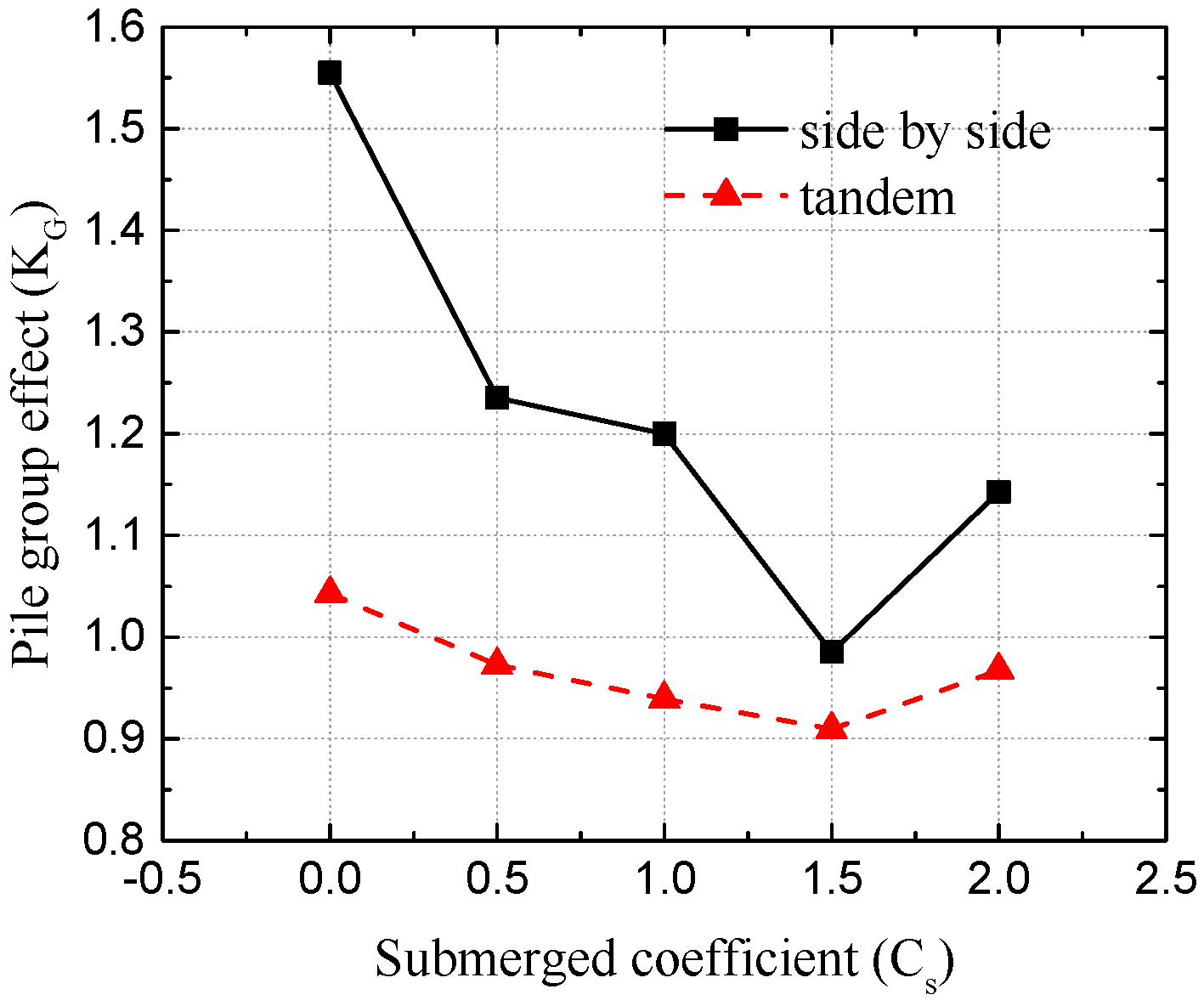
In this section, five types of submerged coefficients of the cap from 0 to 2, with an interval of 0.5, were selected to evaluate the variations of the pile group effect with the side-by-side arrangement. Here, wave height H = 3 m, wave period T = 8 s, water depth d = 30 m, and SG/D = 1. Figure 10 illustrates the variations of the pile group effect versus various submerged coefficients of the cap with different arrangements of the pile group.
It is easily concluded from Figure 10 that the tendency of the change of the pile group effect is similar between the side-by-side and tandem arrangements of the pile group versus different submerged coefficients of the cap. The pile group effects are more sensitive to the side-by-side arrangement than the tandem arrangement. This is because the presses area of the side-by-side arrangement is much larger than that the tandem arrangement. Another observation from Figure 10 is that the difference of the pile group effects between the pile group foundation with a cap and the pile group foundation without a cap decreases with the increment of the submerged coefficient.
Based on the numerical results, the tandem arrangement is suggested in engineering practice, since the wave forces on the side-by-side arrangement is much larger than that on the tandem arrangement.
10. Conclusions
In this paper, a three-dimensional wave-structure interaction numerical model is established to explore the pile group effect on the wave force of a pile with different arrangements of the pile group under various KC numbers, and the influence of the existence of the cap on the pile group effect was also discussed. Based on the investigations, we conclude:
- (1)
- As shown in the validations, the proposed model agrees well overall with previous experimental data under the same wave conditions;
- (2)
- The velocity fields around the pile have a significant change with the existence of the cap. Due to the complex geometry of the cap, the velocity field around the cap between the pile and the pile-cap system are quite different. Thus, the investigation of wave forces on the pile with a cap is meaningful for offshore bridge engineers to design the bridge with the pile-cap system;
- (3)
- The existence of the cap has a significant influence on the pile group effect coefficient, during the study of the pile group effect on the wave force of the pile with a pile-cap system of an offshore bridge, the influence of the existence of the cap on the pile group effect needs to be considered;
- (4)
- The side-by-side arrangement is more sensitive to the submerged coefficient of the cap than the tandem arrangement.
Acknowledgments
The first author is grateful for the support from the National Natural Science Foundation of China (51178397) and the Scholarship from Southwest Jiaotong University Scholarship Council.
Author Contributions
Baoshan Xiang and Bo Huang conceived and designed the numerical model; Bo Huang and Zhiying Yang performed the numerical model; Baoshan Xiang and Bing Zhu analyzed the data; Ruitao Yin contributed analysis tools; Baoshan Xiang wrote the paper.
Conflicts of Interest
The authors declare no conflict of interest.
References
- AbdelSalam, S.S.; Sritharan, S.; Suleiman, M.T. Hydrodynamic coefficients for a vertical tube in an array. J. Bridge Eng. 2010, 15, 749–758. [Google Scholar] [CrossRef]
- DiMaggio, J.A.; Goble, G.G. Developments in deep foundation highway practice—The last quarter century. In Current Practices and Future Trends in Deep Foundations; DiMaggio, J.A., Hussein, M.H., Eds.; ASCE: Reston, VA, USA, 2004; pp. 110–127. [Google Scholar]
- Wei, K.; Yuan, W.; Bouaanani, N. Experimental and numerical assessment of the three-dimensional modal dynamic response of bridge pile foundations submerged in water. J. Bridge Eng. 2013, 18, 1032–1041. [Google Scholar] [CrossRef]
- Morison, J.R.; O’Brien, M.P.; Johnson, J.W.; Schaaf, S.A. The force exerted by surface waves on piles. J. Pet. Technol. 1950, 2, 149–154. [Google Scholar] [CrossRef]
- Chakrabarti, S.K. Hydrodynamic coefficients for a vertical tube in an array. Appl. Ocean Res. 1981, 3, 2–12. [Google Scholar] [CrossRef]
- Chakrabarti, S.K. Inline and transverse forces on a tube array in tandem with waves. Appl. Ocean Res. 1982, 4, 25–32. [Google Scholar] [CrossRef]
- Smith, D.; Haritos, N. The effect of in-line spacing of two cylinder groups on the morison force coefficients. In Proceedings of the 15th International Conference on Offshore Mechanics and Arctic Engineering (OMAE), Florence, Italy, 16–20 June 1996. [Google Scholar]
- Smith, D.; Haritos, N. The influence of grouping on the force characteristics of pairs of vertical surface-piercing cylinders. In Proceedings of the 7th International Offshore and Polar Engineering Conference, Honolulu, HI, USA, 25–30 May 1997. [Google Scholar]
- Mindao, G.; Lihua, H.; Shaoshu, S. Experimental study for the wave forces on pile groups due to regular waves. In Proceedings of the 2nd International Conference on Coastal and Port Engineering in Developing Countries (COPEDEC), Beijing, China, 7–11 September 1987; pp. 1956–1965. [Google Scholar]
- Li, Y.C.; Wang, F.L.; Wang, H.R. Wave-current forces on vertical piles in side-by-side arrangement. In Proceedings of the 3rd International Offshore and Polar Engineering Conference (ISOPE), Singapore, 6–11 June 1993. [Google Scholar]
- Bonakdar, L.; Oumeraci, H.; Etemad-Shahidi, A. Wave load formulae for prediction of wave-induced forces on a slender pile within pile groups. Ocean Eng. 2015, 102, 49–68. [Google Scholar] [CrossRef]
- Bonakdar, L.; Oumeraci, H. Pile group effect on the wave loading of a slender pile: A small-scale model study. Ocean Eng. 2015, 108, 449–461. [Google Scholar] [CrossRef]
- Launder, B.E.; Spalding, D.B. The numerical computation of turbulence flows. Comput. Methods Appl. Mech. Eng. 1974, 3, 269–289. [Google Scholar] [CrossRef]
- Rodi, W. Turbulence Models and Their Application in Hydraulics-State-of-the-Art Review, 3rd ed.; Balkema: Rotterdam, The Netherlands, 1993. [Google Scholar]
- Hirt, C.W.; Nichols, B.D. Volume of fluid (VOF) method for the dynamics of free boundaries. J. Comput. Phys. 1981, 39, 201–225. [Google Scholar] [CrossRef]
- Bussmann, M.; Mostaghimi, J.; Kirk, D.W.; Graydon, J.W. A numerical study of steady flow and temperature fields within a melt spinning puddle. Int. J. Heat Mass Transf. 2002, 45, 3997–4010. [Google Scholar] [CrossRef]
- Choi, J.; Yoon, S.B. Numerical simulations using momentum source wave-maker applied to RANS equation model. Coast. Eng. 2009, 56, 1043–1060. [Google Scholar] [CrossRef]
- Wu, T.R. A Numerical Study of Three-Dimensional Breaking Waves and Turbulence Effects. Ph.D. Thesis, Cornell University, New York, NY, USA, 2004. [Google Scholar]
Figure 1.
Sketch of the wave and pile-cap system interaction.
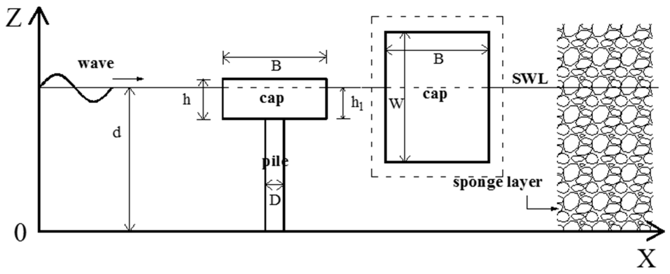
Figure 2.
Variations of wave-induced maximum horizontal forces (FH* = FHmax/DρgH) on piles for different mesh numbers.
Figure 2.
Variations of wave-induced maximum horizontal forces (FH* = FHmax/DρgH) on piles for different mesh numbers.
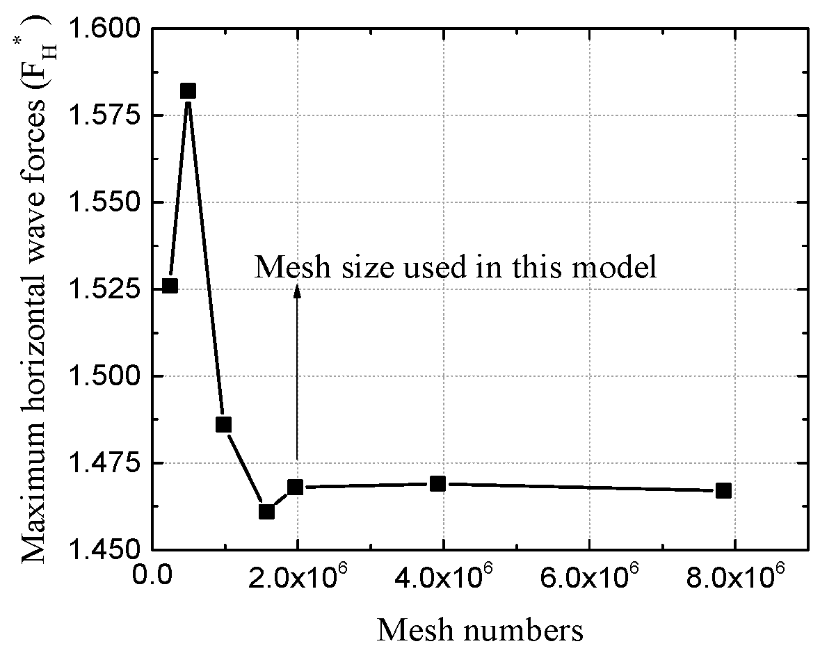
Figure 3.
Sketch of the pile group arrangements: (a) side-by-side; (b) tandem.

Figure 4.
Variations of the pile group effect KG versus different KC numbers for the side-by-side arrangement with SG/D = 1.
Figure 4.
Variations of the pile group effect KG versus different KC numbers for the side-by-side arrangement with SG/D = 1.
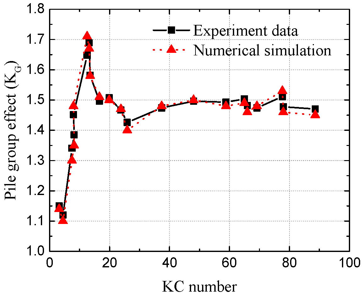
Figure 5.
Variations of the pile group effect KG versus different KC numbers for the tandem arrangement with SG/D = 1.
Figure 5.
Variations of the pile group effect KG versus different KC numbers for the tandem arrangement with SG/D = 1.
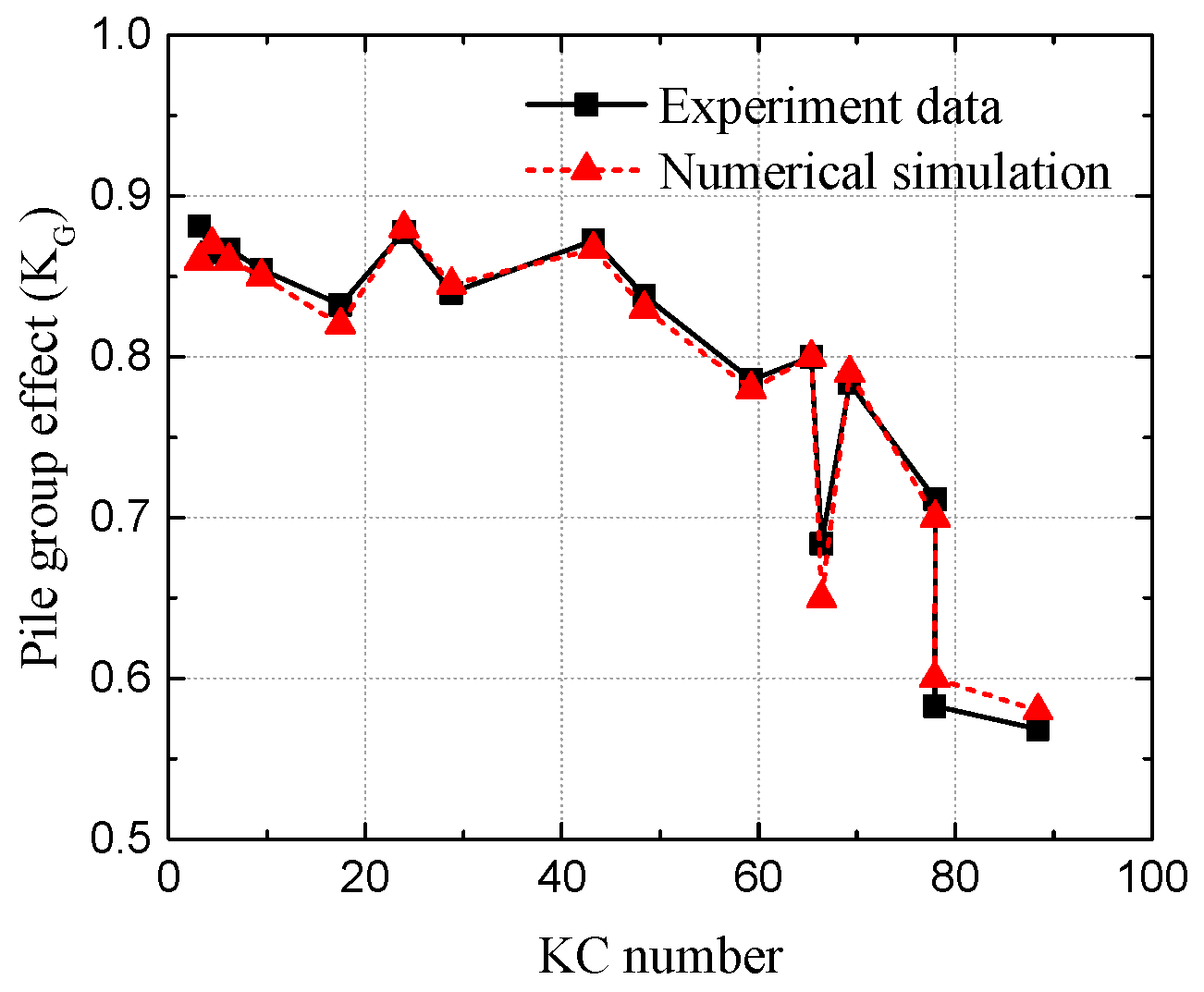
Figure 6.
Variations of the flow velocity around the pile without cap.
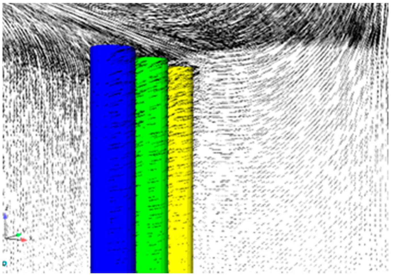
Figure 7.
Variations of the flow velocity around the connection part between the cap and pile.

Figure 8.
Variations of the pile group effect versus various KC numbers with the side-by-side arrangement of the pile group.
Figure 8.
Variations of the pile group effect versus various KC numbers with the side-by-side arrangement of the pile group.

Figure 9.
Variations of the pile group effect versus various KC numbers with the tandem arrangement of the pile group.
Figure 9.
Variations of the pile group effect versus various KC numbers with the tandem arrangement of the pile group.

Figure 10.
Variations of the pile group effect versus various submerged coefficients of the cap with different arrangements of the pile group.
Figure 10.
Variations of the pile group effect versus various submerged coefficients of the cap with different arrangements of the pile group.

Table 1.
Input parameters of numerical examples.
| Structural Characteristics | |
| Pile diameter (m) | 1.8 |
| Length of cap (m) | 14 |
| Width of cap (m) | 7.7 |
| Height of cap (m) | 3 |
| Wave Characteristics | |
| Wave height (m) | 2–4.5 |
| Wave period (s) | 6–14 |
| Water depth (m) | 30 |
| Submerged coefficient | 0–2 |
Table 2.
Input parameters of five numerical cases.
| Case No | Wave Height (m) | Wave Period (T) | KC Number |
|---|---|---|---|
| 1 | 2 | 6 | 3.46 |
| 2 | 3 | 8 | 5.46 |
| 3 | 3.5 | 10 | 7.13 |
| 4 | 4 | 12 | 9.35 |
| 5 | 4.5 | 14 | 12.16 |
© 2017 by the authors. Licensee MDPI, Basel, Switzerland. This article is an open access article distributed under the terms and conditions of the Creative Commons Attribution (CC BY) license (http://creativecommons.org/licenses/by/4.0/).
Share and Cite
MDPI and ACS Style
Xiang, B.; Huang, B.; Yang, Z.; Zhu, B.; Yin, R. Influences of Pile Group Effects on Wave Forces on an Offshore Bridge Pile-Cap Foundation. Challenges 2017, 8, 30. https://doi.org/10.3390/challe8020030
AMA Style
Xiang B, Huang B, Yang Z, Zhu B, Yin R. Influences of Pile Group Effects on Wave Forces on an Offshore Bridge Pile-Cap Foundation. Challenges. 2017; 8(2):30. https://doi.org/10.3390/challe8020030
Chicago/Turabian StyleXiang, Baoshan, Bo Huang, Zhiying Yang, Bing Zhu, and Ruitao Yin. 2017. "Influences of Pile Group Effects on Wave Forces on an Offshore Bridge Pile-Cap Foundation" Challenges 8, no. 2: 30. https://doi.org/10.3390/challe8020030
Note that from the first issue of 2016, this journal uses article numbers instead of page numbers. See further details here.