Performance Study of Adaptive Video Streaming in an Interference Scenario of Femto-Macro Cell Networks


1
Department of Computer Science & Engineering, University of Kurdistan-Hawler, Erbil 44001, Iraq
2
Department of Engineering Sciences, Faculty of Engineering, Istanbul University, Istanbul 34452, Turkey
*
Author to whom correspondence should be addressed.
Information 2018, 9(1), 22; https://doi.org/10.3390/info9010022
Submission received: 27 November 2017
/
Revised: 14 January 2018
/
Accepted: 16 January 2018
/
Published: 18 January 2018
(This article belongs to the Special Issue Selected Papers from WMNC 2017 and JITEL 2017)
Abstract
:The demand for video traffic is increasing over mobile networks that are taking another shape by its heterogeneity. However, the wireless link capacity cannot cope with the traffic demand. This is due to the interference problem that can be considered as the most important challenge in heterogeneous networks. Consequently, it will result in poor service for the quality of video streaming such as the bad quality delivery, service interruption, etc. In this paper, we propose a solution for interference mitigation in the context of heterogeneous networks through power control mechanism, while guaranteeing the Quality of Service of the video streaming. We derive a model for adapting the video bit rate to match the channel’s achievable bit rate. Our results demonstrate a high satisfaction for video streaming in terms of delay and throughput.
1. Introduction
Networks of the future will be heterogeneous as they will shape the landscape of the wireless environment through offering different kinds of services like data rates, Quality of Service (QoS) capabilities and mobility. Such kind of network is introduced in Long-Term Evolution Advanced (LTE-A). The reason behind introducing Heterogeneous Networks (HetNet) LTE-A is to cope with the increasing number of mobile broadband data subscribers and bandwidth-intensive services competing for limited radio resources in 5G networks [1]. Since the sole macrocell cannot meet the requirements of mobile users in terms of QoS, HetNet architecture consists of different types of Radio Access Networks (RANs) or cells: a collocated macrocell, picocells, femtocells and relay nodes. In our case, we focus on the integration of femtocells and macrocells as a case study. However, in the scenario when the Macrocell Base Station (MBS) and Femtocell Base Station (FBS) use the same spectrum, a cross-tier interference will occur and will cause a severe interference to the Macrocell User Equipment (MUEs). especially when they are not registered with the operator of the FBS. The major issue that should be considered is how to mitigate the interference in a scenario when FBSs use the Close Subscriber Group (CSG) for Femtocell User Equipments (FUEs) and cause a severe interference to MUEs, leading to a bad quality of Signal-to-Interference Noise Ratio (SINR) received by the MUEs [2]. The Downlink (DL) direction of LTE specifications uses an Orthogonal Frequency Division Multiple Access (OFDMA) modulation technique where the basic unit of resource allocation is called Resource Block (RB), and it is assigned by the scheduler every 1 ms [3]. The bad quality of the SINR affects the QoS of the different ongoing applications regardless of their type in HetNet scenario. However, in this article, we are more focused on the Video Streaming application as an example of an application suffering from bad channel quality caused by interference. We selected the video streaming because it has a special character that overcomes the problem of interference by Scalable Video Coding (SVC) technique, which is the Annex G extension of the H.264/MPEG-4 AVC video compression standard. It implements the bit rate adaptivity. It encodes the raw video clip into a base layer and a number of enhancement layers with different priorities. Naturally, the base layer has the highest priority since it contains the video bits with the highest importance, which can provide a minimum video quality. The enhancement layers with lower priorities may be progressively encoded to further refine the quality of the base-layer stream. Scalable video coding and adaptive streaming techniques can be jointly combined to accomplish effectively the best possible quality of video streaming services. Hence, we can dynamically adjust the number of SVC layers depending on the current link status.
However, before using any mechanism of adaptation between video rate and link status, it is important to know the link status that is playing a great role for delivering a good quality video service. Since, in our context, the user channel is experiencing an interference, it should be mitigated. Once the quality of channel is known, the rate of the video should be adapted to it.
In this article, we propose a complete framework of HetNet Integration between macrocell and femtocells. Since such integration raises the challenge of interference, we then suggest a solution based on power adjustment in order to mitigate interference. A solution is suggested based on a distributed Power Allocation (PA) method to reduce the cross-tier interference caused to the MUEs by the FBSs. Firstly, we classify the interfering femtocells into clusters depending on the Received Signal Strengths (RSSs) reports that are sent periodically by MUEs on the Uplink (UL) transmission. This will help each FBS to identify the average number of MUE victims of interference. Whenever this number becomes statistically greater than those of the neighbors that are interfering femtocells, the FBS is then instructed directly from the MBS to adjust its transmitted power. Conversely, the FBSs work independently to decrease their transmitted power by using the RSSs report sent by the closest MUEs. In the first case, the FBS is instructed centrally by the MBS; however, in the second case, the FBS works autonomously and in a distributed way for adjusting their transmission power. Upon mitigating interference and in order to test our solution, we initiate video streaming applications through the MUEs and FUEs in order to investigate the effect of our power adjustment on the QoS of this application.
This article is organized as follows: starting with the main assumptions of the system model in Section 3, the proposed power adjustment scheme is presented in Section 4. This is followed by introducing the adaptive method of rate matching in Section 5 and the simulation environment is defined and results are presented in Section 6. Conclusions are presented in Section 7.
2. Related Work
According to the Cisco Visual Networking Index, a video will continue to dominate IP traffic and overall Internet traffic growth—representing 80% of all Internet traffic by 2021, up from 67% in 2016 [4]. Many research works investigated characteristics of video streaming and its ability to be adapted to channel variation nature, especially in the context of interference. However, no significant attention has been given to tackle the context of HetNet and investigate the behaviour of video streaming when interference occurs. An adaptive video streaming architecture was proposed together with a resource allocation framework in [5]. However, the main aim of the paper was to improve the Quality of Experience (QoE) with handling the resource allocation problem with Integer Linear Programming (ILP) formulation.
An energy-video aware multipath transport protocol (EVIS) for HetNet has been proposed and a mathematical model developed to analyse the energy per frames for multi-homed video communication over multiple communication paths in [6]. They also developed scheduling algorithms for prioritized frame scheduling and unequal loss protection to achieve target video quality with minimum device energy consumption, showing that EVIS has a significant improvement in energy conservation, video peak signal-to-noise ratio (PSNR), end-to-end delay, and goodput compared to other works in the literature.
Real-time video traffic splitting strategies were introduced for heterogeneous wireless networks composed of WiFi and cellular networks to maximize the needed energy consumption with reducing delay, solutions were presented for resource management in [7]. Lyapunov drift-plus-penalty optimization was utilized for cellular/WiFi network over a test bed implementation.
The development of an energy-efficient bandwidth aggregation scheme for video transmission over wireless channel has been addressed as another challenging issue [8] . For this, an Energy-quaLity aware Bandwidth Aggregation (ELBA) scheme is introduced integrating energy-minimized rate adaptation, delay-constrained unequal protection, and quality-aware packet distribution. The method could minimize energy with regards to the quality of video streaming within imposed deadlines. Video distortion in the decision process of a multipath data transfer is introduced and a distortion-aware concurrent multipath transfer (CMT-DA) solution has been proposed to analytically formulate the data distribution over multiple communication paths to minimize the end-to-end video distortion and derive the solution based on the utility maximization theory [9].
In order to prevent freezes at the clients, a network-based framework was introduced where a network controller prioritizes the transmission of specific video segments. Furthermore, a Machine Learning (ML) engine based framework was elaborated and, under various video streaming scenarios, an ML-based framework’s performance was compared with many HTTP Adaptive Streaming (HAS) based solutions [10]. For video streaming, Dynamic Adaptive Streaming over HTTP was used in both wired and wireless environments, but video quality oscillation and video freeze in wireless environments cause poor user experience. The Wireless Quality Adaptation (WQUAD) algorithm was developed to provide stable performance [11]. The presented algorithm eliminated bandwidth estimation from quality adaptation and provided video freeze prevention and high video quality on average. For each Dynamic Adaptive Streaming over Hypertext Transfer Protocol (HTTP) (DASH) user, a wireless resources allocating scheduler was presented. The scheduler worked with the QoE-aware cross-layer and improved the video quality [12].
Authors in [13] introduced an extensive review of HAS techniques across multimedia and networking domains. They addressed the major issue that the users can perceive from the multimedia streaming, which is the QoE, along with the challenges that influence the QoS just like the variation of channel condition, which is normally ignored by the HAS technologies. As the number of users increases, it is hard to satisfy their needs in terms of throughput. This is why authors in [14] proposed a Software Defined Network (SDN)-based Transmission Control Protocol (TCP) throughput management algorithm to provide fairness to competing users over a wireless network. The main ideas are to avoid oscillation of the video quality and stable buffer length. Authors showed significant improvement of fairness among users.
A playback length changeable 3D video data chunk segmentation (PLC3DCS) algorithm and a hybrid-priority based 3D video P2P data scheduling algorithm were presented for heterogeneous networks. Bandwidth-adaptive 3D video P2P streaming was applied to gain better error-resilience and network utilization performance with improving the chunks’ success delivery rates [15]. A high-quality video streaming technique was proposed [16]. The presented technique provides remotely formed content to be gained and streamed to multi-tile display environments on a heterogeneous wide area network. To minimize the entropy and needed bandwidth of the video stream, video compression was used. Thus, 1080p resolution and multimedia rich content with bandwidth requirements below 10 Mbps was delivered. A QoS supporting video streaming system over heterogeneous wireless networks was presented and the system was tested on real Wireless Local Area Network(WLAN) and LTE networks [17]. Fountain code was utilized to decrease errors and losses on unstable wireless network with consolidating many physical paths in a cost-effective way. An adaptive multi-interface selection video streaming system was proposed with a prototype that was improved on iOS (iPhone 5s) over LTE and WiFi network in [18]. Basically, the system was composed of a reliable cloud-based video delivery scheme together with the split-layer SVC encoding and real-time adaptive multi-interface selection. The system was tested in various real-world networks about improving the video quality.
Video streaming to mobile devices is an example of content-on-the-move, which has gained a great increase in volume together with multimedia traffic in recent years. Thus, research on video streaming presents remarkable progress. In 2013, 53% of the global mobile Internet traffic was composed of video content delivery. Furthermore, by 2018, it is expected to reach 67% of the global mobile Internet traffic [19]. A distributed and adaptive resource management controller that allows the optimal exploitation of Cognitive Radio and soft-input/soft-output data fusion in Vehicular Access Networks has been designed and the problem of resource management through the use of stochastic network utility maximization for reducing the energy of the vehicular nodes through offloading traffic towards the cloud has been solved [20].
For variable available transmission capacities presenting multicasting video, SVC technology was proposed as a remarkable mechanism. For real-time dissemination of video, wireless video multicasting was proposed as an effective solution. Wireless video multicasting utilizes its own broadcast structure and SVC is a good solution for the heterogeneity problem of networks. One base layer and many higher layers form the SVC-encoded video stream. Video’s main quality is given by the base layer. More than one higher layer presents identical video with rising qualities. On the transmitting side, variable Modulation and Coding Schemes (MCSs) are implemented on variable video layers. Thus, a subset of layers is received that is available for channel conditions [21].
Lately, high-definition video data utilization in cellular networks has risen because of the ever increasing high-end smart phone usage. To be able to provide the best device capabilities, mobile service providers work on presenting high-quality video service in a bandwidth-efficient manner. For LTE broadcast/evolved multimedia broadcast multicast service and terrestrial broadcast TV/ATSC 3.0 services, an open-loop multi-input multioutput (MIMO) scheme was proposed with considering the SVC. A well known video compression technique SVC supports simulcasting. A high-quality video sequence is divided by SVC into bit-stream layers. Thus, a better service degradation will be decoded under variable reception scenarios. These scenarios may be H.264/SVC and H.265/SHVC. In SVC, the QoS is based on the highest enhancement layer, which will be mainly processed. The main aim of the presented scheme was to provide the minimum vital information together with gaining additional information to develop the quality of video [22].
In this work, we propose to (i) mitigate significant interference for MUE victims in a HetNet scenario where its SINR is unsatisfied; (ii) to match the data rate of the interfered channel with the video rate in a way that the best quality video service is delivered by an adaptive resource allocation scheme; and (iii) to allocate RBs in an optimized way to deliver higher QoS (Table 1 describes all the acronyms used in the article).
3. System Model and Assumptions
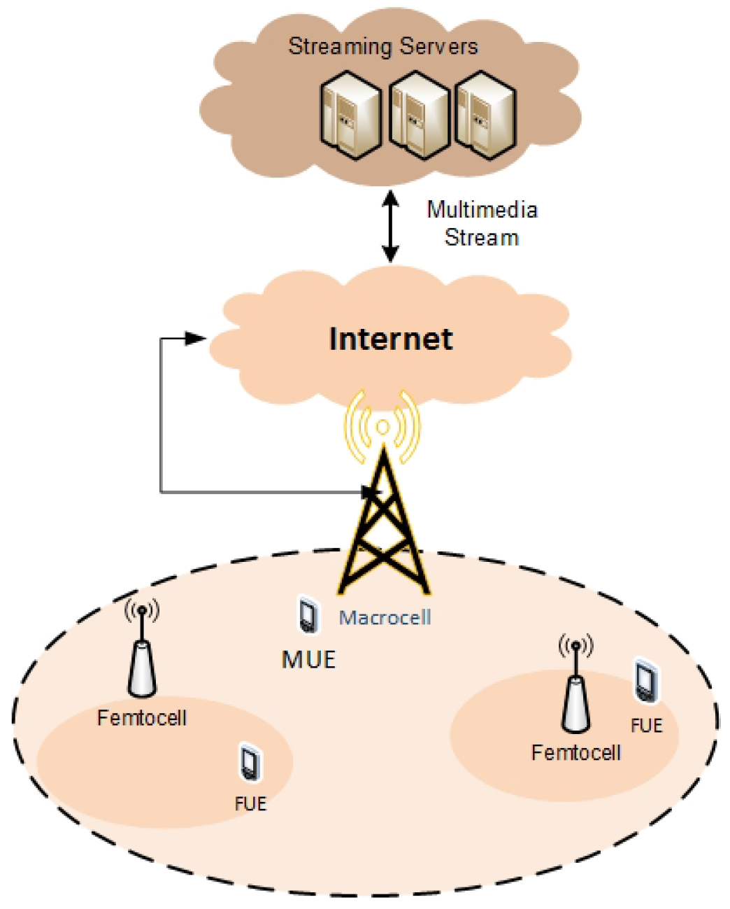
Our system model is represented by video streaming over HetNet. The HetNet is mainly composed of two components; macrocells and femtocells (cf. Figure 1), where the former provides mobility capability while the latter tries to extend coverage and capacity. The mobile device can be connected to the HetNet first, then the Internet, and finally the cloud computing where video streaming services are located. We assume a centralized Mobile Cloud Computing paradigm as it is the most conventional. The macrocell is controlled by the MBS, which is responsible for regulating traffic in the macrocell, while the small cells are operated by FBSs. Here, a distinction between user equipment, which is connected to MBS as they are called MUEs or Macrocell User Equipment, and the users who are connected to small cells, which are called FUEs or Small User Equipment, is essential [23].
Video streaming over wireless networks faces many challenges due to the nature of the wireless channel, which is time varying and has limited resources in terms of bandwidth, making it hard to guarantee any specific video QoS. However, when considering the context of HetNet, the main problem can be represented by the interference, which influences the quality of video delivered by the network (Table 2 describes all the symbols used in the article with their meaning).
In this structure, I MUEs are uniformly distributed within the MBS coverage area and they are not allowed to access femtocell during their mobile tour, i.e., all the outdoor users are non-CSG users for operators. An covers J randomly distributed FUEs. The MUEs and FUEs use a common frequency band divided into k RBs with OFDMA-based transmissions. We also assume that the macrocell M is full up and cannot provide any intra-channel allocation to mitigate the probable interference caused to MUEs users. Both M and FBSs need a periodical report as Channel Quality Indicator (CQI). in terms of SINR to check the signal quality of their UEs and provide the resource allocation of their RBs. The receiver DL SINR of a given related with M on resource block k can be defined as:
where is the present transmit power allocated on RB k by the serving cell M, and is the channel gain between and its macrocell M on RB k. In the same way, is the transmit power of neighboring femtocell on RB k. is the white noise power spectral density and represents the set of all interfering FBSs on on RB k. is the channel gain between the and the neighboring on RB k.
In general, the average channel between the transmitter (T) represented by and the receiver (R) represented by is formulated as follows:
where is the path loss exponent with the distance between T and R, and are the shadowing and fast fading components, respectively, and is a factor related to speed of users. Using preambles in several RBs by the MUEs assist in knowing the average by the serving cell M and all neighboring Fs. This means that Fs can capture this information according to report sent back by the MUEs during uplink transmission. We suppose that M knows the on each RBs k, as well as the from an according to some conditions detailed in the following sections. Consequently, the Fs can detect also a whether it is in the neighborhood or not by receiving the ’s report, which includes the from the UL transmission. At the same time, we assume that the average channel gain from an to a neighboring is the same as that was sent from an to . Since the path loss and shadowing components are the same, then the channel gain is known easily from an even though this possibility is not used neither in Frequency Division Duplex (FDD) nor in Time Division Duplex (TDD) system [24], while the on a specific RB k can be calculated directly when the is known from a neighboring .
4. A Hybrid Algorithm for Power Allocation in Macrocell/Femtocell Architecture
Giving the fact that all the femtocells are deployed within the umbrella of the macrocell using a full frequency reuse scheme, the transmission signal from FBSs will cause a strong interference to neighboring MUEs, leading to a large degradation of their received . The aim of the femtocell power adjustment is to maximize the sum of the macrocell and femtocells’ throughputs, while satisfying both MUEs’ and FUEs’ SINR requirements.
In order to proceed, we propose an algorithm to achieve the above-mentioned objective through the following steps: (i) defining clusters according to the geographical locations of interfering Fs; (ii) dividing clusters into sub clusters of Master/Slave-Fs; (iii) applying centralized power allocation in Master-Fs clusters; and (iv) applying distributed power allocation to Slave-Fs clusters. Our aim is to increase the spectral efficiency of MUEs, decrease the signaling overhead caused by the fully centralized power allocation method and decrease the time calculation in M which is needed to allocate RBs to all interfering femtocells (Figure 2 shows the flow diagram of the proposed framework). Initially, the MUEs are randomly positioned in M and in active mode i.e., they are sending back periodically the on each RB k during the UL transmission before executing the RB allocation procedure based on a scheduling strategy. As a consequence, M verifies the users’ quality channels based on the returned measurement reports resulted from the following comparison:
where is the SINR threshold by which a minimum QoS can be guaranteed. If condition (3) is fulfilled, M asks the concerned users to send another measurement report in terms of RSS, which contains the received pilot signal of the current serving cell and all neighboring cells regardless their types (M or FBSs). The RSS reports help M in identifying the source of interference and checking whether it is caused by neighboring cells or the consequence of another sources such as fast fading or some noise signals. For this purpose, condition (4) is checked to determine if the of a user from neighboring cell is greater than the of the serving cell. If so, M identifies the as interfering and as a victim:
If Equation (4) is fulfilled, M identifies the received on as the interfering signal and then keeps tracking each of the position, i.e., , the victims are placed into a temporary table.
The hybrid algorithm proceeds in mitigating interference through the following steps (see Algorithm 1):
Step 1: Defining clusters. Initially, M starts to group the interfering Fs into clusters depending on the geographical position, which is referred to as . In the case where F’s are far from each other (depending on the street width, etc.), M subdivides the Fs into more than one cluster s as y represents the index of the clusters. The M will count the repeated position and the total MUEs verifying the condition (4) in every , respectively. The objective of this step is to find the average number of the MUEs that are impacted by each interfering femtocell. In order to proceed, M calculates the average for each as follows:
where is the number of MUEs fulfilling the condition (5) with a , so
Step 2: Dividing clusters into sub clusters of Master-Slaves Fs. Once the is found for each F in the main clusters, M will sort all the elements of a cluster according to the value of the in a descending order. Afterwards, M will divide the main cluster into sub-clusters within a Master and Slave Fs. M removes all the MUEs in the sorted list that belong to the first calculated , and group them in a sub-cluster called master-cluster. Then, M will remove all the MUEs from the list according to the , which is/are located in the neighborhood of the Master-cluster, and gather them in a subcluster called Slave-clusters. Note that the list of the interfering femtocells will change dynamically when the average for each femtocell’s position is changed depending on the mobility of the MUEs. The main objective of this step is to find and choose the interfering femtocells that have the minimum and/or the maximum number of victims within each sub-cluster.
Step 3: Centralized power allocation in Master-Fs. In this step, M proceeds in the power allocation by dealing first with the MUEs that are impacted by the by first computing the maximum interference that can be allowed by the victim’s as follows:
Then, the macrocell M asks an that belongs to to decrease their transmitting power from to according to
where represents all the Fs fulfilling Equation (5), is the maximum interference that can cause to an victim, and is the gain between them.
Step 4: Distributed power allocation in Slave-Fs. In this step, we define a distributed power allocation scheme for the that are selected as Slaves. Whenever an has an less than its neighbors, then M neglects calculating the (step 3) and allows the to calculate and allocate its transmitted power independently. The main motivation behind this step is to enhance the spectral efficiency of the victims without any need for calculation and instruction report from M to the interfered , which was adopted in the counterpart . The main issue here is that the () will still depend drastically on the RSS that is reported by the MUEs. Therefore, the pioneer difference of this method regarding the centralized power allocation is the migration of most of or a part of the power allocation calculation from M to . As a consequence, we reduce tremendously the signaling overheads exchanged among the elements because of the centralized method. This can be achieved through the following parts:
- Consider the case when a () captures the report generated by a where the is fulfilling the Equations (4) and (5), respectively. In addition, when a is close to the neighboring , it is considered that the channel gain is known from a ; however, there is a lack of shadowing and fast fading components, thus the can be represented as follows:where . Subsequently, the distance between and an is known too, hence an can detect if the attenuation wall is counted within the aforementioned or not.
- It is expected that an finds the or it can capture it directly from an . Then, an minimizes the transmitted power in a certain context in order to ensure the required QoS of a victim . To do so, the must be greater than the as in Equation (9):
- Then, can adjust the allocation from to according to Equation (9) based on and and substituting them in Equation (9):Equating the RSSs on each side implies that
| Algorithm 1 Hybrid Power Allocation |
| Initiate |
| if then |
| calculate |
| end if |
| for all do |
| if then |
| calculate |
| end if |
| if then |
| M identifies the received on as the interfering signal |
| end if |
| end for |
| for all do |
| find the average number of the MUEs impacted by femtocell |
| where |
| end for |
| for all do |
| sort in a descending order |
| create Master and Slave clusters according to |
| calculate the maximum interference allowed by the victims |
| for all Master-Fs do |
| calculate power adjustment |
| end for |
| for all Slave-Fs do |
| calculate power adjustment |
| end for |
| end for |
5. Adaptive Resource Allocation for Video Streaming
According to our architecture, a centralized MBS has all the updates of the quality of channel through maintaining a database that is updated every 1ms or the duration of the LTE frame. The database contains the last update of RSS and SINR and the last instruction of power modified value. The MBS is connected to the cloud computing through the Internet where servers offering streaming service is residing there. Each user regardless its type, either MUE or FUE, has an agent in the cloud. The agent adaptively adjusts its streaming flow with a scalable video coding technique based on the feedback of link quality provided by the MBS for each user after mitigating interference if it occurs. We assume that the average bit rates of video quality levels are known, and this would avoid another calculation for the predicted bandwidth for the video streaming. Generally, service providers are often responsible for encoding video clips. They can therefore easily obtain the video quality level information from the encoding profiles. In this work, we are only interested in the change in quality levels for adapting to the network conditions, especially the channel quality.
Each time the interference mitigation is achieved through the hybrid algorithm, the data rate of each user will be matched to the video streaming rate. Such information is sent from MBS to the multimedia servers that have an agent for each user. As it is obvious, in SVC, a combination of the three lowest scalability is called the Base Layer (BL), while the enhanced combinations are called Enhancement Layers (ELs). Regarding this, if BL is guaranteed to be delivered, while more ELs can be also obtained when the link can afford it, a better video quality can be expected. By using SVC encoding techniques, the server doesn’t need to concern the client side or the link quality. Even some packets are lost, the client still can decode the video and display. However, this is still not bandwidth-efficient due to the unnecessary packet loss. Thus, it is necessary to control the SVC-based video streaming at the server side with the rate adaptation method to efficiently utilize the bandwidth. The adaptation is done through the agent that receives the channel quality and estimate the number of RB corresponding to that user, and then makes its decision of matching between the number of RBs and the rate of video.
Let be the operational mode set of the video encoder. The video bit rate corresponding to the operational mode ) is denoted by . Let us assume that , which implies that a higher operational mode results in a higher video rate and hence achieves better video quality. The operational mode is controlled by the encoder parameters. For an SVC scenario, a scalable video stream consists of a base layer and (A − 1) enhancement layers, i.e., . The operational mode is defined as the scenario when the first b layers are selected for transmission [25].
5.1. Estimating Link Data Rate
In this step, the agent estimates the number of resource block for each video connection. The agent depends mainly on video rate encoding and the date rate of channel after mitigating interference by proceeding as the following:
- The achievable data rate for all video connections in the system is calculated according to their CQIs.
- The number of RBs for video connection in the system is calculated depending principally on the video and the physical layer data rates. Thus, the calculation of the number of RBs can be achieved by the following equation:where is the average traffic rate for video connection i . In essence, this allocation exploits multiuser diversity by allocating more RBs to the connection with better channels. For instance, assuming that average traffic rates of all connection are equal , the factor is equal to one. A connection with relatively good channel conditions, i.e, its will initially be allocated two or more RBs. On the other hand, a UE with relatively bad channel conditions will initially be allocated only one RB. The role of weighting factor is to weight the allocation proportional to video’s average rate [26].
5.2. Matching between Resource Blocks and SVC Segments
After obtaining the number of RBs for each connection, it should be decided how many video segments of BL and ELs can be transmitted approximately. We hereby define the term “resolution” to indicate the level of temporal segmentation and the number of ELs [25]. To this regard, if BL is guaranteed to be delivered, while more ELs can be also obtained when the link can afford it, a better video quality can be expected. Let be the set of RBs allocated to each video connection and are the date rate of each RB. Let be the bit rate of BL and be the bit rate of EL. The algorithm starts to allocate RBs to the BL and EL by comparing the sum of RBs data rate to the sum of both EL and BL data rate by
where j is the number of then ELs in the connection. If this condition is true, then allocate all the RBs to the connection; otherwise, if
then allocate only RBs to BL, so we can guarantee that the video streaming will be delivered with the minimum quality of minimum resolution due to the lack of enough RBs allocated to the connection.
6. Simulation Analysis
6.1. Network Topology
We used the LTE-Sim simulator to implement the proposed power allocation approach. Our network topology consists of multiple cells [27]. Each MUE is randomly positioned and is moving according to Manhattan walk mobility model. The Fs are located in a street with a rational distance from an MBS (>300 m). Each F is placed in one building with four FUEs who are CSG users having low speed mobility compared to the outdoor users (3 km/h). The simulation parameters are listed in Table 3 [24]. As for the path loss propagation model, we specified it according to the 3GPP TSG especially for the channel gain between (T) and (R) can be computed as in [28]:
where B is the external wall attenuation (20 dBm) if the MUEs is found outside, and D and are the distance between a and their M and , respectively.
Regarding the SVC configuration and parameters, H.264/SVC video coding with frame rate expressed by the number of temporal layer has been used. The video content is encoded to produce a stream including a base layer and enhancement layers. Each layer, together with all the layers, depends on a representation of the video content at a certain spatial and temporal (frame rate) and SINR quality. In our case, we used three layers, 2, 1 and 0, with the frame rate 30, 15 and 5 fps, respectively. The maximum video rate of the video sequence is 700 kbps and the average is 300 kbps. The rate adaptation occurs every time there is a change in the SINR and RSS due to the change of channel condition.
6.2. Performance Evaluation
The working performance of our power allocation scheme is computed by combining it with and without rate control scheme for adapting the rate of video with the channel quality. We compared our solution firstly to the work proposed by Wang et al. [29] as they introduced a utility function for adapting rate of the video basing their decision on estimated bandwidth, signal strength and QoS parameters for the video traffic: we denote it by “utility”—secondly to another solution represented by PA_utility, which refers to the combination of this solution with our solution for power allocation because the solution does not take the interference into account. Finally, denote our solution by RC_PA and No_RC_PA, which refers to the use of rate control for adaptivity with and without power allocation consecutively.
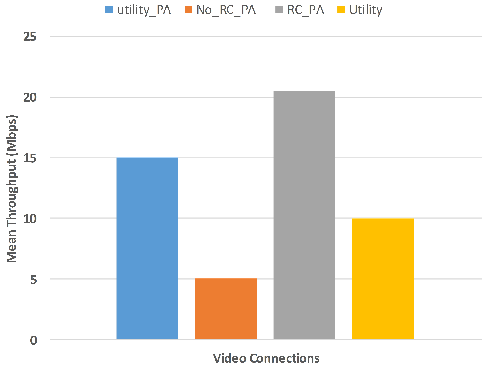
Figure 3 denotes the throughput of the video in all scenarios, and it is evident that the throughput of the video in our suggested solution is higher than the other methods due to the use of power allocation for mitigating interference. Furthermore, the adaptive solution is making use of a good quality of channel, when deciding to match between video rate and channel rate. As for the utility, it shows less throughput; however, if we combine it with power allocation, it achieves a good performance. Even though, this solution is using SINR for making the decision of matching; however, it is using an expected bandwidth for matching the rate that does not give the exact throughput. Both our solutions and utility do not perform well in terms of throughput when there is no power allocation.
As for the number of control messages exchanged between the device itself and the MBS, we remarked that it is higher when achieving rate control functionality and power allocation rather than its absence. This is a normal case as the measurement reports are sent so often to measure the quality of channels of FUEs and MUEs according to our algorithm. However, in the case when there is no rate control and power allocation, there will be almost no negotiation except for the conventional control messages sent by MBS (Figure 4).
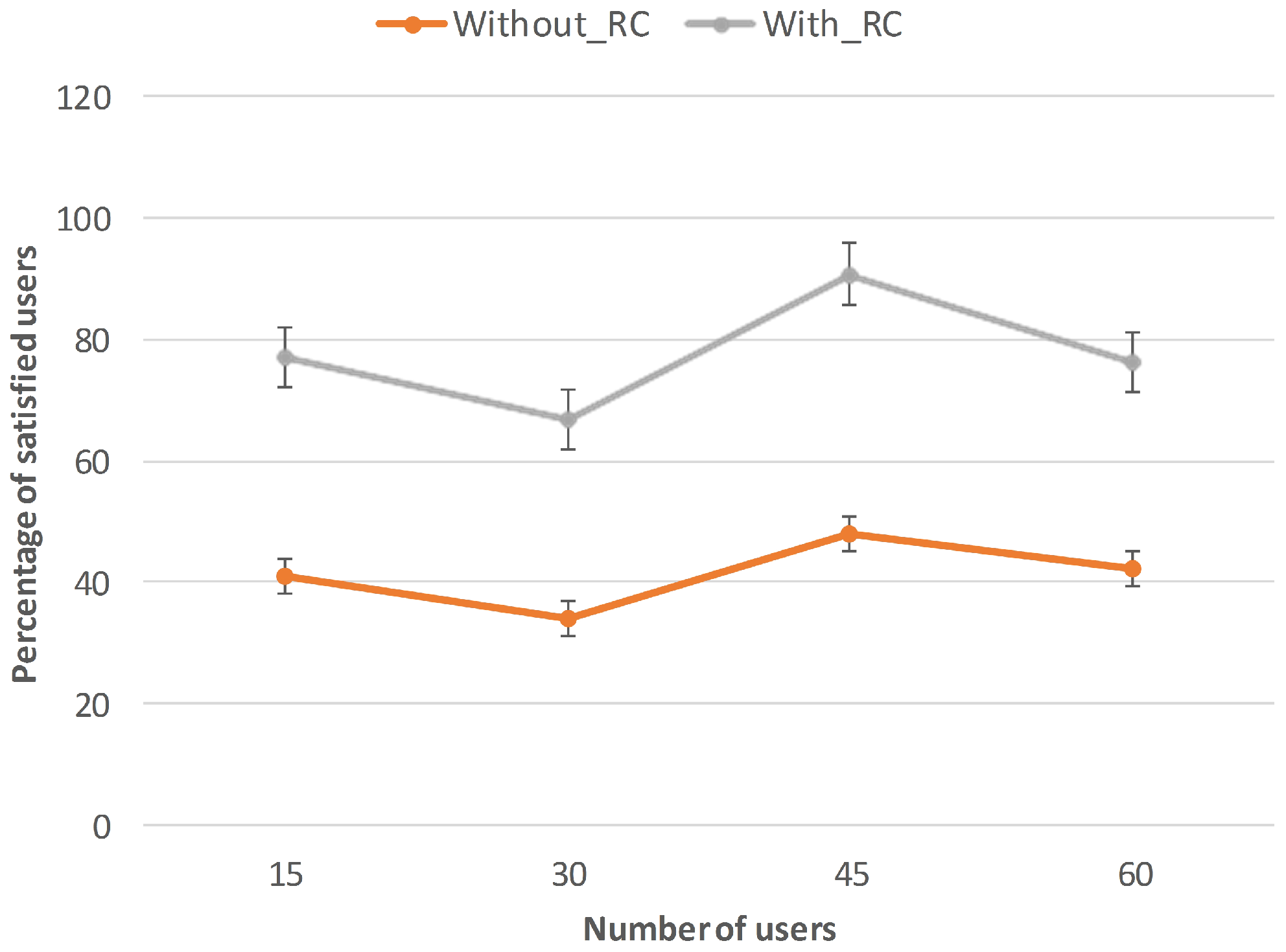
The percentage of satisfaction of the users is so important; in our case, it is related to the QoS guarantee for the parameter of throughput for video application. Figure 5 shows the percentage of satisfaction, which is from 70 to 90%, while using a rate adaptive algorithm with power allocation, while it is around 40–50% for the inverse case, i.e., rate control without power allocation, which is a natural result due to the interference issue.
Figure 6 shows the Packet Loss Ratio (PLR) of all methods regarding the number of users. It is clear that the PLR is increasing when the number of users is increasing; however, there is no violation of QoS of video streaming of interfered users using our method. This is due to the power allocation method that tries to decrease the power according to the Equations (7) and (11). The PLR is so high when there is no power allocation as interfered users will experience a very bad channel quality, compared to the utility method.
As for the QoE experienced by the users, the Mean Opnion Score (MOS) was used in relation with the objective metric mainly the PSNR. According to [30,31], the relationship between PSNR and MOS may be approximated by the bounded logarithmic function:
with
The parameters and denote the PSNR, which means that the perceived quality drop to “not acceptable” (MOS = 1.0) and exceeds “very satisfied” (MOS = 4.5), respectively.
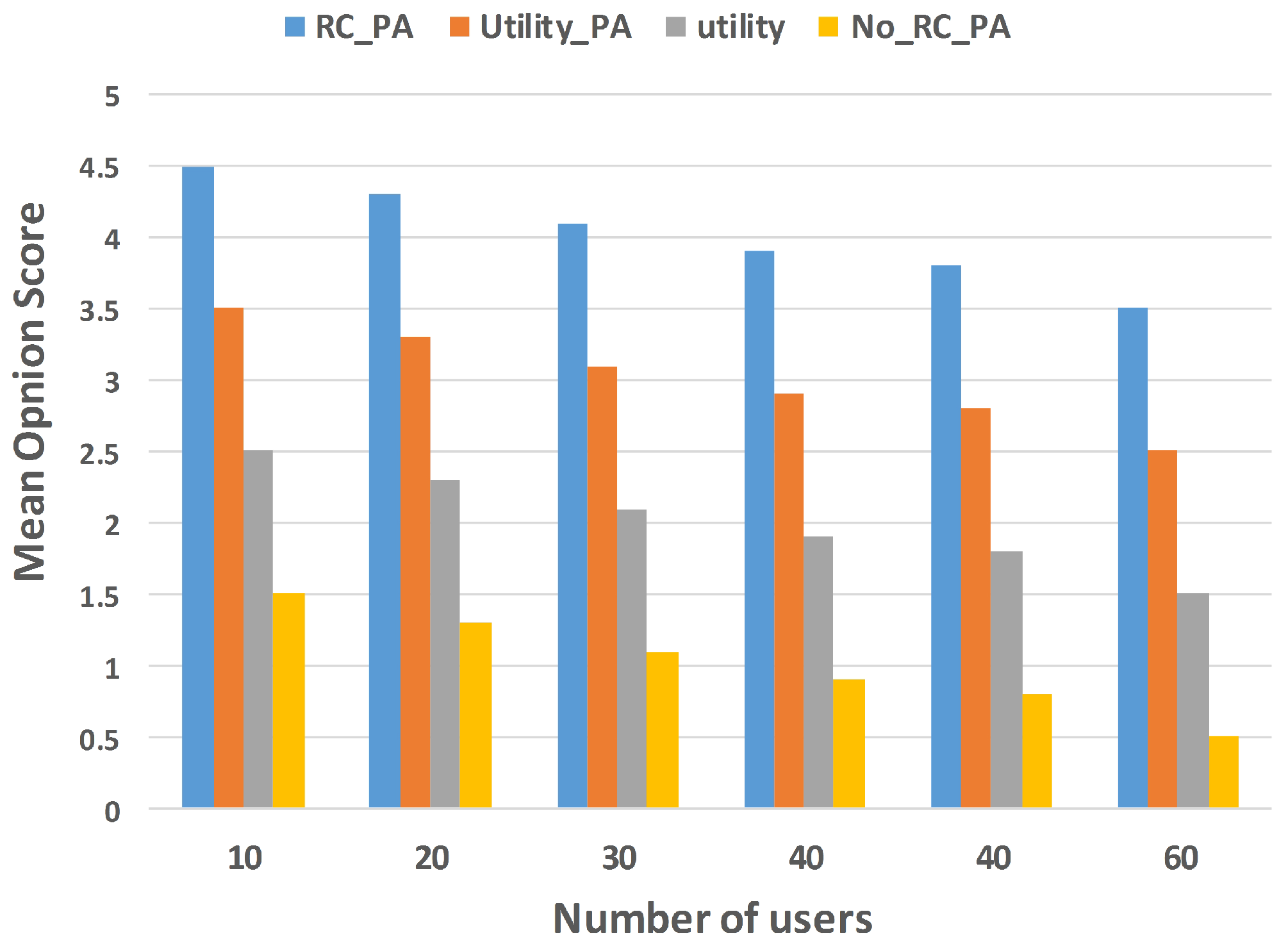
Form Figure 7, it is depicted that the MOS score for our method is higher than the other scores for other methods even when the number of users is increasing. The hybrid algorithm for power allocation is playing a good role in having good MOS since it is related to the data rate of the video. Then, as long as the data rate is high, the MOS score is better. This would mean better quality of PSNR, which is according to Equation (15), has a strict relation with MOS score. To interpret the simulation results, it is clear that the algorithms that are not using power allocation have lower MOS scores since the users who are experiencing interference will not have big data rates, and, consequently, lower PSNR and MOS scores. The conclusion can be even deduced from the relationship between Figure 6 and Figure 7.
7. Conclusions
In this article, we proposed a rate adaptive solution for a video streaming in an interference scenario based HetNet. We suggested a complete framework that first performs interference mitigation based on a hybrid method. This hybrid method is based on power control that is achieved in a combination of centralized and distributed schemes depending on the clustering method used to divide the network into clusters and sub-clusters of femtocell. Once the interference is mitigated, then the rate adaptation is carried out through the allocation of an appropriate number of resource blocks to the base layer of the video streaming traffic. This would guarantee the best quality for the video in terms of throughput and latency in terms of QoS. As for QoE, we studied the perception of the end user to the quality of the image that he/she received through a logarithmic relationship between MOS and PSNR. We proved that our method delivers the best QoS and QoE to the interfered users comparing to different methods in the literature.
Author Contributions
Tara Ali Yahiya and Pinar Kirci conceived and designed the experiments; Tara Ali Yahiya performed the experiments; Tara Ali Yahiya and Pinar Kirci analyzed the data and the simulation results; Pinar Kirci wrote the literature review section while Tara Ali Yahiya wrote the system design and the simulation results sections.
Conflicts of Interest
The authors declare no conflict of interest.
References
- Chandrasekhar, V.; Andrews, J.G.; Gatherer, A. Femtocell Networks: A Survey. IEEE Commun. Mag. 2008, 46, 59–67. [Google Scholar] [CrossRef]
- López-Pérez, D.; Valcarce, A.; Ladányi, A.; de la Roche, G.; Zhang, J. OFDMA Femtocells: A Roadmap on Interference Avoidance. IEEE Commun. Mag. 2009, 47, 41–48. [Google Scholar] [CrossRef]
- Yahiya, T.A. Understanding LTE and Its Performance, 1st ed.; Springer: New York, NY, USA, 2011; pp. 1–244. ISBN 978-1-4419-6457-1. [Google Scholar]
- Cisco. Cisco Visual Networking Index Predicts Global Annual IP Traffic to Exceed Three Zettabytes by 2021. Available online: Investor.cisco.com (accessed on 6 August 2017).
- Kumar, S.; Sarkar, A.; Sur, A. A Resource Allocation Framework for Adaptive Video Streaming over LTE. J. Netw. Comput. Appl. 2017, 97, 126–139. [Google Scholar] [CrossRef]
- Wu, J.; Yuen, C.; Cheng, B.; Wang, M.; Chen, J. Energy-Minimized Multipath Video Transport to Mobile Devices in Heterogeneous Wireless Networks. IEEE J. Sel. Areas Commun. 2016, 34, 1160–1178. [Google Scholar] [CrossRef]
- Abbas, N.; Hajj, H.; Dawy, Z.; Jahed, K.; Sharafeddine, S. An optimized approach to video traffic splitting in heterogeneous wireless networks with energy and QoE considerations. J. Netw. Comput. Appl. 2017, 83, 30–49. [Google Scholar] [CrossRef]
- Wu, J.; Cheng, B.; Wang, M.; Chen, J. Energy-Efficient Bandwidth Aggregation for Delay-Constrained Video Over Heterogeneous Wireless Networks. IEEE J. Sel. Areas Commun. 2017, 35, 30–49. [Google Scholar] [CrossRef]
- Wu, J.; Cheng, B.; Yuen, C.; Shang, Y.; Chen, J. Distortion-Aware Concurrent Multipath Transfer for Mobile Video Streaming in Heterogeneous Wireless Networks. IEEE Trans. Mob. Comput. 2015, 14, 688–701. [Google Scholar] [CrossRef]
- Petrangeli, S.; Wu, T.; Wauters, T.; Huysegems, R.; Bostoen, T.; Turck, F.D. A Machine Learning-Based Framework for Preventing Video Freezes in HTTP Adaptive Streaming. J. Netw. Comput. Appl. 2017, 94, 78–92. [Google Scholar] [CrossRef]
- Hwang, J.; Lee, J.; Yoo, C. Eliminating Bandwidth Estimation from Adaptive Video Streaming in Wireless Networks. Signal Process. Image Commun. 2016, 47, 242–251. [Google Scholar] [CrossRef]
- Zhao, M.; Gong, X.; Liang, J.; Wang, W.; Que, X.; Cheng, S. Qoe-Driven Cross-Layer Optimization for Wireless Dynamic Adaptive Streaming of Scalable Videos over Http. IEEE Trans. Circuits Syst. Video Technol. 2015, 25, 451–465. [Google Scholar] [CrossRef]
- Taha, M.; Lloret, J.; Canovas, A.; Garcia, L. Survey of Transportation of Adaptive Multimedia Streaming service in Internet. Netw. Protoc. Algorithms 2017, 9, 85–125. [Google Scholar] [CrossRef]
- Taha, M.; Garcia, L.; Jimenez, J.M.; Lloret, J. SDN-based throughput allocation in wireless networks for heterogeneous adaptive video streaming applications. In Proceedings of the 13th International Wireless Communications and Mobile Computing Conference (IWCMC 2017), Valencia, Spain, 26–30 June 2017. [Google Scholar]
- Liu, Y.; Liu, J.; Song, J.; Argyriou, A. Scalable 3D Video Streaming over P2P Networks with Playback Length Changeable Chunk Segmentation. J. Vis. Commun. Image Represent. 2015, 31, 41–53. [Google Scholar] [CrossRef]
- Kimball, J.; Wypych, T.; Kuester, F. Low Bandwidth Desktop and Video Streaming for Collaborative Tiled Display Environments. Future Gener. Comput. Syst. 2016, 54, 336–343. [Google Scholar] [CrossRef]
- Ho, D.; Park, Y.; Song, H. QoS-Supporting Video Streaming System with Minimum Data Service Cost over Heterogeneous Wireless Networks. J. Vis. Commun. Image Represent. 2013, 24, 1293–1302. [Google Scholar] [CrossRef]
- Moon, S.; Yoo, J.; Kim, S. Adaptive Interface Selection over Cloud-Based Split-Layer Video Streaming via Multi-Wireless Networks. Future Gener. Comput. Syst. 2016, 56, 664–674. [Google Scholar] [CrossRef]
- Tassi, A.; Chatzigeorgiou, I.; Vukobratovi’c, D. Resource-Allocation Frameworks for Network-Coded Layered Multimedia Multicast Services. IEEE J. Sel. Areas Commun. 2015, 33, 141–155. [Google Scholar] [CrossRef] [Green Version]
- Cordeschi, N.; Amendola, D.; Shojafar, M.; Baccarelli, E. Distributed and Adaptive Resource Management in Cloud-Assisted Cognitive Radio Vehicular Networks with Hard Reliability Guarantees. Veh. Commun. 2015, 2, 1–12. [Google Scholar] [CrossRef]
- Zhou, H.; Ji, Y.; Wang, X.; Zhao, B. Joint Resource Allocation and User Association for SVC Multicast Over Heterogeneous Cellular Networks. IEEE Trans. Wirel. Commun. 2015, 14, 3673–3684. [Google Scholar] [CrossRef]
- Choi, Y.I.; Kang, C.G. Scalable Video Coding-Based MIMO Broadcasting System with Optimal Power Control. IEEE Trans. Broadcast. 2017, 63, 350–360. [Google Scholar] [CrossRef]
- Yahiya, T.A. Adaptive Video Streaming Rate Control for HetNet Based on Interference Scenarios. In Proceedings of the IFIP Wireless and Mobile Networking Conference, Valencia, Spain, 25–27 September 2017. [Google Scholar]
- Kurda, R.; Yahiya, T.A.; Yiltas-Kaplan, D.; Kirci, P. A Cluster Based Scheme for Interference Mitigation in Mobile Macrocell-Femtocell Networks. In Proceedings of the 14th International Conference on ITS Telecommunications, Copenhagen, Denmark, 2–4 December 2015; pp. 60–64. [Google Scholar]
- Yang, J.; Ran, Y.; Chen, S.; Li, W.; Hanzo, L. Online Source Rate Control for Adaptive Video Streaming over HSPA and LTE-Style Variable Bit Rate Downlink Channels. IEEE Trans. Veh. Technol. 2016, 65, 643–657. [Google Scholar] [CrossRef]
- Yahiya, T.A.; Beylot, A.L.; Pujolle, G. An Adaptive Cross-Layer Design for Multiservice Scheduling in OFDMA Based Mobile WiMAX Systems. Comput. Commun. 2009, 32, 531–539. [Google Scholar] [CrossRef]
- Piro, G.; Grieco, L.A.; Boggia, G.; Capozzi, F.; Camarda, P. Simulating LTE Cellular Systems: An Open-Source Framework. IEEE Trans. Veh. Technol. 2011, 60, 498–513. [Google Scholar] [CrossRef]
- Kurda, R.; Boukhatem, L.; Yahiya, T.A. Interference Mitigation in Mobile Environment Through Power Adjustment in Macro and Femto Cell Systems. In Proceedings of the IEEE Wireless Communications and Networking Conference (WCNC), Istanbul, Turkey, 6–9 April 2014; pp. 1733–1738. [Google Scholar]
- Wang, X.; Chen, M.; Kwon, T.T.; Yang, L.; Leung, V.C.M. AMES-Cloud: A Framework of Adaptive Mobile Video Streaming and Efficient Social Video Sharing in the Clouds. IEEE Trans. Multimedia 2013, 15, 811–820. [Google Scholar] [CrossRef]
- Khan, S.; Duhovnikov, S.; Steinbach, E.; Sgroi, M.; Kellerer, W. Application-Driven Cross-Layer Optimization for Mobile Multimedia Communication Using a Common Application Layer Quality Metric. In Proceedings of the International Wireless Communications and Mobile Computing Conference (IWCMC ’06), Vancouver, BC, Canada, 3–6 July 2006; pp. 213–218. [Google Scholar]
- Nemethova, O.; Ries, M.; Zavodsky, M.; Rupp, M. PSNR Based Estimation of Subjective Time-Variant Video Quality for Mobiles. In Proceedings of the International Conference on Measurement of Audio and Video Quality in Networks (MESAQIN ’06), Prague, Czech Republic, 5–6 June 2006. [Google Scholar]
Figure 1.
Video streaming system architecture with HetNet.

Figure 2.
Flow diagram of the work.
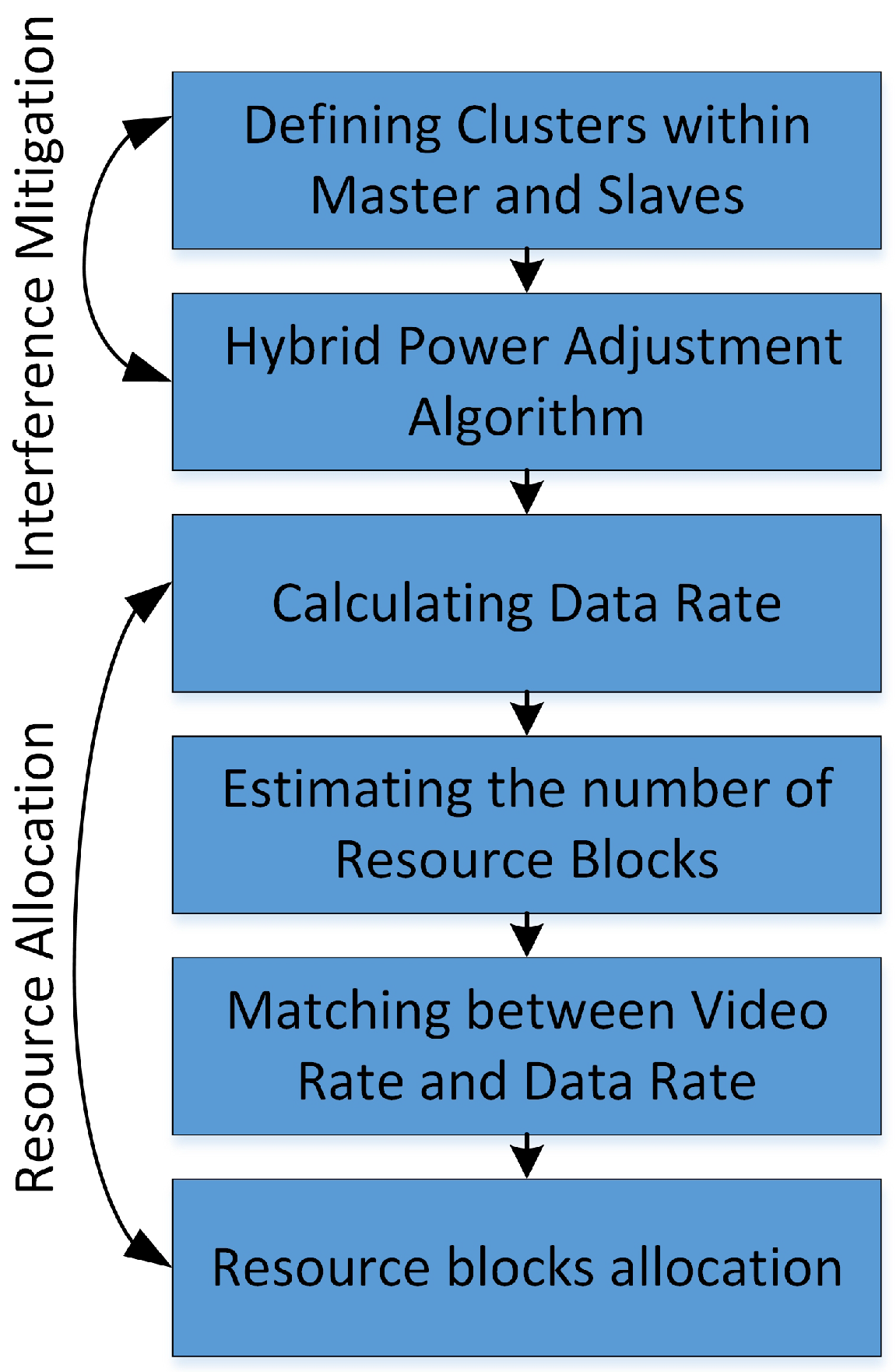
Figure 3.
Throughput of the video traffic.

Figure 4.
Average number of measurement reports sent by macrocell user equipments and femtocell user equipments.
Figure 4.
Average number of measurement reports sent by macrocell user equipments and femtocell user equipments.
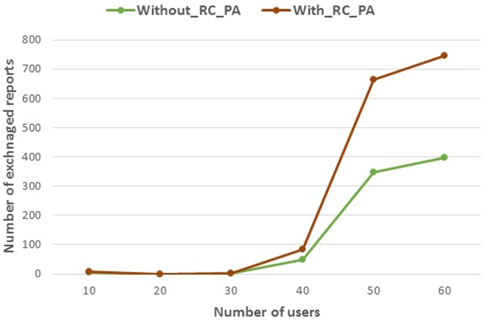
Figure 5.
Percentage of satisfied users in terms of throughput.

Figure 6.
Packet loss ratio vs. number of users.
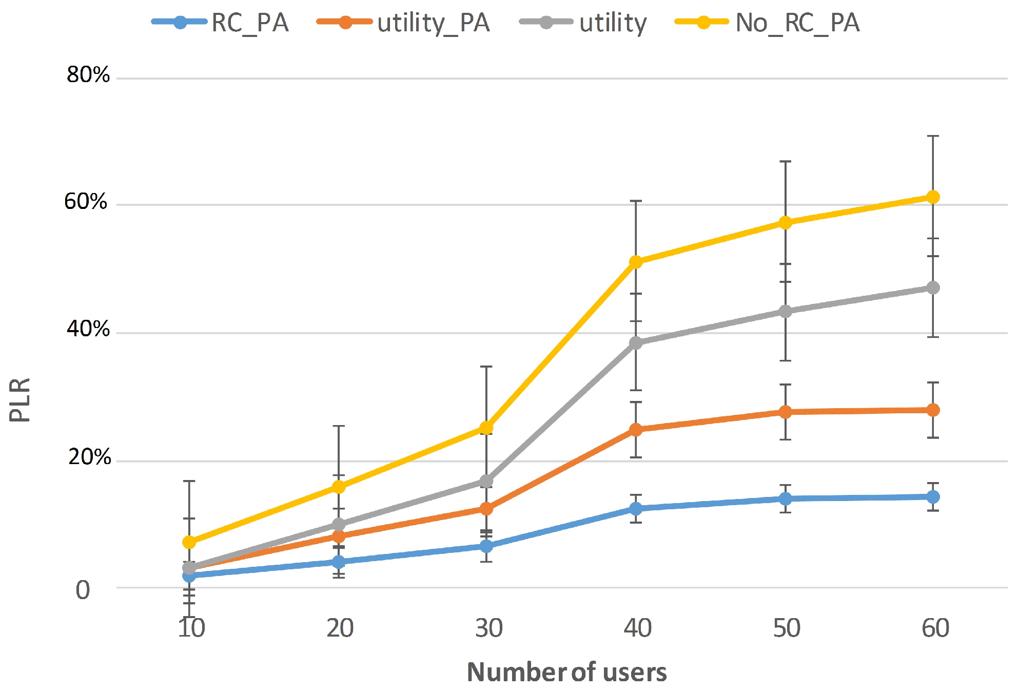
Figure 7.
MOS vs. number of users.


Table 1.
Table of acronyms.
| Acronym | Meaning |
|---|---|
| BL | Base Layer |
| CMT-DA | Distortion-Aware Concurrent Multipath Transfer |
| CQI | Channel Quality Indicator |
| CSG | Close Subscriber Group |
| DASH | Dynamic Adaptive Streaming over HTTP |
| DL | Downlink |
| EL | Enhancement Layer |
| ELBA | Energy-QuaLity Aware Bandwidth Aggregation |
| EVIS | Energy-Video Aware Multipath Transport Protocol |
| FBS | Femtocell Base Station |
| FDD | Frequency Division Duplex |
| FUE | Femtocell User Equipment |
| HAS | HTTP Adaptive Streaming |
| HetNet | Heterogeneous Networks |
| HTTP | Hypertext Transfer Protocol |
| ILP | Integer Linear Programming |
| LTE | Long-Term Evolution |
| LTE-A | Long-Term Evolution Advanced |
| MBS | Macrocell Base Station |
| MCS | Modulation and Coding Scheme |
| MIMO | Multi-Input Multioutput |
| ML | Machine Learning |
| MOS | Mean Opnion Score |
| MUE | Macrocell User Equipment |
| OFDMA | Orthogonal Frequency Division Multiple Access |
| PA | Power Allocation |
| PLC3DCS | Playback Length Changeable 3D Video Data Chunk Segmentation |
| PLR | Packet Loss Ratio |
| PSNR | Peak Signal-to-Noise Ratio |
| QoE | Quality of Experience |
| QoS | Quality of Service |
| RAN | Radio Access Network |
| RB | Resource Block |
| RSS | Received Signal Strength |
| SDN | Software Defined Network |
| SDQA | Streamlined DP-based Quality-level Allocator |
| SINR | Signal to Interference Noise Ratio |
| SVC | Scalable Video Coding |
| TCP | Transmission Control Protocol |
| TDD | Time Division Duplex |
| UL | Uplink |
| WLAN | Wireless Local Area Network |
| WQUAD | Wireless Quality Adaptation |
Table 2.
List of variables.
| Symbol | Meaning |
|---|---|
| M | A macrocell |
| A femtocell l | |
| L | Set of femtocells |
| I | Set of MUEs |
| J | Set of FUEs |
| K | Set of RBs |
| k | A RB k |
| A macrocell user i | |
| A femtocell user j | |
| Power of the additive White Gaussian noise | |
| SINR of a given associated with MBS M on RB k | |
| Channel fast fading gain between M and on RB k | |
| Channel fast fading gain between and the neighboring on RB k | |
| Set of all interfering FBSs on user on RB k | |
| Transmit power allocated on RB k by the serving cell M | |
| Received signal strength by from MBS M on RB k | |
| Received signal strength by from FBS on RB k | |
| Transmit power allocated on RB k by the serving femtocell | |
| New value of transmission power of femtocell on RB k | |
| Clusters | |
| y | Index of the cluster |
| Geographical position of the femtocell | |
| Repeated position | |
| Total number of MUE | |
| Average traffic rate for video connection i | |
| Q | Operational mode set of the video encoder |
| Path loss exponent with the distance between T and R | |
| Shadowing component | |
| Fast fading component | |
| X | Total number of MUEs and FUEs |
| Average traffic rate for video connection | |
| Average data rate for the RB k | |
| X | Total number of MUEs and FUEs |
| Rate of enhancement layer | |
| Rate of base layer |
Table 3.
Simulation parameters.
| Parameters | Values | Parameters | Values |
|---|---|---|---|
| Macrocells | 1 | Thermal noise density | −174 dBm/Hz |
| Femtocells | 30 | Carrier frequency | 3.5 GHz |
| MUEs | 15–60 | UE noise figure | 2.5 dB |
| FUEs | 4 | Macrocell radius | 500 m |
| bandwidth | 10 MHz | FUEs average speed | 3 km/h |
| RB bandwidth | 50 | MUEs average speed | 30 km/h |
| Macro Tx power | 43 dBm | 5.7 dB | |
| Femto Tx power | 23 dBm | Simulation Time | 60 s |
© 2018 by the authors. Licensee MDPI, Basel, Switzerland. This article is an open access article distributed under the terms and conditions of the Creative Commons Attribution (CC BY) license (http://creativecommons.org/licenses/by/4.0/).
Share and Cite
MDPI and ACS Style
Ali Yahiya, T.; Kirci, P. Performance Study of Adaptive Video Streaming in an Interference Scenario of Femto-Macro Cell Networks. Information 2018, 9, 22. https://doi.org/10.3390/info9010022
AMA Style
Ali Yahiya T, Kirci P. Performance Study of Adaptive Video Streaming in an Interference Scenario of Femto-Macro Cell Networks. Information. 2018; 9(1):22. https://doi.org/10.3390/info9010022
Chicago/Turabian StyleAli Yahiya, Tara, and Pinar Kirci. 2018. "Performance Study of Adaptive Video Streaming in an Interference Scenario of Femto-Macro Cell Networks" Information 9, no. 1: 22. https://doi.org/10.3390/info9010022
Note that from the first issue of 2016, this journal uses article numbers instead of page numbers. See further details here.