Hierarchical Guidance Strategy and Exemplar-Based Image Inpainting

1
College of Telecommunications and Information Engineering, Nanjing University of Posts and Telecommunications, Nanjing 210003, China
2
School of Computer and Information Engineering, Fuyang Normal University, Fuyang 236037, China
3
Jiangsu Province Key Laboratory on Image Processing and Image Communication, Nanjing 210003, China
4
School of Mathematics and Computer Science, Northwest Minzu University, Lanzhou 730030, China
*
Author to whom correspondence should be addressed.
†
Current address: No. 66, Xinmofan Road, Nanjing, Jiangsu, China.
‡
These authors contributed equally to this work.
Information 2018, 9(4), 96; https://doi.org/10.3390/info9040096
Submission received: 18 March 2018
/
Revised: 9 April 2018
/
Accepted: 15 April 2018
/
Published: 18 April 2018
(This article belongs to the Section Information Processes)
Abstract
:To solve the issue that it is difficult to maintain the consistency of linear structures when filling large regions by the exemplar-based technique, a hierarchical guidance strategy and exemplar-based image inpainting technique is proposed. The inpainting process is as follows: (i) the multi-layer resolution images are firstly acquired through decomposing of the pyramid on the target image; (ii) the top-layer inpainted image, the beginning of the inpainting from the top layer, is generated by the exemplar-based technique; (iii) there is a combined result between the next layer of the top image and the up-sampling output on the top-layer inpainted image, and the target regions are filled with information as guidance data; (iv) this process is repeated until the inpainting of all layers have been completed. Our results were compared to those obtained by existing techniques, and our proposed technique maintained the consistency of linear structures in a visually plausible way. Objectively, we choose SSIM (structural similarity index measurement) and PSNR (peak signal-to-noise ratio) as the measurement indices. Since the values of SSIM are well reflected when compared with other techniques, our technique clearly demonstrated that our approach is better able to maintain the consistency of linear structures. The core of our algorithm is to fill large regions whether they are synthesis images or real-scene photographs. It is easy to apply in practice, with the goal of having plausible inpainted image.
1. Introduction
Image inpainting belongs to the field of image retouching; users who do not see the original image accept the inpainting result on conditon that the restored image maintains visual consistency. Image inpainting, which is mainly used for speckles, scratches, damaged regions, the removal of objects, overlaid text or dates on the photo, etc., has a wide range of applications.
Since image inpainting was proposed by Bertalmio et al. [1], many scholars have begun to study image inpainting in recent years, and the representative inpainting approaches fall into two classes: The former is the technique based on variational partial differential. The typical methods proposed by Chan et al. [2,3,4] are the TV model, the curvature-driven model, and Euler’s elastica model, which efficiently fill small image regions but fill texture images poorly. The latter class is the exemplar-based technique proposed by Criminisi et al. [5], which has the advantages of simultaneously filling textures and structures using similar patches in the process of inpainting target regions, and some researchers have improved work in this area [6,7,8]. Xu et al. presented an exemplar-based sparse representation inpainting technique [9] using a dictionary composed of similar patches. In addition, the image is decomposed into two components that included a texture component and a structure component, and the output was the sum of the two components [10]. Exemplar-based wavelet decomposition and redefinition of the priority is also proposed by Padmavathi in [11]. Wavelet-based inpainting methods are further proposed in [12,13]. Pyramid decomposition inpainting is proposed in [14,15,16]; however, it was not well suited for recovering textures with large areas.
Liu et al. [17] proposed a method of multiscale graph cuts that uses minimum energy optimization. The alternating direction method for image inpainting in wavelet domains is proposed in [18]. These methods are based on multi-resolution inpainting. There are some researchers who have adopted deep neural networks for image inpainting. Xie et al. presented image denoising and inpainting with deep neural networks [19]. Additional methods with deep learning are proposed in [20,21,22,23], but they require a long training times when using for inpainting.
The image is decomposed into different image resolutions, as human beings observe the image from different distances. For example, we see the overall appearance from a long distance and observe local details from a near distance.
In our experiment we observed such a fact that the images of some level layer by pyramid decomposing are repaired with satisfaction, so in this case we think out outgrowth that well-pleasing filling result of some layer guide inpainting of next layer, until the original image is retouched well. As the target regions are reduced accordingly in a top layer decomposed by a pyramid, small regions are filled more effectively. The inpainting in the top layer of a pyramid focuses on the global optimization of the image, and the result of inpainting in the top layer then guides the next lower layer to fill target regions, so it seeks optimization in the global with a physically plausible and visually pleasing result.
Experimental results showed that the exemplar-based technique can achieve better results in different layers of the pyramid and that it could maintain the consistency of linear structures in the global domain. Therefore, we present a hierarchical guidance strategy in this paper.
After decomposing the pyramid in the original image, the target regions of the top layer are filled by the exemplar-based technique. The inpainted result is processed by up-sampling, and then combined with the next layer of the pyramid. The sum image contained information located in the target regions, which is considered as the guidance information when inpainting the next layer by the exemplar-based technique. The process is carried out repeatedly until all layers are filled. Compared to the results obtained by single inpainting, the proposed method in the paper can remarkably improve the effectiveness of inpainting.
2. Related Work
Image inpainting refers to filling target regions manually selected by the user or automatically marked by the algorithm (such as a segmentation algorithm). Pyramid decomposition means that several images with different resolutions are generated; with the increase in layers, the image resolutions become lower, and the area of target regions also become smaller. Therefore, filling small target regions should be repaired well with a satisfactory result. The exemplar-based technique [5] has two advantages of simultaneous filling texture and structure. Combining these two classes of techniques, we propose an exemplar-based technique and hierarchical guidance strategy inpainting algorithm in this paper.
2.1. Exemplar-Based Technique
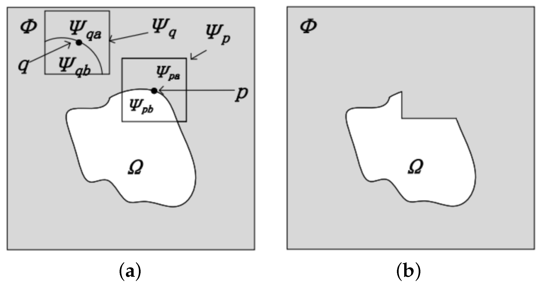
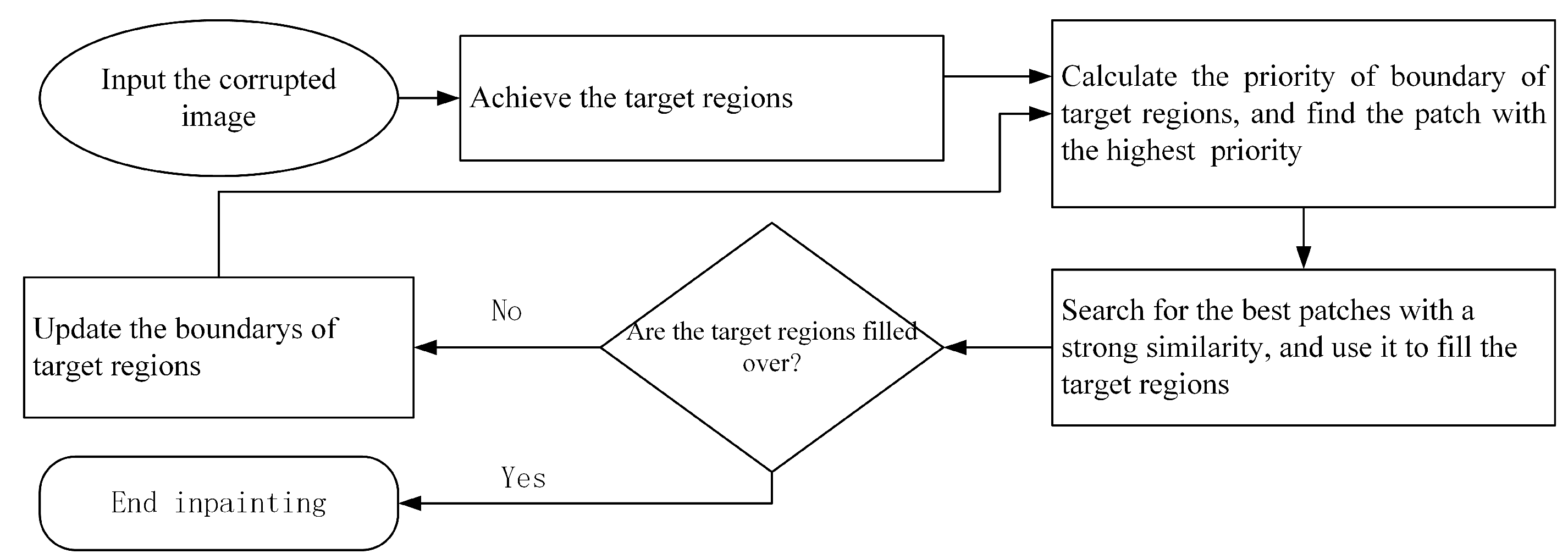
The exemplar-based technique is also known as texture synthesis inpainting. The main steps are as follows: (i) find a patch with the highest priority in the boundary between the target regions and source regions; (ii) look for the best similar patch and fill the region; (iii) update the priority of the boundary of the target regions, and (iv) repeat this process until the target regions are inpainted [5], as shown in Figure 1. Figure 1b shows the original image shown in Figure 1a filled once. The inpainting processing is shown in Figure 2.
2.2. Pyramid Decomposition
Pyramid decomposition is a kind of multi-scale representation of an image. In this paper, the pyramid decomposition consists in down-sampling only; that is, pyramid down-sampling in the K-layer image generates layer image. The cut-off frequency is gradually increased by a factor of 2 from the upper layer to the next layer, so the Gaussian pyramid generates a large frequency range [14].
Assuming that the 0th layer is the original image, denoted by , the first layer is denoted by , and the k-th layer is denoted by . Without a filtering operation in the pyramid decomposition process for avoiding the ambiguity of image decomposition, the upper image is one-fourth the time of the layer. The effectiveness maps are shown in Figure 3 using pyramid decomposing.
3. Hierarchical Guidance Strategy Inpainting
3.1. The Process of the Hierarchical Guidance Strategy
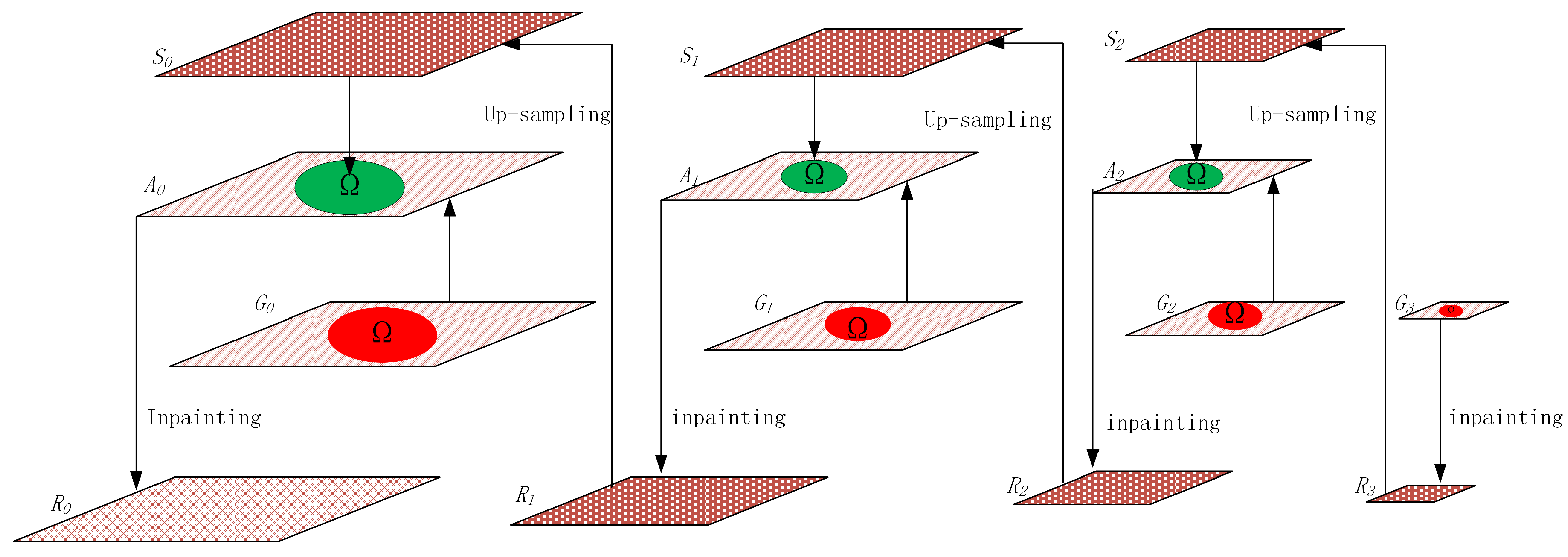
Multi-layer images are generated by pyramid decomposing of the original image if there are k layer images. First, the top layer is filled by the exemplar-based approach, and the output is an image. Second, the up-sampling of is carried out, and the output is an image. The target regions in the image are replaced by the regions that are located in the image, and the output is an image. Finally, the target regions in the image are filled. The filling information is rough and easy to blur, but the filled information is regarded as guidance information for searching the best patches. When looking for the best patches, the target regions will again be filled by the exemplar-based approach and the output is the image. The up-sampling result of will help the next layer fill the target regions, and this process is repeated until the target regions of the original image have been completely filled. The process is shown in Figure 4, and the process of image decomposition and inpainting is shown in Figure 5.
The top layer image, after pyramid decomposing, has a lower resolution, and the area of target regions is smaller. The process of inpainting starts at the top layer image. As the exemplar-based technique fills texture and structure simultaneously, we selected the exemplar-based approach to fill the image, so that the inpainted image would maintain the consistency of linear structures and texture and would have present plausible results.
Assuming that there is a point p on the edge of target regions (), the patch to be filled in which a point p locates in the center has two regions: a known part () and an unknown part (), which are shown in Figure 1a. The exemplar-based technique searches for the best exemplar in the image using the known part of patch , as illustrated in Figure 1. is calculated by Equation (1).
where is the sample of the entire image; patch is similar to , which has the lowest distance to patch ; is the distance including color and gradient between patch and patch , as shown in Equation (2).
where and are the vector of the RGB; and are the vector of the gradient of the image; is the weight representing the influence of the gradient. Both the pixel and the gradient are normalized.
The calculation of distance in [5] employs the color component, but we calculated the distance using color and gradient, so the candidate patches were subjected to a certain constraint, and the repaired image obtained was more aesthetically pleasing.
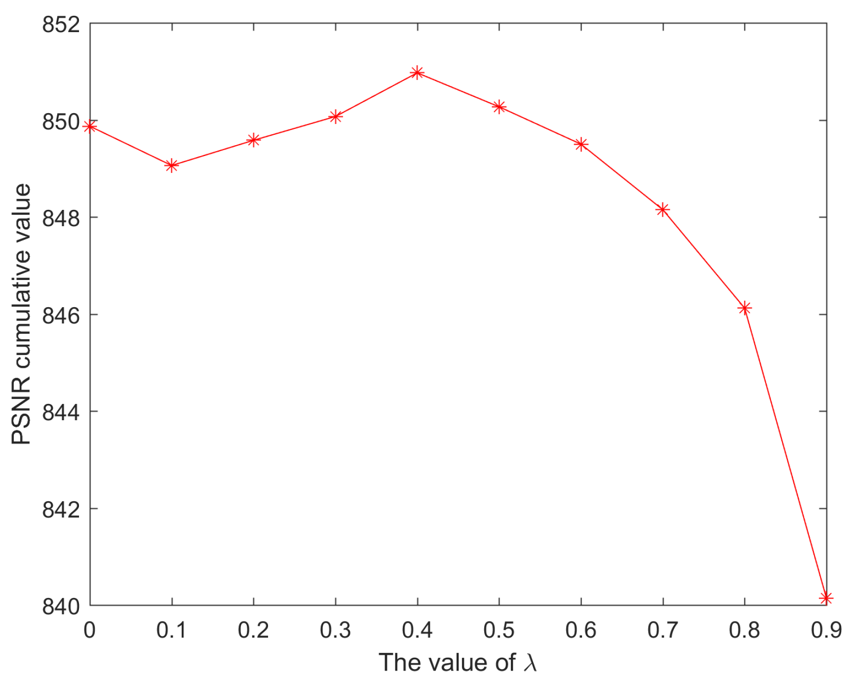
The weight needs to set a suitable value in Equation (2). This equation can constrain similar patches if the value of is small or is zero, which leads to the result that the structures may be blurry or missing. Otherwise, the large value generates mismatching. Hence, we calculate the PSNR (peak signal-to-noise ratio) cumulative value from 30 images with the same size and mask (mark the target regions). The PSNR cumulative values vary with different values as shown in Figure 6. The PSNR cumulative value achieves the maximum value with , so we fix the value of as 0.6 in all experiments to achieve the stability of our method.
3.2. Middle Layer Inpainting of Hierarchical Guidance
As the image resolution descends, the area of the target regions gradually diminishes from the bottom layer to the top layer by pyramid decomposing. We executed the strategy whereby the image was restored from the top layer to the bottom layer. The result of the inpainting in the top layer, once it is finished, can guide inpainting of the next layer. Assuming that the top layer image ( ) is restored, it is subjected to up-sample to obtain an image, and an image is created by merging the image and the image. Meanwhile, the target regions in are filled; however, by employing the exemplar-based technique, filling the target regions again will employ the pixels already filled (the pixels in the patch part of ) as the guidance information. Assuming the target patch is now searching for the best similar patch, is calculated by Equation (3).
where represents the known pixels, and is the guidance information. The distance is calculated by Equation (2). We extracted randomly 30 images for testing as shown in Figure 7, which denotes that gradient information is not used with , and comparison illustrates that the PSNR cumulative values are obvious when the best patch in the middle layer with a gradient distance defined by Equation (2) is being sought. The PSNR cumulative values are highest if , so is set for inpainting the middle layers for all experiments here.
To improve the visual effect of the inpainting result, we employ Possion blending [24] for post-processing.
The number of pyramid decomposition layers is limited, as this number generally relates to the size of the image and the area of the filling regions. Equation (4) is used to calculate the maximum number of levels of decomposition. Generally speaking, we do not take the maximum number of layers, and this number will be bound by the texture.
where , , , and are the target image width, image height, and the exemplar-patch width and height. For example, the target image size is 547 × 454 in Figure 8, and the patch size is 9 × 9, so we can calculate . In the process of decomposing, we pay attention to the fact that the area of filling regions in the top layer cannot be zero, since we here cannot fill any regions. Decomposing will stop when we detect that the filling region area is zero.
The hierarchical guidance strategy and exemplar-based image inpainting is expressed in Algorithm 1.
| Algorithm 1 Hierarchical guidance strategy and exemplar-based image inpainting. | |
| Input: The corrupted image I; The mask for identifying the target regions; | |
| Output: The restored image; | |
| 1: | Build the pyramid images with N layers |
| 2: | flag ← True |
| 3: | fordo |
| 4: | if flag is True then |
| 5: | When inpainting the top layer of pyramid using exemplar-based method, we can acquire |
| 6: | |
| 7: | the |
| 8: | flag ←False |
| 9: | end if |
| 10: | Obtain by up-sampling |
| 11: | Merging the image and image into image |
| 12: | The image is generated when restoring the image by exemplar-based technique and |
| 13: | |
| 14: | hierarchical guidance |
| 15: | end for |
| 16: | Achieve the result of inpainting( ) |
| 17: | Output possion blending result of |
4. Experimental Analysis
The patch size was set as when employing the hierarchical guidance strategy and exemplar-based image inpainting. The original image is the 1st layer.
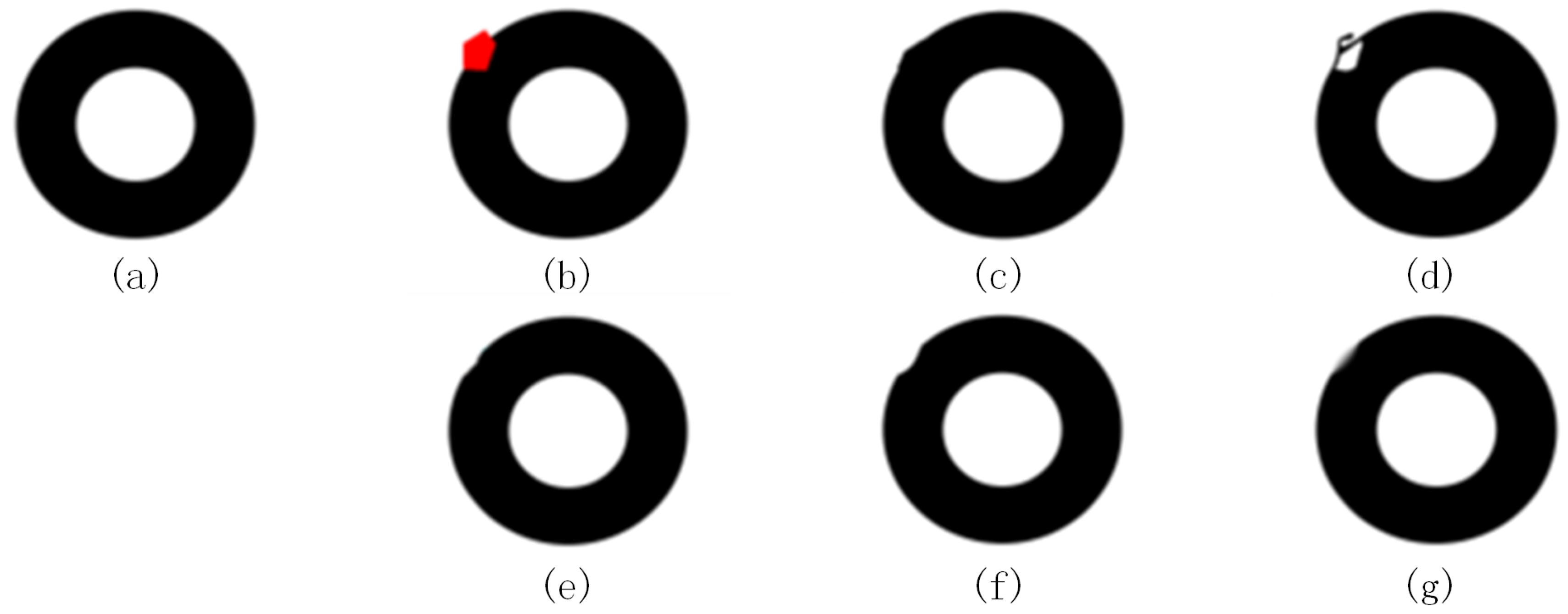
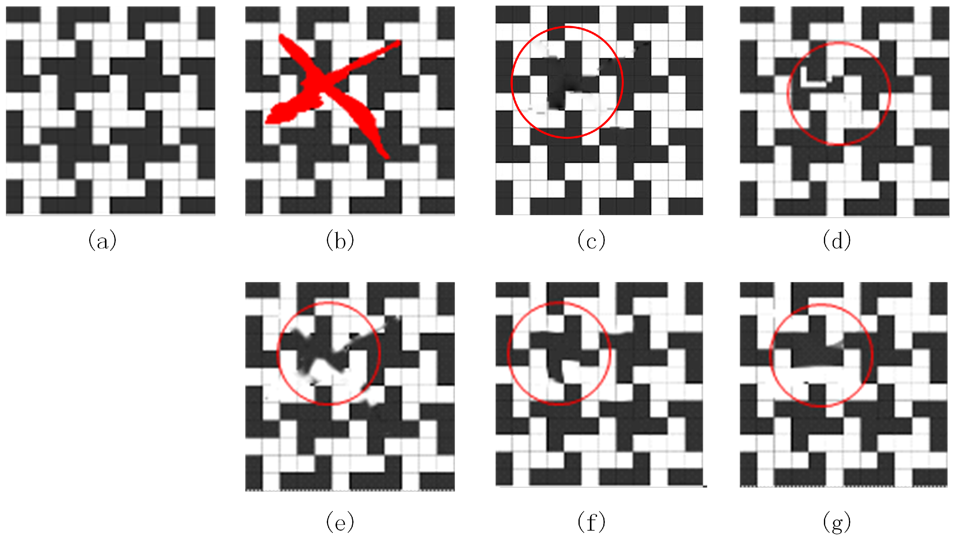
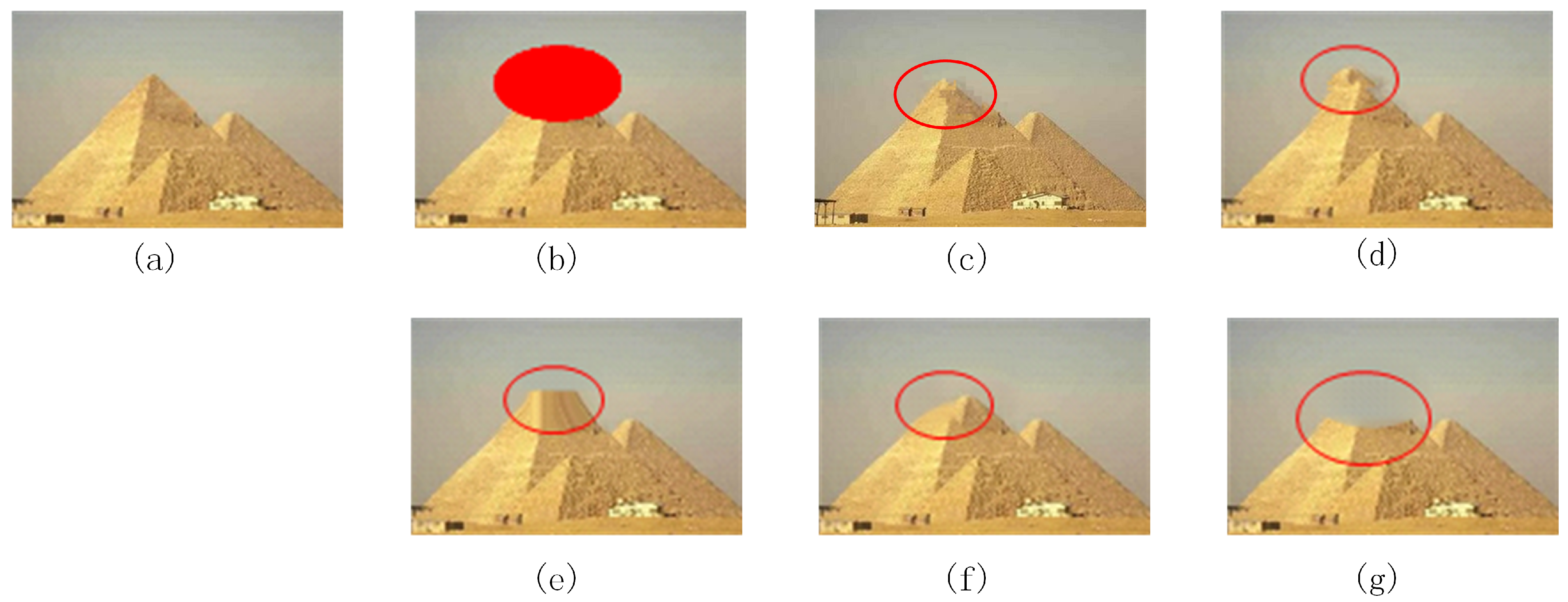
Simulation experiments are shown in Figure 8, Figure 9, Figure 10, Figure 11 and Figure 12 along with the existing methods for inpainting various types of images. From Figure 8 to Figure 12, (a) is the original image; (b) is the mask image; (c) is the inpainted image of our method; (d) is the inpainted image by the method proposed in [5]; (e) is the inpainted image by the method proposed in [25]; (f) is the inpainted image by the method proposed in [26]; (g) is the inpainted image by the method proposed in [27].
Figure 8a is a circle image. We set the number layer . Figure 8d is substantially different from Figure 8a, the arcs in Figure 8e,f are concaved, the boundary of the circle in Figure 8g shows a fuzzy effect, and Figure 8c shows little convexity. Thus, these inpainting techniques are different.
Figure 9a shows an image with certain structural rules. Here, the algorithm sets the layer number as . Figure 9d,g do not maintain the consistency of the structure; there was a certain degree of ambiguity near the boundary in Figure 9e,f; Figure 9c maintains the consistency of the structure where the inpainted image was satisfactory.
Figure 10a shows a pyramid image, the number of pyramid levels (N) is fixed as two. Inconsistency in the contours of the edges is apparent in Figure 10d,f, and there is no tower spire in Figure 10e. The effect of inpainting is obviously poor for the tower spire, which is not filled in Figure 10g. The image based on our method, as shown in Figure 10c, is very close to the original image, as it retains the structure of the image. Figure 10b shows that the target regions containing corners could not be easily repaired, so the many inpainting methods failed to repair the image.
Figure 11a shows an image of part of a zebra. Here, we set (the number of the pyramid level). The target regions simultaneously contained textures and structures as shown in Figure 11b with a green label. It can be seen from Figure 11d that the inpainted image is not aesthetically pleasing. The inpainted image has a certain degree of ambiguity. In Figure 11c,f, the inpainted image shows a plausible result which is close to the original image for maintaining the structure and holding textural coherence. In Figure 11g, the repair result shows a blurry effect, and in Figure 11e, the target region with line structure is not well filled.
Figure 12a shows an image of a bird. We set (the number of pyramid levels). The target regions in Figure 12b has three kinds of textures, structures, and smooths. We can see a near-acceptable inpainted image in Figure 12d with an extra twig and black spots in the bird’s chest. The inpainted image in Figure 12e is ambiguous, but the inpainted images in Figure 12f,g are reasonable; the inpainted image in Figure 12c, which is close to the original image, maintained consistency. From the experimental results seen in Figure 8, Figure 9, Figure 10, Figure 11 and Figure 12, we can conclude that the proposed method can maintain the consistency of structures and achieve a well-pleasing texture.
Here, a qualitative comparison of inpainted images is performed by calculating the PSNR and the SSIM, and it is demonstrated that, when the value of PSNR and SSIM is larger, the inpainted image is more satisfactory. The fact is that the inpainted image equals the original image when SSIM = 1. The PSNR is computed as
where the term MSE is the mean square error between the original image A and the processed image B; the term n is the depth of the pixel value, and the term denotes grayscale image. The SSIM is defined as
where , , , , and are the standard deviations, the cross-covariance, and the local means for images x and y. and are constant values. The PSNR and SSIM values of the inpainted image from Figure 8, Figure 9, Figure 10, Figure 11 and Figure 12, which is measured using our method and methods used in [5,25,26,27], respectively, are listed in Table 1 and Table 2. From Table 1, we can see that the PSNR value of our method is not always the highest when compared with others, but the analysis of the inpainted image by the human eye is well-pleasing. From Table 2, it is clear that the SSIM values of our method, in many circumstances, are satisfactory when compared with the others.
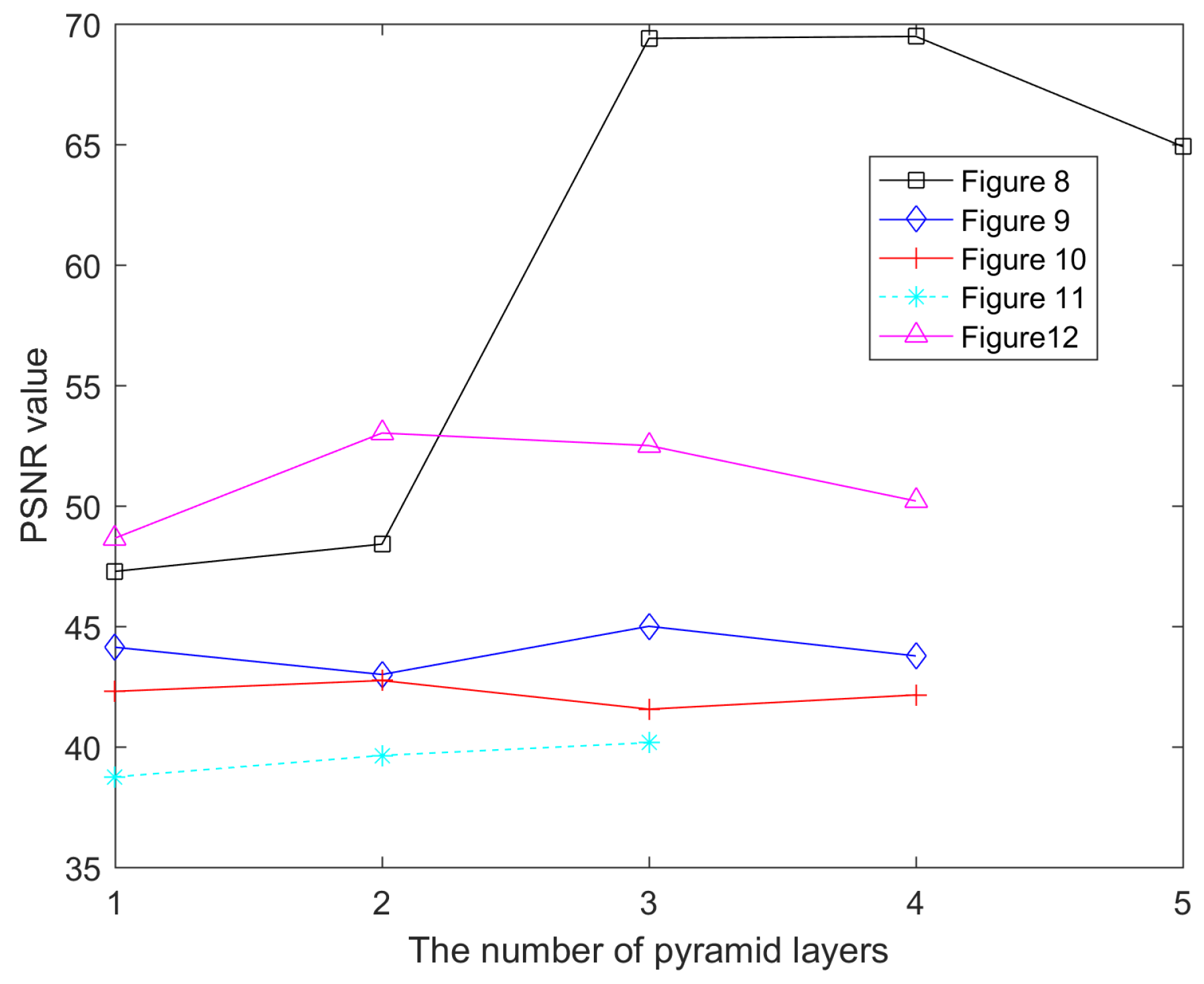
The experiments show that the layer number of pyramid decomposition will partly influence the inpainted image. The number of layers is generally related to the size of the image, the filling area, the shape of the target regions, and the texture. The target regions fall into two cases: One case is that target regions include texture, and target regions can be inpainted in a well-pleasing manner by decomposing a small number of layers (Figure 10, Figure 11 and Figure 12). Decomposing too many layers will increase the ambiguity of the output image. The other case is that target regions are non-textural, and the image needs to decompose more layers to acquire a satisfactorily inpainted image (Figure 8 and Figure 9). Figure 13 and Figure 14 show the relationship between the number of decomposed layers and both the PSNR values and the SSIM values respectively. Figure 13 and Figure 14 illustrate that the layer number of image decomposition influences image restoration. Poor inpainting of the top layer will affect the next repair and so will lead to unacceptable results of inpainting. However, small areas are much easier to repair than large areas, so the filling area of the top layer of the image is smaller. In general, it is easy to obtain satisfactory repair results. In many cases, how the top layer guides the next layer is the key to repair.
5. Conclusions
Due to the difficulty of maintaining structure consistency when large regions are repaired using the exemplar-based technique, a method that uses the hierarchical guidance strategy and exemplar-based inpainting technique is proposed here. Pyramid decomposing was applied to the top layer of an image for inpainting from a global view, and the inpainted image of the top layer then guided repair of the next layer. In other words, an inpainted layer guides inpainting of the next layer. There are two benefits to this: one is that the structures in the target regions are kept consistent with the global structure, and the other is that it decreases the candidate patches when the best exemplar using the guidance strategy for inpainting is sought. This demonstrates that the herein proposed method employing the hierarchical guidance strategy, which was compared with other methods and measured by objective evaluation of PSNR and SSIM, was applied successfully for inpainting. Our method needs to improve its performance in reducing sample resources through pyramid decomposition. Considering multiple resolutions, we can improve the inpainting effect by building a database and by further enriching the sample resources.
Acknowledgments
This work was supported in part by the National Natural Science Foundation of China (Grant No. 61162021), the Key Research and Development Program of Jiangsu Province (Grant No. BE2016775), the key fund projects of Young Talents in Fuyang Normal University (Grant No. rcxm201706), and the Natural Fund Project in Fuyang Normal University (Grant No.2017FSKJ17).
Author Contributions
Huaming Liu proposed the idea, designed and performed the simulations, and wrote the paper; Guanming Lu, Xuehui Bi, and Weilan Wang analyzed the data; all authors have read and approved the final manuscript.
Conflicts of Interest
The authors declare no conflict of interest.
References
- Bertalmio, M.; Sapiro, G.; Caselles, V.; Ballester, C. Image Inpainting. In Proceedings of the 27th Annual Conference on Computer Graphics and Interactive Techniques, New Orleans, LA, USA, 23–28 July 2000; pp. 417–424. [Google Scholar]
- Chan, T.F. Nontexture inpainting by curvature-driven diffusions. J. Vis. Commun. Image Represent. 2001, 12, 436–449. [Google Scholar] [CrossRef]
- Chan, T.F.; Kang, S.H.; Shen, J.H. Euler’s elastica and curvature-based inpainting. Siam J. Appl. Math. 2003, 63, 564–592. [Google Scholar]
- Shen, J.; Chan, T.F. Mathematical models for local nontexture inpaintings. SIAM J. Appl. Math. 2002, 62, 1019–1043. [Google Scholar] [CrossRef]
- Criminisi, A.; Perez, P.; Toyama, K. Region filling and object removal by exemplar-based image inpainting. IEEE Trans. Image Process. 2004, 13, 1200–1212. [Google Scholar] [CrossRef] [PubMed]
- Drori, I.; Cohen-Or, D.; Yeshurun, H. Fragment-based image completion. ACM Trans. Graph. (TOG) 2003, 22, 303–312. [Google Scholar] [CrossRef]
- Lee, J.; Lee, D.K.; Park, R.H. Robust exemplar-based inpainting algorithm using region segmentation. IEEE Trans. Consum. Electron. 2012, 58, 553–561. [Google Scholar] [CrossRef]
- Zhang, Q.; Lin, J. Exemplar-based image inpainting using color distribution analysis. J. Inf. Sci. Eng. 2012, 28, 641–654. [Google Scholar]
- Xu, Z.B.; Sun, J. Image Inpainting by Patch Propagation Using Patch Sparsity. IEEE Trans. Image Process. 2010, 19, 1153–1165. [Google Scholar] [PubMed]
- Bertalmio, M.; Vese, L.; Sapiro, G.; Osher, S. Simultaneous structure and texture image inpainting. IEEE Trans. Image Process. 2003, 12, 882–889. [Google Scholar] [CrossRef] [PubMed]
- Padmavathi, S.; Soman, B.P.; Soman, K.P. Hirarchical Digital Image Inpainting Using Wavelets. Signal Image Process 2012, 3, 85. [Google Scholar] [CrossRef]
- Ignácio, U.A.; Jung, C.R. Block-based image inpainting in the wavelet domain. Vis. Comput. 2007, 23, 733–741. [Google Scholar] [CrossRef]
- Wang, F.; Liang, D.; Wang, N.; Cheng, Z.; Tang, J. An new method for image inpainting using wavelets. In Proceedings of the 2011 International Conference on Multimedia Technology, Hangzhou, China, 26–28 July 2011; pp. 201–204. [Google Scholar]
- Burt, P.J.; Adelson, E.H. The Laplacian pyramid as a compact image code. In Readings in Computer Vision; Elsevier: Amsterdam, The Netherlands, 1987; pp. 671–679. [Google Scholar]
- Farid, M.S.; Khan, H.; Mahmood, A. Image inpainting based on pyramids. In Proceedings of the 2010 IEEE 10th International Conference on Signal Processing (ICSP), Beijing, China, 24–28 October 2010; pp. 711–715. [Google Scholar]
- Kim, B.S.; Kim, J.; Park, J. Exemplar based inpainting in a multi-scaled space. Opt. Int. J. Light Electron Opt. 2015, 126, 3978–3981. [Google Scholar] [CrossRef]
- Liu, Y.Q.; Caselles, V. Exemplar-Based Image Inpainting Using Multiscale Graph Cuts. IEEE Trans. Image Process. 2013, 22, 1699–1711. [Google Scholar] [PubMed]
- Chan, R.H.; Yang, J.F.; Yuan, X.M. Alternating Direction Method for Image Inpainting in Wavelet Domains. Siam J. Imaging Sci. 2011, 4, 807–826. [Google Scholar] [CrossRef]
- Xie, J.; Xu, L.; Chen, E. Image denoising and inpainting with deep neural networks. In Proceedings of the 25th International Conference on Neural Information Processing Systems, Lake Tahoe, NV, USA, 3–6 December 2012; pp. 341–349. [Google Scholar]
- Cai, N.; Su, Z.; Lin, Z.; Wang, H.; Yang, Z.; Ling, B.W.K. Blind inpainting using the fully convolutional neural network. Vis. Comput. 2017, 33, 249–261. [Google Scholar] [CrossRef]
- Köhler, R.; Schuler, C.; Schölkopf, B.; Harmeling, S. Mask-specific inpainting with deep neural networks. In Proceedings of the German Conference on Pattern Recognition, Muenster, Germany, 2–5 September 2014; pp. 523–534. [Google Scholar]
- Pathak, D.; Krahenbuhl, P.; Donahue, J.; Darrell, T.; Efros, A.A. Context encoders: Feature learning by inpainting. In Proceedings of the 2016 IEEE Conference on Computer Vision and Pattern Recognition (CVPR), Las Vegas, NV, USA, 26 June–1 July 2016; pp. 2536–2544. [Google Scholar]
- Yang, C.; Lu, X.; Lin, Z.; Shechtman, E.; Wang, O.; Li, H. High-resolution image inpainting using multi-scale neural patch synthesis. In Proceedings of the 2017 IEEE Conference on Computer Vision and Pattern Recognition (CVPR), Honolulu, HI, USA, 21–26 July 2017; pp. 4076–4084. [Google Scholar]
- Pérez, P.; Gangnet, M.; Blake, A. Poisson image editing. ACM Trans. Graph. (TOG) 2003, 22, 313–318. [Google Scholar] [CrossRef]
- Telea, A. An image inpainting technique based on the fast marching method. J. Graph. Tools 2004, 9, 23–34. [Google Scholar] [CrossRef]
- Barnes, C.; Shechtman, E.; Finkelstein, A.; Goldman, D.B. PatchMatch: A randomized correspondence algorithm for structural image editing. ACM Trans. Graph.-TOG 2009, 28, 24. [Google Scholar]
- Getreuer, P. Total variation inpainting using split Bregman. Image Process. Line 2012, 2, 147–157. [Google Scholar] [CrossRef]
Figure 1.
The image inpainting using exemplar-based technique. (a) The regions to be inpainted; (b) The inpainted result.
Figure 1.
The image inpainting using exemplar-based technique. (a) The regions to be inpainted; (b) The inpainted result.

Figure 2.
The inpainting process of the exemplar-based technique.

Figure 3.
The pyramid decomposition of an image.
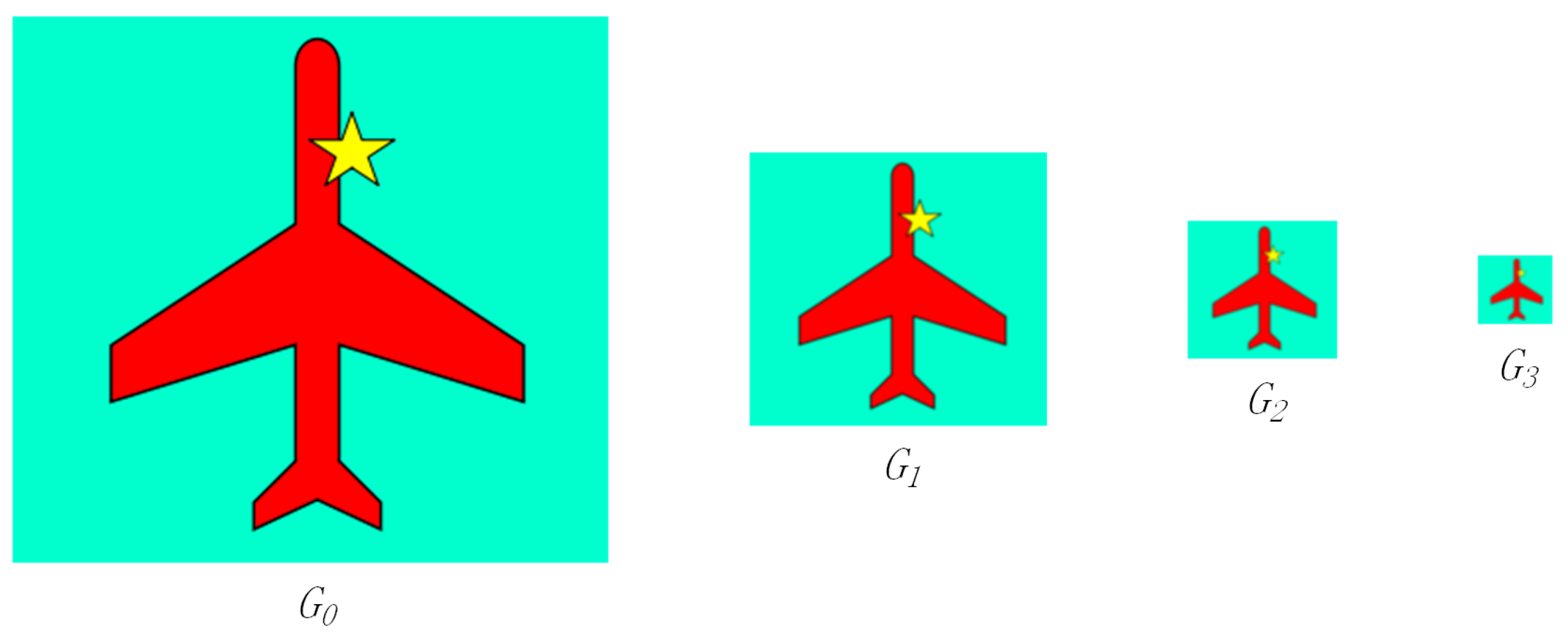
Figure 4.
The flow chart of inpainting using the pyramid layer guidance.
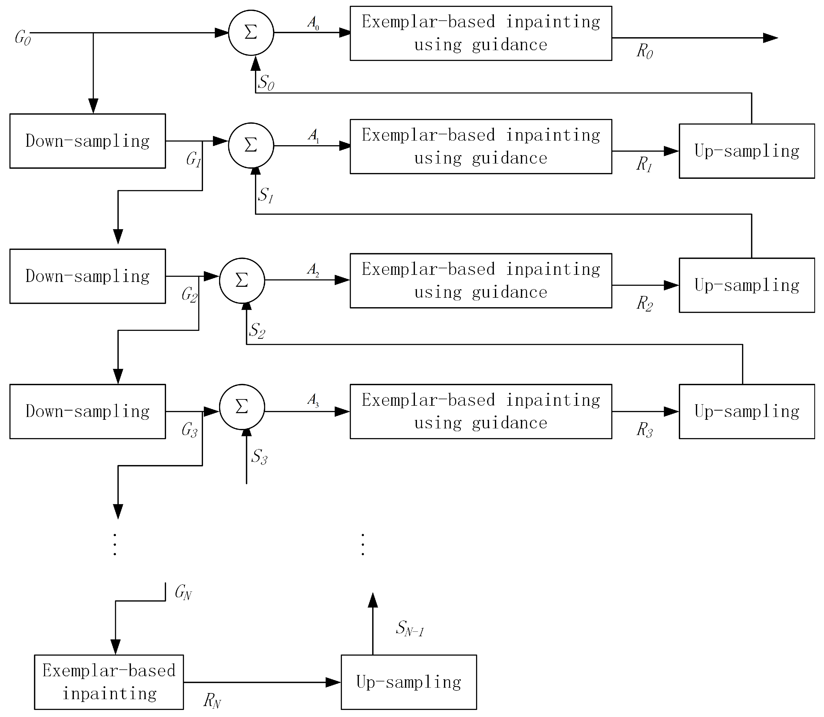
Figure 5.
Diagram of inpainting.

Figure 6.
PSNR (peak signal-to-noise ratio) cumulative values vary with different values.
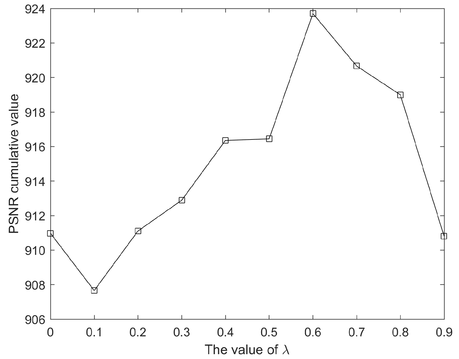
Figure 7.
The influence of using gradient information on the middle layer inpainting.

Figure 8.
The circle image inpainting. (a) The original image; (b) the mask image; (c) our method; (d) literature [5]; (e) literature [25]; (f) literature [26]; (g) literature [27].

Figure 9.
The square image inpainting. (a) original image; (b) mask image; (c) our method; (d) the method proposed in [5]; (e) the method proposed in [25]; (f) the method proposed in [26]; (g) the method proposed in [27].

Figure 10.
Pyramid image inpainting. (a) the original image; (b) the mask image; (c) our method; (d) the method proposed in [5]; (e) the method proposed in [25]; (f) the method proposed in [26]; (g) the method proposed in [27].

Figure 11.
Zebra image inpainting. (a) the original image; (b) the mask image; (c) our method; (d) the method proposed in [5]; (e) the method proposed in [25]; (f) the method proposed in [26]; (g) the method proposed in [27].
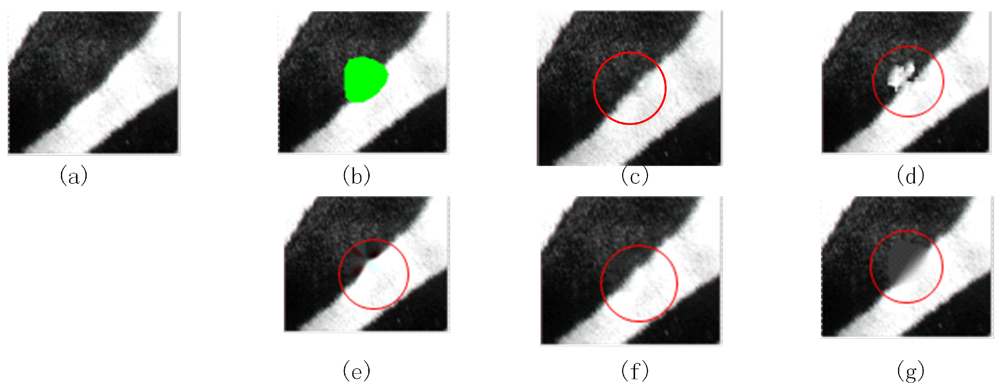
Figure 12.
Bird image inpainting. (a) the original image; (b) the mask image; (c) our method; (d) the method proposed in [5]; (e) the method proposed in [25]; (f) the method proposed in [26]; (g) the method proposed in [27].
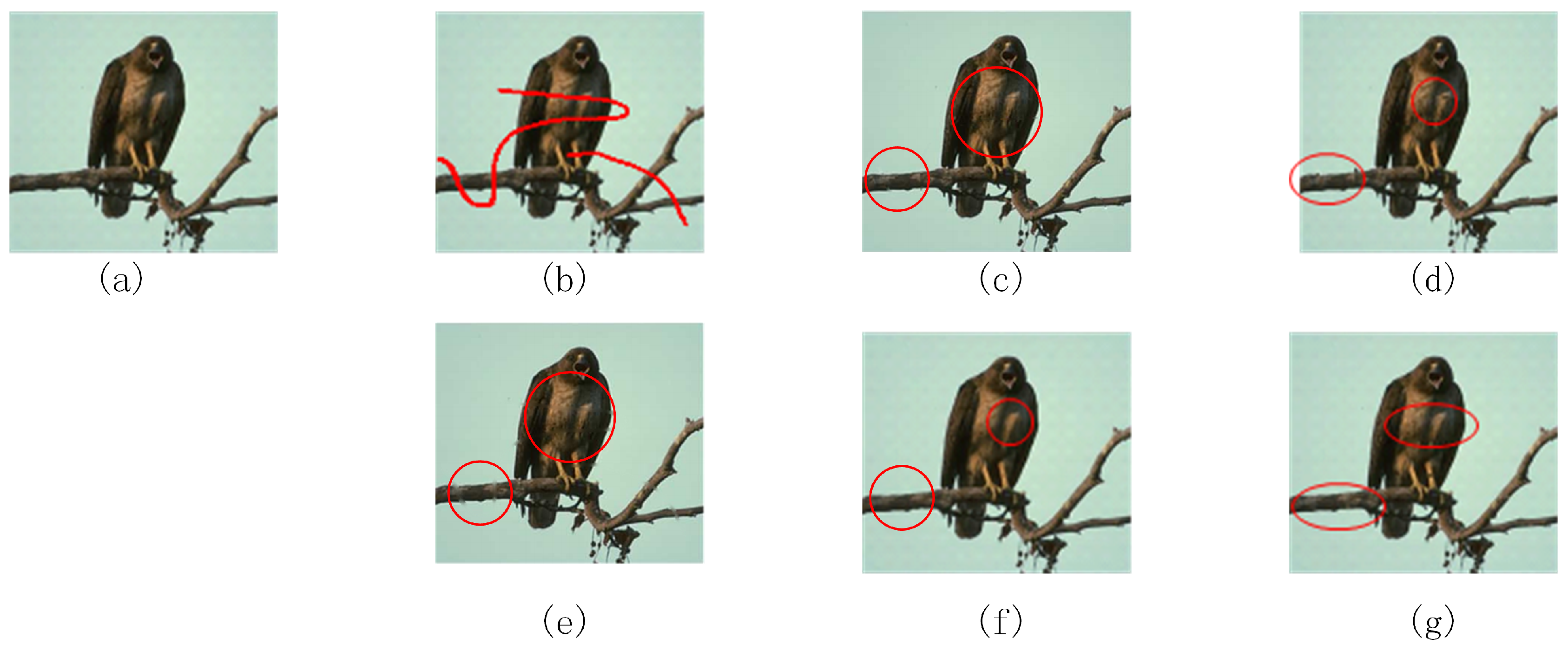
Figure 13.
The relationship between the hierarchical number of images and PSNR.

Figure 14.
The relationship between the hierarchical number of images and SSIM.


© 2018 by the authors. Licensee MDPI, Basel, Switzerland. This article is an open access article distributed under the terms and conditions of the Creative Commons Attribution (CC BY) license (http://creativecommons.org/licenses/by/4.0/).
Share and Cite
MDPI and ACS Style
Liu, H.; Lu, G.; Bi, X.; Wang, W. Hierarchical Guidance Strategy and Exemplar-Based Image Inpainting. Information 2018, 9, 96. https://doi.org/10.3390/info9040096
AMA Style
Liu H, Lu G, Bi X, Wang W. Hierarchical Guidance Strategy and Exemplar-Based Image Inpainting. Information. 2018; 9(4):96. https://doi.org/10.3390/info9040096
Chicago/Turabian StyleLiu, Huaming, Guanming Lu, Xuehui Bi, and Weilan Wang. 2018. "Hierarchical Guidance Strategy and Exemplar-Based Image Inpainting" Information 9, no. 4: 96. https://doi.org/10.3390/info9040096
Note that from the first issue of 2016, this journal uses article numbers instead of page numbers. See further details here.