Make Flows Great Again: A Hybrid Resilience Mechanism for OpenFlow Networks

Center for Informatics, Federal University of Pernambuco, Recife 50740-560, Brazil
Information 2018, 9(6), 146; https://doi.org/10.3390/info9060146
Submission received: 2 April 2018
/
Revised: 29 May 2018
/
Accepted: 13 June 2018
/
Published: 15 June 2018
(This article belongs to the Section Information and Communications Technology)
Abstract
:A top concern in Software-Defined Networking (SDN) is the management of network flows. The resource limitation in SDN devices, e.g., Ternary Content Addressable Memory (TCAM) size, and the signaling overhead between the control and data plane elements can impose scalability restrictions for a network. A notable SDN technology is the OpenFlow protocol, and failures in links and nodes inside an OpenFlow network could lead to drawbacks, such as packet loss. This work proposes the Local Node Group fast reroute (LONG), a hybrid resilience mechanism for OpenFlow networks that combines protection and restoration resilience mechanisms. The results achieved indicate that LONG is a practical approach when compared against the state-of-the-art algorithms.
1. Introduction
Software-Defined Networking (SDN) is emerging as a new paradigm [1,2,3,4], which proposes to avoid the vertical integration and separation of logic control from devices to promote innovation. SDN enables a global view and network programmability of the infrastructure through its centralized network management approach based on the so-called SDN controller [5,6].
There are some instances of the concepts of SDN [7], and one of them is the OpenFlow protocol [8]. The OpenFlow protocol (a standardized open interface) allows an OpenFlow controller to program the Forwarding Information Base (FIB) of OpenFlow switches [8]. In an OpenFlow network, the flows are deployed with Ternary Content Addressable Memory (TCAM) [9]. TCAM memories are very fast, however with the limitation of being of high cost and high energy consumption. In addition, currently OpenFlow switches have between ∼500 and 2500 OpenFlow rules [10] (with high-end switches supporting more than 100,000 rules), and the effective use of OpenFlow switches memory is vital to operating OpenFlow networks, especially in cases of failures. Besides the memory limitation, the SDN controller has to maintain a consistent view of the network state [11,12]. Depending on the approach to fetch the information about the network state, the signaling between the switches and controller can play a crucial role in the network communication overhead.
Furthermore, it is essential to have a minimal guarantee that the network will remain available and operational, even when part of the network goes down (e.g., caused by a link failure). For OpenFlow networks, the resilient mechanisms are approaches that seek to bring minimal guarantees for the network connectivity. Previous works basically classified two types of resilient mechanisms for OpenFlow networks [13,14]: restoration (uses a reactive strategy), where in the presence of a link failure, the controller reacts by signaling the data plane elements to restore the broken flows affected by the failure; and protection (uses a proactive strategy), when backup paths are configured and installed in advance before failures occur.
Decoupling hardware and software of network devices is a major feature of SDN and hence imposes more latency for restoration resilience mechanisms due to communication between data and control plane elements. However, this approach makes the network state maintenance more straightforward, once the failure event is notified to the controller.
One fast protection resilience mechanism is specified in the OpenFlow protocol, the Fast Failover Group Table [15] (FF). Since OpenFlow Version 1.1, the specification depicts the implementation of the Fast Failover Group Table, a resilience mechanism located in an OpenFlow switch that could change primary paths to backup paths in the presence of link failure. The main goal is to decrease the unavailable time of the network after a link failure.
Thus, an OpenFlow switch with FF can take local action to restore the failure without the requirement of communicating the failure to the OpenFlow controller. Although FF notoriously reduces the recovery time after a link failure [14,16,17], it produces an inconsistency of the network state inside the controller, as all restoration processes occur at the data plane level (OpenFlow switches). Hence, the inconsistency in the control plane level (controller) could lead to a suboptimal bandwidth and TCAM memory utilization, as well as increase the latency in network flows.
Thus, as far as we know, none previous works were designed to mix protection and recovery mechanisms to mitigate the effects of failure links inside OpenFlow networks. The extensive survey [18] also highlights the necessity of a hybrid approach in the field. Therefore, this work proposes the Local Node Group fast reroute (LONG), a resilience mechanism for OpenFlow networks that applies an aggregation technique to keep the number of OpenFlow rules installed minimal and uses an active strategy, which mixes the benefits of proactive and reactive strategies for resilience mechanisms without losing the global view of the network state. The main contributions of this work are:
The remainder of this paper is organized as follows: Section 2 presents preliminary concepts about OpenFlow and resilience mechanisms; Section 3 depicts related works; Section 4 details LONG’s logic; Section 5 describes the performance evaluation executed; Section 6 discusses the main results of this paper; and finally, Section 7 provides the final thoughts.
2. Preliminaries
Resilience mechanisms are vital for SDN networks. They assist network operators to reach high levels of availability. However, to apply a resilience mechanism, the controller has to be aware of the state of the network. One element of the network state is the topology. Thus, a brief review of how the SDN controller can fetch the topology information is given in the next subsection.
2.1. Topology Discovery
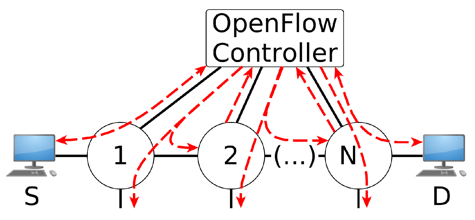
The topology discovery process can be reached using flood messages. Figure 1 depicts a process of discovering the topology in an OpenFlow network, where the long dashed lines represent the control packets from/to OpenFlow switches or hosts. This process intensively uses the OpenFlow flood port [19], where an incoming packet is distributed to all physical ports except the input port and those disabled by the Spanning Tree Protocol (STP). Obviously, the switching loop treatment has to be done to avoid broadcast storms during the discovery process of the SDN topologies with cycles.
The SDN controller is responsible for acquiring physical network information, such as links and OpenFlow switches’ identifications and features (e.g., supported link rates of each switch port). It also creates a logical abstraction of the representation of the physical topology that can be properly used by the other components. Regarding implementation, one discovery protocol, used in Ethernet networks, that provides topology discovery is the Link Layer Discovery Protocol (LLDP).
Besides, the controller also monitors the underlying infrastructure to maintain topology consistency. If a link suffers a failure, it is expected that the controller receives status information from the OpenFlow switch via the OFPT_PORT_STATUSmessage notification [19]. Thus, it is expected that every modification on the topology is communicated to the controller, and then, it provides an appropriated treatment to keep the consistency of the topology and network state. The controller can also use either Loss Of Signal (LOS) or Bidirectional Forwarding Detection (BFD) [20] to detect link failure.
2.2. OpenFlow Fast Failover Group Table
An OpenFlow network uses the concept of flow to carry traffic inside the network. A flow is a sequence of packets sent from a particular source to a particular destination following a given path [5], where the packets match the same fields values of a flow entry. A path is an ordered sequence of OpenFlow switches and links from the origin to the destination. In an OpenFlow switch, the flow entry matched fields, in a flow table, include Layer 2, 3 or 4 header information, the ingress port or the metadata values [19].
As explained in the work of [21], which proposes an SDN resilience mechanism implemented in hardware that use OpenState [22] (an extension of the OpenFlow specification for stateful packet processing), the resilience mechanism deployed in hardware has a notorious minimal unavailability time in comparison with software approaches. Thus, since OpenFlow Version 1.1, the OpenFlow specification provides the implementation of the Fast Failover group table (FF) [15], which is a resilience mechanism deployed in an OpenFlow switch, which could change primary paths to backup paths in the presence of link failures. The main goal of FF is to decrease the restoration time after a failure and avoid the overhead communication between switch and controller.
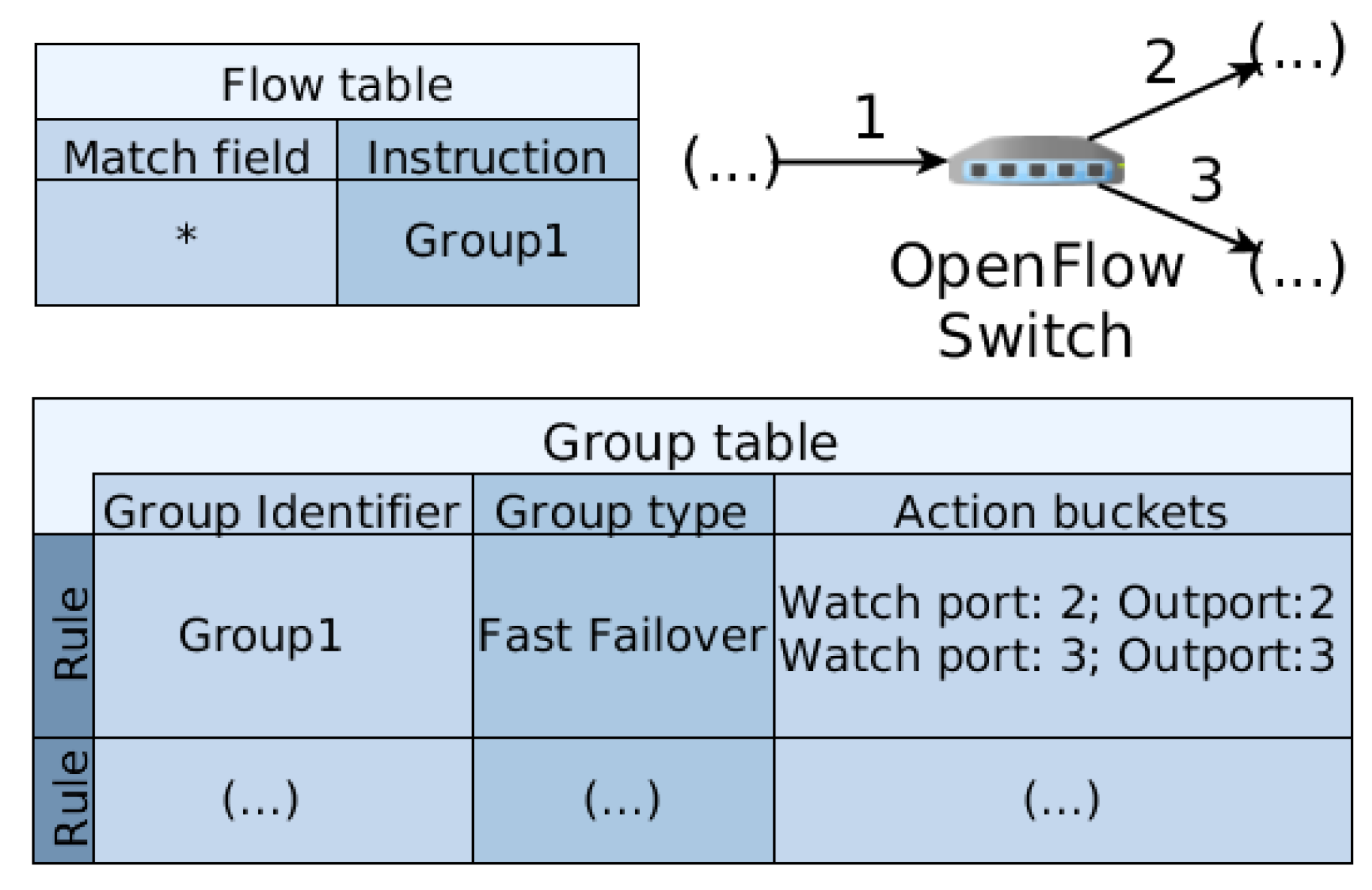
Figure 2 depicts a scheme for using FF. Suppose an OpenFlow switch has the flow table as indicated, in which the instruction of a flow is to apply the FF group type. Thus, the switch will autonomously monitor the first port in the action buckets, seeking for a change in the first watch port. If a link failure occurs with that network port interface, the status of the port will not have the bit OFPPS_LIVEenabled, and the switch will apply the next action in that action bucket. In the example of Figure 2, if port 2 goes down (caused by a failure), the switch stops forwarding traffic to port 2 and starts forwarding traffic to port 3. Whenever a link failure occurs, the controller must gain awareness about the underlying topology, as presented in the aforementioned Section 2.1.
3. Related Works
This section compiles and classifies a few recent works and approaches in the field of resilience mechanisms. It also presents the challenge of managing the number of rules required in a resilience mechanism, as the OpenFlow switches have a limited memory that can be used. This section concludes with a presentation of the state-of-the-art resilience schemes.
3.1. Classification of Resilience Mechanisms
A trade-off among rule installation and the signaling overhead between OpenFlow switches and the OpenFlow controller must be made [23,24]. Traditionally, the resilience mechanisms have been classified into two basic categories [17,18,25,26]: reactive approach (or restoration); and proactive approach (or protection).
Restoration solutions create rules on demand to react in the link failure events. Whenever a link failure occurs, the controller reacts by signaling the data plane elements to restore the broken flows affected by the failure. For OpenFlow networks, restoration solutions are similar to the usual process of flow creation. When a packet does not match any rule installed in an OpenFlow switch, often the switch enqueues the packet and informs the controller of a new flow creation via OFPT_PACKET_INmessages [19]. Afterward, the controller computes the rules to be associated with the new flow and installs them in the network. Once the rules are installed, on the switches, packets are dequeued and forwarded to the network. The freshly-installed rules will then process any subsequent packet of the flow without further intervention of the controller [18].
On the other hand, in a protection (or proactive) approach, rules are populated in advance, when backup paths are configured and installed before failures occur. In other words, a protected flow is created in the network before a failure occurs or any packet belonging to the primary path arrives at an OpenFlow switch port.
Instead of restoration and protection approaches, a third type in the classification of resilience mechanisms can be used, as well [23]. The active approach optimizes the control of network traffic, signaling and memory utilization by exploring the bird’s eye-view of SDN. This is reachable with the monitoring state of the network searching to mitigate the occurrence of a node/link failure. It is basically a hybrid of the proactive and reactive strategies. Therefore, this work describes and investigates LONG, a hybrid (or active) resilience mechanism to be deployed in OpenFlow networks.
3.2. Schemes of Resilience Mechanisms
In [27], the authors proposed a protection resilient mechanism against link and node failures to avoid disconnections between switches and controllers. They used pre-configured backup links in the switches, and when the communication failure occurs between the switch and the SDN controller, the switch can take local action by using the backup path to the controller. This local action does not need to involve other switches or the controller. Regarding disruption between OpenFlow switches, the authors in [14] proposed a restoration algorithm when link failures occur between OpenFlow switches.
The authors in [17] also presented a failover scheme for the protection of an individual link that connects two switches and used the Bidirectional Forwarding Detection (lBFD) [28] to detect the availability of network links. BFD works by sending control and echo messages between switches to discover the state of the connected links. Thus, they combined OpenvSwitch [29] (an OpenFlow switch implementation) with BFD and the OpenFlow Fast Failover group table [15] into a seamless solution. However, their scheme did not consider potential network traffic congestion when a failure occurs and flows need to use the backup paths, which may be already congested, making the situation even worse.
To improve the resilience mechanism of fast failover, the work in [30] applied t multiple backups paths for protection, called t-resilient. Thus, an SDN network operator could increase the number of alternative protect paths for a link between OpenFlow switches. Configuring multiple backup paths inside the OpenFlow switches has its drawbacks. OpenFlow switches often are deployed with Ternary Content Addressable Memory (TCAM). TCAM memories are very fast, however with the limitations of being high cost, because they require much space in their chip hardware, and having high energy consumption. Thereby, the appropriate use of rules is a fundamental approach for a practical SDN network operation.
Although having multiple protection paths seems to be intuitive for increasing the availability of the network, other works indicate that the probability of multiple links failing on a network over a single administrative domain is very low (e.g., a data center) [31,32]. Hence, a straightforward resilience mechanism for OpenFlow networks is to assume the scenario that only one link failure occurs at a given time.
The authors in [32] explore a failure recovery scheme using backup tunnels. The main idea of the work is to create a general optimization framework to model traffic engineering with backup tunnels and to be applicable for single link failures in an OpenFlow network. However, they delegate the distribution of bandwidth usage to the OpenFlow switches, using the group type Select of the OpenFlow specification. The problem with this approach is that the controller does not have awareness of the flow creation process in the network.
Finally, the compilation of the remaining related works is presented in Table 1, in which they are organized by the type of resilience mechanism, the main metrics used and the validation methodology adopted.
3.3. Resilience Mechanisms
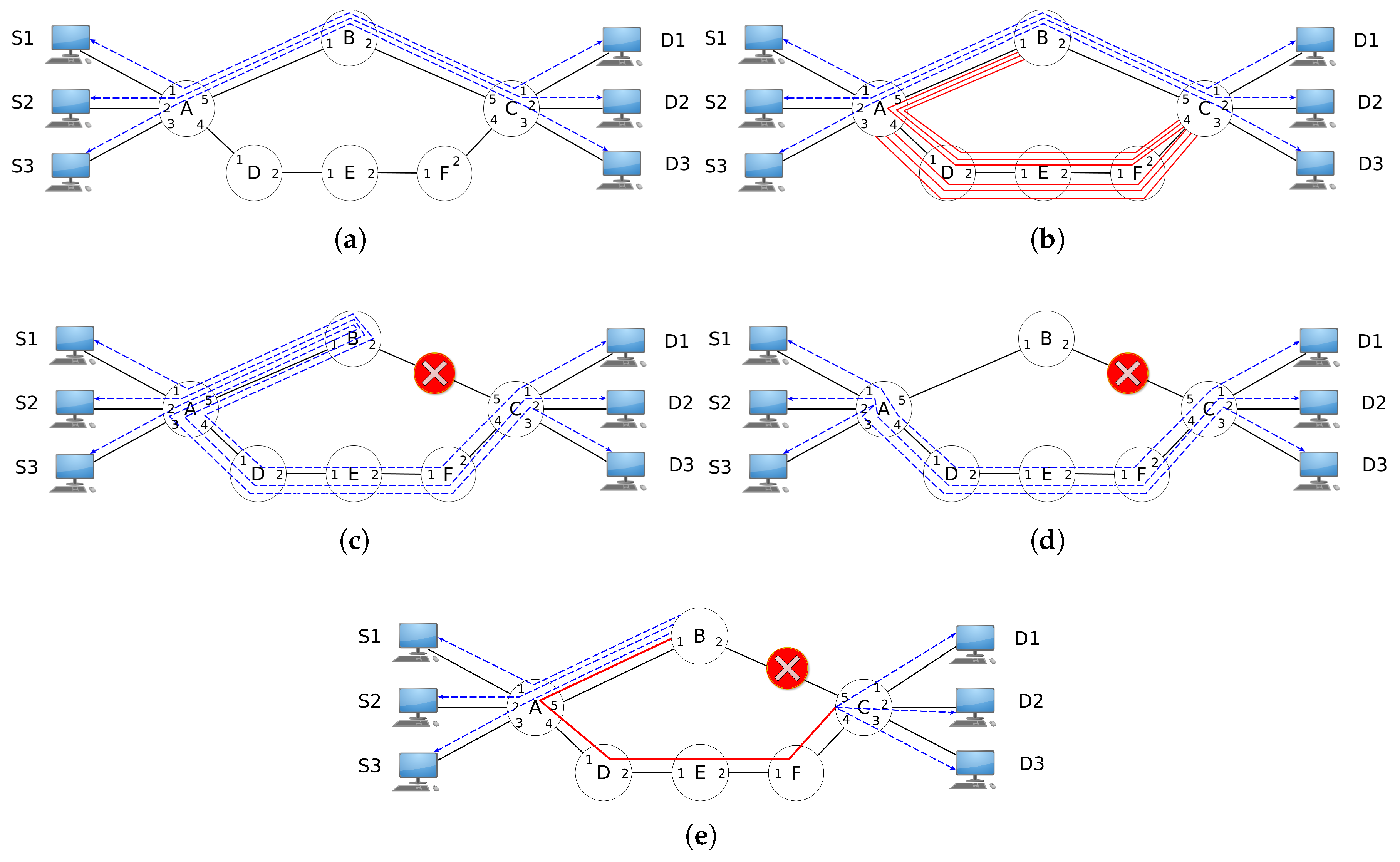
Figure 3 depicts the resilience mechanisms extracted from related works. Figure 3a describes an OpenFlow network with three primary flows from Sources (S1, S2, and S3) to Destination hosts (D1, D2 and D3). To protect the path [A, B, C], a resilience mechanism can create backup rules to avoid unavailability when a primary path suffers a link failure. In the case of the path [A, B, C], the affected link can be link A-B or B-C.
A trivial approach would be to instal OpenFlow rules to protect the link A-B and other rules to protect the flows from a link B-C failure. This logic is presented in Figure 3b, where the Path Protection (PP) applies OpenFlow rules to protect the path [A, B, C]. Thus, if link A-B or B-C suffers a failure, the flows from hosts S1, S2 and S3 still reach destination hosts D1, D2 and D3 by using the additional flows installed in advance for the protection scheme. Besides, no signaling between the controller and OpenFlow switches is needed. Nonetheless, extra rules are required to compose an operational solution (as indicated by the paths [B, A, D, E, F, C] and [A, D, E, F, C] in Figure 3b).
Instead of the protection mechanism, a network operator can opt for a restoration approach, where new flows are installed after failure. Figure 3c depicts the operation of Local Restoration (LR). LR is indicated when the computation path time is a bottleneck of the resilience scheme to restore the flows (network with a considerable number of nodes and links). Thus, when a link failure occurs, the OpenFlow controller acquires the information of what nodes have evolved and reconstructs the broken path between those nodes. If the packets belong to the affected flows, they need to be sent back through the same input port of an OpenFlow switch; the OpenFlow specification has a special port for this case. The OFPP_IN_PORT is a virtual port that has to be explicitly set in OpenFlow rules in order for a switch send a packet back to the same input port [19].
Another restoration mechanism is Path Restoration (PR) (see Figure 3d), which the work of Sharma et al. [14] uses. Different from LR, PR exercises the global view of SDN networks and computes the best path (often using the shortest path algorithm) for each flow affected by the broken link. Note that under certain circumstances, LR and PR can produce the same outcome. In the topology used as the example (see Figure 3a), if link A-B suffers a failure, the recovery mechanism of LR and PR will produce the same final network state because Node A is the disjoint point between the primary and backup path.
To reduce signaling between controller and OpenFlow switches, as well as the number of flow entries installed, a resilience recovery strategy can employ an aggregation scheme. The aggregation scheme can use the IP network mask or tunnels. The application of Local Fast Restoration (LFR) is presented in Figure 3e. Thus, instead of treating every flow individually (as PP and PR), LFR aggregates all flows into one “big” flow that makes all packets affected by the failure be redirected using this “big” flow. An example of work that applies the LFR concept is in Zhang et al. [13].
4. Local Group Node Fast Reroute
This section presents the Local Group Node fast reroute (LONG). LONG is a hybrid approach of resilience mechanisms for OpenFlow networks that has two phases. In the first phase, a given path is protected by the additional OpenFlow rules with FF (see Section 2.2 for more information). When a link (or a set of links) fails, LONG applies the second phase, which restores the consistency state of the network and optimizes all paths affected by the link failure. The next subsection presents an example that explains and clarifies the phases of LONG.
4.1. An Example
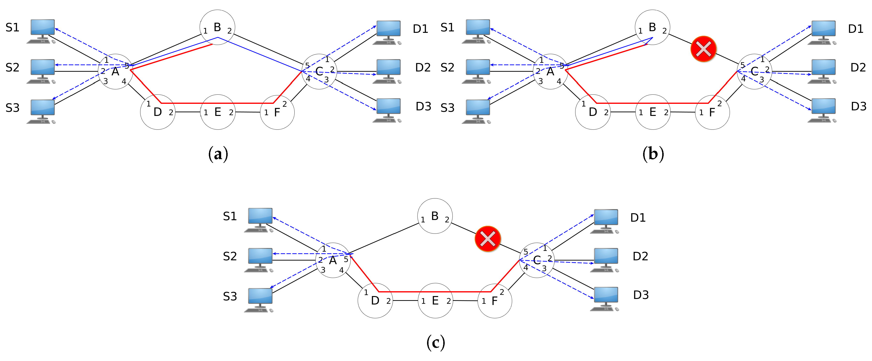
The application of LONG in a simple topology is depicted in Figure 4, in which the source hosts (S1, S2 and S3) communicate with each destination host (D1, D2 and D3). In Figure 4a, the path [A, B, C] is the primary path for flows from source to destination hosts. LONG applies a protection rule from Node B to Node C (path [B, A, D, E, F]). Thus, if any of the links A-B or B-C suffers a failure, the backup path will be used automatically with the OpenFlow feature of FF. That way, path [A, B, C] is protected.
If a link that belongs to the primary path suffers a failure, the protected path will be used, as indicated by Figure 4b, in which the link B-C is no longer available. As a consequence, the packets traveling through a backup path will reach Node C (destine node). Thus, even if the link A-B fails, all the flows from source hosts will continue to experience reachability to destination hosts because the backup path also protects that link. This is the basic idea of LONG’s protection phase, where the main goal is to make the paths highly available.
Nonetheless, the use of a backup path can result in a non-optimal network utilization because it is possible that the flows will travel a longer distance than necessary after a link failure. A restoration phase is fundamental to make all the paths optimal again. Often, the shortest path algorithm is used to create optimal paths (in which the path length is the metric), but an optimal path can be defined with any metric that a network operator stipulates.
A resilience mechanism deployed in the network hardware, such as FF, can lead to an inconsistent global view of the network because when a link failure occurs, all multiplex actions of FF are performed inside the OpenFlow switch without the consent of the controller [11]. In this situation, the controller must recover the current network state.
Different from previous works that adopted specific protocols for discovering a link failure (e.g., BFD [28]), LONG uses the OpenFlow messages OFPT_PORT_STATUS sent by OpenFlow switches to the controller. Those messages contain the identification of the switch and port affected by the failure. Therefore, the controller acquires information necessary to recover the network state consistency and perform corrections to non-optimized flows.
Once the controller is aware of the a link failure, it starts a restoration phase to recover the consistency of the network state and makes flows that are using backup paths optimal again. Figure 4c presents the scheme for the restoration of the path between Nodes A and C, after the link B-C failure. That concludes LONG’s final phase.
4.2. Notation and Concepts
For brevity, first, the notation used throughout this work is summarized in Table 2, and an individual description for each item is provided. The notation is used to compose the LONG algorithms, and those are detailed in the next subsections.
Thus, before delving into the algorithms, some concepts need to be defined. One of them is the concept of endpoints. They are places inside an OpenFlow network where the network operator has some interest for packets to reach that location (notation O; see Table 2). An endpoint can be a host, a switch port connected to a load balancer appliance, the ingress/egress of the backbone network, and so forth. Thus, an endpoint consists of two elements. The first one is the source, where the packets are identified to belong a specific flow, and the destination, the place where the packets are released from the flow. Furthermore, the path connecting the source to the destination is composed using a tunnel.
This work models an OpenFlow network as a directed graph (or digraph) , where V is a set of nodes (e.g., OpenFlow switches) and E a set of edges (e.g., network links). For the creation of the network state, the OpenFlow controller usually uses flood messages to discover the topology and maintain the graph data structure, . Thereby, with the topology of the OpenFlow network known, the flow creation algorithms can be applied, once the OpenFlow controller has an instance of the data structure of G. One way to reach that topology information is fetching OpenFlow switches with control packets to discover the origin and destiny of the links, switches and hosts (as already described in Section 2.1).
4.3. LONG Protection Phase
The protection phase of LONG is responsible for distributing the primary and backup paths through the network. Algorithm 1 depicts the protection phase of LONG, where it is assumed that the network topology is known, the set of endpoints and a set of path identifiers is provided.
Between lines 1 and 7, the primary path is computed using Dijkstra’s algorithm (line 2). Afterwards, a unique identification for primary and backup paths is reserved from the set of identifiers (lines 3 and 4), and that identification is assigned to be installed for primary and backup paths (lines 5 and 6).
| Algorithm 1 The algorithm of LONG for the protection phase. |
| Input: The network topology , set of endpoints O, set of identifiers I. Output: For all endpoints, install primary and backup paths between source and destination.
|
For installation of the primary path, Algorithm 2 is used. The algorithm requires the network topology, the identifier selected for the primary path, the switches that compose the endpoints and the path between those endpoints. Lines 2–5 initialize the variables, and then the installation of the primary path occurs between lines 6 and 12.
| Algorithm 2 Install primary path. |
| Input: The network topology , an identifier i, switch source , switch destination , path from to Output: Install a primary path between switch source and switch destination using the selected identifier.
|
Algorithm 3 installs the backup paths for the primary path. The idea here is proactive install rules that avoid any unavailability in the primary path.
| Algorithm 3 Install backup paths. |
| Input: The network topology , an identifier i, switch source , switch destination , path from to Output: Install backup paths between switch source and switch destination using the selected tag.
|
4.4. LONG Restoration Phase
After the LONG protection phase, the LONG resilience mechanism begins the restoration phase. Algorithm 4 depicts the restoration phase of the LONG approach. This phase is important to avoid the underutilization of flow entries in the OpenFlow network. Thereby, the algorithm uses the packet with the information of the link failure. Between lines 1–5, the involved switches are identified, the topology is updated with the failed link, and the affected flows are discovered.
Then, once the current network state is known, then new paths for the affected flows can be installed. Lines from 6–10 depict this process for each flow affected by the link failure.
| Algorithm 4 The algorithm of LONG for the restoration phase. |
| Input: The network topology , set of F, set of identifiers I and . Output: The flows will follow the shortest path.
|
5. Evaluation
For performance evaluation, LONG is analyzed against the PP, LR, PR and LFR approaches. PP is a protection resilience mechanism (that creates backup rules in advance), and LR, PR and LFR are restoration approaches (see Section 3.3 for more detail about those resilience mechanisms). The description of those algorithms, as well as the literature reviewed are in Section 3.
Two computers were used to emulate the OpenFlow network scenarios. The first computer was a dedicated machine with Ubuntu Version 17.04, 8 CPU cores with a clock of 2.20 GHz and 8 GB of RAM. This computer was used as the OpenFlow controller with Ryu [34]. The second computer has Ubuntu Version 14.04.4 with 3 GB of RAM and a dual-core CPU with a 2.4-GHz clock. This second machine executed Mininet [35] for the network emulation environment. A physical Ethernet cable of 100 Mbps connected the computers in crossover mode.
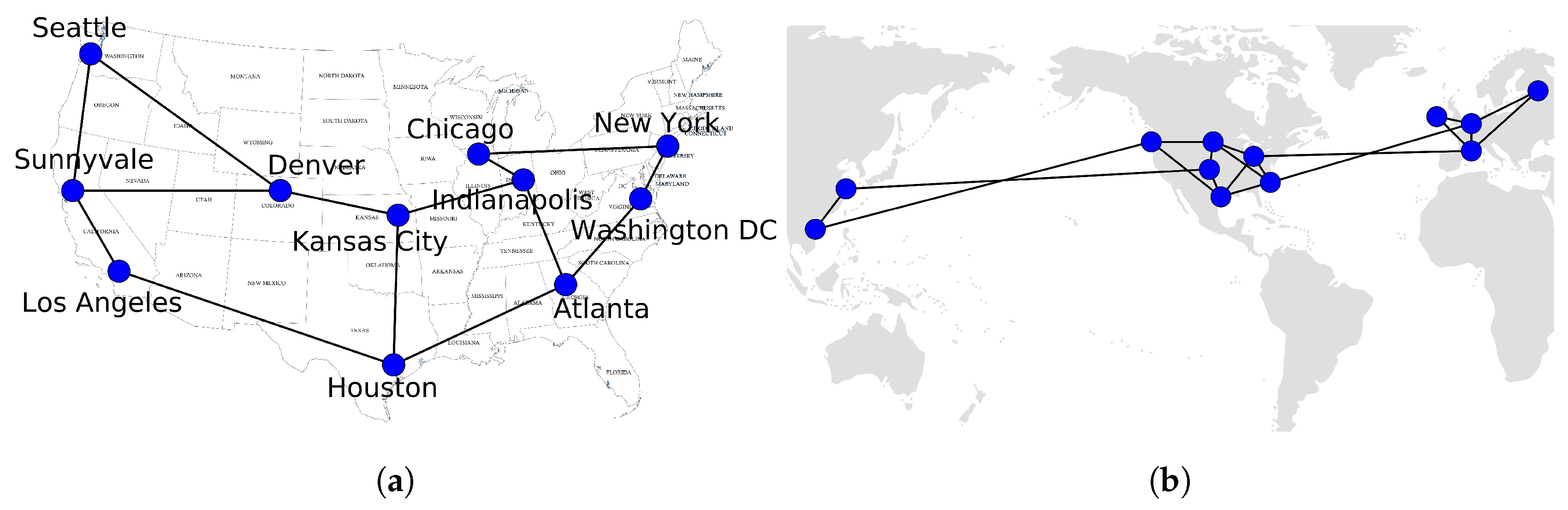
The dataset topology from Internet Topology Zoo [36] was used. Topology Zoo is an ongoing project that collects network topologies’ information from around the world, and it is very useful for researchers to access information from real-world topologies. The 2005’ Abilene topology was adopted to apply the experiments of LONG. Once, with the data network information, the network topology was reproduced inside the emulation environment of Mininet [35]. The topology used has 11 nodes and 14 links. Figure 5a presents the Abilene topology representation.
Besides the Abilene topology, another topology adopted was from the WAN Google topology. The Google topology was extracted from the work of [37]. It was composed of 12 nodes and 18 links, and its representation is in Figure 5b. Therefore, all topologies adopted in this work are in Figure 5.
5.1. Flows Entries
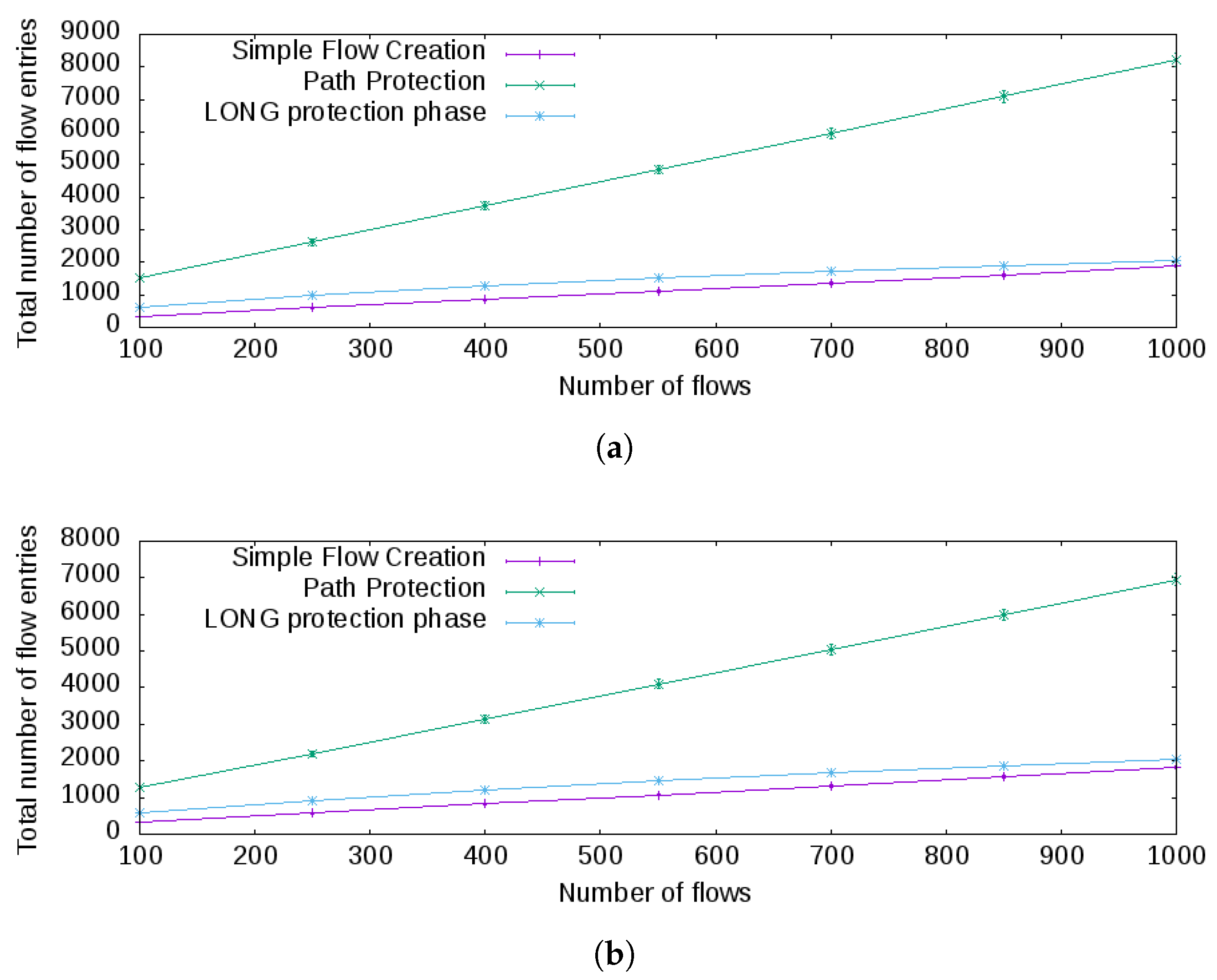
A criterion for measurement scalability is using the number of messages as an evaluation metric [38]. Thus, one way to evaluate LONG is using the total number of possible flow entries required for connecting two endpoints in the OpenFlow network. The flow entries can be understood as the rules used in the flow table of an OpenFlow switch. Thereby, the flow entries consumed for the approaches measured were: simple flow creation (where a flow connects to endpoints in the topology); path protection; and LONG protection phase (for details about the last two approaches, see Section 4.3).
Two endpoints were randomly selected in one of the topologies and the number of flow entries in each experiment executed measured more than 300 times, then the average was computed. Besides, for the Abilene and Google topologies, each experiment was configured as 10 flows per path to connect the two endpoints. In other words, a path connecting two endpoints will have 10 flows. After collecting the measurements, the average and standard deviation were calculated, and a confidence interval of 95% was used. The results for the Abilene and Google topologies are in Figure 6.
The baseline for analysis is the simple flow creation. This algorithm uses one flow entry in each OpenFlow switch for every flow created in the path between the endpoints. Compared against path protection, path protection consumes much more flow entries on average to connect the endpoints in both topologies; see Figure 6a,b, respectively. This result is expected, as for each flow, a protection path must be created, as well, and that protection path avoids the unavailability of the flow in the presence of a link failure.
However, with the LONG protection phase, the average number of flow entries is a little bit higher than simple flow creation. This difference is caused by the additional use of flow entries to represent the backup tunnel paths required to protect the main path of each flow. Compared to path protection, the LONG protection phase is a more scalable solution based on the results achieved and the topologies adopted because it will consume the least number of flows on average.
5.2. Signaling Overhead
Protection approaches install primary and backup flow entries in advance to prevent connectivity interruptions. After a link failure, no signaling messages between OpenFlow switches and the controller are sent to restore connectivity. This is true if and only if the rules use FF (or other hardware-based resilience solution). Otherwise, the number of signaling messages between switches and the controller is the number of flow entries affected by the failure, because it is necessary to change the forward port number for every flow entry affected by the failed link.
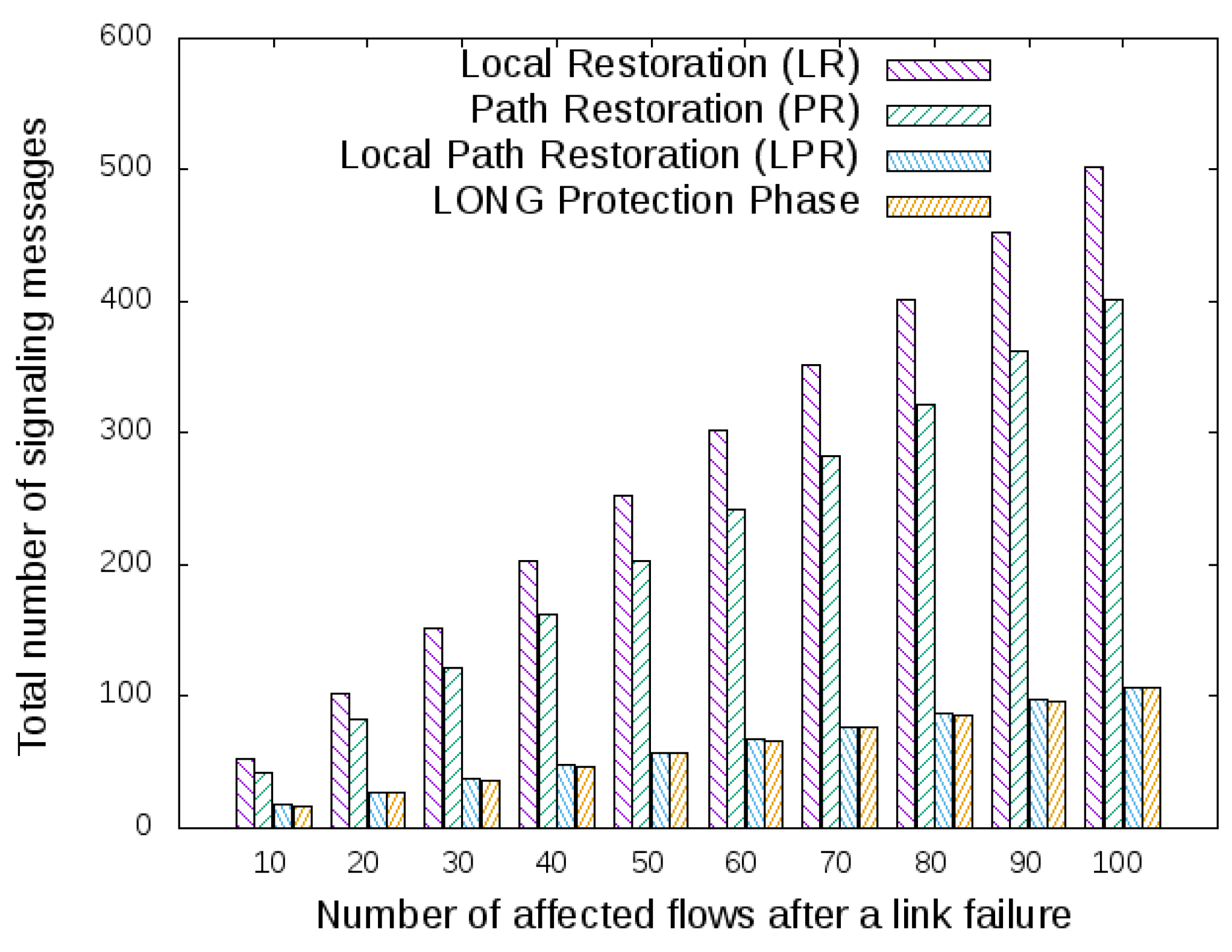
Hence, it is mandatory to investigate the signaling overhead of restoration approaches. Those are analyzed using scenarios that describe a link’s failure occurring in one of the topologies adopted. Thereby, the Abilene topology depicted in Figure 5a will be used, and the following resilience mechanisms will be compared: Local Restoration (LR), Path Restoration (PR), Local Path Restoration (LPR) and LONG protection phase.
Suppose that in the topology adopted (Abilene topology; see Figure 5a), the primary path is made through the cities of Seattle, Sunnyvale, Los Angeles and Houston. Suddenly, the link connecting Los Angeles and Houston suffers a failure. The number of affected flows and the total number of signaling messages to recover from that failure are depicted in Figure 7. Regarding the LR and PR approaches and based on the achieved data, PR generates fewer signaling messages to the SDN controller than LR. This outcome is the opposite of the results presented in the work of Zhang et al. [13], where LR generated a lesser number of update flow entries. The justification for this result is that the LR may not be the shortest path between two given endpoints.
Thereby, when a link in the path between two endpoints suffers a failure, if the shortest path from the OpenFlow switches’ source and the destination of the failed link does not belong to the shortest path between the endpoints, then LR will require more signaling messages than PR. The reason for this signaling overhead is that there are more OpenFlow switches to restore the network connectivity after a link failure. Besides, LR and PR produce much more signaling messages with a relative lesser number of affected flows after a link failure, as a typical link requires hundreds of thousands of flows per link (e.g., in the Internet Exchange Point (IXP) environment [39]).
Regarding LPR and LONG, they notoriously overcome LR and PR for signaling overhead criteria (see Figure 7). The LPR signaling to OpenFlow switches belongs to a new path, and the LONG restoration phase sends control messages for the affected OpenFlow switches to restore the optimal shortest paths of the flows between endpoints. Then, based on the results achieved, LPR and LONG are almost equivalent among the signals sent to the controller.
5.3. Failure Recovery Time
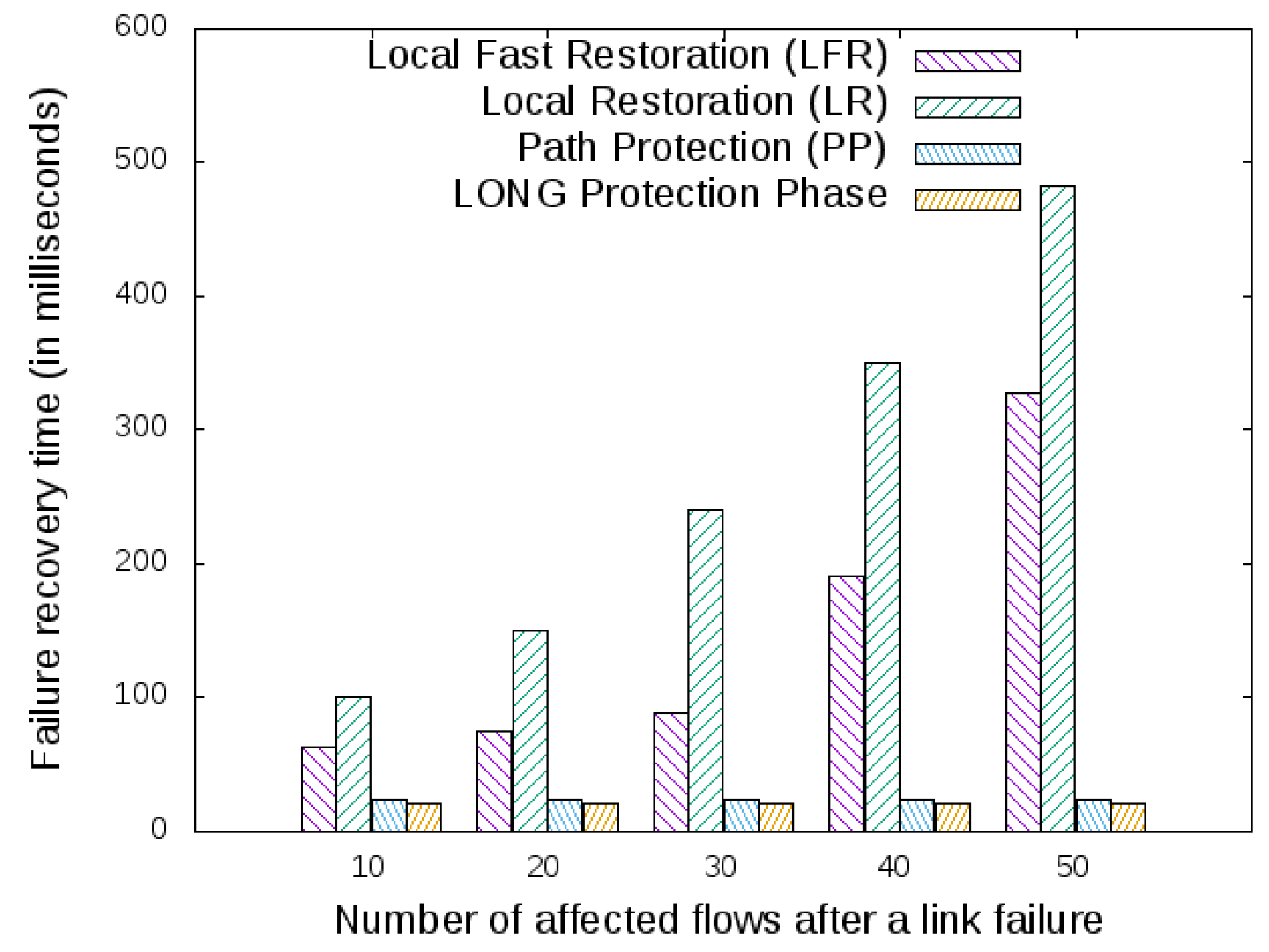
For the sake of space, two restoration and two protection resilience mechanisms were selected to investigate the metric failure recovery time. For the restoration approach, Local Fast Restoration (LFR) and Local Restoration (LR) were used. Both restoration approaches require signaling to the SDN controller to recover from a link failure. However, this is not the case for the protection mechanisms, which is the case of path protection and the LONG protection phase, as all recovery rules are already installed inside the OpenFlow switches, and those rules protect the network from a link failure.
To execute the experiments, a subset of the Abilene topology (depicted in Figure 5a) was used. Using the iperf [40] tool, a different number of flows from the node Sunnyvale (of Figure 5a) to the node Houston was generated, making the primary path composed of the nodes Sunnyvale, Los Angeles and Houston. Because this work uses the number of hops as the main metric to define what is a better path, the backup path is composed by the nodes Sunnyvale, Denver, Kansas City and Houston. Then, the link connecting Los Angeles and Houston suffers a failure, and for each resilience mechanism, the results of the failure recovery time are measured and plotted in Figure 8.
Figure 8 shows the failure recovery time, where the x-axis represents the number of disrupted traffic flows and the y-axis the failure recovery time in milliseconds for each resilience mechanism. As expected, the restoration approaches take more time to recover the flows, because a communication between the OpenFlow switch and the controller is required. However, LFR reduces the restoration time against LR because it aggregates all the affected flows into one “big” flow, using the backup path. LR recovers each flow individually, and hence, that behavior affects the recovery time.
Analyzing the protection approaches, because PP and the LONG protection phase already had installed the backup path using the FF, when a link failure was detected by the OpenFlow switch, then it automatically switched the primary path to the backup path. As a consequence, the recovery time becomes minimal. However, the number of flow entries required by the PP approaches is higher than the LONG protection phase (see Figure 6a), and that factor increases the lookup time of the OpenFlow switch table, affecting the failure recovery time of the flows for the PP.
6. Further Discussion
LONG assumes that the network operator planned the backup paths to not suffer congestion when those are required. This is one limitation of the LONG approach. It does not have a congestion control mechanism after a link failure. The authors in [33] described a mechanism to avoid the congestion situation proactively by spreading backup paths to settle k faults in an arbitrary network topology (congestion control with protected approach). In addition, the work of [16] presented a restoration approach to mitigate traffic congestion called the switchover mechanism. It changes flows from one OpenFlow switch to another when the bandwidth of a backup link surpasses a given threshold (congestion control with restoration approach).
In the work [13], the authors used one aggregation strategy, tagging VLANand aggregate flows with the same source and destination to avoid the creation of each flow individually. However, this aggregation only occurs after a link disruption. This could lead to packets being lost during the computation of the restoration phase. LONG already places backup paths for the data plane elements to taking independent actions without requiring consulting the controller.
Furthermore, previous works approach the rule placement problem [18] as a static problem that has to be optimized. However, the behavior and dynamics of the flows inside an SDN network were not captured as desired. Thus, a stateful proposal was made for that problem using two phases to compose the LONG approach. Additionally, because LONG uses the path to restore flows, it does not matter if a set of links or switches becomes unavailable, as LONG algorithm will repair those broken flows. Hence, LONG can be used when OpenFlow switches have to enter maintenance mode [41].
Regarding reducing the number of flow entries, Palette [42] and One Big Switch [43] are works that seek to optimize the number of flow entries. They are proposals that tried to address the OpenFlow switches’ memory limitation. They considered that the rules to be installed are non-reducible, so they cannot enforce rule aggregations. Thus, the solutions distributed the routing rules in the network in such a way that the routing semantics are maintained and the network policies are not violated.
The work of [44] also seeks to optimize the placement of routing rules within an SDN network. It accomplishes this by minimizing the resources required for the treatment of network flows. With an algebraic model and using the integer linear programming optimization technique to express constraints in the end-to-end routing policy on the network, the work indicated how to allocate a greater amount of traffic over memory capacity constraints using the model proposed. The work also performs comparisons with the solutions Palette and One Big Switch and found similar values of optimization. However, it overcomes the previous works in a scenario of extreme memory shortage, when the SDN controller must be triggered to maintain the minimum network operating state, even if network performance degradation occurs.
When compression [18] strategies can be applied, the reduction of flow entries is made, keeping the forwarding logic (or semantics) intact. Those strategies are possible because OpenFlow rules can use wildcards to match packet header fields, such as IP addresses. The authors in [45] used a five-element tuple consisting of TCP/IP header fields (source IP, destination IP, transport layer protocol, TCP port and TCP port of the destination) with aggregation of those fields to mitigate the number of flow entries in the inter-domain routing system.
An aggregation can also be done to reduce the number of flows entries. For fast rerouting inside an SDN network, the work [13] used VLAN tags in the strategy to aggregate different flows to contour paths that passed through failure links. This approach avoids the limitation of OpenFlow match fields that cannot use a wildcard, such as transportation ports (for example, TCP or UDP ports); however, there is a limited number of VLAN tags that can be used (maximum of 4096 possible values).
7. Conclusions
Based on the achieved results, this work concluded that LONG is a practical hybrid resilience mechanism for OpenFlow networks. In the protected phase, LONG provides a reasonable number of flow entries (OpenFlow rules) to protect the network against failed links, when compared with simple flow creation and path protection. Furthermore, during the restoration phase of LONG, it is equivalent to the local path restoration approach regarding signaling messages between OpenFlow switches and the controller.
Funding
This research received no external funding.
Conflicts of Interest
The author declares no conflict of interest.
References
- Singh, S.; Jha, R.K. A Survey on Software Defined Networking: Architecture for Next Generation Network. J. Netw. Syst. Manag. 2017, 25, 321–374. [Google Scholar] [CrossRef]
- Nunes, B.A.A.; Mendonca, M.; Nguyen, X.N.; Obraczka, K.; Turletti, T. A survey of software-defined networking: Past, present, and future of programmable networks. IEEE Commun. Surv. Tutor. 2014, 16, 1617–1634. [Google Scholar] [CrossRef]
- Silva, W.J.A. An Architecture to Manage Incoming Traffic of Inter-Domain Routing Using OpenFlow Networks. Information 2018, 9, 92. [Google Scholar] [CrossRef]
- Silva, W.J.A.; Sadok, D.F.H. Control Inbound Traffic: Evolving the Control Plane Routing System with Software Defined Networking. In Proceedings of the 18th International Conference on High Performance Switching and Routing (HPSR), Campinas, Brazil, 18–21 June 2017. [Google Scholar]
- Kreutz, D.; Ramos, F.M.V.; Veríssimo, P.E.; Rothenberg, C.E.; Azodolmolky, S.; Uhlig, S. Software-Defined Networking: A Comprehensive Survey. Proc. IEEE 2015, 103, 14–76. [Google Scholar] [CrossRef] [Green Version]
- Silva, W.J.A.; Sadok, D.F.H. A Survey on Efforts to Evolve the Control Plane of Inter-Domain Routing. Information 2018, 9, 125. [Google Scholar] [CrossRef]
- Feamster, N.; Rexford, J.; Zegura, E. The road to SDN: An Intellectual History of Programmable Networks. ACM SIGCOMM Comput. Commun. Rev. 2014, 44, 87–98. [Google Scholar] [CrossRef]
- McKeown, N.; Anderson, T.; Balakrishnan, H.; Parulkar, G.; Peterson, L.; Rexford, J.; Shenker, S.; Turner, J. OpenFlow: Enabling Innovation in Campus Networks. ACM SIGCOMM Comput. Commun. Rev. 2008, 38, 69. [Google Scholar] [CrossRef]
- Sharma, S.; Staessens, D.; Colle, D.; Palma, D.; Goncalves, J.; Figueiredo, R.; Morris, D.; Pickavet, M.; Demeester, P. Implementing Quality of Service for the Software Defined Networking Enabled Future Internet. In Proceedings of the 2014 Third European Workshop on Software Defined Networks, London, UK, 1–3 September 2014; pp. 49–54. [Google Scholar]
- Vishnoi, A.; Poddar, R.; Mann, V.; Bhattacharya, S. Effective Switch Memory Management in OpenFlow Networks. In Proceedings of the 8th ACM International Conference on Distributed Event-Based Systems, Mumbai, India, 26–29 May 2014. [Google Scholar]
- Silva, W.J.A. Avoiding Inconsistency in OpenFlow Stateful Applications Caused by Multiple Flow Requests. In Proceedings of the International Conference on Computing, Networking and Communications (ICNC), Maui, HI, USA, 5–8 March 2018; pp. 543–548. [Google Scholar]
- Rothenberg, C.E.; Nascimento, M.R.; Salvador, M.R.; Corrêa, C.N.A.; Cunha de Lucena, S.; Raszuk, R. Revisiting routing control platforms with the eyes and muscles of software-defined networking. In Proceedings of the First Workshop on Hot Topics in Software Defined Networks, Helsinki, Finland, 13 August 2012; p. 13. [Google Scholar]
- Zhang, X.; Cheng, Z.; Lin, R.; He, L.; Yu, S.; Luo, H. Local Fast Reroute with Flow Aggregation in Software Defined Networks. IEEE Commun. Lett. 2016, 7798, 1–4. [Google Scholar] [CrossRef]
- Sharma, S.; Staessens, D.; Colle, D.; Pickavet, M.; Demeester, P. Enabling Fast Failure Recovery in OpenFlow Networks. In Proceedings of the 2011 8th International Workshop on the Design of Reliable Communication Networks (DRCN), Krakow, Poland, 10–12 October 2011; pp. 164–171. [Google Scholar]
- Pfaff, B.; Lantz, B.; Heller, B.; Barker, C.; Cohn, D.; Talayco, D.; Erickson, D.; Crabbe, E.; Gibb, G.; Appenzeller, G.; et al. OpenFlow 1.1 Specification; Open Networking Foundation: Menlo Park, CA, USA, 2011; pp. 1–56. [Google Scholar]
- Lin, Y.D.; Teng, H.Y.; Hsu, C.R.; Liao, C.C.; Lai, Y.C. Fast failover and switchover for link failures and congestion in software defined networks. In Proceedings of the 2016 IEEE International Conference on Communications, ICC 2016, Kuala Lumpur, Malaysia, 22–27 May 2016. [Google Scholar]
- Adrichem, N.L.V.; Asten, B.J.V.; Kuipers, F.A. Fast Recovery in Software-Defined Networks. In Proceedings of the 2014 3rd European Workshop on Software Defined Networks, London, UK, 1–3 September 2014; pp. 61–66. [Google Scholar]
- Nguyen, X.N.; Saucez, D.; Barakat, C.; Turletti, T. Rules Placement Problem in OpenFlow Networks: A Survey. IEEE Commun. Surv. Tutor. 2016, 18, 1273–1286. [Google Scholar] [CrossRef]
- Pfaff, B.; Lantz, B.; Heller, B.; Barker, C.; Cohn, D.; Casado, M. OpenFlow Switch Specification—1.3 Version; Open Networking Foundation: Menlo Park, CA, USA, 2012. [Google Scholar]
- Katz, D.; Ward, D. BFD for IPv4 and IPv6 Single Hop. arXiv, 2010; arXiv:1011.1669v3. [Google Scholar]
- Cascone, C.; Pollini, L.; Sanvito, D.; Capone, A.; Sanso, B. SPIDER: Fault resilient SDN pipeline with recovery delay guarantees. In Proceedings of the IEEE NETSOFT 2016 IEEE NetSoft Conference and Workshops, Software-Defined Infrastructure for Networks, Clouds, IoT and Services, Seoul, Korea, 6–10 June 2016; pp. 295–302. [Google Scholar]
- Bianchi, G.; Bonola, M.; Capone, A.; Cascone, C. OpenState: Programming Platform-independent Stateful OpenFlow Applications Inside the Switch. ACM SIGCOMM Comput. Commun. Rev. 2014, 44, 44–51. [Google Scholar] [CrossRef]
- Silva, W.J.A. Performance Evaluation of Flow Creation Inside an OpenFlow Network. In Proceedings of the XXXV Simpósio Brasileiro de Telecomunicações e Processamento de Sinais—SBrT2017, São Pedro, SP, Brazil, 3–6 September 2017; pp. 102–106. [Google Scholar]
- Silva, W.J.A.; Dias, K.L.; Sadok, D.F.H. A Performance Evaluation of Software Defined Networking Load Balancers Implementations. In Proceedings of the International Conference on Information Networking (ICOIN), Da Nang, Vietnam, 11–13 January 2017. [Google Scholar]
- Fernandez, M.P. Comparing OpenFlow controller paradigms scalability: Reactive and proactive. In Proceedings of the International Conference on Advanced Information Networking and Applications, AINA, Barcelona, Spain, 25–28 March 2013; pp. 1009–1016. [Google Scholar]
- Akyildiz, I.F.; Lee, A.; Wang, P.; Luo, M.; Chou, W. A roadmap for traffic engineering in software defined networks. Comput. Netw. 2014, 71, 1–30. [Google Scholar] [CrossRef]
- Beheshti, N.; Zhang, Y. Fast Failover for Control Traffic in Software-defined Networks. In Proceedings of the 2012 IEEE Global Communications Conference (GLOBECOM), Anaheim, CA, USA, 3–7 December 2012; pp. 2665–2670. [Google Scholar]
- Katz, D.; Ward, D. Bidirectional Forwarding Detection. J. Phys. A Math. Theor. 2010, 53, 160. [Google Scholar]
- OpenvSwitch. Open vSwitch. 2016. Available online: http://openvswitch.org/ (accessed on 13 June 2018).
- Stephens, B.; Cox, A.L.; Rixner, S. Scalable Multi-Failure Fast Failover via Forwarding Table Compression. In Proceedings of the Symposium on SDN Research, Santa Clara, CA, USA, 14–15 March 2016; pp. 1–12. [Google Scholar]
- Gill, P.; Jain, N.; Nagappan, N. Understanding network failures in data centers. ACM SIGCOMM Comput. Commun. Rev. 2011, 41, 350. [Google Scholar] [CrossRef]
- Zheng, J.; Xu, H.; Zhu, X.; Chen, G.; Geng, Y. We’ve got you covered: Failure recovery with backup tunnels in traffic engineering. In Proceedings of the 2016 IEEE 24th International Conference on Network Protocols (ICNP), Singapore, 8–11 November 2016; pp. 1–10. [Google Scholar]
- Liu, H.H.; Kandula, S.; Mahajan, R.; Zhang, M.; Gelernter, D. Traffic Engineering with Forward Fault Correction. In Proceedings of the 2014 ACM Conference on SIGCOMM, Chicago, IL, USA, 17–22 August 2014; pp. 527–538. [Google Scholar]
- Ryu. A Component-Based Software Defined Networking Framework—Ryu. 2016. Available online: https://osrg.github.io/ryu/ (accessed on 13 June 2018).
- Mininet. Mininet—An Instant Virtual Network on Your Laptop (Or Other PC). Available online: https://github.com/mininet/mininet (accessed on 13 June 2018).
- Topology-zoo. The internet topology zoo. IEEE J. Sele. Areas Commun. 2017, 29, 1765–1775. [Google Scholar]
- Jain, S.; Zhu, M.; Zolla, J.; Hölzle, U.; Stuart, S.; Vahdat, A.; Kumar, A.; Mandal, S.; Ong, J.; Poutievski, L.; et al. B4: experience with a globally-deployed software defined wan. In Proceedings of the ACM SIGCOMM 2013 Conference on SIGCOMM, Hong Kong, China, 12–16 August 2013; p. 3. [Google Scholar]
- Mendiola, A.; Astorga, J.; Jacob, E.; Higuero, M. A Survey on the Contributions of Software-Defined Networking to Traffic Engineering. IEEE Commun. Surv. Tutor. 2017, 19, 918–953. [Google Scholar] [CrossRef]
- Gupta, A.; MacDavid, R.; Birkner, R.; Canini, M.; Feamster, N.; Rexford, J.; Vanbever, L. An Industrial-Scale Software Defined Internet Exchange Point. In Proceedings of the 13th USENIX Symposium on Networked Systems Design and Implementation (NSDI 16), Santa Clara, CA, USA, 16–18 March 2016; pp. 1–14. [Google Scholar]
- Iperf. Iperf-Perform Network Throughput Tests. 2016. Available online: http://iperf.sourceforge.net/ (accessed on 13 June 2018).
- Fonseca, P.; Mota, E. A Survey on Fault Management in Software-Defined Networks. IEEE Commun. Surv. Tutor. 2017, 19, 2284–2321. [Google Scholar] [CrossRef]
- Kanizo, Y.; Hay, D.; Keslassy, I. Palette: Distributing tables in software-defined networks. In Proceedings of the IEEE INFOCOM, Turin, Italy, 14–19 April 2013; pp. 545–549. [Google Scholar]
- Kang, N.; Liu, Z.; Rexford, J.; Walker, D. Optimizing the “one big switch” abstraction in software-defined networks. In Proceedings of the 9th ACM Conference on Emerging Networking Experiments and Technologies, Santa Barbara, CA, USA, 9–12 December 2013; pp. 13–24. [Google Scholar]
- Nguyen, X.N.; Saucez, D.; Barakat, C.; Turletti, T.; Sophia, I.; Méditerranée, A. Optimizing Rules Placement in OpenFlow Networks: Trading Routing for Better Efficiency. In Proceedings of the Third Workshop on Hot Topics in Software Defined Networking, Chicago, IL, USA, 22 August 2014; pp. 127–132. [Google Scholar]
- Wang, Y.; Bi, J.; Lin, P.; Lin, Y.; Zhang, K. SDI: A multi-domain SDN mechanism for fine-grained inter-domain routing. Ann. Telecommun. 2016, 71, 625–637. [Google Scholar] [CrossRef]
Figure 1.
Topology discovery using flood messages.

Figure 2.
Scheme of the fast failover.

Figure 3.
Examples of resilience mechanisms for OpenFlow networks. (a) Flows created from and to nodes; (b) additional rules of Path Protection (PP); (c) after link B-C failure and application of Local Restoration (LR); (d) after link B-C failure and application of Path Restoration (PR); (e) after link B-C failure and application of Local Fast Restoration (LFR).

Figure 4.
LONG dynamics before and after a link failure. (a) LONG before the link B-C failure. Path [A, B, C] is protected. (b) LONG after the link B-C failure (proactive protection). (c) LONG after the protection and restoration phases are applied.
Figure 4.
LONG dynamics before and after a link failure. (a) LONG before the link B-C failure. Path [A, B, C] is protected. (b) LONG after the link B-C failure (proactive protection). (c) LONG after the protection and restoration phases are applied.

Figure 5.
Topologies adopted in this work. (a) The representation of the Abilene topology. (b) The representation of a WAN Google topology.
Figure 5.
Topologies adopted in this work. (a) The representation of the Abilene topology. (b) The representation of a WAN Google topology.

Figure 6.
Number of flow entries for different topologies. (a) To the Abilene topology, the number of flow entries for each approach adopting 10 flows per path. (b) The number of flow entries for each approach with 10 flows per path using the Google topology.
Figure 6.
Number of flow entries for different topologies. (a) To the Abilene topology, the number of flow entries for each approach adopting 10 flows per path. (b) The number of flow entries for each approach with 10 flows per path using the Google topology.

Figure 7.
Results for the signaling overhead after a link failure in different scenarios of the Abilene topology.
Figure 7.
Results for the signaling overhead after a link failure in different scenarios of the Abilene topology.

Figure 8.
Results for failure recovery time after a link failure in the Abilene topology.


Table 1.
A comparison of related works with regards to type (restoration or protection), main metric (depends on each work) and validation methodology (simulation, emulation or prototype). TCAM, Ternary Content Addressable Memory; LONG, Local Node Group fast reroute.
Table 1.
A comparison of related works with regards to type (restoration or protection), main metric (depends on each work) and validation methodology (simulation, emulation or prototype). TCAM, Ternary Content Addressable Memory; LONG, Local Node Group fast reroute.
| Works | Type | Main Metrics | Validation |
|---|---|---|---|
| Sharma et al. [14] | Restoration | Switchover time, round-trip time and packet loss | Emulation and simulation |
| Beheshti and Zhang [27] | Protection | Unprotectability | Simulation |
| Liu et al. [33] | Protection | Data loss and throughput | Emulation |
| Adrichem et al. [17] | Protection | Recovery time | Prototype |
| Stephens, Cox and Rixner [30] | Protection | TCAM utilization | Simulation |
| Lin et al. [16] | Protection | Flow entries, packet loss and average recovery time | Emulation |
| Cascone et al. [21] | Restoration | Packet loss and flow entries | Emulation and simulation |
| Zhang et al. [13] | Restoration | Flow entries and failure recovery time | Emulation |
| LONG | Restoration and protection | Packet loss, memory utilization, and recovery time | Emulation and simulation |
Table 2.
Notation adopted.
| Notation | Description |
|---|---|
| The network topology, where V denotes the set of nodes (switches) and E the set of edges (links between switches) | |
| O | Set of endpoints (source and destination of a flow) |
| I | A set of path identifiers |
| s | Source endpoint (source a flow) |
| d | Destination endpoint (destination a flow) |
| Function that returns the output port for destination d of switch v | |
| Function that returns the match for a given argument | |
| OpenFlow packet port status event | |
| OpenFlow packet output event | |
| Function that sends an packet. | |
| F | All flows installed and active in the network. |
| v | An OpenFlow switch |
| l | A failed link |
| Provides the number of elements in a given set |
© 2018 by the author. Licensee MDPI, Basel, Switzerland. This article is an open access article distributed under the terms and conditions of the Creative Commons Attribution (CC BY) license (http://creativecommons.org/licenses/by/4.0/).
Share and Cite
MDPI and ACS Style
Silva, W.J.A. Make Flows Great Again: A Hybrid Resilience Mechanism for OpenFlow Networks. Information 2018, 9, 146. https://doi.org/10.3390/info9060146
AMA Style
Silva WJA. Make Flows Great Again: A Hybrid Resilience Mechanism for OpenFlow Networks. Information. 2018; 9(6):146. https://doi.org/10.3390/info9060146
Chicago/Turabian StyleSilva, Walber José Adriano. 2018. "Make Flows Great Again: A Hybrid Resilience Mechanism for OpenFlow Networks" Information 9, no. 6: 146. https://doi.org/10.3390/info9060146
Note that from the first issue of 2016, this journal uses article numbers instead of page numbers. See further details here.