Article

Evaluation of Soil-Structure Interaction on the Seismic Response of Liquid Storage Tanks under Earthquake Ground Motions

by
Mostafa Farajian
1,
Mohammad Iman Khodakarami
1,* and
Denise-Penelope N. Kontoni
2,*
1
Faculty of Civil Engineering, Semnan University, Semnan, 35131-19111, Iran
2
Department of Civil Engineering, Technological Educational Institute of Western Greece, GR-26334 Patras, Greece
*
Authors to whom correspondence should be addressed.
Computation 2017, 5(1), 17; https://doi.org/10.3390/computation5010017
Submission received: 1 December 2016 / Revised: 15 February 2017 / Accepted: 9 March 2017 / Published: 12 March 2017

Abstract

:
Soil-structure interaction (SSI) could affect the seismic response of structures. Since liquid storage tanks are vital structures and must continue their operation under severe earthquakes, their seismic behavior should be studied. Accordingly, the seismic response of two types of steel liquid storage tanks (namely, broad and slender, with aspect ratios of height to radius equal to 0.6 and 1.85) founded on half-space soil is scrutinized under different earthquake ground motions. For a better comparison, the six considered ground motions are classified, based on their pulse-like characteristics, into two groups, named far and near fault ground motions. To model the liquid storage tanks, the simplified mass-spring model is used and the liquid is modeled as two lumped masses known as sloshing and impulsive, and the interaction of fluid and structure is considered using two coupled springs and dashpots. The SSI effect, also, is considered using a coupled spring and dashpot. Additionally, four types of soils are used to consider a wide variety of soil properties. To this end, after deriving the equations of motion, MATLAB programming is employed to obtain the time history responses. Results show that although the SSI effect leads to a decrease in the impulsive displacement, overturning moment, and normalized base shear, the sloshing (or convective) displacement is not affected by such effects due to its long period.

1. Introduction

Liquid storage tanks are important structures which have a key role in human lives. The major existing codes, regulations, guidelines, and recommendations—such as API (650, 620), AWWA (D100, D103, D110, D115), Eurocode 8 Part 4 (and Eurocode 3), UNI EN 14015, Covenin, IITK, ACI (350.3, 371.R), NZSEE, AIJ—for the seismic design of tanks are widely used, although, in some cases, the codes were not correctly applied or there are imperfections in the code requirements. These structures have shown poor performance and failure modes during strong earthquakes—such as overturning, buckling, roof damage, sliding, uplift, different settlement, etc., which may also cause liquid leakage and fire after an earthquake—as described, for example, in [1,2,3,4].
It is clear that, in designing of such structures, all factors that affect seismic responses of these structures should be considered. One of these factors is soil-structure-interaction (SSI). The SSI affects earthquake ground motions, characteristics of structures, and also soil properties. Accordingly, depending on the period of structure, the seismic response of structure could either increase or decrease. Several studies showed that the SSI effect is more important for massive structures such as tall buildings, bridges, and liquid storage tanks which could cause to suspend their performance [5,
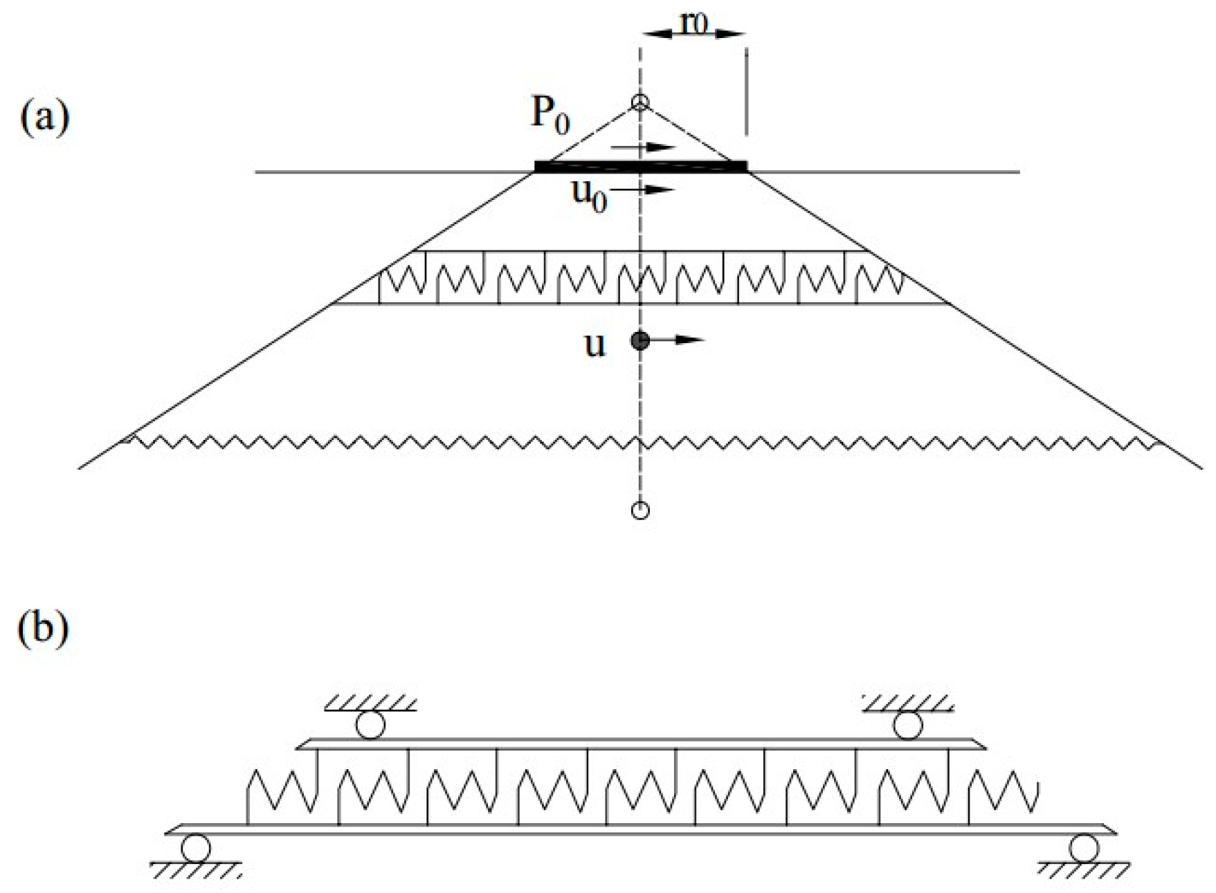
6]. The most popular and relatively accurate model to represent the soil-structure-interaction is the substructure method which considers the soil as coupled springs and dashpots [7,8].
Liquid storage tanks behave differently from common structures, such as buildings, bridges, etc., due to fluid-structure-interaction. Housner’s mass-spring model [7] was the first approximate model to obtain the seismic responses of rigid cylindrical liquid storage tanks. In Housner’s model [7], the whole liquid is divided into two parts; a portion of liquid which excites independently of the tank wall near the free surface is named as “convective” and the other part of liquid exciting unison with the tank wall is named “impulsive”. By increasing the tank’s geometry (i.e., radius and height), Haroun and Housner [8] modified the Housner’s model to consider the flexibility of the tank’s wall; in their presented model, the liquid is divided into three portions; convective and impulsive masses which are attached to the tank’s wall through springs and dashpots and the rigid mass which is attached to the tank’s wall rigidly. Malhotra et al. [9] have proposed a simplified model by considering higher modes of impulsive mass with the first impulsive modal mass and higher mode of convective mass with the first convective modal mass. Bagheri et al. [10] studied the seismic responses of liquid storage tanks under near-fault ground motions; such earthquake ground motions have long-period components that may affect the long-period sloshing motion of liquid [10]. The effect of earthquake characteristics on seismic responses of base isolated liquid storage tanks is also studied by Bagheri and Farajian [11], who showed that the pulse-like earthquake-ground motions could cause excessive displacement in base isolation and, therefore, the impact could occur.
The SSI effect on the seismic response of liquid storage tanks has been studied by several researchers, mostly in the frequency domain. Veletsos and Tang [12] proposed a method to consider the SSI; they proposed to modify the impulsive mass frequency and damping to consider the SSI effect and their research has shown that the SSI has no special effect on convective mass displacement. Larkin [13] obtained the responses of steel and concrete liquid storage tanks considering SSI effect, and found that SSI affects the shear force and overturning moment, especially on soft soils. Foundation embedment effects on the behavior of elevated tanks were studied by Livaoglu and Dogangun [14], who concluded that embedment in soft soil significantly affects the tank roof’s displacement. Livaoglu [15] shown that decreasing the stiffness of the soil leads to reduction of the base shear and impulsive displacement; on the other hand, sloshing displacement is not considerably affected due to SSI, embedment, and wall flexibility [15].
In this paper, the effect of SSI on the seismic response of liquid storage tanks is studied under earthquake ground motions in the time domain. Accordingly, after solving the equations of motion in the time domain, the peak responses are obtained and compared with the ones without considering SSI.

2. Structural Model of the Fluid-Tank-Soil System

A simplified model is implemented here to model the fluid-tank-soil interaction. Figure 1 shows a cylindrical liquid storage tank rested on a half space soil. As modeling of the interaction effects is complicated, the theory of Malhotra et al. [9] is used to consider the fluid-structure-interaction (FSI), and the cone method [16] is employed to the simulation of soil-structure-interaction (SSI) effects. These models have been briefly described below.

2.1. Fluid-Tank System

The 3D finite element model of a liquid storage tank is usually complicated due to hydrodynamic interaction effects. Accordingly, the simplified mass-spring model of Malhotra et al. [9] is used in the present study. The geometry of a cylindrical tank is the liquid height (H), the tank’s radius (r), and the equivalent uniform thickness of the tank wall (t), as shown in Figure 2. According to Figure 3, the convective and impulsive masses (mc and mi) are connected to the tank’s wall by springs and dashpots (kc and cc, ki and ci). The natural periods of the convective (Tc) and impulsive (Ti) of responses are [9]:
T c = C c r
T i = C i H ρ s E . t / r
where, ρs and E are the mass density of liquid and modulus of elasticity of the tank’s wall, respectively. The coefficients Cc and Ci, the relative convective and impulsive masses (mc/m and mi/m) and heights (hc/H and hi/H) are provided by Malhotra et al. [9]. The total liquid mass of the tank filling with water is equal to (πr2w). The corresponding stiffness and damping ratio of springs and dashpots associated with convective and impulsive masses are equal to:
k c = m c × ω c 2
k i = m i × ω i 2
c c = 2 ξ c m c × ω c
c i = 2 ξ i m i × ω i
where ωc and ωi are the frequency of convective and impulsive responses. The damping ratio of the convective and impulsive modes (ξc and ξi) are 0.5% and 2%, respectively.

2.2. Soil-Structure System

Considering real conditions, a liquid storage tank resting on soil consists of a tank (structure) and an adjacent bounded soil called near-field soil and unbounded soil called far-field. Both near-field and far-field soils affect the seismic response of the structure.
The soil-structure-interaction could be modeled using three proposed methods: (i) the direct method by employing numerical methods, such as the finite element method (FEM), boundary element method (BEM), and scaled boundary-finite element method (SBFEM); (ii) modifying the fixed base condition to take into account of SSI, where, in this model the effect of foundation embedment, layering, and material damping was ignored; and (iii) the substructure method which considers the soil by either dependent or independent frequency springs and dashpots which could be either used in the time or frequency domains. In order to obtain the corresponding stiffness and damping, three methods could be used: (i) the procedures presented in NIST GCR 12-917-21 [17]; (ii) the thin layer method which is used by SASSI software [18]; and (iii) the cone method proposed by Meek and Wolf [16]. Compared to other numerical methods, the cone model [16] has a simple numerical procedure and relative accurate response. In the cone method, the soil is modeled using springs and dashpots, and cones have translational, rotational, and torsional behavior. Only the translational motion is considered in this paper due to its simplicity, and remaining motions are ignored.
Based on the cone method theory, when a homogenous semi-infinite domain is subjected to a static load (P0), the components of the displacement field will vary along the depth in the shape of a truncated cone, as shown in Figure 4, for the horizontal translational degree of freedom. The static stiffness of this truncated cone in a circular rigid foundation and equivalent circular foundation can be expressed by [19]:
K S t a t i c = 8 ρ v s 2 r 0 2 υ
where, ρ and vs are mass density and shear velocity of the soil medium, r0 is the radius of the equivalent circular foundation and υ is the Poisson’s ratio. For dynamic problems, the stiffness of the half-space in the cone model is frequency dependent and this static stiffness is used for calculating the dynamic stiffness S(a0) which is expressed by:
S ( a 0 ) = K ( k ( a 0 ) + i a 0 c ( a 0 ) )
where k(a0) is the dynamic spring coefficient, c(a0) is the dynamic damping coefficient, and a0 is the dimensionless frequency equaled to ωr0/vs with implementing excitation frequency ω. In this study, these frequency dependent stiffness and damping coefficients are calculated using CONAN computer program.
In order to investigate the response of the structure due to various earthquakes on different soil conditions, four types of soil are considered, where, these soil properties are mentioned in Table 1; as it is clear from this table, soil S1 is known as a hard rock and by going to S4, the soils change to softer soil. As described, the cone method and CONAN program are used to evaluate the impedance functions of these four soil types by employing the soil characteristics.

2.3. Governing Equations of Motion

The equations of motion of the system of simplified model of liquid storage tank considering the SSI effect, as shown in Figure 5, can be written as:
m c u ¨ c + c c ( u ˙ c u ˙ f ) + k c ( u c u f ) = m c u ¨ g
m i u ¨ i + c i ( u ˙ i u ˙ f ) + k i ( u i u f ) = m i u ¨ g
m f u ¨ f + c c ( u ˙ f u ˙ c ) + c i ( u ˙ f u ˙ i ) + c s u ˙ f + k c ( u f u c ) + k i ( u f u c ) + k s u f = m i u ¨ g
where uc, ui, and uf are convective, impulsive, and foundation displacements relative to the bedrock, respectively, and üg is the earthquake ground motion. The foundation mass is also represented by mf. Other parameters are described in Section 2.1.
Using state-space method, a MATLAB (MathWorks Inc., Natick, MA, USA) routine is provided to solve the governing equations of motion. The numerical results will be mainly presented in terms of the convective and impulsive displacements relative to the foundation (xc, xi) according to Equations (12) and (13), free vertical surface displacement (dx) according to Equation (14), and the overturning moment (OM) and structural base shear (Fs) according to Equations (15) and (16). The overturning moment and base shear are normalized by weight of the system:
x c = u c u f
x i = u i u f
d x = 0.837 R ω c 2 ( u c u f ) g
O M = k c × x c × h c + c c × v c × h c + k i × x i × h i + c i × v i × h i
F s = k c × x c + c c × v c + k i × x i + c i × v i

3. Numerical Study

A parametric study has been done to evaluate the effect of SSI. For this purpose, a broad and a slender steel tank have both been considered as a numerical study. The resulting seismic responses of the tanks are compared with those of fixed ones. The geometric properties of the tank models are summarized in Table 2 and the resultant parameters of the equivalent mechanical models are listed in Table 3. The characteristics of selected earthquake ground motion records for time history analyses are tabulated in Table 4 and the six selected ground motions are classified, into two groups, namely far fault (no. 1, 3, 5) and near fault (no. 2, 4, 6) ground motions. The considered earthquake records are obtained from the web-based PEER ground motion database [20]. The selected near-fault ground motions have been recorded close to faults and have revealed near-fault pulses, while the selected far-fault ground motions have been recorded far from faults and have revealed far-fault pulses.

4. Results

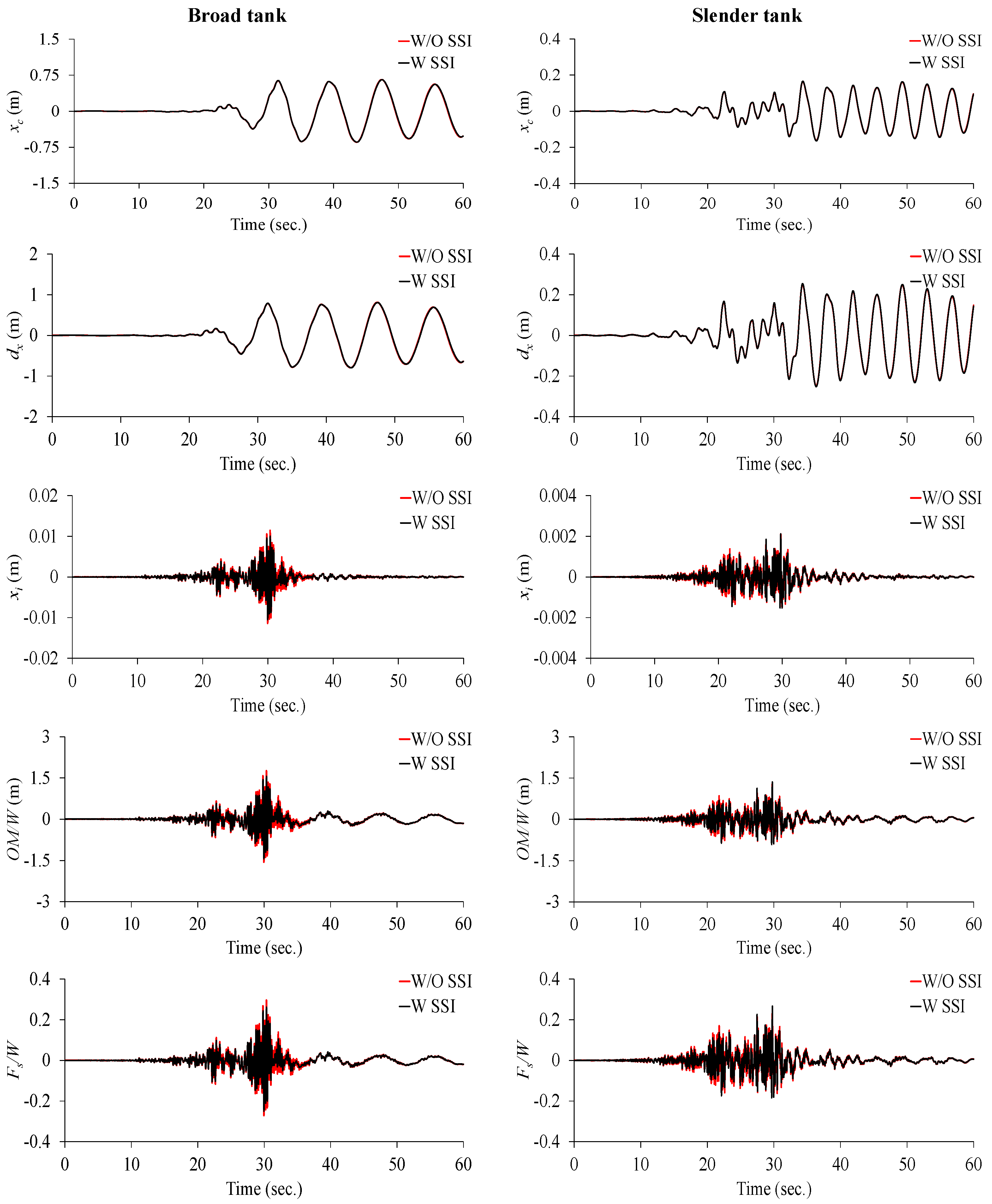
In this section, the effect of SSI on seismic responses of both broad and slender liquid storage tanks is studied. For example, Figure 6 depicts the time history of considered responses of two broad and slender tanks mounted on soil type 4 under Chichi-NST-E ground motion in both without SSI and with SSI, respectively.
The peak responses of broad and slender tanks rested on various soil types under different ground motions are tabulated in Table 5, Table 6, Table 7, Table 8, Table 9, Table 10, Table 11 and Table 12.
It is observed that the impulsive mass displacement, normalized overturning moment and normalized base shear are reduced due to SSI effect. SSI causes a shift in the period of the structure; therefore, the responses get reduced. Such reduction will lead to better performance of these structures during earthquake events. On the other hand, the convective mass displacement is slightly affected. This phenomenon is related to the fact that the convective response has a relatively long period and, therefore, the SSI has no special effect on this response.
From Table 5, Table 6, Table 7, Table 8, Table 9, Table 10, Table 11 and Table 12, it is observed that the maximum values obtained for the reduction percentage of impulsive mass displacement, normalized overturning moment and normalized base shear are 13.2%, 20.3%, and 20.7% for broad tank under Chichi-NST-E ground motion, and 20%, 19.1%, and 22.5% for slender tank under Chichi-TCU075-W earthquake, when the liquid storage tank rested on soil type 4 (see Table 11 record no. 1 and Table 12 record no. 2). From all the data of Table 5, Table 6, Table 7, Table 8, Table 9, Table 10, Table 11 and Table 12 (for the six selected earthquake ground motions), 
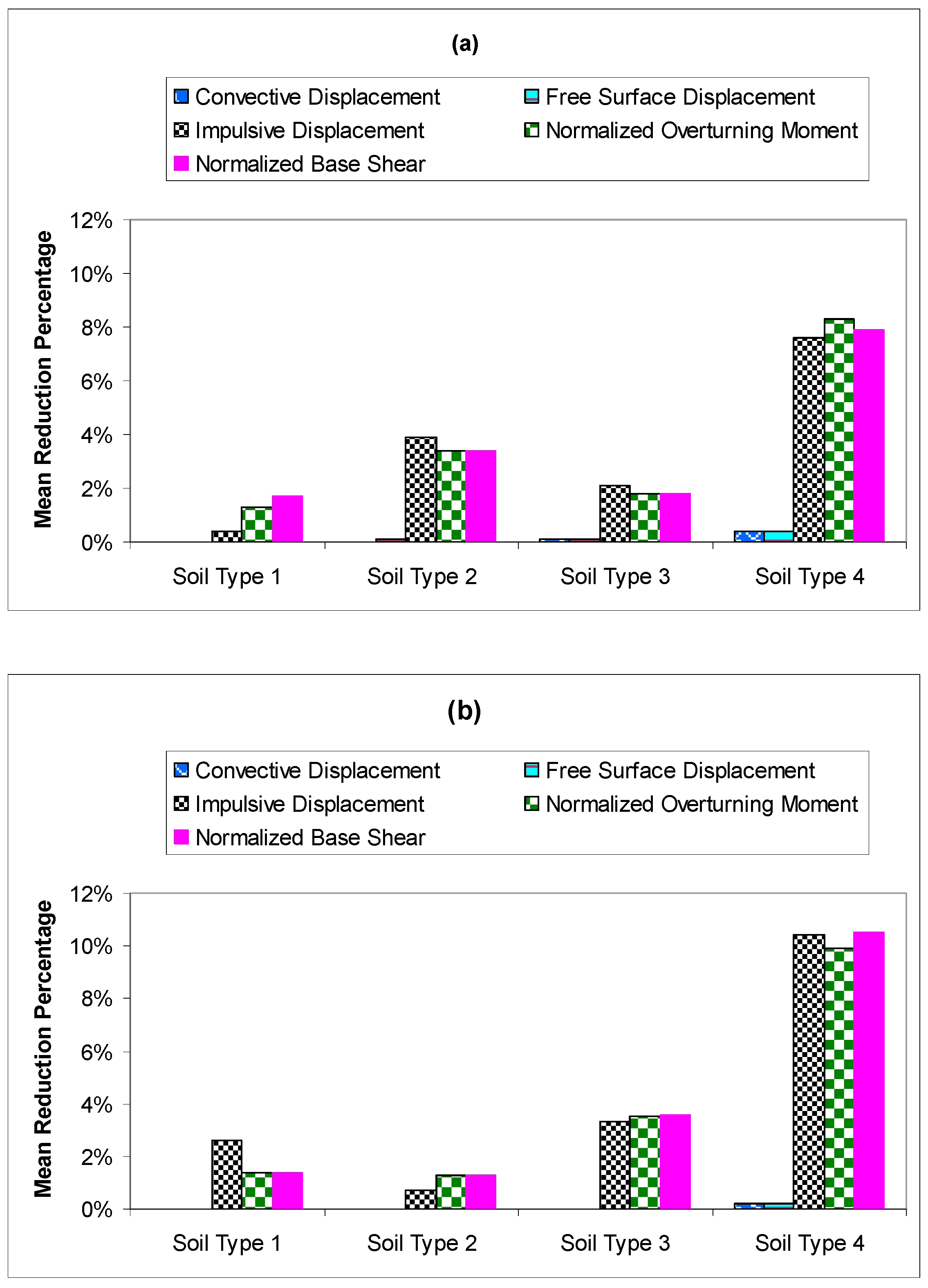
Figure 7 shows the mean reduction percentages of peak responses in broad and slender tank due to SSI effect (where for the calculation of each mean reduction percentage, in those only very few specific cases in which there is amplification and not reduction because of the frequency content of the earthquake and the structure, those reduction percentages are taken as negative). Generally, as the shear velocity of medium soil decreases, the aforementioned responses reduce further. The mean reduction percentages of impulsive mass displacement, normalized overturning moment, and normalized base shear are 7.6%, 8.3%, and 7.9% for broad tank, and 10.4%, 9.9%, and 10.5% for slender tank, when the liquid storage tank rested on soil type 4. According to Figure 7, the convective mass displacement and also free vertical surface displacement is only slightly reduced. This is due to long period of convective mass. However, for soil type 4, the SSI causes to reduce the convective mass displacement and also free vertical surface displacement, compared to the without SSI condition. This phenomenon is observed in both broad and slender tanks.

5. Conclusions

The seismic behavior of liquid storage tanks, considering the SSI effect, is evaluated in this paper. The substructure method is used to consider the SSI effect, and dynamic stiffness and damping are obtained using the cone method. Two types of tanks rested on four soil types are considered as the case study. Then the peak responses of these tanks, in both with and without considering SSI, under six earthquake excitations are compared. According to obtained responses, the impulsive mass displacement, normalized overturning moment, and normalized base shear are reduced as the SSI effect is considered. However, for relatively stiff soil, this reduction is not considerable but, for soft soil, the SSI effect could shift the fundamental period of impulsive mass and, therefore, the impulsive displacement and other dependent responses reduce.
Since convective mass has a long period, the SSI did not considerably affect its seismic characteristics. Nevertheless, the transition from relatively stiff soil (S1) to softer soil (S4) could cause a shift in the fundamental period of the spectrum and, therefore, the convective displacement is also reduced.

Author Contributions

Mostafa Farajian contributed to preparing the computer codes, performing the analysis, and preparing the first draft of the manuscript. Mohammad Iman Khodakarami contributed to checking the formulations and technical concepts of the research and also finalizing the results. Denise-Penelope N. Kontoni contributed to the writing and finalizing of this paper and also the reviewing process of this research.

Conflicts of Interest

The authors declare no conflict of interest.

References

  1. Manos, G.C. Evaluation of the earthquake performance of anchored wine tanks during the San Juan, Argentina, 1977 earthquake. Earthq. Eng. Struct. Dyn. 1991, 20, 1099–1114. [Google Scholar] [CrossRef]
  2. Cooper, T.W. A Study of the Performance of Petroleum Storage Tanks during Earthquakes, 1933–1995; Report for US Department of Commerce: NIST GCR 97-720; US Department of Commerce: Gaithersburg, MD, USA, 1997.
  3. Zareian, F.; Sampere, C.; Sandoval, V.; McCormick, D.L.; Moehle, J.; Leon, R. Reconnaissance of the Chilean Wine Industry Affected by the 2010 Chile Offshore Maule Earthquake. Earthq. Spectra 2012, 28, S503–S512. [Google Scholar] [CrossRef]
  4. Brunesi, E.; Nascimbene, R.; Pagani, M.; Beilic, D. Seismic performance of storage steel tanks during the May 2012 Emilia, Italy, Earthquakes. J. Perform. Constr. Facil. (ASCE) 2015, 29, 04014137. [Google Scholar] [CrossRef]
  5. Halabian, A.M.; El Naggar, M.H. Effect of non-linear soil–structure interaction on seismic response of tall slender structures. Soil Dyn. Earthq. Eng. 2002, 22, 639–658. [Google Scholar] [CrossRef]
  6. Stewart, J.P.; Fenves, G.L.; Seed, R.B. Seismic soil-structure interaction in buildings. I: Analytical methods. J. Geotech. Geoenviron. Eng. 1999, 125, 26–37. [Google Scholar] [CrossRef]
  7. Housner, G.W. Dynamic pressures on accelerated fluid containers. Bull. Seismol. Soc. Am. 1957, 47, 15–35. [Google Scholar]
  8. Haroun, M.A.; Housner, G.W. Seismic design of liquid storage tanks. J. Tech. Counc. ASCE 1981, 107, 191–207. [Google Scholar]
  9. Malhotra, P.K.; Wenk, T.; Wieland, M. Simple procedure for seismic analysis of liquid-storage tanks. Struct. Eng. Int. 2000, 10, 197–201. [Google Scholar] [CrossRef]
  10. Bagheri, S.; Rofooei, F.; Bozorgnia, Y. Evaluation of the seismic response of liquid storage tanks. In Proceedings of the 10th International Conference on Civil, Structural and Environmental Engineering Computing, Rome, Italy, 30 August–2 September 2005; Topping, B.H.V., Ed.; Civil-Comp Press: Stirling, UK; Paper No. 216.
  11. Bagheri, S.; Farajian, M. The effects of input earthquake characteristics on the nonlinear dynamic behavior of fps isolated liquid storage tanks. J. Vib. Control 2016. [Google Scholar] [CrossRef]
  12. Veletsos, A.S.; Tang, Y. Soil-structure interaction effects for laterally excited liquid storage tanks. Earthq. Eng. Struct. Dyn. 1990, 19, 473–496. [Google Scholar] [CrossRef]
  13. Larkin, T. Seismic response of liquid storage tanks incorporating soil structure interaction. J. Geotech. Geoenviron. Eng. 2008, 134, 1804–1814. [Google Scholar] [CrossRef]
  14. Livaoglu, R.; Dogangun, A. Effect of foundation embedment on seismic behavior of elevated tanks considering fluid–structure-soil interaction. Soil Dyn. Earthq. Eng. 2007, 27, 855–863. [Google Scholar] [CrossRef]
  15. Livaoglu, R. Investigation of seismic behavior of fluid–rectangular tank–soil/foundation systems in frequency domain. Soil Dyn. Earthq. Eng. 2008, 28, 132–146. [Google Scholar] [CrossRef]
  16. Meek, J.W.; Wolf, J.P. Cone models for homogeneous soil. I. J. Geotech. Eng. 1992, 118, 667–685. [Google Scholar] [CrossRef]
  17. NEHRP Consultants Joint Venture, Soil-Structure Interaction for Building Structures; NIST GCR 12-917-21; NIST (National Institute of Standards and Technology), U.S. Department of Commerce: Gaithersburg, MD, USA, 2012.
  18. Lysmer, J.; Tabatabaie-Raissi, M.; Tajirian, F.; Vahdani, S.; Ostadan, F. SASSI: A System for Analysis of Soil-Structure Interaction; Report No. UCB/GT/81/02; Department of Civil Engineering, University of California: Berkeley, CA, USA, 1981. [Google Scholar]
  19. Wolf, J.P.; Deeks, A.J. Foundation Vibration Analysis: A Strength of Materials Approach; Butterworth-Heinemann: Oxford, UK, 2004. [Google Scholar]
  20. PEER Ground Motion Database, Pacific Earthquake Engineering Research Centre. Available online: http://ngawest2.berkeley.edu (accessed on 2 January 2016).
Figure 1. Liquid storage tank resting on a half space.
Computation 05 00017 g001
Figure 2. Geometry of the liquid storage tank.
Computation 05 00017 g002
Figure 3. Simplified mass-spring model of Malhotra for fluid-structure-interaction.
Computation 05 00017 g003
Figure 4. Translational truncated semi-infinite cone with horizontal motion, shear distortion and equilibrium of infinitesimal element, where rocking motion is prevented with: (a) infinite flexural rigidity; and (b) rollers for horizontal motion.
Computation 05 00017 g004
Figure 5. Simplified model of liquid storage tank considering soil-structure-fluid-interaction.
Computation 05 00017 g005
Figure 6. Time history of the broad and slender tanks under Chichi-NST-E ground motion resting on soil type 4.
Computation 05 00017 g006
Figure 7. Mean reduction percentage of peak responses: (a) broad tank; and (b) slender tank.
Computation 05 00017 g007
Table 1. Properties of considered soils types.
Soil TypesζgE (kN/m2)G (kN/m2)Ec (kN/m3)γ (kN/m3)υvs (m/s)vp (m/s)
S10.057,000,0002,692,3109,423,077200.301149.12149.89
S20.052,000,000769,2302,629,308200.30614.251149.16
S30.05500,000192,310673,077190.35309.22643.68
S40.0535,00012,50075,000180.4082.54202.18
Table 2. Properties of the broad and slender tanks used in this study.
Tank TypeH (m)R (m)H/Rt (m)E (GPa)ρ (kg/m3)
Broad14.624.40.60.02032001000
Slender11.36.11.850.00582001000
Table 3. Resultant parameters of the equivalent mechanical model for the broad and slender tanks.
Tank Typemc/mmi/mhc/Hhi/HCc (s/m0.5)CiTc (s)Ti (s)
Broad0.6080.3920.5570.4001.657.088.150.253
Slender0.2450.7550.7270.4441.486.073.660.157
Table 4. Selected earthquake ground motions for time history analyses.
No.EarthquakeStationPGA (g)
1Chichi, Taiwán, 1999NST-E0.309
2Chichi, Taiwán, 1999TCU075-W0.333
3Imperial Valley, 19796617 Cucapah0.309
4Imperial Valley, 19795155 EC Meloland0.314
5Northridge, 199490014 Beverly Hills0.617
6Northridge, 199424514 Sylmar0.604
Table 5. Peak responses of the broad tank on soil type 1.
Record No.Tank TypeConditionxc (m)dx (m)xi (m)OM/W (m)Fs/W
1Broadw/o SSI0.62590.77260.01021.5440.2609
w SSI0.62590.77250.01021.5260.2578
2Broadw/o SSI1.40831.73820.01331.8010.3145
w SSI1.40821.73810.01261.7500.2958
3Broadw/o SSI0.27380.33790.00701.0330.1762
w SSI0.27380.33790.00721.0370.1768
4Broadw/o SSI0.36770.45390.00630.8620.1491
w SSI0.36750.45360.00630.8360.1463
5Broadw/o SSI0.09510.11740.02603.7660.6447
w SSI0.09510.11730.02573.7110.6353
6Broadw/o SSI0.16910.20870.00841.1660.2021
w SSI0.16910.20870.00851.1680.2023
Table 6. Peak responses of the slender tank on soil type 1.
Record No.Tank TypeConditionxc (m)dx (m)xi (m)OM/W (m)Fs/W
1Slenderw/o SSI0.13200.20260.00412.5720.5110
w SSI0.13200.20260.00412.5720.5110
2Slenderw/o SSI1.47522.26360.00634.4360.8281
w SSI1.47542.26380.00624.2520.7913
3Slenderw/o SSI0.26120.40070.00965.8661.1740
w SSI0.26120.40070.00945.8211.1649
4Slenderw/o SSI0.50370.77290.00241.3500.2748
w SSI0.50370.77290.00221.3420.2732
5Slenderw/o SSI0.13030.19990.00925.7351.1426
w SSI0.13040.20000.00905.6091.1176
6Slenderw/o SSI0.43780.67180.00623.7230.7522
w SSI0.43780.67180.00613.6980.7473
Table 7. Peak responses of the broad tank on soil type 2.
Record No.Tank TypeConditionxc (m)dx (m)xi (m)OM/W (m)Fs/W
1Broadw/o SSI0.62640.77310.02253.3040.5628
w SSI0.62640.77320.02133.1270.5325
2Broadw/o SSI1.40951.73960.02844.1050.6959
w SSI1.40911.73910.02613.8410.6539
3Broadw/o SSI0.27390.33810.01752.5220.4324
w SSI0.27390.33800.01762.5260.4330
4Broadw/o SSI0.36790.45400.01472.1060.3573
w SSI0.36770.45390.01392.0250.3434
5Broadw/o SSI0.09610.11860.06489.3191.5960
w SSI0.09590.11830.06048.7171.4920
6Broadw/o SSI0.17100.21100.01642.3210.3999
w SSI0.17100.21100.01672.3590.4059
Table 8. Peak responses of the slender tank on soil type 2.
Record No.Tank TypeConditionxc (m)dx (m)xi (m)OM/W (m)Fs/W
1Slenderw/o SSI0.13220.20290.00744.5510.9072
w SSI0.13230.20300.00724.5470.9063
2Slenderw/o SSI1.47912.26960.00906.0531.1480
w SSI1.47902.26940.00895.8481.1071
3Slenderw/o SSI0.26190.40190.016710.2452.0470
w SSI0.26190.40180.016510.1902.0359
4Slenderw/o SSI0.50490.77470.00342.1110.4238
w SSI0.50500.77480.00352.0990.4215
5Slenderw/o SSI0.13070.20050.01589.7811.9492
w SSI0.13080.20060.01569.6131.9156
6Slenderw/o SSI0.43900.67360.00996.0421.2016
w SSI0.43890.67350.00985.9341.1831
Table 9. Peak responses of the broad tank on soil type 3.
Record No.Tank TypeConditionxc (m)dx (m)xi (m)OM/W (m)Fs/W
1Broadw/o SSI0.62730.77440.01532.1650.3732
w SSI0.62600.77260.01492.1000.3620
2Broadw/o SSI1.43381.76960.02223.6120.5985
w SSI1.43291.76860.02183.5510.5880
3Broadw/o SSI0.27550.34010.01321.9090.3264
w SSI0.27530.33980.01301.9010.3249
4Broadw/o SSI0.36900.45550.01241.8710.3171
w SSI0.36790.45410.01221.8510.3136
5Broadw/o SSI0.09530.11770.04306.2041.0624
w SSI0.09540.11780.04115.9281.0151
6Broadw/o SSI0.18480.22810.02283.3160.5662
w SSI0.18470.22800.02263.3090.5650
Table 10. Peak responses of the slender tank on soil type 3.
Record No.Tank TypeConditionxc (m)dx (m)xi (m)OM/W (m)Fs/W
1Slenderw/o SSI0.13340.20480.00412.4690.4955
w SSI0.13350.20490.00402.4430.4902
2Slenderw/o SSI1.50052.30230.00554.1130.7617
w SSI1.50002.30150.00543.8180.7028
3Slenderw/o SSI0.26360.40450.00714.3790.8764
w SSI0.26350.40440.00684.1400.8286
4Slenderw/o SSI0.51430.78920.00342.0140.4073
w SSI0.51440.78930.00321.9950.4036
5Slenderw/o SSI0.13340.20480.01086.6711.3313
w SSI0.13360.20490.01056.4741.2921
6Slenderw/o SSI0.44340.68040.00724.4370.8905
w SSI0.44310.68000.00704.2880.8606
Table 11. Peak responses of the broad tank on soil type 4.
Record No.Tank TypeConditionxc (m)dx (m)xi (m)OM/W (m)Fs/W
1Broadw/o SSI0.65680.81060.01141.7650.2969
w SSI0.64750.79910.00991.4060.2354
2Broadw/o SSI1.52591.88330.01372.0030.3286
w SSI1.51931.87510.01171.7690.2990
3Broadw/o SSI0.27550.34010.00971.3560.2347
w SSI0.27340.33740.00931.3180.2280
4Broadw/o SSI0.40190.49610.00951.2670.2219
w SSI0.40210.49630.00931.2310.2157
5Broadw/o SSI0.14170.17490.02733.9330.6739
w SSI0.14180.17510.02353.3950.5814
6Broadw/o SSI0.32540.40170.01371.8830.3271
w SSI0.32540.40170.01401.9150.3325
Table 12. Peak responses of the slender tank on soil type 4.
Record No.Tank TypeConditionxc (m)dx (m)xi (m)OM/W (m)Fs/W
1Slenderw/o SSI0.16330.25070.00211.3510.2662
w SSI0.16320.25030.00211.3510.2661
2Slenderw/o SSI1.89782.91190.00352.8500.5001
w SSI1.88502.89230.00282.3070.3875
3Slenderw/o SSI0.33770.51820.00543.3230.6661
w SSI0.33650.51630.00472.8700.5758
4Slenderw/o SSI0.66301.01740.00301.6790.3413
w SSI0.66301.01740.00281.6340.3321
5Slenderw/o SSI0.21150.32460.00563.4960.6952
w SSI0.21150.32460.00483.0140.5991
6Slenderw/o SSI0.73561.12860.00482.7970.5756
w SSI0.73531.12820.00442.5030.5142

