
Numerical and Computational Analysis of a New Vertical Axis Wind Turbine, Named KIONAS


Abstract
:1. Introduction
2. Numerical Computation
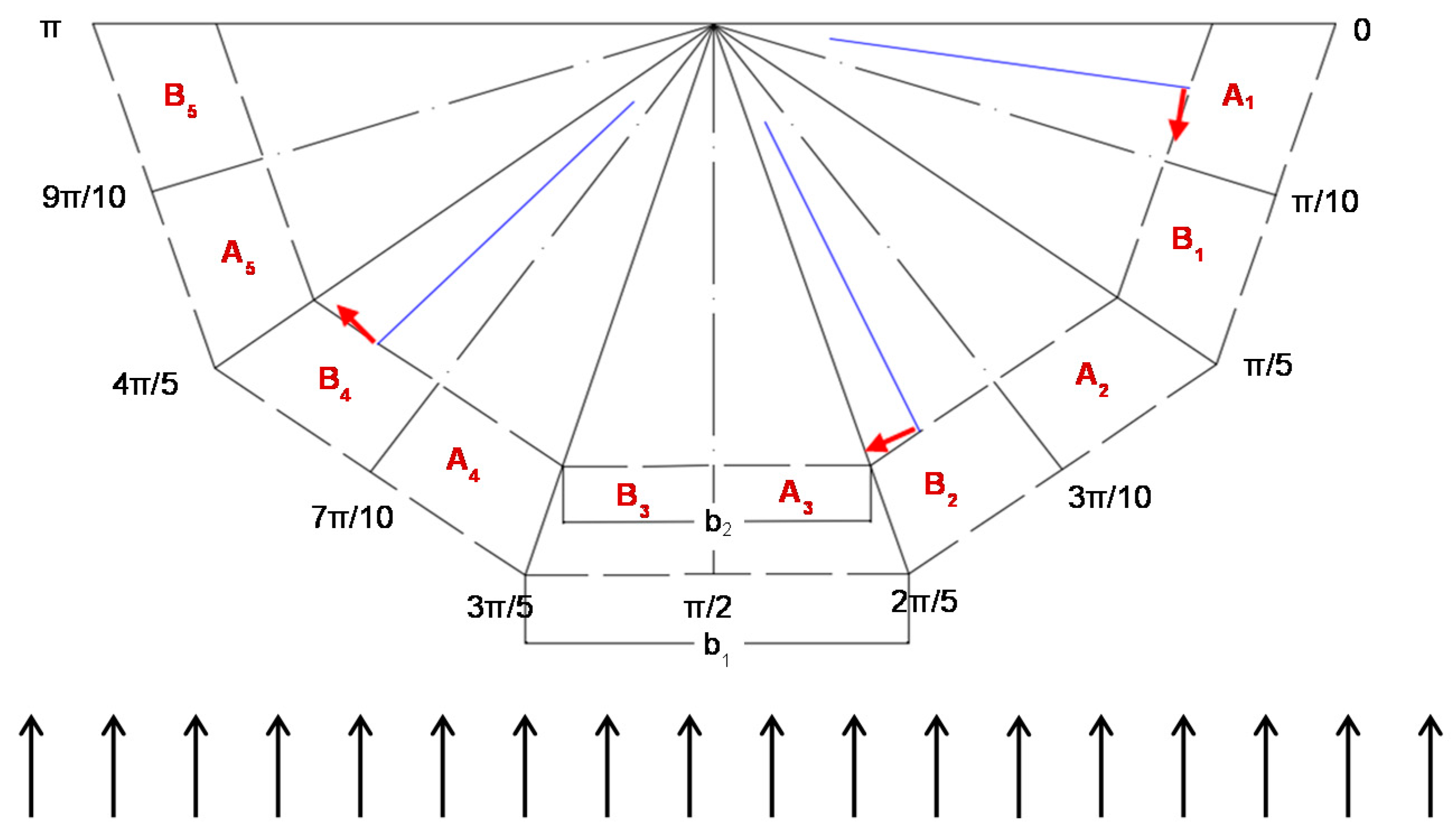
2.1. Mathematical Study
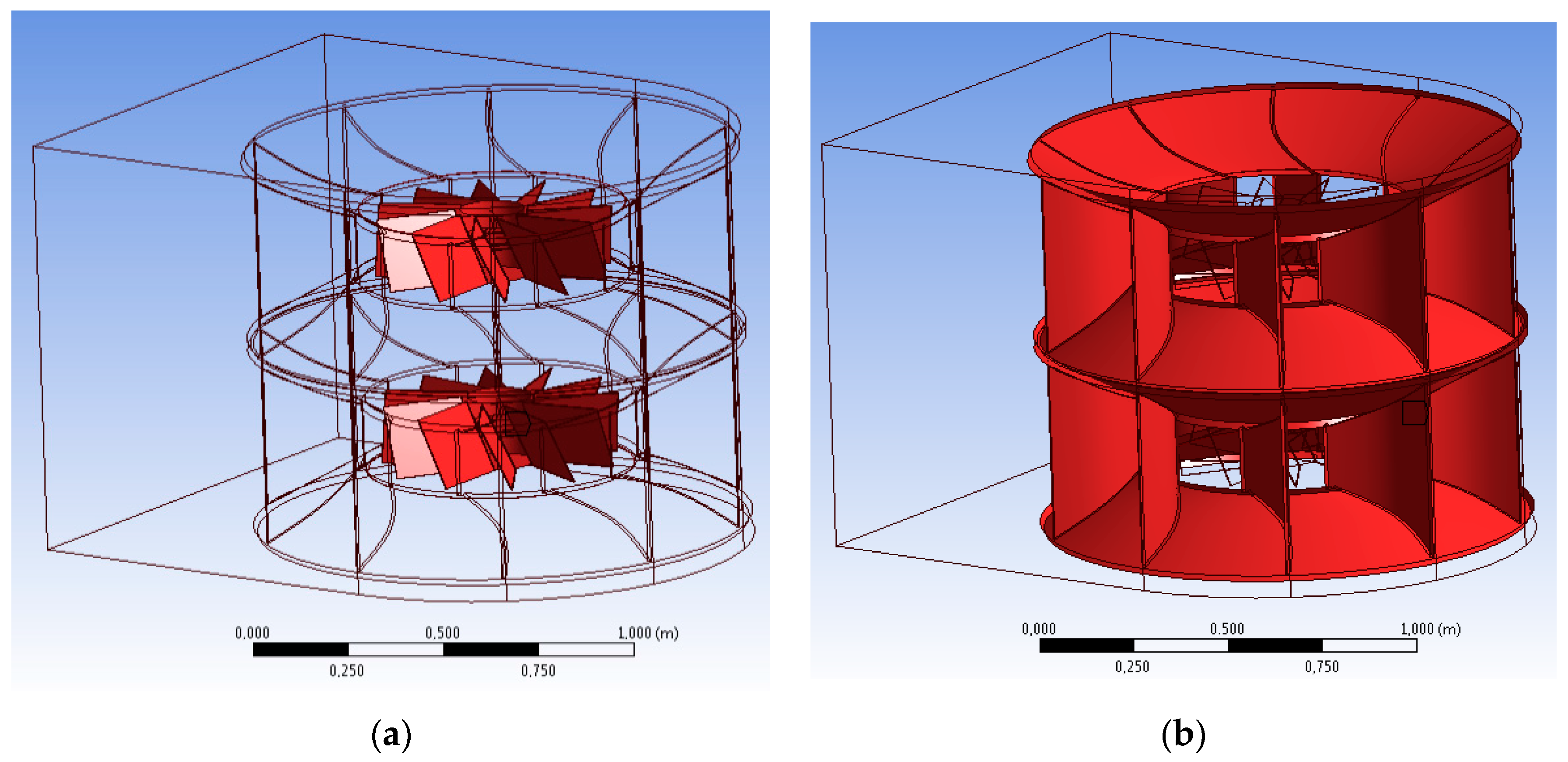
2.2. Computational Fluid Dynamics Study
3. Results and Discussion
3.1. Mathematical Results
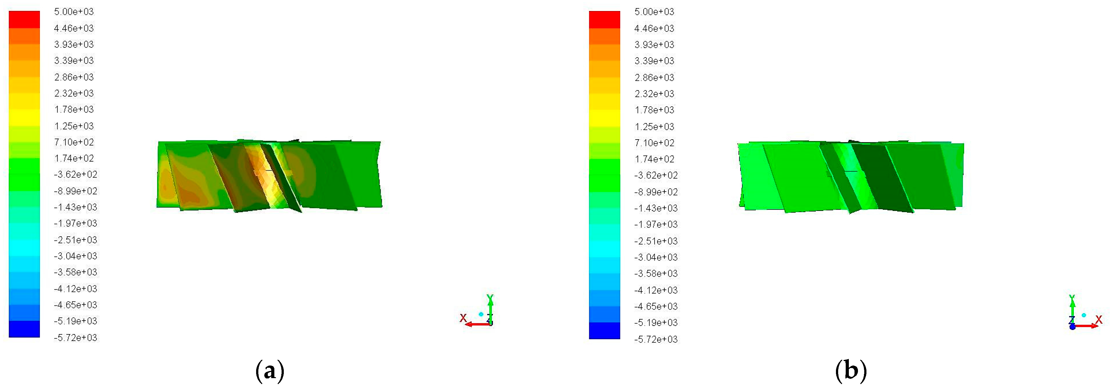
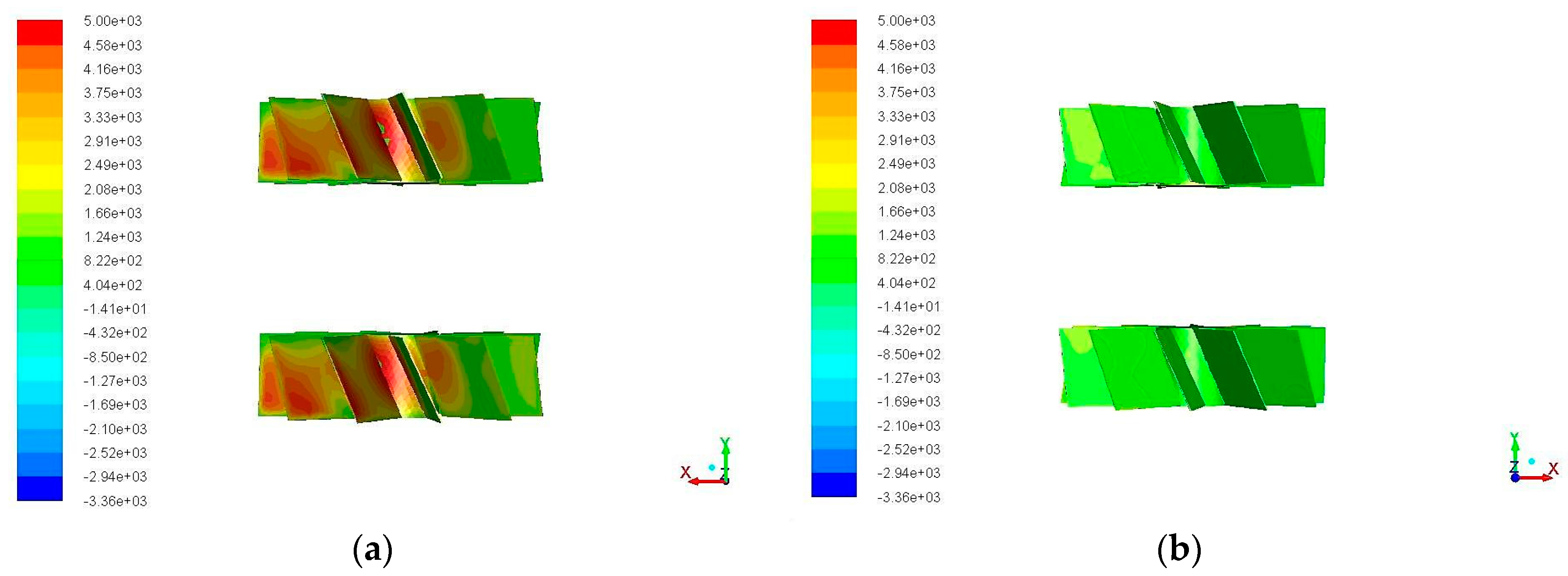
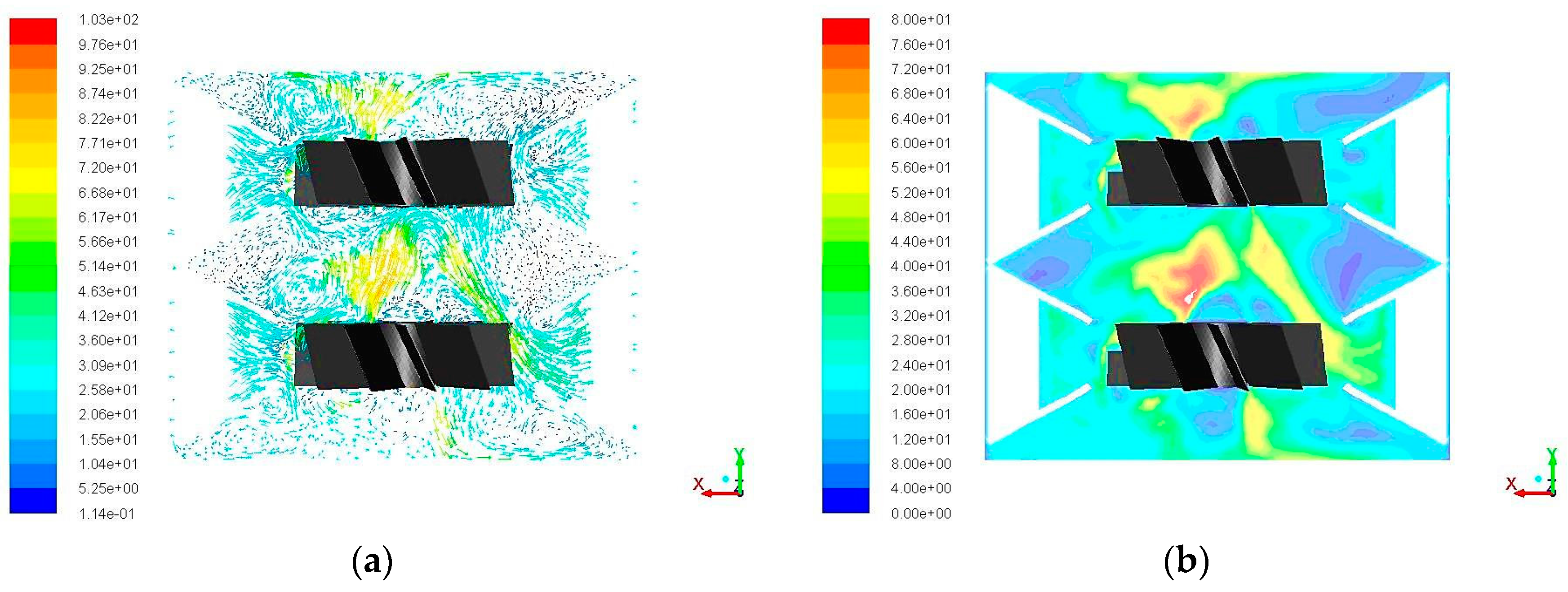
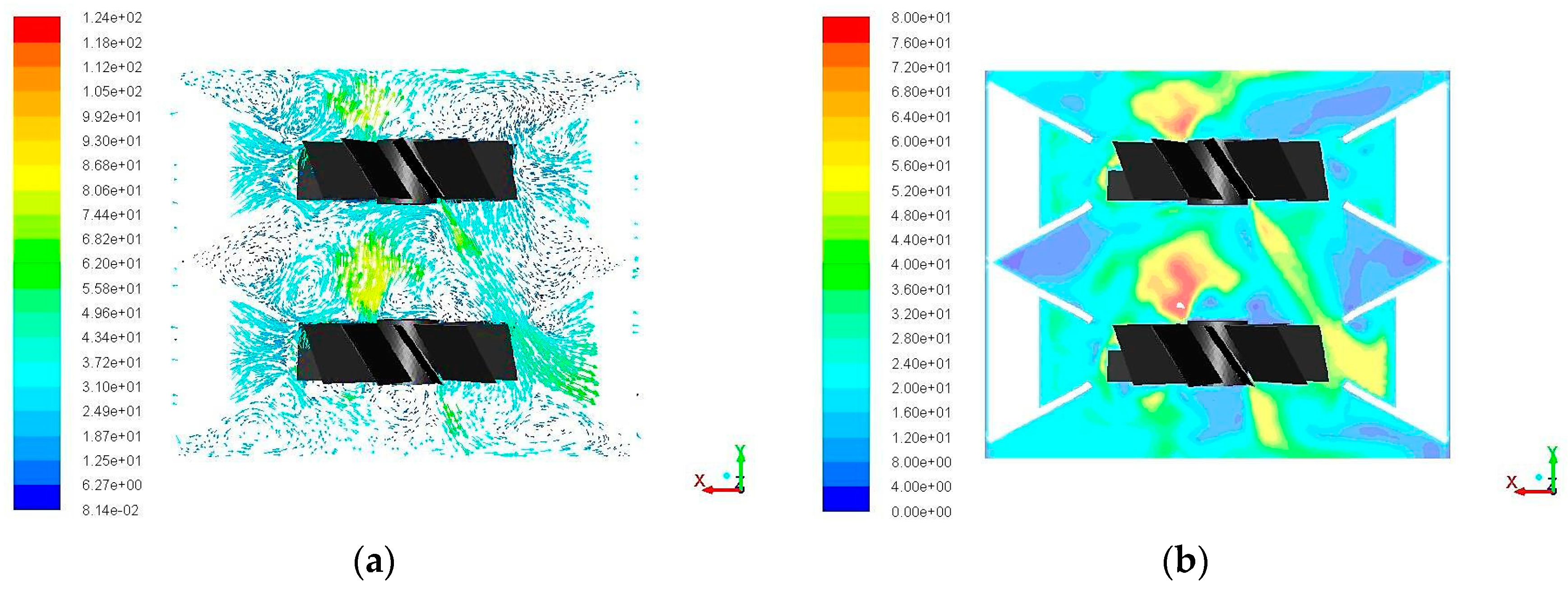
3.2. Computational Fluid Dynamics Results
4. Conclusions
Acknowledgments
Author Contributions
Conflicts of Interest
References
- Aslam Bhutta, M.M.; Hayat, N.; Farooq, A.U.; Ali, Z.; Jamil, S.R.; Hussain, Z. Vertical axis wind turbine—A review of various configurations and design techniques. J. Renew. Substain. Energy Rev. 2012, 16, 1926–1939. [Google Scholar] [CrossRef]
- Tang, Z.; Yao, Y.; Zhou, L.; Yu, B. A review on the new structure of savonius wind turbines. J. Adv. Mater. Res. 2013, 608–609, 467–478. [Google Scholar] [CrossRef]
- Ejiri, E.; Yabe, S.; Hase, S.; Ogiwara, M. Unsteady flow analysis of the vertical axis cross-flow wind turbine. In Proceedings of the ASME Fluids Engineering Division Summer Conference, Miami, FL, USA, 17–20 July 2006.
- Takao, M.; Maeda, T.; Kamada, Y.; Oki, M.; Kuma, H. A straight-bladed vertical axis wind turbine with a directed guide vane row. In Proceedings of the 5th Joint ASME/JSME Fluids Engineering Summer Conference, San Diego, CA, USA, 30 July–8 August 2007.
- Takao, M.; Takita, H.; Saito, Y.; Maeda, T.; Kamada, Y.; Toshimitsu, K. Experimental study of a straight-bladed vertical axis wind turbine with a directed guide vane row. In Proceedings of the 28th International Conference on Offshore Mechanics and Arctic Engineering—OMAE, Honolulu, HI, USA, 31 May–5 June 2009.
- Shahizare, B.; Nik Ghazali, N.N.B.; Chong, W.T.; Tabatabaeikia, S.S.; Izadyar, N. Investigation of the optimal omni-direction-guide-vane design for vertical axis wind turbines based on unsteady flow CFD simulation. J. Energies 2016, 9, 1–25. [Google Scholar] [CrossRef]
- Kim, D.; Gharib, M. Efficiency improvement of straight-bladed vertical-axis wind turbines with an upstream deflector. J. Wind Eng. Ind. Aerodyn. 2013, 115, 48–52. [Google Scholar] [CrossRef]
- Korprasertsak, N.; Leephakpreeda, T. Analysis and Optimal Design of Wind Boosters for Vertical Axis Wind Turbines at Low Wind Speed. J. Wind Eng. Ind. Aerodyn. 2016, 159, 9–18. [Google Scholar] [CrossRef]
- Wong, K.H.; Chong, W.T.; Yap, H.T.; Fazlizan, A.; Omar, W.Z.W.; Poh, S.C.; Hsiao, F.B. The design and flow simulation of a power-augmented shroud for urban wind turbine system. J. Energy Procedia 2014, 61, 1275–1278. [Google Scholar] [CrossRef]
- Nobile, R.; Vahdati, M.; Barlow, J.F.; Mewburn-Crook, A. Unsteady flow simulation of a vertical axis augmented wind turbine: A two-dimensional study. J. Wind Eng. Ind. Aerodyn. 2014, 125, 168–179. [Google Scholar] [CrossRef]
- Chen, T.Y.; Liao, Y.T.; Chen, Y.Y.; Liou, J.L. Application of a vortical stator assembly to augment the rotor performance of drag-type vertical-axis wind turbines. J. Aeronaut. Astronaut. Aviat. Ser. A 2015, 47, 75–84. [Google Scholar]
- Chen, T.Y.; Chen, Y.Y. Developing a Vortical Stator Assembly to Improve the Performance of Drag-Type Vertical-Axis Wind Turbines. J. Mech. 2015, 31, 693–699. [Google Scholar] [CrossRef]
- Pope, K.; Rodrigues, V.; Doyle, R.; Tsopelas, A.; Gravelsins, R.; Naterer, G.F.; Tsang, E. Effects of stator vanes on power coefficients of a zephyr vertical axis wind turbine. J. Renew. Energy 2010, 35, 1043–1051. [Google Scholar] [CrossRef]
- Burlando, M.; Ricci, A.; Freda, A.; Repetto, M.P. Numerical and experimental methods to investigate the behaviour of vertical-axis wind turbines with stators. J. Wind Eng. Ind. Aerodyn. 2015, 144, 125–133. [Google Scholar] [CrossRef]
- Chong, W.T.; Muzammil, W.K.; Fazlizan, A.; Hassan, M.R.; Taheri, H.; Gwani, M.; Kothari, H.; Poh, S.C. Urban Eco-Greenergy™ hybrid wind-solar photovoltaic energy system and its applications. J. Precis. Eng. 2015, 16, 1263–1268. [Google Scholar] [CrossRef]
- Tong, C.W.; Zainon, M.Z.; Chew, P.S.; Kui, S.C.; Keong, W.S.; Chen, P.K. Innovative power-augmentation-guide-vane design of wind-solar hybrid renewable energy harvester for urban high rise application. In Proceedings of the 10th Asian International Conference on Fluid Machinery, Kuala Lumpur, Malaysia, 21–23 October 2010; pp. 507–521.
- ANSYS® Academic Research, Release 16.0. Available online: http://www.ansys.com/ (accessed on 10 January 2017).
- Luo, J.Y.; Issa, R.I.; Gosman, A.D. Prediction of Impeller-Induced Flows in Mixing Vessels Using Multiple Frames of Reference. In IChemE Symposium Series; The Institution of Chemical Engineers: Rugby, UK, 1994; pp. 549–556. [Google Scholar]
- Menter, F.R. Two-Equation Eddy-Viscosity Turbulence Models for Engineering Applications. AIAA J. 1994, 32, 1598–1605. [Google Scholar] [CrossRef]


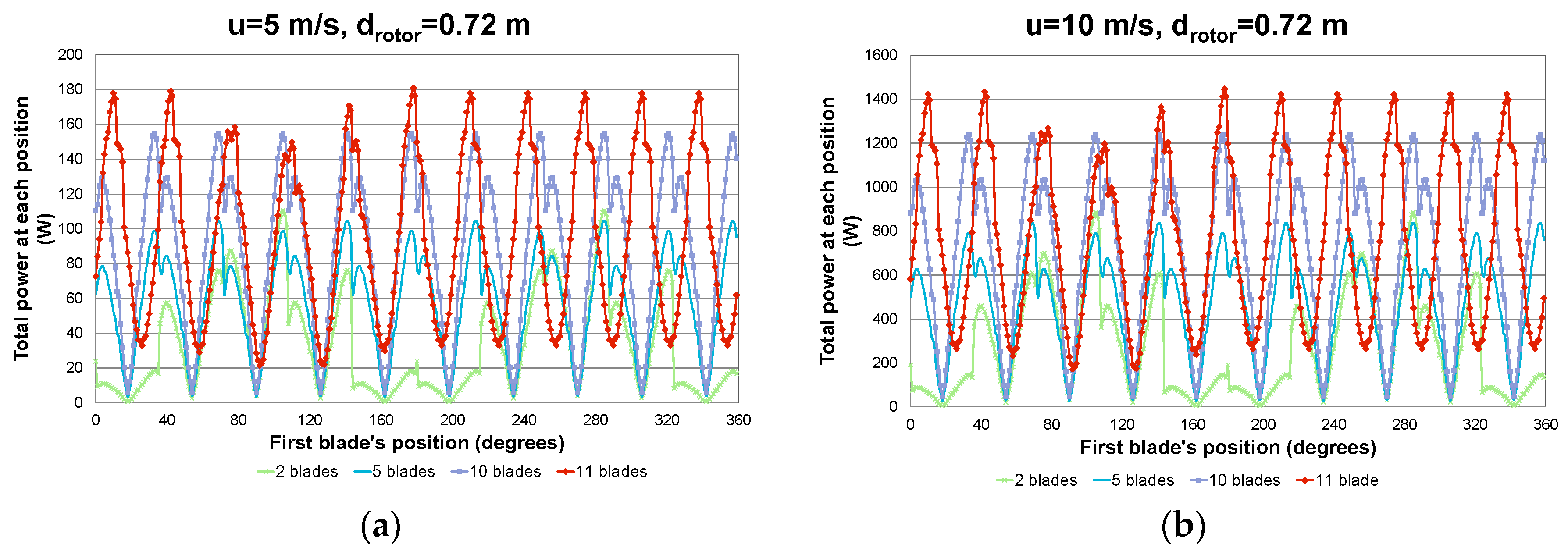
| Wind Speed u = 5 m/s | Wind Speed u = 10 m/s | |
|---|---|---|
| 2 blades | 32.9 | 263.6 |
| 3 blades | 42.1 | 336.7 |
| 4 blades | 50.3 | 402.1 |
| 5 blades | 57.8 | 462.2 |
| 6 blades | 64.8 | 440.3 |
| 7 blades | 71.4 | 571.5 |
| 8 blades | 77.8 | 622.1 |
| 9 blades | 83.8 | 670.7 |
| 10 blades | 89.7 | 717.6 |
| 11 blades | 95.4 | 762.8 |
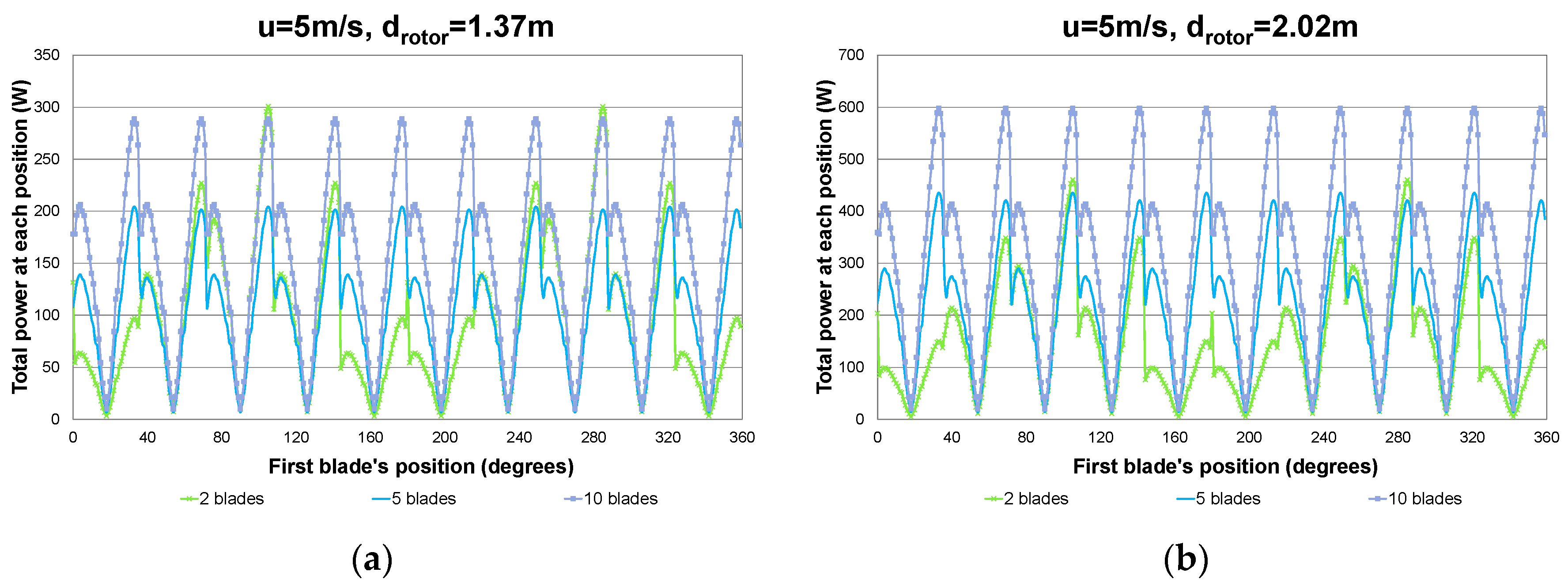
| drotor = 0.72 m | drotor = 1.37 m | drotor = 2.02 m | |
|---|---|---|---|
| 2 blades | 32.9 | 55.5 | 81.1 |
| 5 blades | 57.8 | 93.5 | 132.4 |
| 10 blades | 89.7 | 141.9 | 198.3 |
© 2017 by the authors. Licensee MDPI, Basel, Switzerland. This article is an open access article distributed under the terms and conditions of the Creative Commons Attribution (CC BY) license ( http://creativecommons.org/licenses/by/4.0/).
Share and Cite
Douvi, E.; Douvi, D.; Margaris, D.; Drosis, I. Numerical and Computational Analysis of a New Vertical Axis Wind Turbine, Named KIONAS. Computation 2017, 5, 8. https://doi.org/10.3390/computation5010008
Douvi E, Douvi D, Margaris D, Drosis I. Numerical and Computational Analysis of a New Vertical Axis Wind Turbine, Named KIONAS. Computation. 2017; 5(1):8. https://doi.org/10.3390/computation5010008
Chicago/Turabian StyleDouvi, Eleni, Dimitra Douvi, Dionissios Margaris, and Ioannis Drosis. 2017. "Numerical and Computational Analysis of a New Vertical Axis Wind Turbine, Named KIONAS" Computation 5, no. 1: 8. https://doi.org/10.3390/computation5010008