Effect of Carbon Concentration on the Sputtering of Carbon-Rich SiC Bombarded by Helium Ions


1
Beijing Key Laboratory of Passive Safety Technology for Nuclear Energy, School of Nuclear Science and Engineering, North China Electric Power University, Beijing 102206, China
2
The Second High School Attached to Beijing Normal University, Beijing 100088, China
3
Northwest Institute of Nuclear Technology, Xi’an 710024, China
*
Authors to whom correspondence should be addressed.
Computation 2018, 6(1), 19; https://doi.org/10.3390/computation6010019
Submission received: 10 January 2018
/
Revised: 3 February 2018
/
Accepted: 12 February 2018
/
Published: 14 February 2018
(This article belongs to the Section Computational Chemistry)
Abstract
:Silicon carbide (SiC) is considered as an important material for nuclear engineering due to its excellent properties. Changing the carbon content in SiC can regulate and control its elastic and thermodynamic properties, but a simulation study of the effect of carbon content on the sputtering (caused by the helium ions) of SiC is still lacking. In this work, we used the Monte-Carlo and molecular dynamics simulation methods to study the effects of carbon concentration, incidence energy, incident angle, and target temperature on the sputtering yield of SiC. The results show that the incident ions’ energy and angle have a significant effect on sputtering yield of SiC when the carbon concentration in SiC is around 62 at %, while the target temperature has a little effect on the sputtering yield of SiC. Our work might provide theoretical support for the experimental research and engineering application of carbon fiber-reinforced SiC that be used as the plasma-facing material in tokamak fusion reactors.
1. Introduction
Nuclear energy is an important type of clean energy and cannot be completely replaced currently. Silicon carbide (SiC) is an important material in TRISO-coated fuel particles—the type of nuclear fuel found in high-temperature gas-cooled reactors such as the Pebble Bed Reactor. A layer of SiC gives coated fuel particles structural support, and is the main diffusion barrier to the release of fission products [1]. Silicon carbide composite material has been investigated for use as a replacement for Zircaloy cladding in light water reactors. The composite consists of SiC fibers wrapped around a SiC inner layer and surrounded by a SiC outer layer [2]. Nuclear fusion is considered as a promising sustainable energy source and a feasible solution to solve the energy crisis the world will face in the future [3,4,5]. In order to commercialize nuclear fusion energy, the research on materials is indispensable because the materials used in the fusion reactor are critical to its success. Plasma-facing material is an important one among different materials which be used in a fusion reactor. It is used in an extremely harsh environment, such as extremely high heat flux and ion beam irradiation. The plasma-facing material plays a vital role in the safety of the nuclear fusion reactor’s [5,6,7,8] operation.
The first wall material has to withstand very high fusion neutron flux and heat flux, and its service time determines the economy of a nuclear fusion reactor. The service life of SiC is short because the ions’ erosion is regarded as unacceptable in the nuclear fusion reactor. This is why SiC has been removed from the first wall material in the International Thermonuclear Experimental Reactor (ITER) despite its many advantages, such as high strength, high hardness, good temperature resistance, low neutron activation properties, low decay heat, and low tritium permeation and retention [9,10,11,12,13,14,15,16,17,18,19,20]. SiC is still worth studying for the following two reasons: firstly, it is considered as an alternative material for the potential failure of tungsten; secondly, tritium has a high mobility and retention in tungsten, which will reduce the operational economy of the nuclear fusion reactor. SiC is beneficial to reducing the tritium penetration and increasing the efficiency of the reactor [21,22]. Some scientists have suggested that a thin layer of SiC can be used to cover the tungsten plasma-facing components, which can prevent tritium penetration [23,24,25]. In recent years, there are many fusion devices which use SiC as the plasma-facing material (such as KSTAR, JT-60SA, ARIES-AT, DREAM and etc.) in order to reduce the probability of catastrophic fracture [26,27,28,29,30].
However, pure SiC has an inherent brittle nature, which limits its application in the nuclear reactor structural material [31]. In order to enhance the toughness of SiC, carbon fiber reinforcement is a good method which is widely proposed. Carbon fiber has some advantages, such as high strength and high modulus at high temperature. Carbon fiber-reinforced SiC material has many excellent properties, such as low density, low linear expansion coefficient, oxidation resistance, creep resistance, chemical resistance, high resistance to thermal shock, salt fog, and electromagnetic wave absorption characteristics, in addition to the intrinsic properties of SiC [32,33,34,35,36,37]. Furthermore, carbon fiber-reinforced SiC composites do not perform brittleness in the fracture process, carbon fiber-reinforced SiC has a high thermal conductivity property, and it will be improved with the development of science and technology [38,39]. Therefore, it can be widely used in aerospace, deep sea, electronics, weapons, and nuclear fields as structural material.
In a nuclear application, carbon fiber-reinforced SiC material is inevitably subjected to different kinds of ions’ irradiation [40,41]. It is important to study the effect of the fusion plasma on the performance of carbon fiber-reinforced SiC. Carbon fiber-reinforced SiC with high performance can work on the safe operation of fusion reactor at a high power and high-temperature level, which wins the favor of the researchers all over the world. There are some good research works reporting on the irradiation effect of SiC. In 1976, J. Bohdansky measured the sputtering yield of SiC that is bombarded by deuterium, tritium, and helium ions with an incident energy from 600 eV to 7.5 keV [40]. In 2001, E. Salonen studied the bombardment of 30 eV hydrogen ion on amorphous hydrogenated SiC surfaces [10] through molecular dynamics (MD) simulation. In 2009, the experimental study of Manuel Gamero-Castaño showed the sputtering yield of SiC under nanodroplet bombardment at normal incidence [42]. In 2010, Carlos Ziebert studied the sputtering yield of SiC bombarded by argon atoms with the energy from 20 eV to 1000 eV [43] using MD simulation combined with experimental method. In 2013, Rafael Borrajo-Pelaez found the sputtering yield of SiC as functions of the nanodroplet velocity [44]. However, the study of the sputtering yield (caused by different ions’ irradiation) of carbon fiber-reinforced SiC is not sufficient. Most of the current studies focus on the change of mechanical properties and thermal conductivity of carbon fiber-reinforced SiC irradiated by ions [45,46]. In 1981, K. Sone conducted an experimental study of the sputtering yield of SiC with different atomic fractions of silicon and carbon bombarded by a 3.0 keV tritium ion beam [47] study. In 2002, E. Salonen studied the chemical sputtering of carbon by silicon doping under 20 eV deuterium irradiation using MD simulation [48]. Our previous research work [49] showed that the carbon content in carbon-rich SiC has a significant effect on the elastic and thermodynamic properties of SiC. In this paper, we study the effects of carbon concentration, incidence angle, incidence energy, and target temperature on the sputtering yield of SiC through Monte-Carlo (MC) and molecular dynamics (MD) simulation methods. We hope that our work might shed some light on the development of carbon fiber-reinforced SiC.
2. Models and Computational Details
MD simulation has been widely applied to simulate the sputtering of material under irradiation, and we used the large-scale atomic molecular massively parallel simulator (LAMMPS) code [50] to investigate the sputtering of the different carbon content carbon-rich SiC under helium ions bombardment. The hybrid Tersoff/ZBL (Ziegler–Biersack–Littmark) potential was used to describe the interaction between Si atom and C atom in SiC. The Tersoff/ZBL potential is revised through Tersoff potential. The Tersoff/ZBL potential is a function formed by the Tersoff function and Ziegler–Biersack–Littmark universal screening function [51,52]; it can describe the collision process of incident particles and target atoms very well. The Lennard–Jones potential was used to describe the Si-He, C-He, and He-He interactions [53].
The initial SiC target was diamond cubic crystal structure SiC, and the size of the simulation cell was 40 × 40 × 30 lattice units with the lattice parameter of 4.36 Å [20]. The periodic boundary conditions were applied in the X-direction and Y-direction, and the free boundary conditions were applied in the Z-direction. The injection point of helium ions was 30 Å from the SiC surface in the Z-direction. The different carbon content carbon-rich SiC was formed by substituting partial Si atoms with C atoms. A microcanonical ensemble was used in all simulation works, and the last three layers were fixed in space to withstand the momentum of energetic ions. The MD simulations had two main stages. In the first stage, the mobile Si and C atoms in SiC were assigned an initial velocity with a Gaussian distribution at the desired temperature, allowing the simulation of heat conduction in the fusion reactor. The equilibrium process took 5 ps with a time step of 0.001 ps. In the second stage, 3000 helium ions continually bombarded the SiC target with a time interval of 0.003 ps at different incidence angles: , , , , , and . During the bombardment process, the time step was 0.005 ps and the total simulation time was 170 ps. The energy of incident helium ions varied from 0 eV to 100 eV, and the interval was 10 eV.
SRIM is a MC code that is widely used to simulate the ions’ irradiation of some materials [54]. The collision between the incident ions and the target atoms in a material is described by a two-body collision. The incident ions are transported in the target material, and this process is considered with a series of independent collisions in the target atoms, where each independent collision scattering uses a numerical integration solution. The interaction between the incident ions and the target atoms is the ZBL potential, and all parameters were chosen to ensure that the conditions were the same as the LAMMPS simulation.
3. Results and Discussion
In this section, we present the results of our simulation and the discussion of these results. This section is divided into three parts. Section 3.1, Section 3.2, Section 3.3 and Section 3.4 show the effect of the carbon concentration, incident energy, incident angle, and substrate temperature on sputtering yield, respectively.
3.1. Carbon Concentration Effect
In order to investigate the effect of the carbon content on the sputtering of carbon-rich SiC, the carbon concentration in our simulated carbon-rich SiC varied from 50 at % to 100 at %, and we used the LAMMPS and SRIM to calculate the sputtering yield of carbon-rich SiC.
Figure 1 shows the top view of the atomic structure of perfect SiC bulk and SiC bulk with 62 at % C concentration before and after the helium bombardment. The red balls represent C atoms and the blue balls represent Si atoms, respectively. Figure 1a shows the perfect SiC bulk. There are no incident ions at this stage, and it is the original state of helium ions irradiation. Figure 1b is SiC bulk with 62 at % carbon concentration. There is also no incident helium ions at the original state. We can see that the arrangement of atoms in Figure 1b is not as regular as that of Figure 1a. Subsequently, at the beginning of the bombardment of the helium ions, the SiC bulk with 62 at % C concentration becomes disordered to some extent only on its surface, as shown in Figure 1c. After continuous irradiation, we can see that many atoms in the SiC target are sputtered and the SiC bulk becomes more disordered, as shown in Figure 1d. From Figure 1c,d, we can observe the interesting phenomenon that the carbon atoms cluster on the SiC surface.
Figure 2 shows the sputtering yield of SiC target as a function of the carbon concentration. As we can see from the Figure 2, before the C concentration reached 80 at %, the effect of the C concentration on the sputtering yield of SiC was not very obvious. When the C concentration was greater than 80 at %, the sputtering yield of Si rapidly increased with the increase of C concentration. Overall, there was an upward trend in the sputtering yield of SiC with increasing C concentration, regardless of the incident ions’ energies (50 eV or 100 eV). The sputtering yield caused by the 50 eV incident helium ions was slightly lower than the result caused by the 100 eV incident ions. The reason (why the change of the sputtering yield of SiC is not obvious) is that the Si atoms in SiC target were partially replaced by C atoms and the substitutions were random; some C-Si covalent bonds turned into the C-C bonds. The strength of the C-C bond is slightly larger than the Si-C bond. However, the displacement threshold energy of C atoms is smaller than that of Si atoms [52]. Before the C concentration in SiC reached 80 at %, the sputtering yield of SiC was affected by the covalent bonds’ change. We can find when the C concentration was 62 at %, the sputtering yield of SiC was the lowest in all SiC with different C concentrations—even lower than the value when the C concentration was 50 at %. The sputtering yield of SiC did not steadily increase with increasing C concentration, but the value went up and down. When the C concentration in SiC was greater than 80 at %, the majority of atoms were carbon atoms. In this case, the displacement threshold energy dominated the sputtering yield of SiC. When the incident ions bombarded the SiC target, the carbon atoms were easy to knock out from their lattice positions and to be the sputtered atoms. So, the sputtering yield of the SiC target increased rapidly with increasing C concentration. Both the simulations of LAMMPS and SRIM had the same trend. Comparing these two simulated results, there were some discrepancies. The result of SRIM was significantly higher than the result obtained by LAMMPS. SRIM simulation does not involve structural changing. Additionally, SRIM ignores the influence of surrounding target atoms and uses binary collision to deal with the interaction between ions and target atoms. This is why the sputtering yield by SRIM simulation is greater than that of the LAMMPS simulation.
3.2. Energy Effect
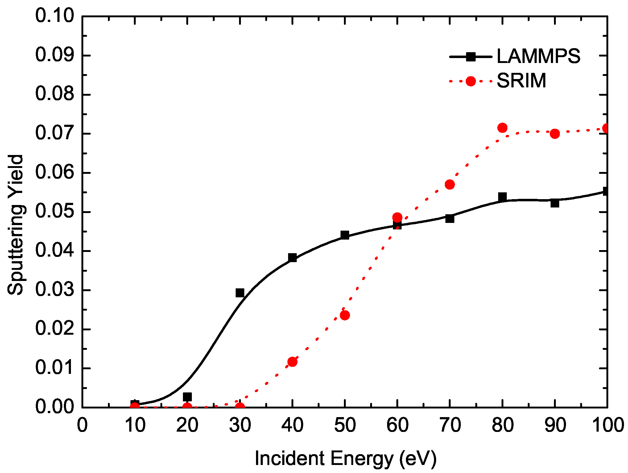
Figure 2 shows the sputtering yield of SiC bulk with 62 at % C concentration as a function of incident ions’ energy. In the LAMMPS simulation, there was no sputtering yield before the incident ions’ energy was greater than 10 eV. When the incident energy of ions varied from 10 eV to 60 eV, the sputtering yield of SiC increased rapidly with the increase of the incident ion energy. When the incident ions’ energy was bigger than 60 eV, the sputtering yield of SiC tended to increase slowly with increasing incident ions’ energy. In the SRIM simulation, there was no sputtering yield before the incident ions energy was greater than 20 eV. When the incident ions’ energy varied from 20 eV to 80 eV, the sputtering yield of SiC increased rapidly with the increase of the incident ion energy. When the incident ions’ energy was bigger 80 eV, the sputtering yield of SiC tended to increase slowly. Generally speaking, the result of the SRIM simulation agreed with the result of the LAMMPS simulation. As we can see from the figure, the sputtering yield of SiC depended on the incident energy of helium atoms. The sputtering threshold energy was 20 eV in the SRIM simulation, while it was 10 eV in the LAMMPS simulation. The Si atoms in SiC were randomly replaced by C atoms in the LAMMPS simulation, but in the SRIM simulation we cannot consider the structure of SiC. The difference in sputtering threshold energy caused by the presence of a small amount of C atoms on the SiC target surface and the surface bonding energy of SiC was less than that of C atoms, which led to the different sputtering threshold energies between the two simulations. When incident ions’ energy was greater than the sputtering threshold energy, the depth of the incident ions entering the SiC target increased with increasing energy. With the incident ions’ energy increasing, the energy of the primary kicked atoms also increased, which made the cascaded collision region larger. From the point of view of the sputtering threshold energy, the sputtering yield of SiC increased with increasing incident ion energy. When the incident ions’ energy was less than 60 eV, the simulation result of SRIM was less than that of LAMMPS, because the sputtering threshold energy had a great effect on the sputtering yield of SiC at this stage. When the incident ion energy was greater than 60 eV, the effect of sputtering threshold energy became very weak, so the SRIM result was greater than that of LAMMPS, for the same reason as mentioned above. When the incident ions’ energy was greater than 80 eV, due to the limitation of non-periodicity in the Z direction, the cascaded collision region exceeded the length of the Z direction. This did not cause a further increase in cascade collisions; the sputtering yield of SiC tended to be close to a constant. It is clear that the sputtering yield of SiC increased with increasing incident ion energy, as shown in Figure 3. From this section, we can conclude that the incident ion energy had a significant effect on sputtering yield of SiC, especially in the very low energy region.
3.3. Incident Angle Effect
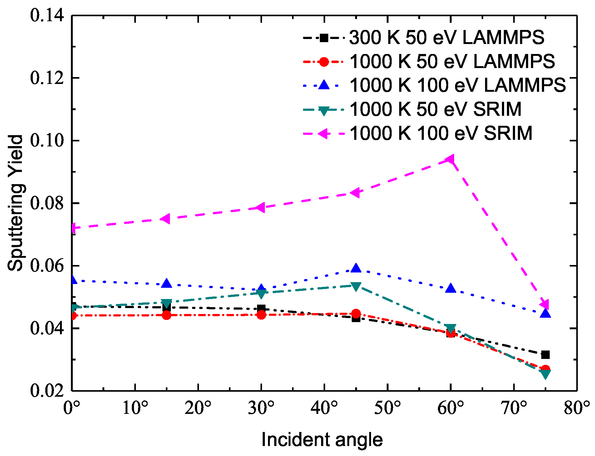
Figure 4 shows the sputtering yield of SiC with 62 at % C concentration as a function of the incident angle. We define the incident ions’ angle as the angle between the incident particle and the Z direction. The incidence angles of our simulation were , , , , , and . The temperature of the SiC target was 1000 K and 300 K. From Figure 4, we can see that the sputtering yield of SiC was divided into three parts, and the SRIM simulation results were greater than those of LAMMPS. The reason why the SRIM simulation results were greater than those of LAMMPS has been explained in the previous section. When the incident ions’ angle was between and , the sputtering yield did not change significantly; when the incident ions’ angle was between and , the sputtering yield of SiC reached its peak value at . When the incident ions’ angle was greater than , the sputtering yield of SiC dropped rapidly. When the incident ions’ angle varied from to , the incident ions bombarded the SiC target surface atoms at the first layer, which led to a relatively high energy recoil of atoms, causing the elastic deformation of the surface. Some of these recoiled atoms could further collide with other stationary atoms, resulting in a series of cascading collisions in the deeper regions. The energy of the recoiled atoms was released gradually. When recoiled atoms reach the surface, some of them still have the energy to escape from the target surface and become sputtered atoms. When the incident ions’ angle varied from to , the incident ions passed through the target surface at the first layer, the surface atoms leaving the surface of the substrate to become sputtered atoms. The sputtering of the atoms destroys the surface lattice of the substrate. The subsequent series of collisions, incident ions, and target atoms are easily removed from where the lattices are destroyed. When the incident ions’ angle was greater than , the velocity of the incident atoms in the Z direction was relatively small, and the incident ions did not penetrate the surface into the interior of the substrate, only colliding on the surface of the substrate. The region of cascade collision was small, and the sputtered atoms were reduced, so we can see the sputtering yield of SiC was relatively small.
3.4. Temperature Effect
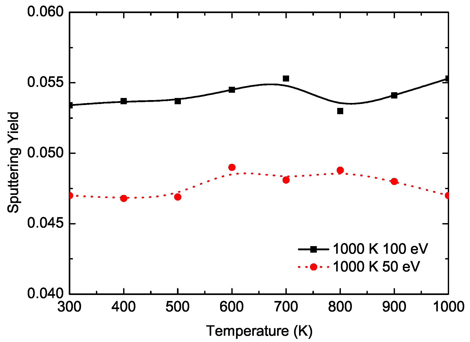
Figure 5 shows the sputtering yield of SiC bulk with 62 at % C concentration as a function of substrate temperature. The target was bombarded by helium ions with energy of 50 eV and 100 eV. When the temperature of the SiC target varied from 300 K to 500 K, the curve of sputtering and temperature was approximately a straight line. After the target temperature exceeded 500 K, the sputtering rate fluctuated slightly. In general, we can see that the effect of substrate temperature on the sputtering yield was not obvious. We also can see the same situation from Figure 4. As the SiC target temperature increased, the lattice vibration in the SiC bulk became obvious, but the kinetic energy of the target atoms obtained from the incident ions was still insufficient to overcome the bondage of the covalent bond. So, when the SiC target temperature varied from 300 K to 500 K, the sputtering yields of SiC did not increase, still remaining constant. As the SiC target temperature rose to exceed 500 K, the target atoms acquired more kinetic energy. When the incident ions bombarded the SiC target, some of the doped C atoms were easily separated from their initial positions. Those atoms who broke the restraint of bondage still had a certain kinetic energy and could continue to move within the SiC target. The collision of these atoms with other atoms can cause cascading collisions within a small region. Only the atoms moving from the Z direction were regarded as the sputtered atoms. X direction and Y direction movement of the atoms will only cause a certain degree of confusion within the SiC target, which does not involve sputtering. When the target temperature was greater than 500 K, the sputtering yield of SiC was fluctuating. Overall, we can conclude that the target temperature had little effect on the sputtering yield of SiC.
4. Conclusions
MD and MC simulations were used to investigate the sputtering yield of SiC bombarded by helium ions. Based on the results, we obtained some interesting conclusions: (1) The sputtering yield of SiC was almost steady when the C concentration varied from 50 at % to 68 at %; the lowest sputtering yield of SiC happened when the C concentration was 62 at %; (2) the incident ions’ energy had a significant effect on sputtering yield of SiC, especially in the very low energy region; (3) the effect of the incident ions’ angle on the sputtering yield of SiC was obvious. When the incident ions’ angle was between and , due to the destruction of the surface lattice, the sputtering yield of SiC significantly increased and reached its peak; (4) the target temperature has little effect on the sputtering yield of SiC. Through these calculations, considering the low sputtering yield, we can find a better carbon-rich SiC with excellent properties for application in nuclear engineering.
Acknowledgments
This work is supported by the Fundamental Research Funds for the Central Universities under grant No. 2017MS079.
Author Contributions
Xinhao Liang and Yang Li conceived the simulation. Yang Li and Zheng Zhang performed the simulations. Xinhao Liang and Yang Li wrote the paper. Qiang Zhao and Xiaoping Ouyang supervise the whole work.
Conflicts of Interest
The authors declare no conflict of interest.
References
- López-Honorato, E.; Tan, J.; Meadows, P.J.; Marsh, G.; Xiao, P. TRISO coated fuel particles with enhanced SiC properties. J. Nucl. Mater. 2009, 392, 219–224. [Google Scholar] [CrossRef]
- Carpenter, D.; Ahn, K.; Kao, S.P.; Hejzlar, P.; Kazimi, M.S. Assessment of Silicon Carbide Cladding for High Performance Light Water Reactors; Nuclear Fuel Cycle Program (CANES Reports); Massachusetts Institute of Technology: Cambridge, MA, USA, 2007. [Google Scholar]
- Iveković, A.; Novak, S.; Dražić, G.; Blagoeva, D.; de Vicente, S.G. Current status and prospects of SiCf/SiC for fusion structural applications. J. Eur. Ceram. Soc. 2013, 33, 1577–1589. [Google Scholar] [CrossRef]
- Moyer, M. Fusion’s false dawn. Sci. Am. 2010, 302, 50–57. [Google Scholar] [CrossRef] [PubMed]
- Jones, R.H.; Giancarli, L.; Hasegawa, A.; Katoh, Y.; Kohyama, A.; Riccardi, B.; Snead, L.L.; Weber, W.J. Promise and challenges of SiCf/SiC composites for fusion energy applications. J. Nucl. Mater. 2002, 307, 1057–1072. [Google Scholar] [CrossRef]
- Linke, J. High heat flux performance of plasma facing materials and components under service conditions in future fusion reactors. Fusion Sci. Technol. 2012, 61, 246–255. [Google Scholar] [CrossRef]
- Linke, J.; Escourbiac, F.; Mazul, I.V.; Nygren, R.; Rödig, M.; Schlosser, J.; Suzuki, S. High heat flux testing of plasma facing materials and components—Status and perspectives for ITER related activities. J. Nucl. Mater. 2007, 367, 1422–1431. [Google Scholar] [CrossRef]
- Kim, H.S.; Noh, S.J.; Kweon, J.J.; Lee, C.E. Influence of irradiation with low-energy helium ions on graphite and tungsten for fusion applications. J. Korean Phys. Soc. 2013, 63, 1422–1426. [Google Scholar] [CrossRef]
- Causey, R.A. Sputtering and codeposition of silicon carbide with deuterium. J. Nucl. Mater. 2003, 313, 450–454. [Google Scholar]
- Salonen, E.; Nordlund, K.; Keinonen, J.; Wu, C.H. Chemical sputtering of amorphous silicon carbide under hydrogen bombardment. Appl. Surf. Sci. 2001, 184, 387–390. [Google Scholar] [CrossRef]
- Li, M.; Yue, Y. Molecular dynamics study of thermal transport in amorphous silicon carbide thin film. RSC Adv. 2014, 4, 23010–23016. [Google Scholar] [CrossRef]
- Snead, L.L.; Nozawa, T.; Ferraris, M.; Katoh, Y.; Shinavski, R.; Sawan, M. Silicon carbide composites as fusion power reactor structural materials. J. Nucl. Mater. 2011, 417, 330–339. [Google Scholar] [CrossRef]
- Nozawa, T.; Hinoki, T.; Hasegawa, A.; Kohyama, A.; Katoh, Y.; Snead, L.L.; Henager, C.H., Jr.; Hegeman, J.B.J. Recent advances and issues in development of silicon carbide composites for fusion applications. J. Nucl. Mater. 2009, 386, 622–627. [Google Scholar]
- Hinoki, T.; Katoh, Y.; Snead, L.L.; Jung, H.C.; Ozawa, K.; Katsui, H.; Zhong, Z.H.; Kondo, S.; Park, Y.H.; Shih, C.; et al. Silicon carbide and silicon carbide composites for fusion reactor application. Mater. Trans. 2013, 54, 472–476. [Google Scholar] [CrossRef]
- Katoh, Y.; Ozawa, K.; Hinoki, T.; Choi, Y.; Snead, L.L.; Hasegawa, A. Mechanical properties of advanced SiC fiber composites irradiated at very high temperatures. J. Nucl. Mater. 2011, 417, 416–420. [Google Scholar] [CrossRef]
- Hegeman, J.B.J.; Van der Laan, J.G.; Van Kranenburg, M.; Jong, M.; d’Hulst, D.; Ten Pierick, P. Mechanical and thermal properties of SiCf/SiC composites irradiated with neutrons at high temperatures. Fusion Eng. Des. 2005, 75, 789–793. [Google Scholar] [CrossRef]
- Shikama, T.; Fujitsuka, M.; Araki, H.; Noda, T.; Tanabe, T.; Shinno, H. Irradiation behavior of carbon-boron compounds and silicon carbide composites developed as fusion reactor materials. J. Nucl. Mater. 1992, 191, 611–615. [Google Scholar] [CrossRef]
- Rieth, M.; Dudarev, S.L.; De Vicente, S.G.; Aktaa, J.; Ahlgren, T.; Antusch, S.; Armstrong, D.E.J.; Balden, M.; Baluc, N.; Barthe, M.F.; et al. Recent progress in research on tungsten materials for nuclear fusion applications in Europe. J. Nucl. Mater. 2013, 432, 482–500. [Google Scholar] [CrossRef]
- Philipps, V. Tungsten as material for plasma-facing components in fusion devices. J. Nucl. Mater. 2011, 415, S2–S9. [Google Scholar] [CrossRef]
- Katoh, Y.; Snead, L.L.; Szlufarska, I.; Weber, W.J. Radiation effects in SiC for nuclear structural applications. Curr. Opin. Solid State Mater. Sci. 2012, 16, 143–152. [Google Scholar] [CrossRef]
- Nakamura, H.; Shu, W.; Hayashi, T.; Nishi, M. Tritium permeation study through tungsten and nickel using pure tritium ion beam. J. Nucl. Mater. 2003, 313, 679–684. [Google Scholar] [CrossRef]
- Nakamura, H.; Hayashi, T.; Kakuta, T.; Suzuki, T.; Nishi, M. Tritium permeation behavior implanted into pure tungsten and its isotope effect. J. Nucl. Mater. 2001, 297, 285–291. [Google Scholar] [CrossRef]
- Causey, R.A.; Wampler, W.R. The use of silicon carbide as a tritium permeation barrier. J. Nucl. Mater. 1995, 220, 823–826. [Google Scholar] [CrossRef]
- Wright, G.M.; Durrett, M.G.; Hoover, K.W.; Kesler, L.A.; Whyte, D.G. Silicon Carbide as a tritium permeation barrier in tungsten plasma-facing components. J. Nucl. Mater. 2015, 458, 272–274. [Google Scholar] [CrossRef]
- Causey, R.A.; Garde, J.M.; Buchenauer, D.A.; Calderoni, P.; Holschuh Jr, T.; Youchison, D.L.; Wright, M.; Kolasinski, R.D. Silicon Carbide Tritium Permeation Barrier for Steel Structural Components; Sandia National Laboratories: Livermore, CA, USA, 2010. [Google Scholar]
- Pramono, Y.; Sasaki, K.; Yano, T. Release and diffusion rate of helium in neutron-irradiated SiC. J. Nucl. Sci. Technol. 2004, 41, 751–755. [Google Scholar] [CrossRef]
- Lewinsohn, C.A.; Youngblood, G.E.; Henager Jr, C.H.; Simonen, E.P.; Jones, R.H. Time-dependent failure mechanisms in silicon carbide composites for fusion energy applications. J. Nucl. Mater. 2000, 283, 584–587. [Google Scholar] [CrossRef]
- Raffray, A.R.; El-Guebaly, L.; Gordeev, S.; Malang, S.; Mogahed, E.; Najmabadi, F.; Sviatoslavsky, I.; Sze, D.K.; Tillack, M.S.; Wang, X.; et al. High performance blanket for ARIES-AT power plant. Fusion Eng. Des. 2001, 58, 549–553. [Google Scholar] [CrossRef]
- Raffray, A.R.; El-Guebaly, L.; Malang, S.; Sviatoslavsky, I.; Tillack, M.S.; Wang, X.; ARIES Team. Advanced power core system for the ARIES-AT power plant. Fusion Eng. Des. 2006, 80, 79–98. [Google Scholar] [CrossRef]
- Seki, Y.; Mori, S.; Nishio, S.; Ueda, S.; Kurihara, R. Neutron Streaming Evaluation for the DREAM Fusion Power Reactor. J. Nucl. Sci. Technol. 2000, 37, 268–275. [Google Scholar] [CrossRef]
- Kikuchi, H.; Kalia, R.K.; Nakano, A.; Vashishta, P.; Branicio, P.S.; Shimojo, F. Brittle dynamic fracture of crystalline cubic silicon carbide (3C-SiC) via molecular dynamics simulation. J. Appl. Phys. 2005, 98, 103524. [Google Scholar] [CrossRef]
- Nakano, K.; Kamiya, A.; Ogawa, H.; Nishino, Y. Fabrication and mechanical properties of carbon fiber reinforced silicon carbide composites. J. Ceram. Soc. Jpn. 1992, 100, 472–475. [Google Scholar] [CrossRef]
- Xu, Y.; Zhang, Y.; Cheng, L.; Zhang, L.; Lou, J.; Zhang, J. Preparation and friction behavior of carbon fiber reinforced silicon carbide matrix composites. Ceram. Int. 2007, 33, 439–445. [Google Scholar] [CrossRef]
- Mei, H.; Cheng, L.; Ke, Q.; Zhang, L. High-temperature tensile properties and oxidation behavior of carbon fiber reinforced silicon carbide bolts in a simulated re-entry environment. Carbon 2010, 48, 3007–3013. [Google Scholar] [CrossRef]
- Wang, Y.; Wu, H. Microstructure of friction surface developed on carbon fibre reinforced carbon–silicon carbide (Cf/C–SiC). J. Eur. Ceram. Soc. 2012, 32, 3509–3519. [Google Scholar] [CrossRef] [Green Version]
- Zhang, Q.; Cheng, L.; Zhang, L.; Xu, Y. Thermal expansion behavior of carbon fiber reinforced chemical-vapor-infiltrated silicon carbide composites from room temperature to 1400 °C. Mater. Lett. 2006, 60, 3245–3247. [Google Scholar] [CrossRef]
- Xu, H.; Zhang, L.; Wang, Y.; Cheng, L. The effects of Z-stitching density on thermophysical properties of plain woven carbon fiber reinforced silicon carbide composites. Ceram. Int. 2015, 41, 283–290. [Google Scholar] [CrossRef]
- Berbon, M.Z.; Dietrich, D.R.; Marshall, D.B.; Hasselman, D.P.H. Transverse thermal conductivity of thin C/SiC composites fabricated by slurry infiltration and pyrolysis. J. Am. Ceram. Soc. 2001, 84, 2229–2234. [Google Scholar] [CrossRef]
- Chen, S.; Feng, Y.; Qin, M.; Ji, T.; Feng, W. Improving thermal conductivity in the through-thickness direction of carbon fibre/SiC composites by growing vertically aligned carbon nanotubes. Carbon 2017, 116, 84–93. [Google Scholar] [CrossRef]
- Roth, J.; Bohdansky, J.; Poschenrieder, W.; Sinha, M.K. Physical and chemical sputtering of graphite and SiC by hydrogen and helium in the energy range of 600 to 7500 eV. J. Nucl. Mater. 1976, 63, 222–229. [Google Scholar] [CrossRef]
- Mutzke, A.; Bandelow, G.; Schneider, R. Sputtering of mixed materials of beryllium and tungsten by hydrogen and helium. J. Nucl. Mater. 2015, 467, 413–417. [Google Scholar] [CrossRef]
- Gamero-Castaño, M.; Mahadevan, M. Sputtering yields of Si, SiC, and B4C under nanodroplet bombardment at normal incidence. J. Appl. Phys. 2009, 106, 054305. [Google Scholar] [CrossRef]
- Ziebert, C.; Ye, J.; Ulrich, S.; Prskalo, A.P.; Schmauder, S. Sputter Deposition of Nanocrystalline β-SiC Films and Molecular Dynamics Simulations of the Sputter Process. J. Nanosci. Nanotechnol. 2010, 10, 1120–1128. [Google Scholar] [CrossRef] [PubMed]
- Borrajo-Pelaez, R.; Grustan-Gutierrez, E.; Gamero-Castaño, M. Sputtering of Si, SiC, InAs, InP, Ge, GaAs, GaSb, and GaN by electrosprayed nanodroplets. J. Appl. Phys. 2013, 114, 184304. [Google Scholar] [CrossRef]
- Shih, C.; Katoh, Y.; Steinbeck, J. Effect of Neutron Irradiation on Carbon Fiber Reinforced SiC Matrix Composites. Trans. Am. Nucl. Soc. 2012, 107, 403–404. [Google Scholar]
- Shih, C.; Katoh, Y.; Snead, L.L.; Steinbeck, J. The effect of neutron irradiation on the mechanical properties of C/SiC composites. J. Nucl. Mater. 2013, 439, 192–201. [Google Scholar] [CrossRef]
- Sone, K.; Saidoh, M.; Nakamura, K.; Yamada, R.; Murakami, Y.; Shikama, T.; Fukutomi, M.; Kitajima, M.; Okada, M. Sputtering of silicon carbide coatings by low-energy hydrogen ions. J. Nucl. Mater. 1981, 98, 270–278. [Google Scholar] [CrossRef]
- Salonen, E.; Nordlund, K.; Keinonen, J.; Runeberg, N.; Wu, C.H. Reduced chemical sputtering of carbon by silicon doping. J. Appl. Phys. 2002, 92, 2216–2218. [Google Scholar] [CrossRef]
- Zhao, Q.; Zhang, Z.; Li, Y.; Ouyang, X. The mechanical and thermodynamic properties of β-Si1−xC. RSC Adv. 2017, 7, 28499–28505. [Google Scholar] [CrossRef]
- Plimpton, S. Fast parallel algorithms for short-range molecular dynamics. J. Comp. Phys. 1995, 117, 1–19. [Google Scholar] [CrossRef]
- Peng, P.; Liao, G.; Shi, T.; Tang, Z.; Gao, Y. Molecular dynamic simulations of nanoindentation in aluminum thin film on silicon substrate. Appl. Surf. Sci. 2010, 256, 6284–6290. [Google Scholar] [CrossRef]
- Sun, L.; Lan, C.; Zhao, S.; Xue, J.; Wang, Y. Self-irradiation of thin SiC nanowires with low-energy ions: A molecular dynamics study. J. Phys. D 2012, 45, 135403. [Google Scholar] [CrossRef]
- Jin, E.; Du, S.; Li, M.; Liu, C.; He, S.; He, J.; He, H. Influence of helium atoms on the shear behavior of the fiber/matrix interphase of SiC/SiC composite. J. Nucl. Mater. 2016, 479, 504–514. [Google Scholar] [CrossRef]
- Ziegler, J.F.; Ziegler, M.D.; Biersack, J.P. SRIM—The stopping and range of ions in matter. Nucl. Instr. Methods Phys. Res. Sect. B 2010, 268, 1818–1823. [Google Scholar] [CrossRef]
Figure 1.
Top view of the atomic structure of SiC target before and after the helium bombardment. (a) the structure of perfect SiC bulk; (b) the structure of SiC bulk with 62 at % C concentration; (c) the structure of SiC bulk with 62 at % C concentration at the beginning of the bombardment; (d) the structure of SiC bulk with 62 at % C concentration after continuous He ions irradiation. The red balls represent C atoms, and blue balls represent Si atoms.

Figure 2.
Sputtering yield as a function of the concentration of carbon (50–100 at %). LAMMPS: large-scale atomic molecular massively parallel simulator.
Figure 2.
Sputtering yield as a function of the concentration of carbon (50–100 at %). LAMMPS: large-scale atomic molecular massively parallel simulator.
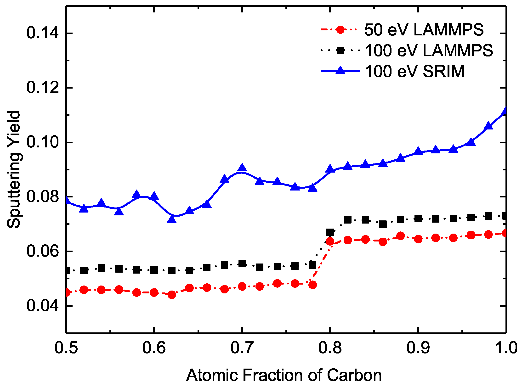
Figure 3.
The sputtering yield of SiC bulk with 62 at % C concentration as a function of the incident energy.
Figure 3.
The sputtering yield of SiC bulk with 62 at % C concentration as a function of the incident energy.

Figure 4.
Sputtering yield of SiC bulk with 62 at % C concentration as a function of the incident angle.
Figure 4.
Sputtering yield of SiC bulk with 62 at % C concentration as a function of the incident angle.

Figure 5.
Sputtering yield of SiC bulk with 62 at % C concentration as a function of its temperature.
Figure 5.
Sputtering yield of SiC bulk with 62 at % C concentration as a function of its temperature.
© 2018 by the authors. Licensee MDPI, Basel, Switzerland. This article is an open access article distributed under the terms and conditions of the Creative Commons Attribution (CC BY) license (http://creativecommons.org/licenses/by/4.0/).
Share and Cite
MDPI and ACS Style
Liang, X.; Li, Y.; Zhao, Q.; Zhang, Z.; Ouyang, X. Effect of Carbon Concentration on the Sputtering of Carbon-Rich SiC Bombarded by Helium Ions. Computation 2018, 6, 19. https://doi.org/10.3390/computation6010019
AMA Style
Liang X, Li Y, Zhao Q, Zhang Z, Ouyang X. Effect of Carbon Concentration on the Sputtering of Carbon-Rich SiC Bombarded by Helium Ions. Computation. 2018; 6(1):19. https://doi.org/10.3390/computation6010019
Chicago/Turabian StyleLiang, Xinghao, Yang Li, Qiang Zhao, Zheng Zhang, and Xiaoping Ouyang. 2018. "Effect of Carbon Concentration on the Sputtering of Carbon-Rich SiC Bombarded by Helium Ions" Computation 6, no. 1: 19. https://doi.org/10.3390/computation6010019
Note that from the first issue of 2016, this journal uses article numbers instead of page numbers. See further details here.