Evaluation of Polyethylene Glycol Diacrylate-Polycaprolactone Scaffolds for Tissue Engineering Applications

 ,
,
Abstract
:1. Introduction
2. Materials and Methods
2.1. Materials
2.2. Sample Preparation
2.2.1. Sample Design
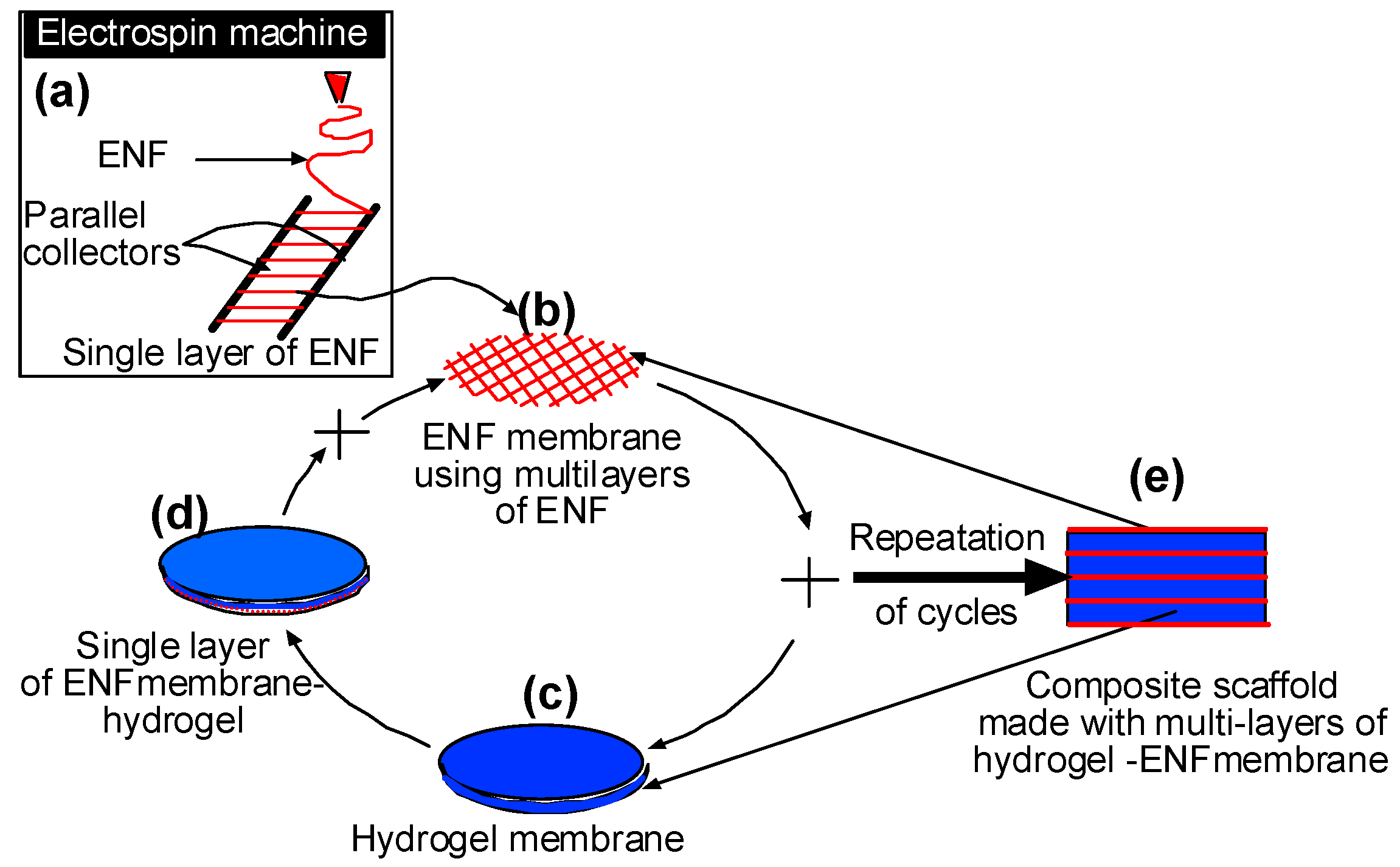
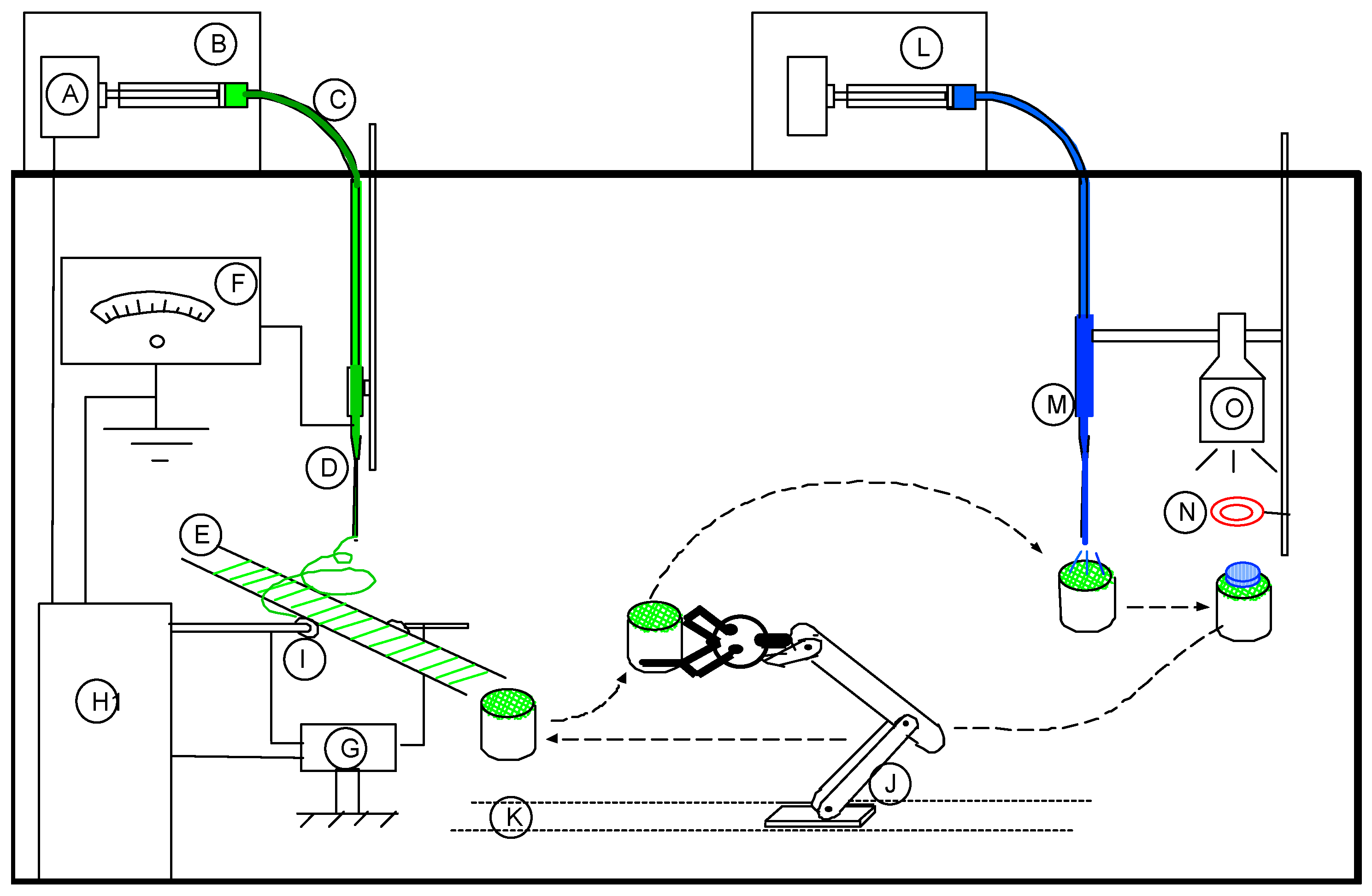
2.2.2. Sample Fabrication Process
2.3. Experiments
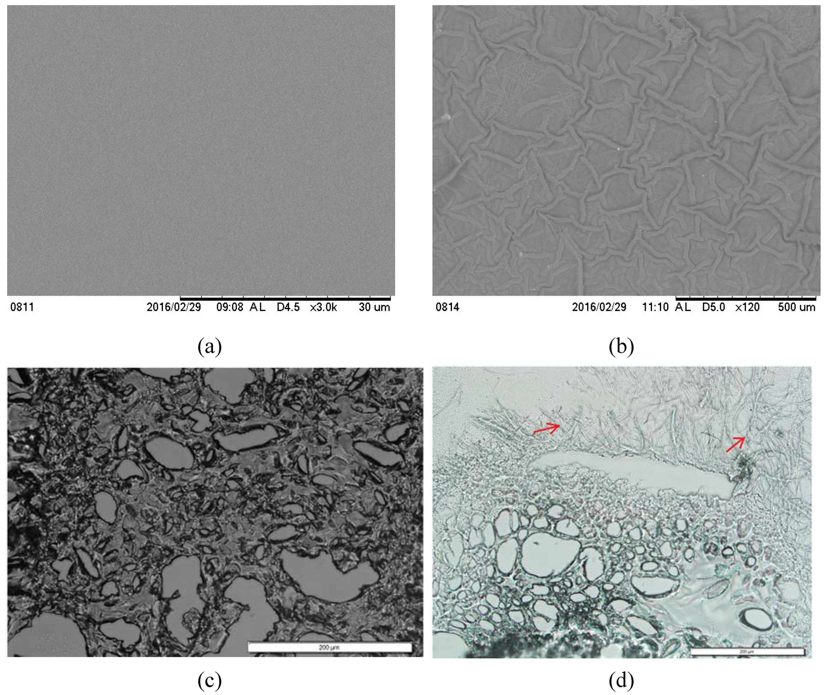
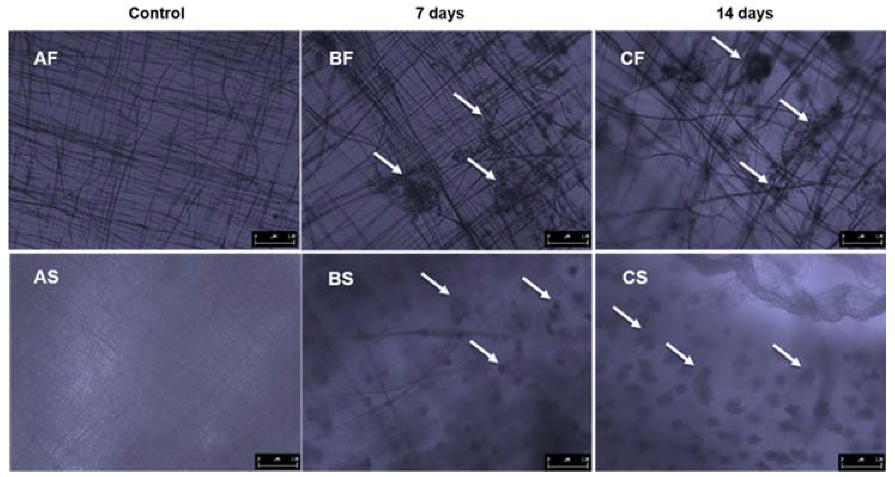
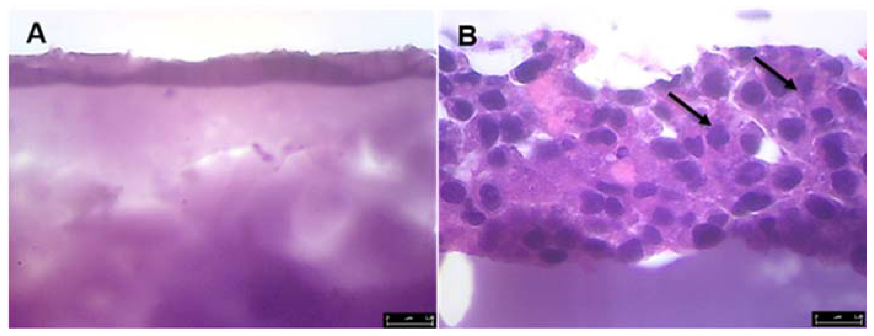
2.3.1. SEM and Histological Examination
2.3.2. Mechanical Tests
2.3.3. Bioactivity
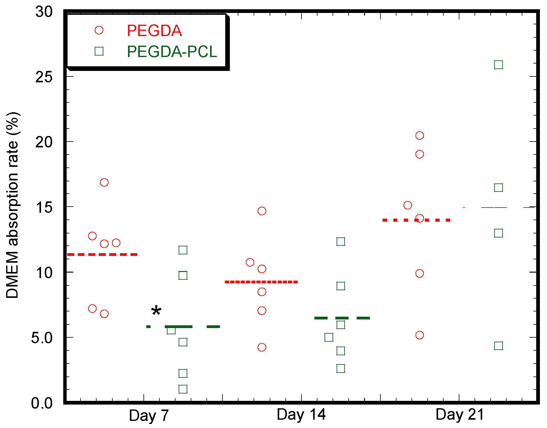
A. Absorption Test
B. Cell Cultures
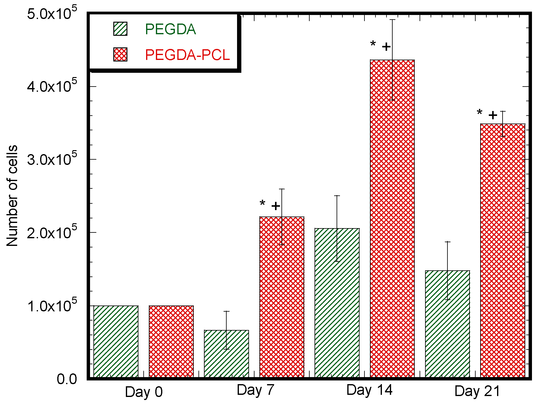
C. Cell Viability Assay
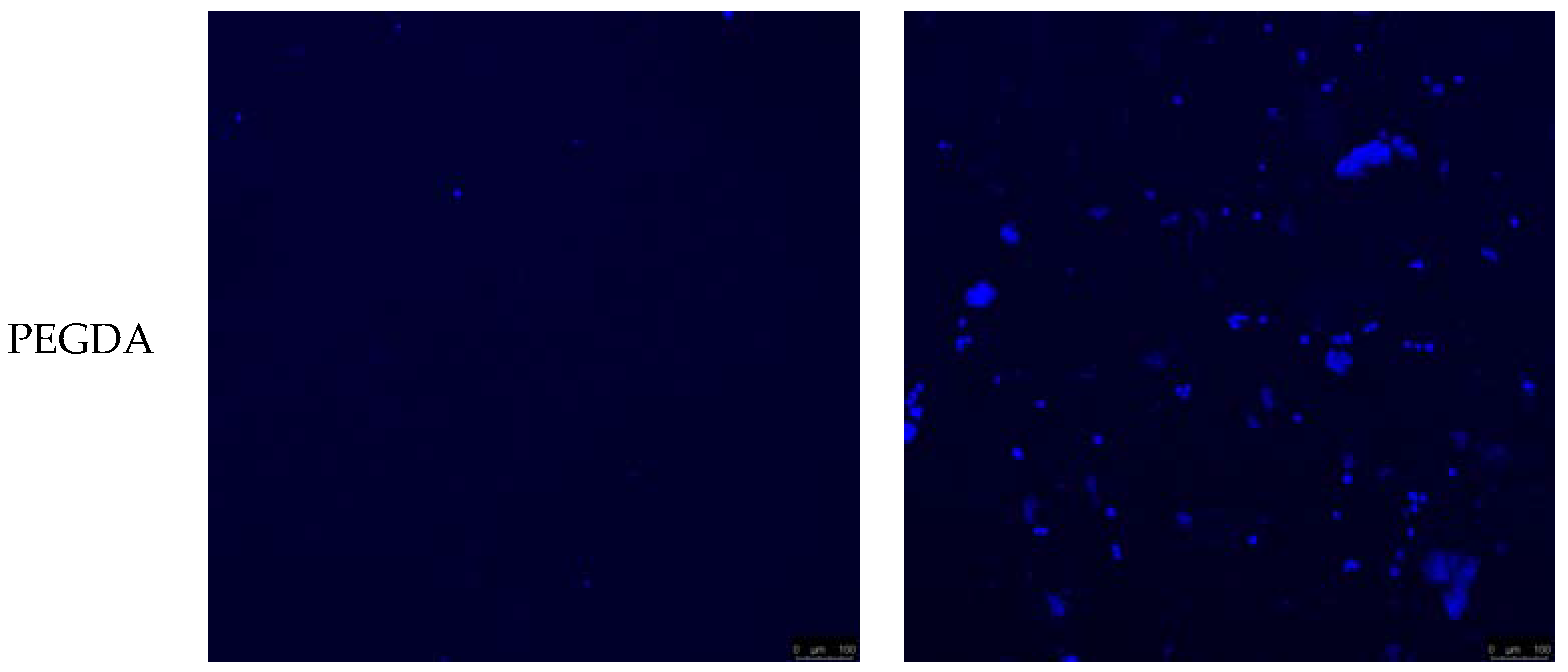
D. Microscopy and Staining
2.4. Statistical Analysis
3. Results
3.1. Fabrication of an Electrospinning Unit for the Production of PEGDA Scaffold
3.2. Surface Characterization
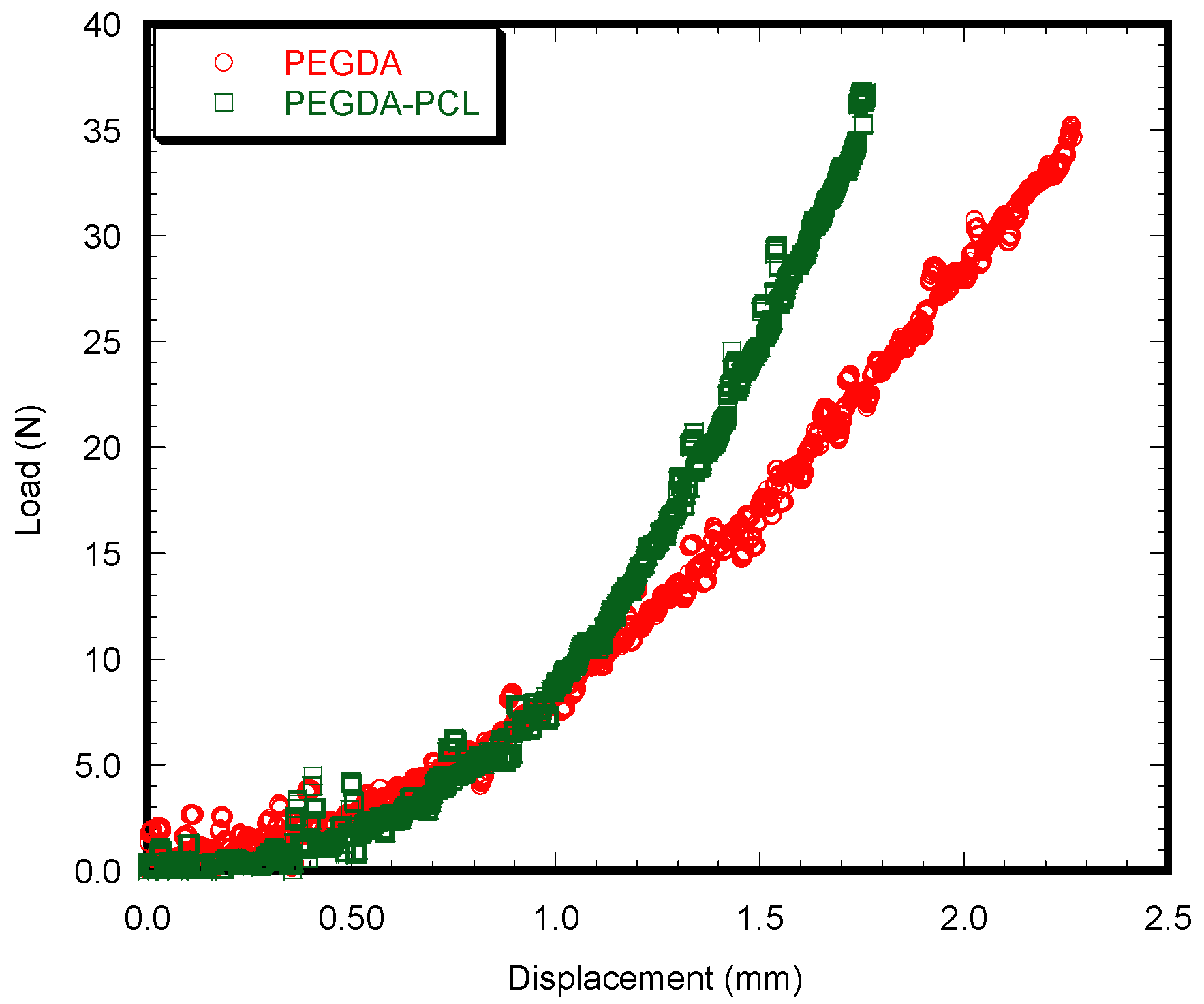
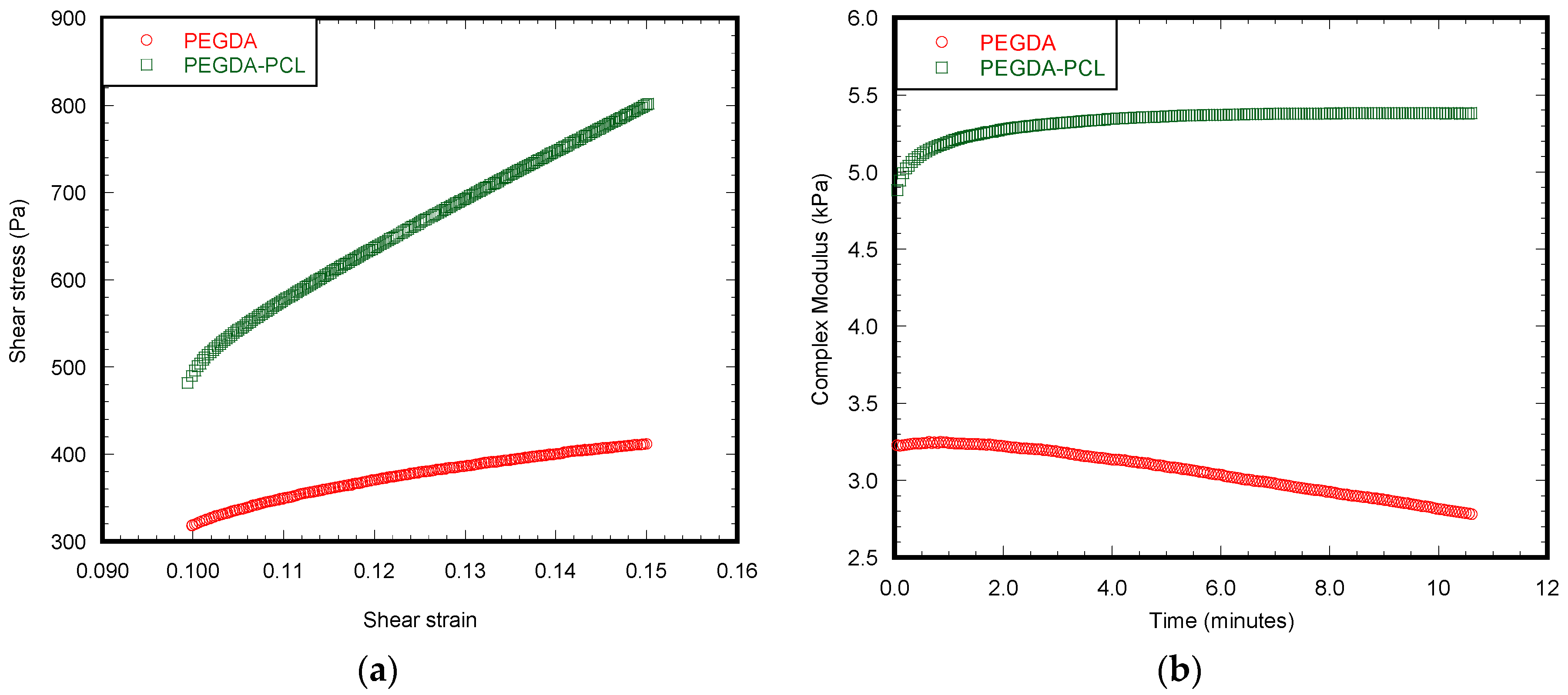
3.3. Mechanical Tests
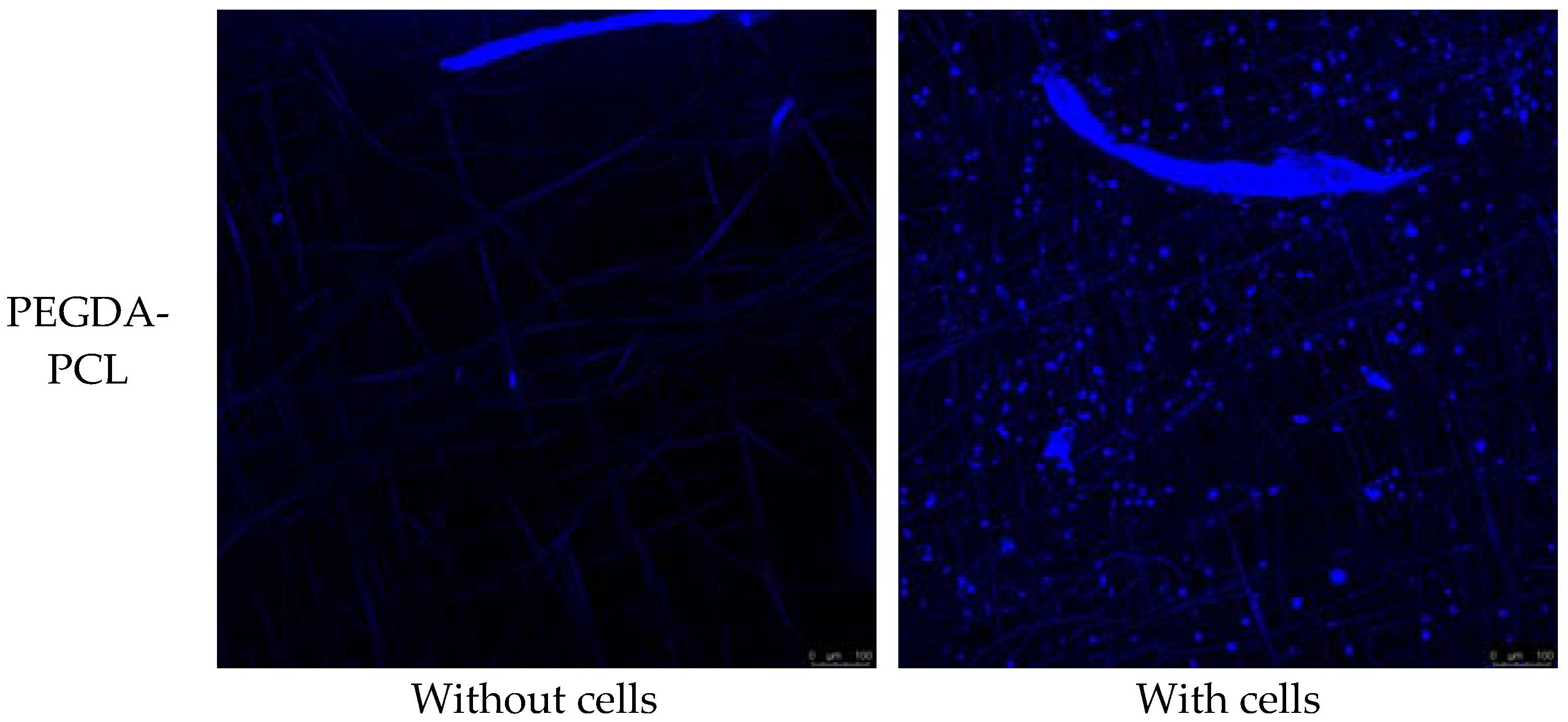
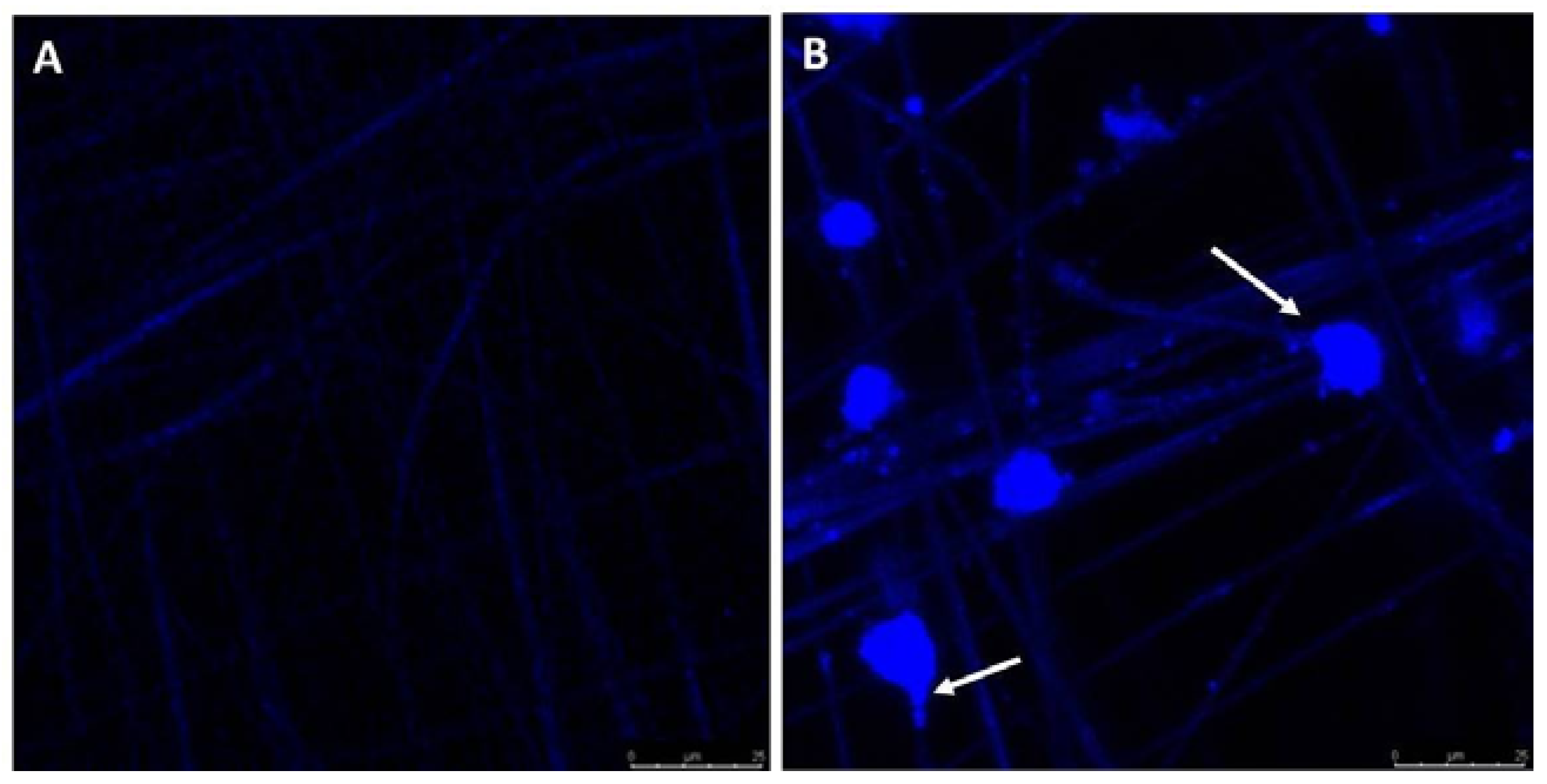
3.4. Bioactivity
4. Discussion
5. Conclusions
Acknowledgments
Author Contributions
Conflicts of interest
References
- Bosworth, L.A.; Turner, L.-A.; Cartmell, S.H. State of the art composites comprising electrospun fibres coupled with hydrogels: A review. Nanomed. Nanotechnol. Biol. Med. 2013, 9, 322–335. [Google Scholar] [CrossRef] [PubMed]
- Varghese, S.; Elisseeff, J.H. Hydrogels for musculoskeletal tissue engineering. In Polymers for Regenerative Medicine; Springer: Berlin/Heidelberg, Germany, 2006; pp. 95–144. [Google Scholar]
- Xin, A.X.; Gaydos, C.; Mao, J.J. In vitro degradation behavior of photopolymerized peg hydrogels as tissue engineering scaffold. In Proceedings of the IEEE Engineering in Medicine and Biology Society, New York, NY, USA, 30 August–3 September 2006; pp. 2091–2093. [Google Scholar]
- Yasar, O.; Orock, A.; Tarantini, S.; White, J.; Khandaker, M. Mechanical characterization of polyethylene glycol diacrylate (pegda) for tissue engineering applications. In Mechanics of Biological Systems and Materials; Prorok, B.C., Barthelat, F., Korach, C.S., Grande-Allen, K.J., Lipke, E., Lykofatitits, G., Zavattieri, P., Eds.; Springer: New York, NY, USA, 2013; Volume 5, pp. 189–195. [Google Scholar]
- Lee, K.Y.; Mooney, D.J. Hydrogels for tissue engineering. Chem. Rev. 2001, 101, 1869–1879. [Google Scholar] [CrossRef] [PubMed]
- Chen, F.; Tian, M.; Zhang, D.; Wang, J.; Wang, Q.; Yu, X.; Zhang, X.; Wan, C. Preparation and characterization of oxidized alginate covalently cross-linked galactosylated chitosan scaffold for liver tissue engineering. Mater. Sci. Eng. C 2012, 32, 310–320. [Google Scholar] [CrossRef]
- Khandaker, M.; Orock, A.; Tarantini, S.; White, J.; Yasar, O. Biomechanical performances of networked polyethylene glycol diacrylate: Effect of photoinitiator concentration, temperature, and incubation time. Int. J. Biomater. 2016, 2016, 3208312. [Google Scholar] [CrossRef] [PubMed]
- Sun, W.; Darling, A.; Starly, B.; Nam, J. Computer-aided tissue engineering: Overview, scope and challenges. Biotechnol. Appl. Biochem. 2004, 39, 29–47. [Google Scholar] [CrossRef] [PubMed]
- Yasar, O.; Starly, B.; Lan, S.-F. A lindenmayer systems based approach for the design of nutrient delivery networks in tissue constructs. J. Biofabr. 2009, 1, 045004. [Google Scholar] [CrossRef] [PubMed]
- Lee, S.-H.; Shin, H. Matrices and scaffolds for delivery of bioactive molecules in bone and cartilage tissue engineering. Adv. Drug Deliv. Rev. 2007, 59, 339–359. [Google Scholar] [CrossRef] [PubMed]
- Lenhert, S.; Meier, M.-B.; Meyer, U.; Chi, L.; Wiesmann, H.P. Osteoblast alignment, elongation and migration on grooved polystyrene surfaces patterned by langmuir–blodgett lithography. Biomaterials 2005, 26, 563–570. [Google Scholar] [CrossRef] [PubMed]
- Bonzani, I.C.; Adhikari, R.; Houshyar, S.; Mayadunne, R.; Gunatillake, P.; Stevens, M.M. Synthesis of two-component injectable polyurethanes for bone tissue engineering. Biomaterials 2007, 28, 423–433. [Google Scholar] [CrossRef] [PubMed]
- Visser, J.; Melchels, F.P.W.; Jeon, J.E.; van Bussel, E.M.; Kimpton, L.S.; Byrne, H.M.; Dhert, W.J.A.; Dalton, P.D.; Hutmacher, D.W.; Malda, J. Reinforcement of hydrogels using three-dimensionally printed microfibres. Nat. Commun. 2015, 6, 6933. [Google Scholar] [CrossRef] [PubMed]
- Abuabed, A.; Rankin, M.; Khandaker, M.; Forrer, M.; Bevel, W.; Varghese, S. An automated dual disc electrospun fiber collection method for sensing applications. In Proceedings of the 12th IEEE Sensors Applications Symposium, Glassboro, NJ, USA, 13–15 March 2017. [Google Scholar]
- Khandaker, M.; Riahinezhad, S. Process and apparatus to create 3d tissue scaffold using electrospun nanofiber matrix and photosensitive hydrogel. USA patent Application no 62/298,627, 2016. [Google Scholar]
- Chui, C.; Kobayashi, E.; Chen, X.; Hisada, T.; Sakuma, I. Combined compression and elongation experiments and non-linear modelling of liver tissue for surgical simulation. Med. Biolog. Eng. Comput. 2004, 42, 787–798. [Google Scholar] [CrossRef]
- Gloria, A.; Causa, F.; De Santis, R.; Netti, P.A.; Ambrosio, L. Dynamic-mechanical properties of a novel composite intervertebral disc prosthesis. J. Mater. Sci. Mater. Med. 2007, 18, 2159–2165. [Google Scholar] [CrossRef] [PubMed]
- Kerdok, A.E.; Ottensmeyer, M.P.; Howe, R.D. Effects of perfusion on the viscoelastic characteristics of liver. J. Biomech. 2006, 39, 2221–2231. [Google Scholar] [CrossRef] [PubMed]
- Rad, A.T.; Ali, N.; Kotturi, H.S.; Yazdimamaghani, M.; Smay, J.; Vashaee, D.; Tayebi, L. Conducting scaffolds for liver tissue engineering. J. Biomed. Mater. Res. A 2014, 102, 4169–4181. [Google Scholar] [PubMed]
- Yazdimamaghani, M.; Razavi, M.; Mozafari, M.; Vashaee, D.; Kotturi, H.; Tayebi, L. Biomineralization and biocompatibility studies of bone conductive scaffolds containing poly(3,4-ethylenedioxythiophene):Poly(4-styrene sulfonate) (pedot:Pss). J. Mater. Sci. Mater. Med. 2015, 26, 274. [Google Scholar] [CrossRef] [PubMed]
- Khandaker, M.; Snow, P. Method and Apparatus for Controlled Alignment and Deposition of Branched Electrospun Fiber. U.S. Patent 9,359,694, 7 June 2016. [Google Scholar]
- Sultana, F.; khandaker, M. Effect of architecture on the cell functions of an electrospun fiber membrane. In Mechanics of Biological Systems and Materials, 1st ed.; Korach, C.S., Tekalur, S.A., Zavattieri, P., Eds.; Springer International Publishing: New York, NY, USA, 2016; Volume 6. [Google Scholar]
- Feng, Z.Q.; Chu, X.; Huang, N.P.; Wang, T.; Wang, Y.; Shi, X.; Ding, Y.; Gu, Z.Z. The effect of nanofibrous galactosylated chitosan scaffolds on the formation of rat primary hepatocyte aggregates and the maintenance of liver function. Biomaterials 2009, 30, 2753–2763. [Google Scholar] [CrossRef] [PubMed]
- Kim, J.; Magno, M.H.; Waters, H.; Doll, B.A.; McBride, S.; Alvarez, P.; Darr, A.; Vasanji, A.; Kohn, J.; Hollinger, J.O. Bone regeneration in a rabbit critical-sized calvarial model using tyrosine-derived polycarbonate scaffolds. Tissue Eng. Part A 2012, 18, 1132–1139. [Google Scholar] [CrossRef] [PubMed]
- Khandaker, M.; Riahinezhad, S. Engineered Intervertebral Disc (ivd) for Degenerated Disc Disease. U.S. Patent Application No. 15/188,654, 21 June 2016. [Google Scholar]
- Zhao, X.; Irvine, S.A.; Agrawal, A.; Cao, Y.; Lim, P.Q.; Tan, S.Y.; Venkatraman, S.S. 3d patterned substrates for bioartificial blood vessels—The effect of hydrogels on aligned cells on a biomaterial surface. Acta Biomater. 2015, 26, 159–168. [Google Scholar] [CrossRef] [PubMed]
- Correia, T.R.; Ferreira, P.; Vaz, R.; Alves, P.; Figueiredo, M.M.; Correia, I.J.; Coimbra, P. Development of uv cross-linked gelatin coated electrospun poly(caprolactone) fibrous scaffolds for tissue engineering. Int. J. Biolog. Macromol. 2016, 93, 1539–1548. [Google Scholar] [CrossRef] [PubMed]
- Morris, V.B.; Nimbalkar, S.; Younesi, M.; McClellan, P.; Akkus, O. Mechanical properties, cytocompatibility and manufacturability of chitosan:Pegda hybrid-gel scaffolds by stereolithography. Ann. Biomed. Eng. 2017, 45, 286–296. [Google Scholar] [CrossRef] [PubMed]
- Shanjani, Y.; Pan, C.C.; Elomaa, L.; Yang, Y. A novel bioprinting method and system for forming hybrid tissue engineering constructs. Biofabrication 2015, 7, 045008. [Google Scholar] [CrossRef] [PubMed]


| Experimental Parameters | PEGDA | PEGDA-PCL |
|---|---|---|
| Compressive stiffness (N/mm) | 3.00 ± 0.12 | 5.36 ± 0.02 * |
| Compressive modulus (kPa) | 259.68 ± 3.56 | 509.61 ± 0.01 * |
| Experimental Parameters | PEGDA Only | PEGDA-PCL |
|---|---|---|
| Viscous modulus (kPa) | 1.01 ± 0.24 | 0.53 ± 0.18 * |
| Elastic modulus (kPa) | 2.82 ± 0.12 | 5.34 ± 0.23 * |
| Phase shift angle (degree) | 19.72 ± 0.40 | 5.68 ± 0.22 * |
© 2017 by the authors. Licensee MDPI, Basel, Switzerland. This article is an open access article distributed under the terms and conditions of the Creative Commons Attribution (CC BY) license (http://creativecommons.org/licenses/by/4.0/).
Share and Cite
Kotturi, H.; Abuabed, A.; Zafar, H.; Sawyer, E.; Pallipparambil, B.; Jamadagni, H.; Khandaker, M. Evaluation of Polyethylene Glycol Diacrylate-Polycaprolactone Scaffolds for Tissue Engineering Applications. J. Funct. Biomater. 2017, 8, 39. https://doi.org/10.3390/jfb8030039
Kotturi H, Abuabed A, Zafar H, Sawyer E, Pallipparambil B, Jamadagni H, Khandaker M. Evaluation of Polyethylene Glycol Diacrylate-Polycaprolactone Scaffolds for Tissue Engineering Applications. Journal of Functional Biomaterials. 2017; 8(3):39. https://doi.org/10.3390/jfb8030039
Chicago/Turabian StyleKotturi, Hari, Alaeddin Abuabed, Haris Zafar, Elaine Sawyer, Bipin Pallipparambil, Harsha Jamadagni, and Morshed Khandaker. 2017. "Evaluation of Polyethylene Glycol Diacrylate-Polycaprolactone Scaffolds for Tissue Engineering Applications" Journal of Functional Biomaterials 8, no. 3: 39. https://doi.org/10.3390/jfb8030039