Article

Preparation and Characteristics of SiOx Coated Carbon Nanotubes with High Surface Area

1
Fuel Cell Research Center, Korea Institute of Energy Research, Daejeon 305-343, Korea
2
Advanced Energy Technology, University of Science & Technology, Daejeon 305-350, Korea
*
Author to whom correspondence should be addressed.
Nanomaterials 2012, 2(2), 206-216; https://doi.org/10.3390/nano2020206
Submission received: 2 May 2012 / Revised: 8 June 2012 / Accepted: 11 June 2012 / Published: 18 June 2012
(This article belongs to the Special Issue New Developments in Nanomaterial Analysis)

Abstract

:
An easy method to synthesize SiOx coated carbon nanotubes (SiOx-CNT) through thermal decomposition of polycarbomethylsilane adsorbed on the surface of CNTs is reported. Physical properties of SiOx-CNT samples depending on various Si contents and synthesis conditions are examined by X-ray diffraction (XRD), X-ray photoelectron spectroscopy (XPS), nitrogen isotherm, scanning electron microscope (SEM), and transmission electron microscope (TEM). Morphology of the SiOx-CNT appears to be perfectly identical to that of the pristine CNT. It is confirmed that SiOx is formed in a thin layer of approximately 1 nm thickness over the surface of CNTs. The specific surface area is significantly increased by the coating, because thin layer of SiOx is highly porous. The surface properties such as porosity and thickness of SiOx layers are found to be controlled by SiOx contents and heat treatment conditions. The preparation method in this study is to provide useful nano-hybrid composite materials with multi-functional surface properties.

1. Introduction

Hybrid materials combining carbon nanotubes (CNT) with the oxides have been synthesized to obtain improved or sometimes new functions in various applications. For example, TiO2-CNT hybrids in electrocatalysis have been reported to increase catalytic activity of platinum and its CO-tolerance for alcohol electro-oxidation [1]. In gas sensors, SnO2-CNT hybrids improved response and recovery by combining instinct electrical properties of SnO2 and excellent adsorption properties of CNT having high surface area [2,3,4,5,6], and ZnO-CNT hybrids shown higher photocatalytic activity than ZnO bulk material by combining advantages of ZnO, such as high optical activity and high sensitivity for UV-Vis light, and advantages of CNT, such as high mechanical strength and chemical stability [7]. In addition, the oxide-CNT hybrids were applied in supercapacitors (MnO2) and field emission (MgO) [8,9]. SiO2-CNT hybrids have been prepared for various applications such as oxidation resistance, optic applications, biosensor and catalytic applications due to their high surface area and versatility of silica chemistry [10,11,12].
Generally, activation of carbons is to increase porosity and attach functional groups over their surface through partly destroying their structure. Especially, CNT, which has the basal surface (less reactive than the graphitic edges), is required to be activated in harsh conditions such as chemical oxidation using strong acid such as HNO3, H2SO4, and KMnO4 [13,14,15,16,17]. Chemical oxidation is a very effective way to increase the solubility and chemical reactivity, as well as the porosity and surface area [18,19]. However, the defects formed by such treatments can lessen the superior mechanical and electronic properties of CNT [20].
In this study, a surface modification was carried out through coating SiOx over CNT, which might be an efficient way to functionalize the CNT surface without making structural defects. SiOx-CNT composites were synthesized using a simple method with adsorption of hydrophobic silicon containing polymer on the CNT surfaces and then thermal decomposition under prescribed conditions.

2. Experimental Section

2.1. Chemicals

The CNT sample used in this study is a multi-wall type (diameter 10–40 nm, purity 95%), purchased from CNT Co., Ltd. Polycarbomethylsilane (MW~800) was purchased from Sigma-Aldrich Co., and tetrahydrofuran (THF) was obtained from SAMCHUN chemicals.

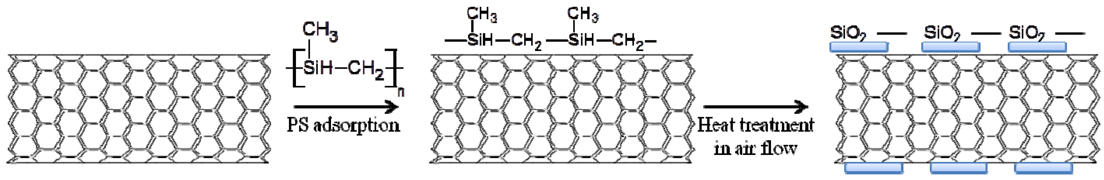
2.2. Preparation of SiOx-CNT

Figure 1 shows schematically the preparation process of SiOx-CNT samples. Polycarbomethylsilane (PS), which is a silicon-containing polymer, was used as the SiOx precursor. PS of 1 g was completely dissolved in 150 mL THF under vigorous stirring at room temperature for 30 min. CNTs were added into the solution, which was stirred for 15 h. The mixtures were shortly sonicated, and then the solvent was removed, using a rotary evaporator under reduced pressure at 35 °C, and the mixture powder was dried in an oven at 80 °C over 12 h.
SiOx-CNT was obtained through thermal decomposition of PS-CNT mixture. The heat treatment carried out at different temperature (300 °C, 400 °C, 500 °C, and 700 °C) in an air atmosphere fed at a rate of 200 cm3/min. Heating rate was 5 °C/min and at set point temperatures maintained for 2 h.
The names of the samples were defined as SCm0n (m: ratio of CNTs, n: the hundred digit of heat treatment temperatures). The ratio (weight) of CNT to PS is fixed to “n:1”. For example, “SC103” is prepared from the precursor ratio of CNT to PS, 1:1 (w/w) at 300 °C.
Figure 1. Schematic diagram of the SiOx coated carbon nanotubes (SiOx-CNT) preparation by Polycarbomethylsilane (PS) coating and heat treatment.
Nanomaterials 02 00206 g001

2.3. Characterization

Thermal gravimetric analysis (TGA) was examined, using STA409PC (NETZSCH). The temperature range was from 25 °C to 900 °C with a constant heating rate of 5 °C/min in air flow.
The morphology of samples was characterized by SEM (S-4700, Hitachi) and TEM (Tecnai F20, Philips). For TEM measurement, very small quantity of the samples was dispersed in ethanol solution and the solution was sonicated for 5 min. The well-dispersed suspension was dropped onto a TEM grid.
The specific surface areas and pore parameters were obtained by analyzing the nitrogen adsorption-desorption isotherms recorded at 77 K using a surface area analyzer (BELSORP-mini, BEL JAPAN INC.). Prior to this measurement, the samples were degassed at 250 °C for 3 h. The pore size was analyzed from the desorption isotherm using the BJH (Barrett-Joyner-Halenda) method.
XRD (RINT2000, Rigaku) was carried out to investigate the graphitic structure of CNT before and after SiOx coating with heat treatment at various temperatures. Scans were done for 2θ values between 10 °C and 90 °C at 5 °C/min. To inspect chemical states of silicon and carbon in SiOx-CNT composites, XPS (AXIS NOVA, KRATOS) was also performed.

3. Results and Discussion

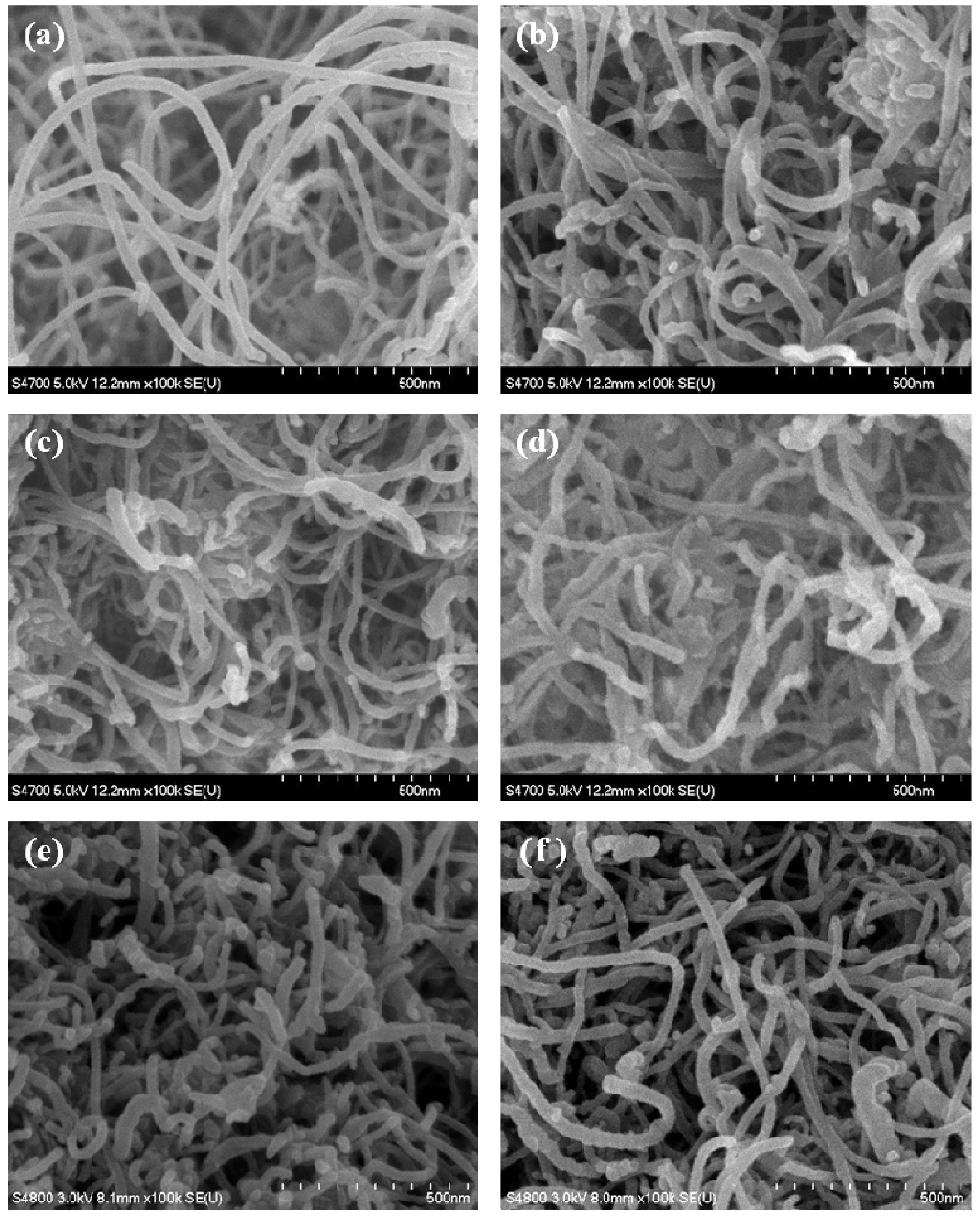
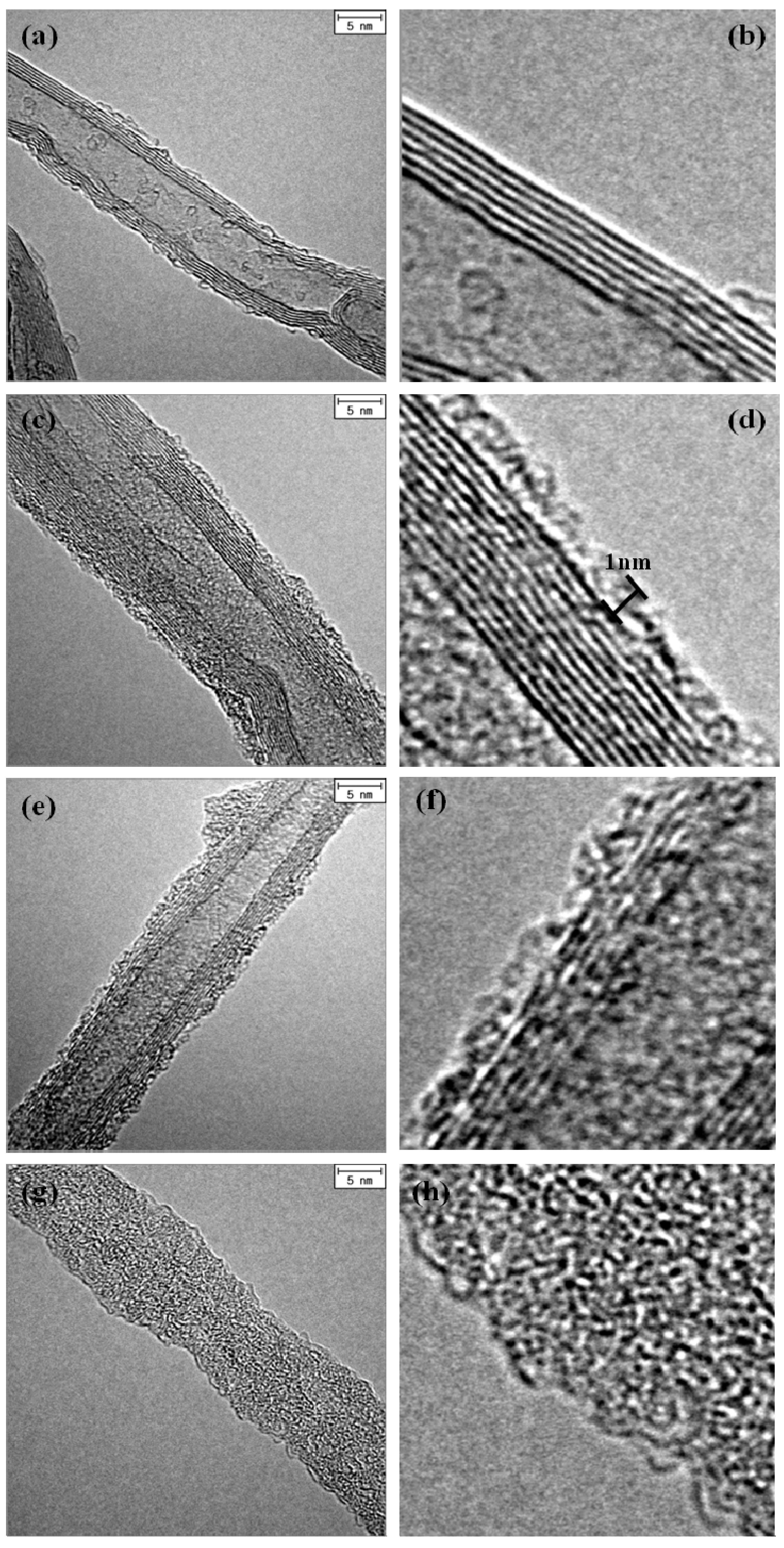
3.1. Morphology of SiOx-CNT Composites

Figure 2 shows SEM images of CNTs and various SiOx-CNT samples. Figure 2a shows an image of pristine CNTs, and clearly indicates a structural feature of CNTs having thin tube shape. As shown in Figure 2b,c,e,f, the morphology of SiOx-CNT samples appear to be almost similar with the pristine CNT, despite of SiOx coating. When CNT was completely combusted at 700 °C in air (sample SC107), appearance of the sample was also almost the same as pristine CNT, and any noticeable silica particulates or aggregates were not found under SEM (Figure 2d). It indicates that PS is uniformly coated over the whole CNT surface, resulting in silica nanotubes with the same dimensions as CNT.
Figure 2. SEM images of (a) pristine CNTs, (b) SC104, (c) SC105, (d) SC107, (e) SC204, and (f) SC304.
Nanomaterials 02 00206 g002
The structure of the samples was observed by TEM, examining SiOx layers on the CNT. Figure 3 shows TEM images of original CNTs and various SiOx-CNT samples treated at different temperatures. For the pristine CNT (Figure 3a,b), and several graphitic layers were confirmed to be well arranged in a manner of concentric cylinders with a clean surface overall. In SiOx-CNT samples, an additional layer, which has an amorphous structure, is found on the CNT surface, as shown in Figure 3c–f. The amorphous layer spreads over the CNT surface with an approximate thickness of 1 nm, although it is not perfectly uniform. The graphitic layers of CNT in the SiOx-CNT samples appear to be straight-aligned and almost intact. Decrease of the image resolution for the graphitic layers in Figure 3d,f is probably due to the SiOx layer over the CNT surface. In Figure 3g,h, SiOx nanotubes with amorphous structure were confirmed, and their geometrical morphology in TEM images appears to be identical to the pristine CNT, as observed in SEM (Figure 2d).
Figure 3. TEM images of (a,b) pristine CNTs, (c,d) SC103, (e,f) SC104, (g,h) SC107.
Nanomaterials 02 00206 g003

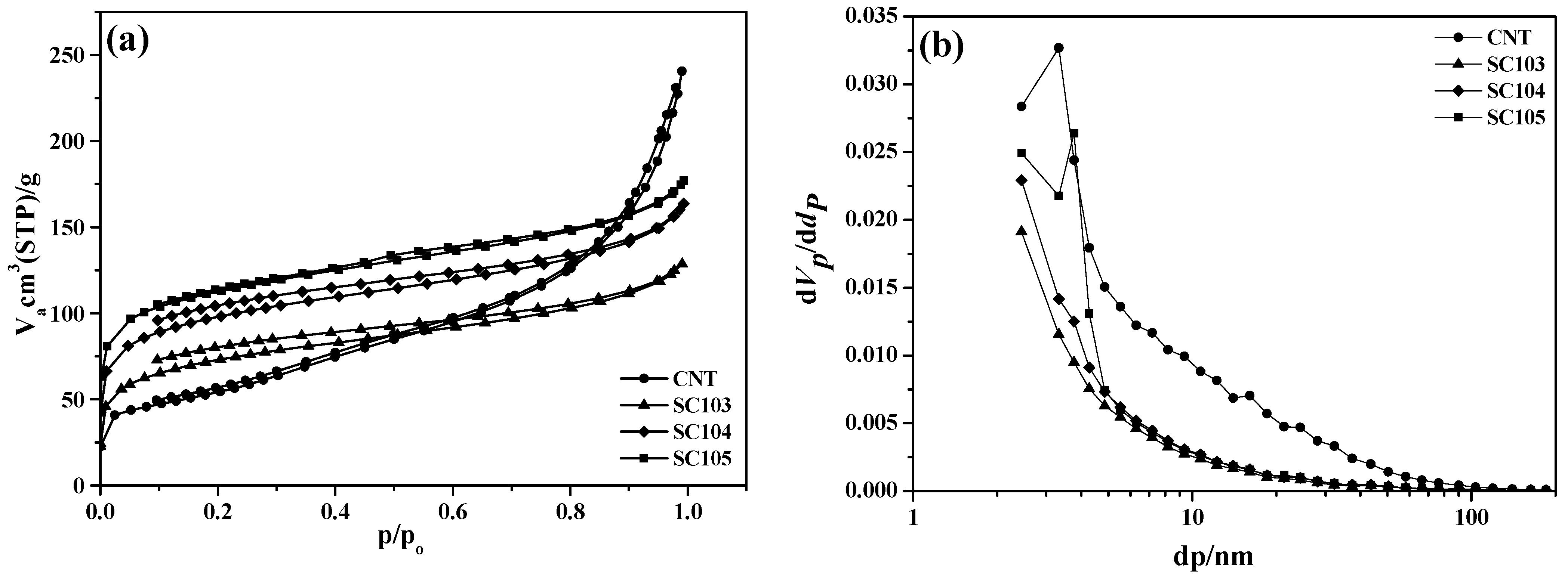
3.2. Surface Properties of SiOx-CNT

The sample preparation, specific surface area and pore volume are summarized in Table 1. The contents of CNT and SiOx in these samples were evaluated using TG under an air atmosphere through complete combustion of CNT. Specific surface area and total pore volume were calculated from the nitrogen adsorption/desorption isotherms. The surface area as well as pore volume increases as the temperature increases. In case of the sample SC105, the specific surface area is approximately two times higher than that of the pristine CNT. As the Si content decreases (SC20m and SC30m series), the increase of the specific surface area tends to be reduced, but it shows still higher (1.6 times at least for the samples heat-treated at 500 °C) than that of the pristine. Hence, formation of new porosity must be caused by silicon oxide species coated on CNT, and it can be controlled by the heat treatment conditions and the Si compositions.
Table 1. Surface properties and the contents of SiOx in SiOx-CNT samples.
SampleContent (wt %)Heat treatment conditionsSpecific surface area (m2/g)Total pore volume (cm3/g)
SiOxCNT
CNT01001980.372
SC10348.851.2300 °C, air, 2h2610.199
SC10448.851.2400 °C, air, 2h3520.253
SC10548.851.2500 °C, air, 2h4050.273
SC1071000700 °C, air, 2h6710.768
SC20332.167.9300 °C, air, 2h2140.317
SC20432.167.9400 °C, air, 2h3150.388
SC20532.167.9500 °C, air, 2h3350.357
SC30326.923.1300 °C, air, 2h2200.344
SC30426.923.1400 °C, air, 2h2500.384
SC30526.923.1500 °C, air, 2h3280.434
Figure 4 shows nitrogen isotherm profiles and corresponding pore size distribution of pristine CNT and SiOx-CNT samples synthesized according to the heat treatment temperatures. From the low relative pressure (below p/p0 0.1), micropores are confirmed to increase, probably originating from silicon species. The increase of porosity according to increase of temperature, might reflect progress of thermal decomposition of PS and at the same time formation of micropores. The adsorption/desorption isotherm profile of the pristine CNT is of the type II in the IUPAC classification, which is as obtained from a non-porous or macroporous adsorbent [21]. For SiOx-CNT samples, the type of isotherm profiles is found to change to that of type I, which corresponds to that of microporous solid. Comparing CNT with SC10m series, the total pore volume decreased with the silicon species coating, although the specific surface area increased. Hence, the porosity of SiOx-CNT samples must be dominated by silicon species. It is highly-microporous.
From the pore size distribution (Figure 4b), the level of large pore volume over 10 nm appears to be higher in the pristine CNT than in SiOx-CNT samples. The large pore of the CNT sample must originate from inter-space formed in an agglomerate of entangled nanotubes, because their diameters are around 10 nm. The low level of such a large pore volume in SiOx-CNT samples indicates that such an agglomeration is disassembled to some degree during the preparation procedure such as coating PS in the solution or heat treatment. The surface coating may be effective for dispersion of CNT, although there is not sufficient proof at present.
Figure 4. (a) Nitrogen isotherm and (b) pore size distribution curve of SiOx-CNT samples (48.8 wt % SiOx) treated at different temperatures (300 °C, 400 °C, 500 °C).
Nanomaterials 02 00206 g004

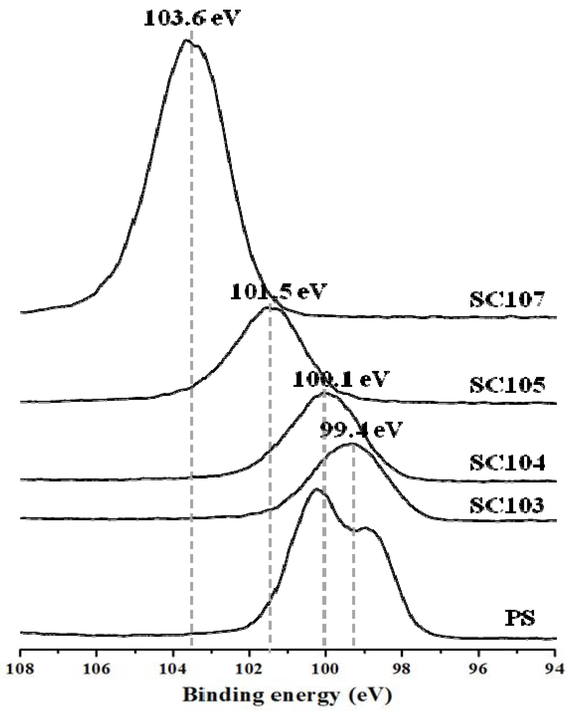
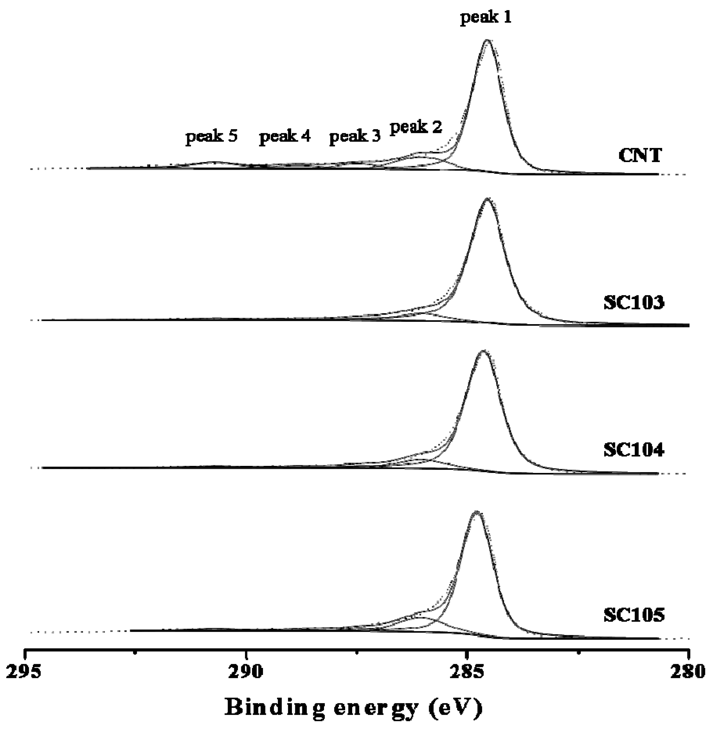
3.3. XPS Analysis of the Chemical Status of the SiOx-CNT Composites

XPS analysis of SiOx-CNT composites was performed to examine the oxidation state of silicon (Figure 5) and carbon (Figure 6) on the surface. Figure 5 shows Si-2p spectra of PS and SiOx-CNT treated at different temperatures. Binding energy of Si 2p indicates the oxidation state of Si atom such as Si0+SiH (99.4 eV), Si1+ (100.3 eV), Si2+ (101.2 eV), Si3+ (102.0 eV), and Si4+ (103.0 eV) [22]. Si-2p peaks of SiOx-CNT were positively shifted from 99.4 eV to 103.5 eV by increasing treatment temperature. Si atom was partly oxidized to SiOx (x < 2) below 500 °C for 2 h, while it was fully oxidized to SiO2 at 700 °C. Specifically, the silicon atoms in the sample prepared at 300 °C have still direct bond to alkyl moiety, not yet to be oxidized, and those of SC104 is slightly oxidized, being close to the state of Si1+. For the sample prepared at 500 °C, the oxidation number of silicon atoms ranges from 2+ to 3+. Considering the silicon oxidation state with the surface area and porosity (Table 1 and Figure 4), the more oxidation proceeds, the more pores are formed. Hence, micropores of SiOx-CNT composites must stem from thermal decomposition of alkyl moieties and rearrangement of silicon species to oxides.
Figure 6 shows C-1s core level spectra of CNT and SiOx-CNT composites, which are deconvoluted to five categories of carbon oxidation states. The peak 1 (284.6 eV) indicates to graphitic carbons, and peak 2 (286.1–286.3 eV) represents carbon in alcohol or ether groups, peak 3 (287.6–287.7 eV) in carbonyl groups, peak 4 (288.6–289.0 eV) in carboxyl or ester groups, and peak 5 (290.6–290.7 eV) in carbonate groups [23]. Profiles of SiOx-CNT were rather similar to pristine CNT, which means that the graphitic structure in CNT is almost intact after preparation of SiOx-CNT composites. Rather, oxygen functional groups in SC103 and 104 appear to reduce compared to pristine CNT as a result of the decomposition of oxygen functional groups by heat treatment. Whereas, in the case of the SC105 sample, the intensity of peak 2 increases slightly compared to that of CNT, indicating that the CNT surface may be slightly oxidized at 500 °C.
Figure 5. Si-2p XPS profiles of PS and SiOx-CNT samples.
Nanomaterials 02 00206 g005
Figure 6. C-1s XPS profiles of CNT and SiOx-CNT samples.
Nanomaterials 02 00206 g006
In this study, effects of heat treatment time have yet to be examined, but the oxidation state of silicon atoms is expected to be further controlled by long-time annealing under prescribed conditions.

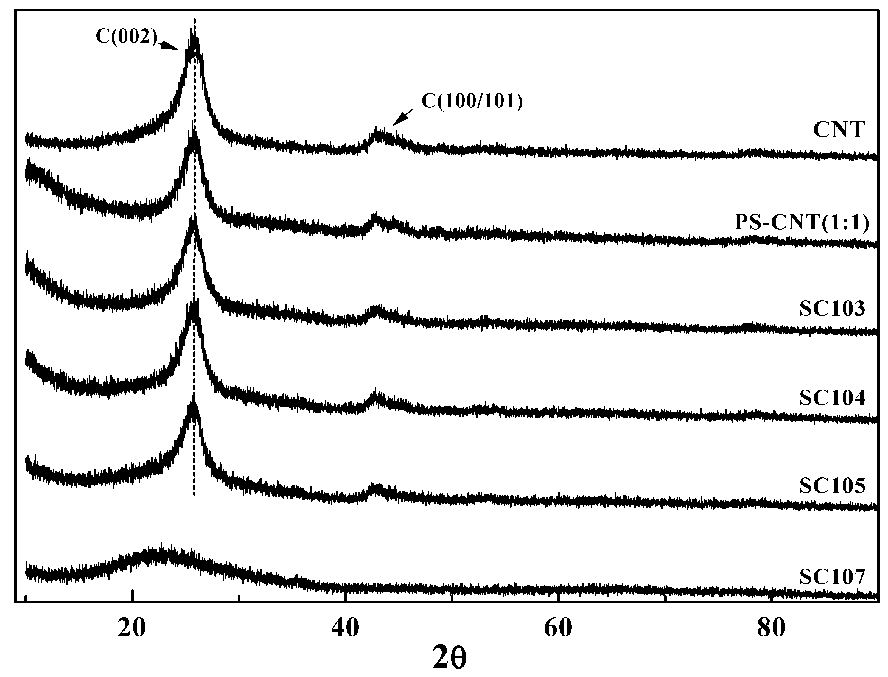
3.4. XRD Analysis of the SiOx-CNT Composites

Figure 7 shows the X-ray diffraction profiles of CNTs, PS-CNT and SiOx-CNT treated at 300 °C, 400 °C, 500 °C and 700 °C. In an XRD profile of SC107 sample (100 wt % silica), a peak of amorphous silica was observed at around 25° [24]. It was confirmed from these results that amorphous SiOx layers were formed on the CNT surfaces during the heat decomposition and amorphous peak of SiOx overlapped with the peak of carbon (002) phase. XRD profiles of SiOx-CNT samples however are similar to those of CNT. It reflects that the CNT structure in SiOx-CNT remains intact without structural defects, which is identical to the results of C-1s XPS results (Figure 6).
Figure 7. XRD profiles of CNT, PS-CNT and the SiOx-CNT according to treatment temperature.
Nanomaterials 02 00206 g007

4. Conclusions

SiOx-CNT composites, which consist of CNT at the core and silicon oxide species on the surface, were successfully synthesized by a simple method of thermal decomposition of PS-coated CNT. The hydrophobic PS might be effective to spread uniformly over the surface CNT. Morphology of SiOx-CNT composites was nearly identical with the pristine CNT, and the thickness of silicon oxide species was about 1 nm. SiOx-CNT composites showed higher specific surface area (over double) than the pristine CNT, and their porosity was found to be controlled by selection of heat treatment conditions and Si/C ratio. The CNT structure in the composites appeared to be intact after the preparation, as confirmed by XPS and XRD. Application of the SiOx-CNT hybrid materials to electrodes or catalyst supports for polymer electrolyte fuel cells is in progress; anticipating high surface area for dispersion of catalysts, increased oxidation resistance under electrochemically corrosive environment, and also improved metal-support interaction.

Acknowledgments

The work was carried out under the frame of Creative Technology Development Program in Korea Institute of Energy Research.

References

  1. Song, H.; Qiu, X.; Li, F.; Zhu, W.; Chen, L. Ethanol electro-oxidation on catalysts with TiO2 coated carbon nanotubes as support. Electrochem. Commun. 2007, 9, 1416–1421. [Google Scholar] [CrossRef]
  2. Chen, Y.; Zhu, C.; Wang, T. The enhanced ethanol sensing properties of multi-walled carbon nanotubes/SnO2 core/shell nanostructures. Nanotechnol. 2006, 17, 3012–3017. [Google Scholar] [CrossRef]
  3. Varghese, O.K.; Kichambre, P.D.; Gong, D.; Ong, K.G.; Dickey, E.C.; Grimes, C.A. Gas sensing characteristics of multi-wall carbon nanotubes. Sens. Actuators B Chem. 2001, 81, 32–41. [Google Scholar] [CrossRef]
  4. Collins, P.G.; Bradley, K.; Ishigami, M.; Zettl, A. Extreme oxygen sensitivity of electronic properties of carbon nanotubes. Science 2000, 287, 1801–1804. [Google Scholar]
  5. Sinha, N.; Ma, J.; Yeow, J.T.W. Carbon nanotube-based sensors. J. Nanosci. Nanotechnol. 2006, 6, 573–590. [Google Scholar]
  6. Kong, J.; Franklin, N.R.; Zhou, C.; Chapline, M.G.; Peng, S.; Cho, K.; Dai, H. Nanotube molecular wires as chemical sensors. Science 2000, 287, 622–625. [Google Scholar]
  7. Jiang, L.; Gao, L. Fabrication and characterization of ZnO-coated multi-walled carbon nanotubes with enhanced photocatalytic activity. Mater. Chem. Phys. 2005, 91, 313–316. [Google Scholar] [CrossRef]
  8. Gong, K.P.; Yu, P.; Su, L.; Xiong, S.X.; Mao, L.Q. Polymer-assisted synthesis of manganese dioxide/carbon nanotube nanocomposite with excellent electrocatalytic activity toward reduction of oxygen. J. Phys. Chem. C 2007, 111, 1882–1887. [Google Scholar]
  9. Pan, L.; Konishi, Y.; Tanaka, H. Effect of MgO coating on field emission of a stand-alone carbon nanotube. J. Vac. Sci. Technol. B 2007, 25, 1581–1583. [Google Scholar] [CrossRef]
  10. Bourlinos, A.B.; Georgakilas, V.; Zboril, R.; Dallas, P. Preparation of a water-dispersible carbon nanotube-silica hybrid. Carbon 2007, 45, 2136–2139. [Google Scholar] [CrossRef]
  11. Bottini, M.; Tautz, L.; Huynh, H.; Monosov, E.; Bottini, N.; Dawson, M.I.; Bellucci, S.; Mustelin, T. Covalent decoration of multi-walled carbon nanotubes with silica nanoparticles. Chem. Commun. 2005, 6, 758–760. [Google Scholar]
  12. Riggs, J.E.; Walker, D.B.; Carroll, D.L.; Sun, Y.P. Optical limiting properties of suspended and solubilized carbon nanotubes. J. Phys. Chem. B 2000, 104, 7071–7076. [Google Scholar]
  13. Tasis, D.; Tagmatarchis, N.; Bianco, A.; Prato, M. Chemistry of nanotube. Chem. Rev. 2006, 106, 1105–1136. [Google Scholar]
  14. Hou, P.X.; Liu, C.; Cheng, H.M. Purification of carbon nanotubes. Carbon 2008, 46, 2003–2025. [Google Scholar] [CrossRef]
  15. Balasubramanian, K.; Burghard, M. Chemically functionalized carbon nanotubes. Small 2005, 2, 180–192. [Google Scholar] [CrossRef]
  16. Gojny, F.H.; Nastalczyk, J.; Roslaniec, Z.; Schulte, K. Surface modified multi-walled carbon nanotubes in CNT/epoxy composites. Chem. Phys. Lett. 2003, 370, 820–824. [Google Scholar] [CrossRef]
  17. Liu, L.; Qin, Y.; Guo, Z.X.; Zhu, D. Reduction of solubilized multi-walled carbon nanotubes. Carbon 2003, 41, 331–335. [Google Scholar] [CrossRef]
  18. Fu, K.F.; Sun, Y.P. Dispersion and solubilization of carbon nanotubes. J. Nanosci. Nanotechnol. 2003, 3, 351–364. [Google Scholar] [CrossRef]
  19. Tasis, D.; Tagmatarchis, N.; Georgakilas, V.; Prato, M. Soluble carbon nanotubes. Chem. Eur. J. 2003, 9, 4000–4008. [Google Scholar] [CrossRef]
  20. Shallenberger, J.R. Determination of chemistry and microstructure in SiOx (0.1 < x < 0.8) films by X-ray photoelectron spectroscopy. J. Vac. Sci. Technol. A 1996, 14, 693–698. [Google Scholar] [CrossRef]
  21. Sing, K.S.W.; Everett, D.H.; Haul, R.A.W.; Moscou, L.; Pierotti, R.A.; Rouquerol, J.; Siemieniewska, T. Reporting physisorption data for gas/solid systems with special reference to the determination of surface area and porosity. Pure Appl. Chem. 1985, 57, 603–619. [Google Scholar] [CrossRef]
  22. Salzmann, C.G.; Llewellyn, S.A.; Tobias, G.; Ward, M.A.H.; Huh, Y.; Green, M.L.H. The role of carboxylated carbonaceous fragments in the functionalization and spectroscopy of a single-walled carbon-nanotube material. Adv. Mater. 2007, 19, 883–887. [Google Scholar]
  23. Gardner, S.D.; Singamsetty, C.S.K.; Booth, G.L.; He, G.; Pittman, C.U. Surface characterization of carbon fibers using angle-resolved XPS and ISS. Carbon 1995, 33, 587–595. [Google Scholar] [CrossRef]
  24. Wang, X.; Miao, X.; Li, Z.; Deng, W. Fabrication of mesoporous silica hollow spheres using triblock copolymer PEG–PPG–PEG as template. J. Non-Cryst. Solids 2010, 356, 898–905. [Google Scholar]

