
Highly-Efficient Plasmon-Enhanced Dye-Sensitized Solar Cells Created by Means of Dry Plasma Reduction


Abstract
:1. Introduction
2. Results
3. Materials and Methods
3.1. Materials
3.2. Synthesis of Au and Ag on FTO Glass Substrates
3.3. Preparation of the Working Electrodes
3.4. Preparation of the Counter Electrodes
3.5. Assembly and Measurement of the DSCs
4. Conclusions
Supplementary Materials
Acknowledgments
Author Contributions
Conflicts of Interest
Abbreviations
| DSC | dye-sensitized solar cell |
| NPs | nanoparticles |
| FTO | fluorine-doped tin oxide |
| TCO | transparent conducting oxide |
| CE | counter electrode |
| WE | working electrode |
| DPR | dry plasma reduction |
| IPA | iso-propyl alcohol |
| EIS | electrochemical impedance spectroscopy |
| IPCE | incident photon-to-current efficiency |
References
- O’Regan, B.; Gratzel, M. A Low-Cost, High-Efficiency Solar Cell Based on Dye-Sensitized Colloidal TiO2 Films. Nature 1991, 353, 737–740. [Google Scholar] [CrossRef]
- Gratzel, M. Conversion of Sunlight to Electric Power by Nanocrystalline Dye-Sensitized Solar Cells. J. Photochem. Photobiol. A 2004, 164, 3–14. [Google Scholar] [CrossRef]
- Ito, S.; Zakeeruddin, S.M.; Humphry-Baker, R.; Liska, P.; Charvet, R.; Comte, P.; Nazeeruddin, M.K.; Péchy, P.; Takata, M.; Miura, H.; et al. High-Efficiency Organic-Dye-Sensitized Solar Cells Controlled by Nanocrystalline-TiO2 Electrode Thickness. Adv. Mater. 2006, 18. [Google Scholar] [CrossRef]
- Hagfeldt, A.; Boschloo, G.; Sun, L.; Kloo, L.; Pettersson, H. Dye-Sensitized Solar Cells. Chem. Rev. 2010, 110. [Google Scholar] [CrossRef] [PubMed]
- Ito, S.; Murakami, T.N.; Comte, P.; Liska, P.; Gratzel, C.; Nazeeruddin, M.K.; Gratzel, M. Fabrication of Thin Film Dye Sensitized Solar Cells with Solar to Electric Power Conversion Efficiency over 10%. Thin Solid Films 2008, 516, 4613–4619. [Google Scholar] [CrossRef]
- Lin, S.-J.; Lee, K.-C.; Wu, J.-L.; Wu, J.-Y. Plasmon-Enhanced Photocurrent in Dye-Sensitized Solar Cells. Solar Energy 2012, 86, 2600–2605. [Google Scholar] [CrossRef]
- Standridge, S.D.; Schatz, G.C.; Hupp, J.T. Distance Dependence of Plasmon-Enhanced Photocurrent in Dye-Sensitized Solar Cells. J. Am. Chem. Soc. 2009, 131, 8407–8409. [Google Scholar] [CrossRef] [PubMed]
- Zhang, D.; Wang, M.; Brolo, A.G.; Shen, J.; Li, X.; Huang, S. Enhanced Performance of Dye-Sensitized Solar Cells Using Gold Nanoparticles Modified Fluorine Tin Oxide Electrodes. J. Phys. D 2013, 46. [Google Scholar] [CrossRef]
- Chang, S.; Li, Q.; Xiao, X.; Wong, K.Y.; Chen, T. Enhancement of Low Energy Sunlight Harvesting in Dye-Sensitized Solar Cells Using Plasmonic Gold Nanorods. Energy Environ. Sci. 2012, 5, 9444–9448. [Google Scholar] [CrossRef]
- Dao, V.D.; Tran, Q.C.; Ko, S.H.; Choi, H.S. Dry Plasma Reduction to Synthesize Supported Platinum Nanoparticles for Flexible Dye-Sensitized Solar Cells. J. Mater. Chem. A 2013, 1, 4436–4443. [Google Scholar] [CrossRef]
- Dao, V.D.; Larina, L.L.; Lee, J.K.; Jung, K.D.; Huy, B.T.; Choi, H.S. Graphene-Based RuO2 Nanohybrid as a Highly Efficient Catalyst for Triiodide Reduction in Dye-Sensitized Solar Cells. Carbon 2014, 81, 710–719. [Google Scholar] [CrossRef]
- Dao, V.D.; Choi, Y.; Yong, K.; Larina, L.; Shevaleevskiy, O.; Choi, H.S. A Facile Synthesis of Bimetallic AuPt Nanoparticles as a New Transparent Counter Electrode for Quantum-Dot-Sensitized Solar Cells. J. Power Sources 2015, 274, 831–838. [Google Scholar] [CrossRef]
- Ke, X.; Zhang, X.; Zhao, J.; Sarina, S.; Barry, J.; Zhu, H. Selective Reductions Using Visible Light Photocatalysts of Supported Gold Nanoparticles. Green Chem. 2013, 15, 236–244. [Google Scholar] [CrossRef]
- Zheng, L.; Zhang, G.; Zhang, M.; Guo, S.; Liu, Z.H. Preparation and Capacitance Performance of Ag-Graphene Based Nanocomposite. J. Power Sources 2012, 201, 376–381. [Google Scholar] [CrossRef]
- Jakob, M.; Levanon, H.; Kamat, P.V. Charge Distribution between UV-Irradiated TiO2 and Gold Nanoparticles: Determination of Shift in the Fermi Level. Nano Lett. 2003, 3, 353–358. [Google Scholar] [CrossRef]
- Martinson, A.B.F.; Hamann, T.W.; Pellin, M.J. New Architectures for Dye-Sensitized Solar Cells. Chemistry 2008, 14, 4458–4467. [Google Scholar] [CrossRef] [PubMed]
- Dao, V.D.; Choi, H.S.; Jung, K.D. Effect of Ohmic Serial Resistance on the Efficiency of Dye-Sensitized Solar Cells. Mater. Lett. 2013, 92, 11–13. [Google Scholar] [CrossRef]
- Gao, Z.; Wu, Z.; Li, X.; Chang, J.; Wu, D.; Ma, P.; Xu, F.; Gao, S.; Jiang, K. Application of Hierarchical TiO2 Spheres as Scattering Layer for Enhanced Photovoltaic Performance in Dye-Sensitized Solar Cell. CrystEngComm 2013, 5, 3351–3358. [Google Scholar] [CrossRef]
- Kern, R.; Sastrawan, R.; Ferber, J.; Stangl, R.; Luther, J. Modeling and Interpretation of Electrical Impedance Spectra of Dye Solar Cells Operated Under Open-Circuit Conditions. Electrochim. Acta 2002, 47, 4213–4225. [Google Scholar] [CrossRef]
- Park, J.T.; Roh, D.K.; Patel, R.; Kim, E.; Ryu, D.Y.; Kim, J.H. Preparation of TiO2 Spheres with Hierarchical Pores via Grafting Polymerization and Sol-Gel Process for Dye-Sensitized Solar Cells. J. Mater. Chem. 2010, 20, 8521–8530. [Google Scholar] [CrossRef]
- Lin, S.J.; Lee, K.C.; Wu, J.L.; Wu, J.Y. Enhanced Performance of Dye-Sensitized Solar Cells via Plasmonic Sandwiched Structure. Appl. Phys. Lett. 2011, 99. [Google Scholar] [CrossRef]
- Qi, J.; Dang, X.; Hammond, P.T.; belcher, A.M. Highly Efficient Plasmon-Enhanced Dye-Sensitized Solar Cells through Metal@Oxide Core–Shell Nanostructure. ACS Nano 2012, 5, 7108–7116. [Google Scholar] [CrossRef] [PubMed]
- Ding, B.; Lee, B.J.; Yang, M.; Jung, H.S.; Lee, J.K. Surface-Plasmon Assisted Energy Conversion in Dye-Sensitized Solar Cells. Adv. Energy Mater. 2011, 1. [Google Scholar] [CrossRef]


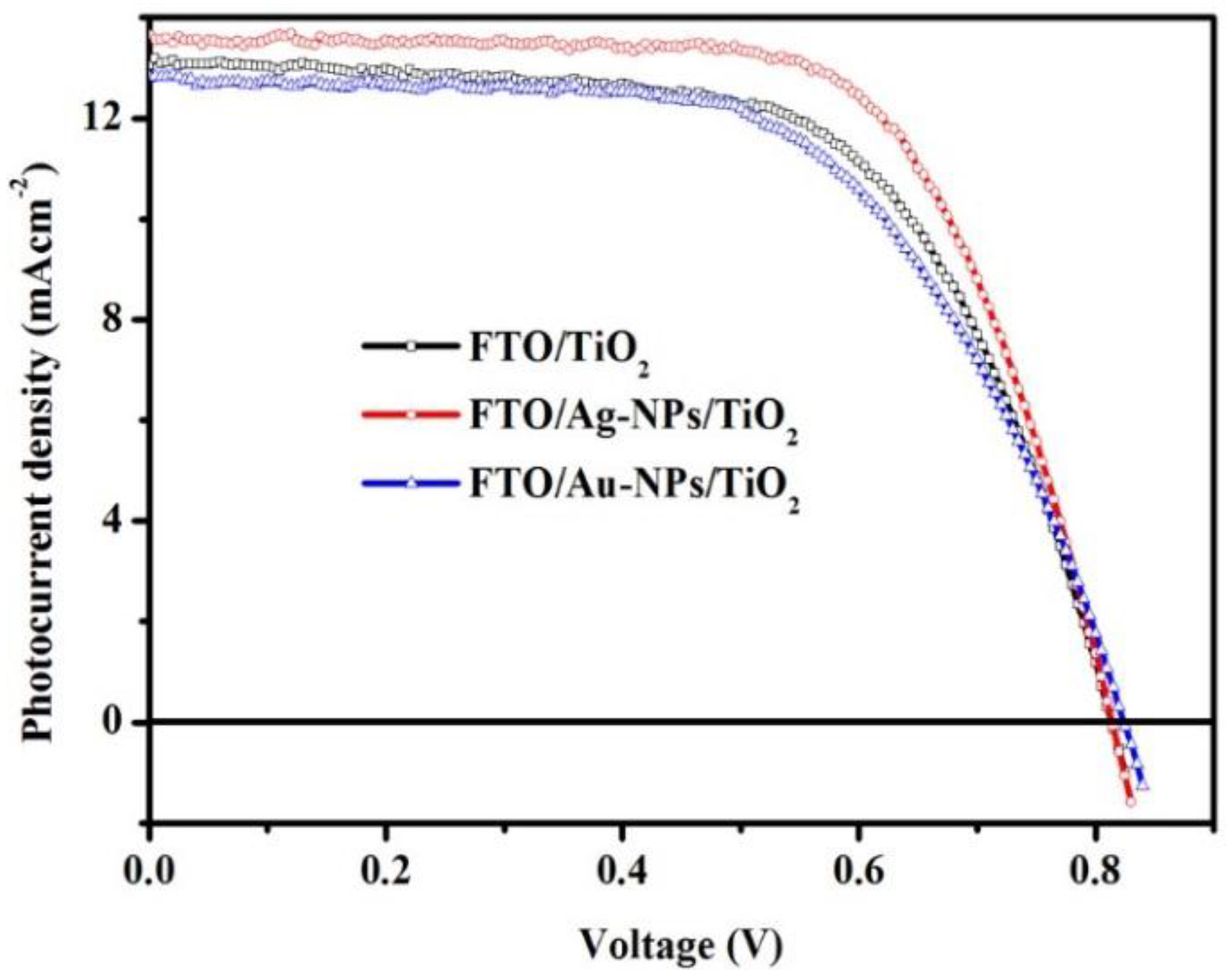
| Working Electrode | Jsc (mA·cm−2) | Voc (mV) | FF (%) | η (%) |
|---|---|---|---|---|
| FTO/TiO2 | 12.83 ± 0.21 | 820.00 ± 5.00 | 61.71 ± 1.16 | 6.54 ± 0.15 |
| FTO/Ag-NPs/TiO2 | 13.49 ± 0.16 | 821.66 ± 11.5 | 67.60 ± 0.68 | 7.49 ± 0.14 |
| FTO/Au-NPs/TiO2 | 12.34 ± 0.67 | 826.67 ± 7.63 | 60.60 ± 1.02 | 6.27 ± 0.11 |
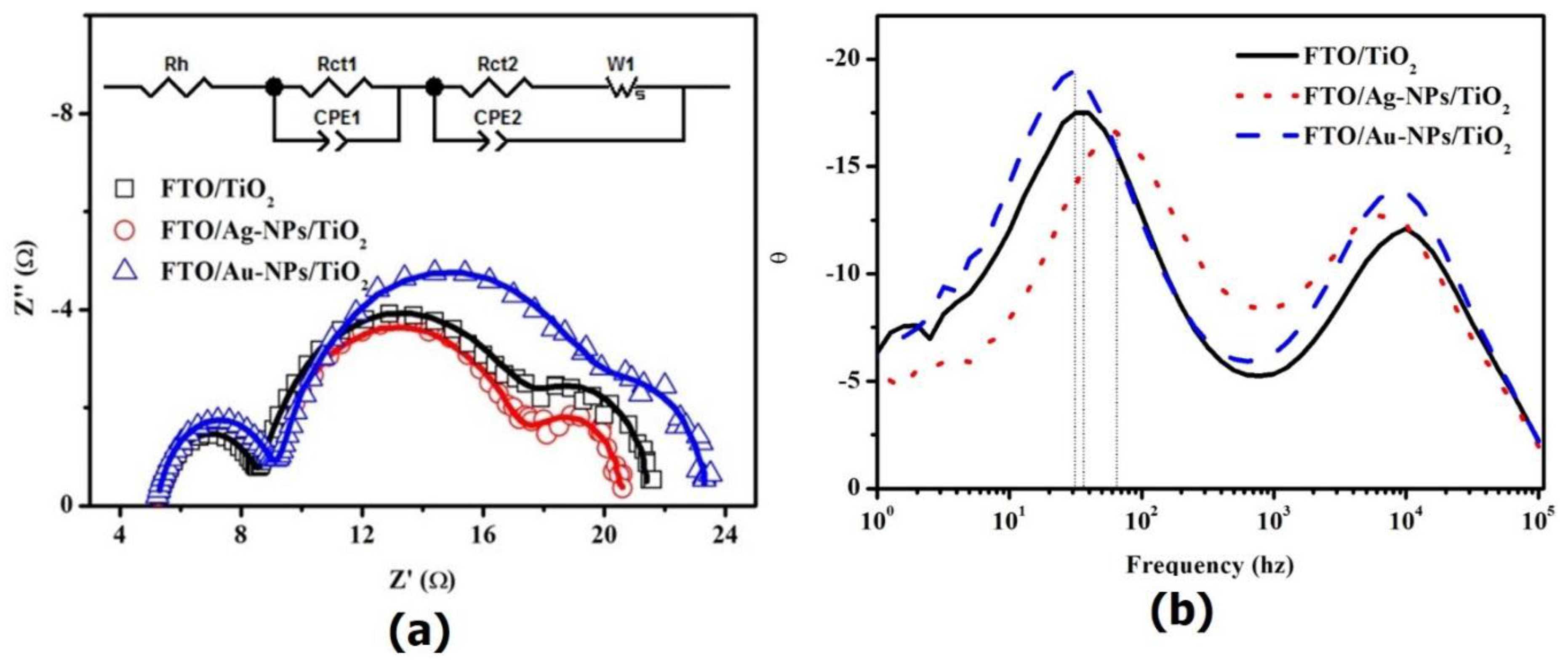
| Working Electrode | Rh (Ω·cm2) | Rct1 (Ω·cm2) | CPE1-T (µF·cm−2) | CPE1-P | Rct2 (Ω·cm2) | Ws | CPE2-T (µF·cm−2) | CPE2-P | ||
|---|---|---|---|---|---|---|---|---|---|---|
| R | T | P | ||||||||
| FTO/TiO2 | 2.59 | 1.81 | 35.5 | 0.90 | 4.24 | 2.08 | 0.42 | 0.5 | 2410 | 0.90 |
| FTO/Ag-NPs/TiO2 | 2.58 | 1.85 | 36.9 | 0.89 | 3.93 | 1.73 | 0.43 | 0.5 | 2470 | 0.90 |
| FTO/Au-NPs/TiO2 | 2.56 | 1.89 | 36.1 | 0.90 | 5.23 | 1.74 | 0.40 | 0.5 | 2450 | 0.90 |
© 2016 by the authors; licensee MDPI, Basel, Switzerland. This article is an open access article distributed under the terms and conditions of the Creative Commons by Attribution (CC-BY) license (http://creativecommons.org/licenses/by/4.0/).
Share and Cite
Dao, V.-D.; Choi, H.-S. Highly-Efficient Plasmon-Enhanced Dye-Sensitized Solar Cells Created by Means of Dry Plasma Reduction. Nanomaterials 2016, 6, 70. https://doi.org/10.3390/nano6040070
Dao V-D, Choi H-S. Highly-Efficient Plasmon-Enhanced Dye-Sensitized Solar Cells Created by Means of Dry Plasma Reduction. Nanomaterials. 2016; 6(4):70. https://doi.org/10.3390/nano6040070
Chicago/Turabian StyleDao, Van-Duong, and Ho-Suk Choi. 2016. "Highly-Efficient Plasmon-Enhanced Dye-Sensitized Solar Cells Created by Means of Dry Plasma Reduction" Nanomaterials 6, no. 4: 70. https://doi.org/10.3390/nano6040070