Enhanced Efficiency in Dye-Sensitized Solar Cells by Electron Transport and Light Scattering on Freestanding TiO2 Nanotube Arrays


1
Department of Bioscience and Biotechnology, Konkuk University, Seoul 143-701, Korea
2
Department of Chemistry, Seoul National University, Seoul 151-747, Korea
*
Author to whom correspondence should be addressed.
Nanomaterials 2017, 7(10), 345; https://doi.org/10.3390/nano7100345
Submission received: 14 September 2017
/
Revised: 18 October 2017
/
Accepted: 19 October 2017
/
Published: 24 October 2017
(This article belongs to the Special Issue New Developments in Nanomaterials for Energy Storage and Conversions)
Abstract
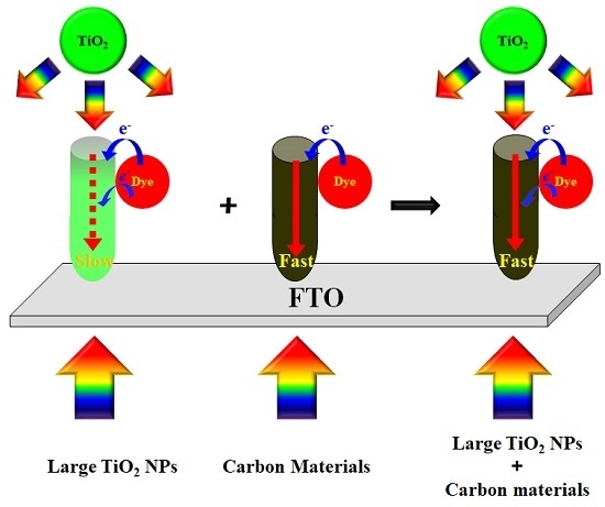
:Dye-sensitized solar cells (DSSCs) were fabricated with closed- or open-ended freestanding TiO2 nanotube arrays as photoelectrodes that were decorated with carbon materials and large TiO2 nanoparticles (NPs) to enhance energy conversion efficiency. The energy conversion efficiency of DSSCs based on open-ended freestanding TiO2 nanotube arrays increased from 4.47% to 5.39%, compared to the DSSCs based on closed-ended freestanding TiO2 nanotube arrays. In DSSCs based on the open-ended freestanding TiO2 nanotube arrays, the energy conversion efficiency with carbon materials increased from 5.39% to 6.19% due to better electron transport, and that with a scattering layer from 5.39% to 6.24% due to more light harvesting compared to the DSSCs without carbon materials or scattering layer. Moreover, the energy conversion efficiency of DSSCs based on the open-ended freestanding TiO2 nanotube arrays with both carbon materials and scattering layer increased from 5.39% to 6.98%, which is an enhancement of 29.50%. In DSSCs based on the TiO2 nanotube arrays, the carbon materials can improve electron transport by π-π conjugation, and the large TiO2 NPs can enhance the capacity to light-harvest by scattering.
1. Introduction
Building-integrated photovoltaics (BIPVs) are one of the essential components in the Smart Grid, and require transparency, flexibility, light weight, low cost, and high power conversion efficiency [1,2]. Since their initial development in 1991 by the Grätzel group [3,4], dye-sensitized solar cells (DSSCs) have been one of the promising BIPV candidates, since their structure is composed of transparent conducting oxide (TCO), an n-type nanostructured semiconductor, a visible-light absorber sensitizer, electrolytes (iodide/triiodide, I−/I3−), and a counter electrode [5]. In addition, eco-friendliness and improvement in stability have become one of the foci in recent research into DSSCs. Liquid-state electrolytes consisting of redox couple and a few additives have been used in conventional DSSCs because of their high energy conversion efficiency [3]. However, to improve the stability of the DSSCs, quasi-solid or solid-state electrolytes would be more favored over the liquid-state electrolytes. For the development of eco-friendly devices, water-based DSSCs (i.e., “aqueous DSSCs”) have attracted attention as they exhibit non-flammable, cost-effective, and eco-friendly properties [1,2,5,6,7,8,9].
Mesoporous TiO2 nanoparticle (NP) films are generally used in the studies of DSSCs, as the films have a desirable direct band gap (3.2 eV) and a large surface area for adsorbing dyes, both of which help to generate electrons [10,11,12,13]. However, the efficiencies of the films might be limited by their grain boundaries, defects, and innumerous trapping sites that can cause charge recombination and low electron mobility from their structures, which are randomly networked [4,14].
TiO2 nanotubes have great potential to overcome the issues of TiO2 NP films, since their unique structure enhances electron transport and charge separation by forging direct pathways and by accelerating charge transfer between interfaces [15,16,17]. TiO2 nanotube arrays can improve energy conversion efficiencies because of their highly-ordered and vertically-oriented tubular structures and because of their innate advantages. The structure of TiO2 nanotube arrays needs to be taken into consideration in order to capitalize on the advantages of TiO2 nanotube arrays. Although DSSCs based on TiO2 nanotube arrays have a great potential for enhancing power conversion efficiency (PCE), DSSCs based on closed-ended TiO2 nanotube arrays—which are the typically employed TiO2 nanotube arrays—exhibited lower energy conversion efficiencies than those of DSSCs based on TiO2 NP films. Recently, we have demonstrated that open-ended TiO2 nanotube arrays in DSSCs, where barrier layers have been removed, exhibited higher PCE [18].
Scattering materials such as TiO2, ZrO2, and SiO2 can improve the energy conversion efficiency by light harvesting. Especially, TiO2 is one of the best materials to use for scattering owing to its high chemical stability and dye adsorption capability. As such, TiO2 scattering materials have been introduced on mesoporous TiO2 NP films for the enhancement of light harvesting [19].
Carbon materials, including carbon nanotubes (CNTs), graphene, or graphite, are promising materials in improving charge separation and electron transport in solar cells due to their enhanced electrical properties by π-π conjugation. The main role of carbon 60 or CNTs in organic solar cells is to function as electron acceptors or charge separators [20]. TiO2 composite films with carbon nanotubes or graphene as photoanodes showed better energy conversion efficiency due to the sp2 structure of the carbon materials [21,22,23,24]. However, it remains a challenging task to directly incorporate those carbon materials into a well-ordered and vertically oriented tubular structure of TiO2 nanotube arrays.
Herein, we show that large TiO2 NPs were introduced onto open- or closed-ended freestanding TiO2 nanotube arrays for more light harvesting, and subsequently carbon materials were synthesized into the well-ordered and vertically oriented tubular structure of TiO2 nanotube arrays for better electron transport. The performances of DSSCs based on the open- or closed-ended freestanding TiO2 nanotube arrays with/without carbon materials and/or large TiO2 NPs were compared to elucidate the influence of each component on the energy conversion efficiency of DSSCs.
2. Results and Discussion
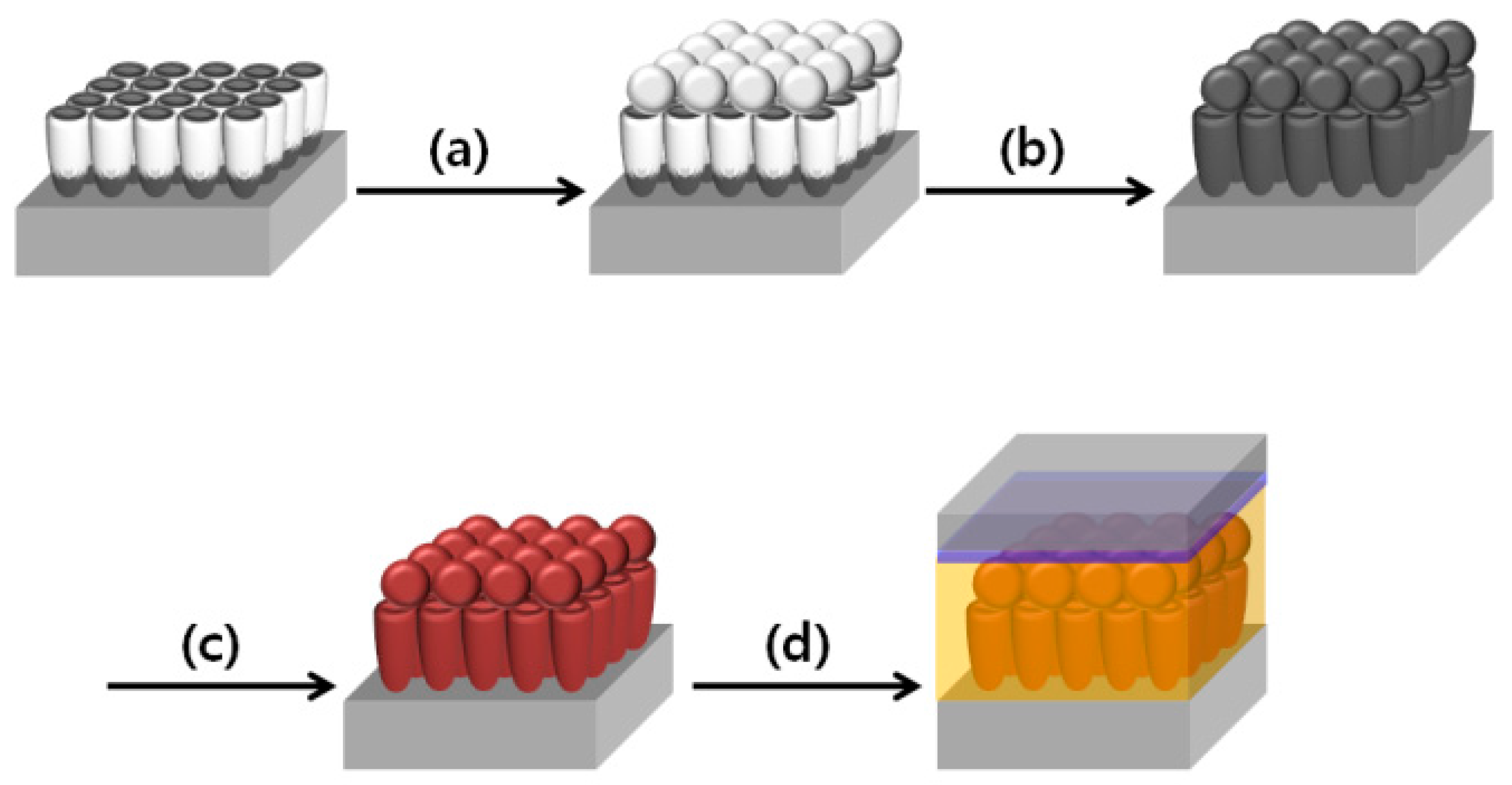
Figure 1 illustrates the fabrication of DSSCs based on closed- or open-ended freestanding TiO2 nanotube arrays with carbon materials and large TiO2 NPs as photoanode. The closed- or open-ended freestanding TiO2 nanotube arrays were prepared by anodization, and their bottom layer was removed by ion milling process. When the bottom layer is present under the freestanding TiO2 nanotube arrays, they are known as “closed-ended” freestanding TiO2 nanotube arrays, whereas without the bottom layer, they are called “open-ended” freestanding TiO2 nanotube arrays. Both types of freestanding TiO2 nanotube arrays were attached on the fluorine-doped tin oxide (FTO) glass, and the large TiO2 NPs (~400 nm) were coated onto both types of freestanding TiO2 nanotube arrays as shown in Figure 1a. The carbon materials were synthesized by the chemical vapor deposition (CVD) method (Figure 1b), and then the dye (N719) was adsorbed onto both types of freestanding TiO2 nanotube array (Figure 1c). Finally, DSSCs were fabricated by assembling the photoanode and counter electrode that were coated with platinum (Pt) on the FTO glass. Electrolyte was injected between the photoanode and counter electrode (Figure 1d).
Figure 2 shows field emission scanning electron microscope (FE-SEM) images of closed- or open-ended freestanding TiO2 nanotube arrays. The top view of the freestanding TiO2 nanotube arrays can been seen in Figure 2a. The pore size was approximately 100 nm after anodization. Figure 2b shows the bottom view of freestanding TiO2 nanotube arrays before the ion milling process. The pattern of the bottom pore size was about 100 nm. Figure 2c shows the bottom view of freestanding TiO2 nanotube arrays after the ion milling process, and the pore size was about 30 nm. The size of the bottom pore was much smaller when compared to the sizes of top pore and the pattern of the bottom pore. However, when the levels of thickness were compared, the bottom wall (~35 nm) was much thicker than the top wall of the freestanding TiO2 nanotube arrays. In previous works [18,25,26,27,28,29,30], we reported that the shape of TiO2 nanotube arrays prepared by anodization were likely to be a corn shape type and that the thicker bottom layer disturbed the electron transport and electrolyte diffusion. Therefore, we suggested that the removal of the bottom layer would facilitate better energy conversion efficiency in DSSCs. Figure 2d shows the side view of freestanding TiO2 nanotube arrays and large TiO2 NPs on the FTO glass. The thickness of the freestanding TiO2 nanotube arrays was approximately 18 μm, and the thickness of large TiO2 NPs was approximately 3 μm.
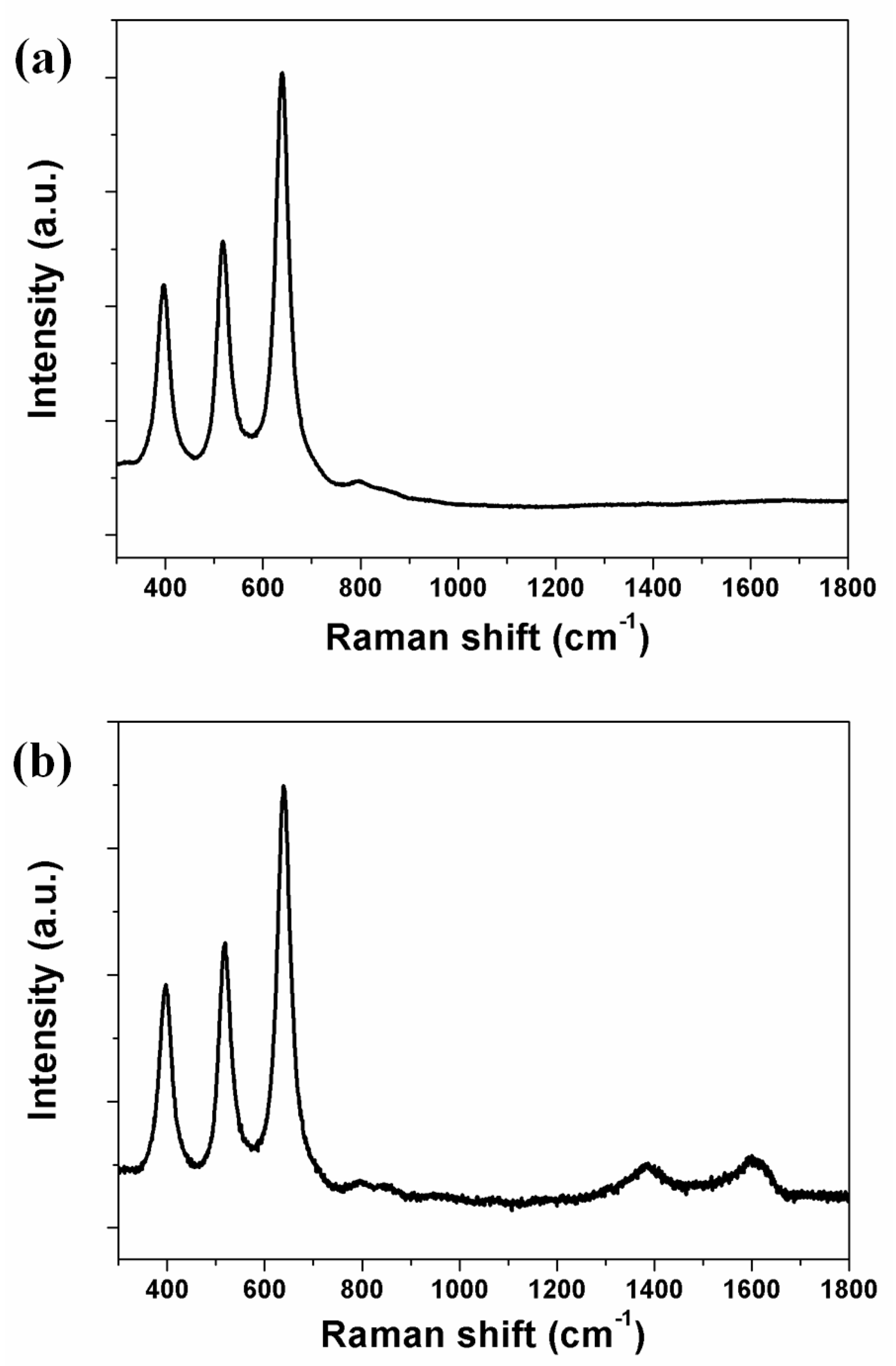
Carbon materials were synthesized on the freestanding TiO2 nanotube arrays by the CVD method, and their structure was confirmed by Raman spectroscopy, as shown in Figure 3. The TiO2 nanotube arrays were confirmed at B1g (395 cm−1), A1g (517 cm−1), and Eg (639 cm−1) peaks, indicating that the form of the TiO2 nanotube arrays was anatase (Figure 3a). Previously, we have attempted to confirm carbon materials using a transmission electron microscopy (TEM), but experienced difficulties in distinguishing the carbon materials that were located on the wall of TiO2 nanotube arrays [30,31]. Using Raman spectroscopy, on the other hand, the carbon materials on the freestanding TiO2 nanotube arrays could be confirmed from the G band at 1600 cm−1, representing graphite, and the D band at 1384 cm−1, representing a disorderly network of sp2 and sp3 sites in the carbon materials (Figure 3b). In the sp2 sites of carbon materials, π-π conjugation had a positive effect on electron transport in enhancing the energy conversion efficiency of DSSCs.
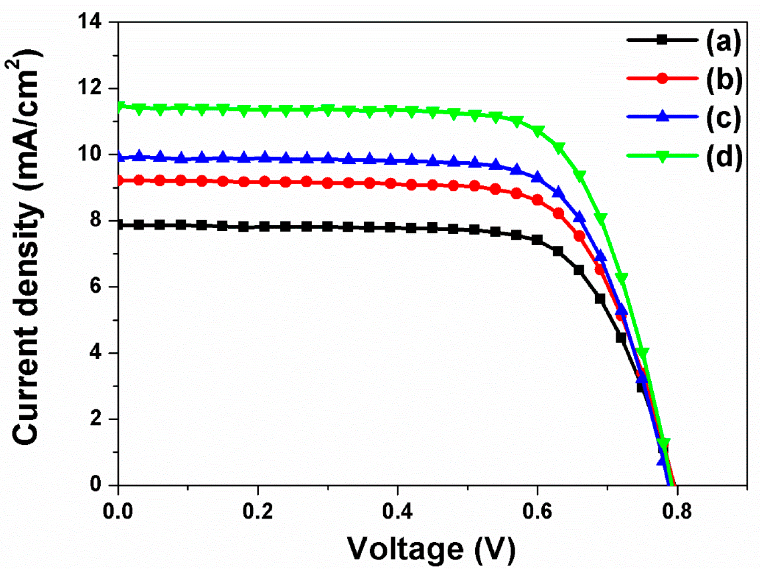
The current density-voltage curves (I-V) of DSSCs based on closed-ended TiO2 nanotube arrays with/without carbon materials and/or large TiO2 NPs were measured under air-mass (AM) 1.5 sunlight. The results are presented in Figure 4. The open circuit voltage (Voc), short-circuit current density (Jsc), fill factor (ff), and energy conversion efficiency (η) of DSSCs are summarized in Table 1. In DSSCs based on closed-ended TiO2 nanotube arrays without carbon materials and large TiO2 NPs, the energy conversion efficiency was 4.47%. In DSSCs based on closed-ended TiO2 nanotube arrays with carbon materials or with large TiO2 NPs, the energy conversion efficiency values were 5.24% and 5.63%, respectively. Although DSSCs based on closed-ended TiO2 nanotube arrays with carbon materials had lower dye loading (from 138 nmol/cm2 to 124 nmol/cm2), as dye could not be adsorbed onto the carbon materials, the energy conversion efficiency values were higher than that of DSSCs without carbon materials and large TiO2 NPs. Nevertheless, electron transport would be improved by carbon materials, which can enhance the energy conversion efficiency of DSSCs. In DSSCs with large TiO2 NPs, their energy conversion efficiency was higher than that of DSSCs without carbon materials and large TiO2 NPs. In this case, their light harvesting would also be improved by large TiO2 NPs, which are favorable in enhancing the energy conversion efficiency. Additionally, the DSSCs based on closed-ended TiO2 nanotube arrays with carbon materials and large TiO2 NPs showed increased energy conversion efficiency from 4.47% to 6.52%, corresponding to a 45.86% enhancement. The results can be attributed to their improved electron transport and light harvesting by π-π conjugation and scattering layer. These results suggest that the increase in energy conversion efficiency of DSSCs depends on the improved ability of electron transport and light harvesting by carbon materials and large TiO2 NPs.
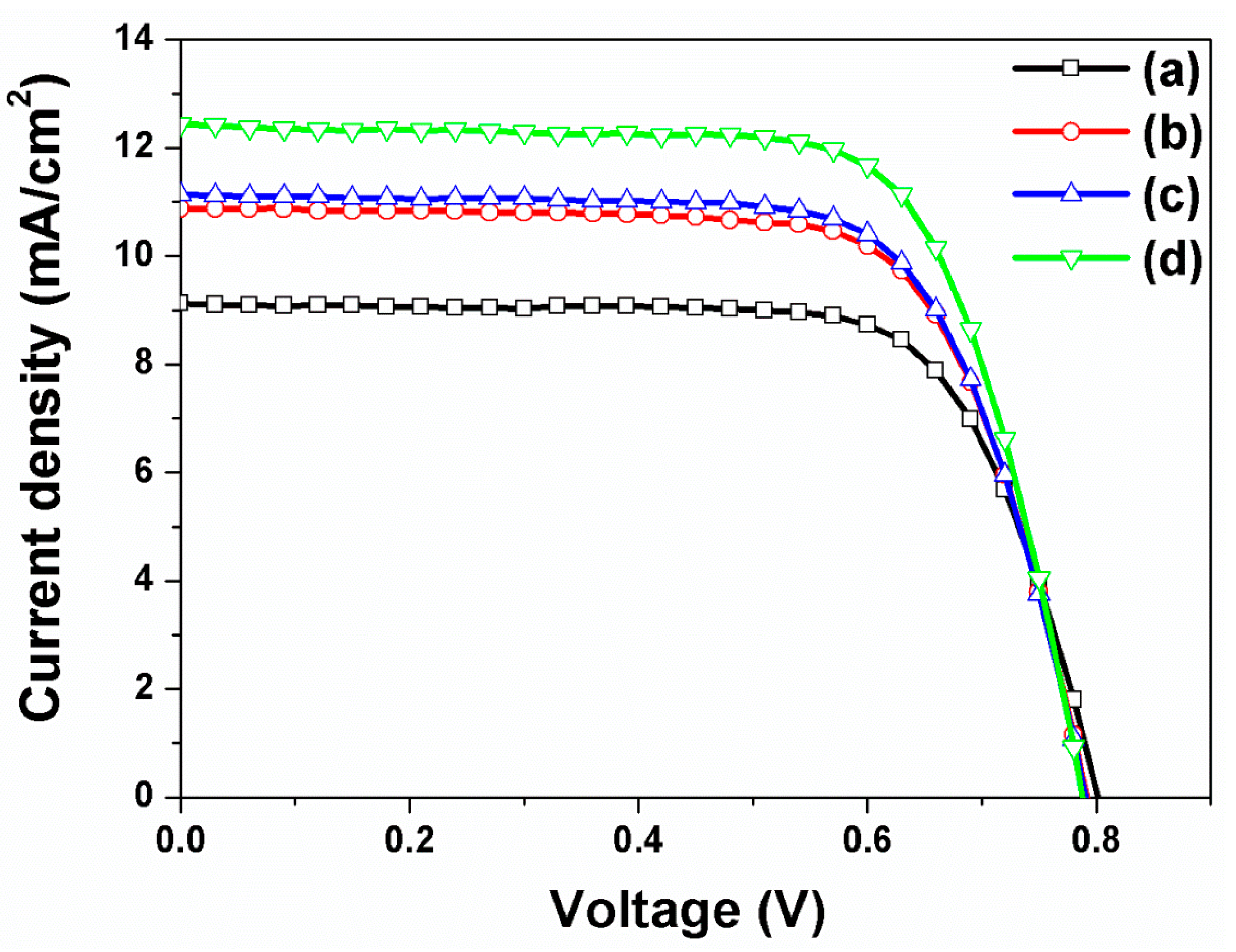
The current density-voltage curves of DSSCs based on open-ended TiO2 nanotube arrays with/without carbon materials were also measured under AM 1.5 sunlight, and the results are presented in Figure 5. The values of Voc, Jsc, ff, and η of DSSCs are summarized in Table 2. In general, the energy conversion efficiencies of DSSCs based on the open-ended TiO2 nanotube arrays were higher than those based on the closed-ended TiO2 nanotube arrays. Our previous work demonstrated that the electron transfer and electrolyte diffusion of DSSCs based on open-ended TiO2 nanotube arrays were better than that based on closed-ended TiO2 nanotube arrays [18]. The energy conversion efficiency of DSSCs based on open-ended TiO2 nanotube arrays increased from 4.47% to 5.39%. When the carbon materials were decorated on the TiO2 nanotube arrays, the energy conversion efficiency of DSSCs based on the open-ended TiO2 nanotube arrays increased from 5.39% to 6.19% (14.84% enhancement), which is due to better electron transport by π-π conjugation. When the large TiO2 NPs were introduced onto the open-ended TiO2 nanotube arrays, the energy conversion efficiency of DSSCs increased from 5.39% to 6.24% (15.77% enhancement), due to more light harvesting by the scattering layer. To capitalize on the synergetic effects between carbon materials and large TiO2 NPs in improving energy conversion efficiency, the DSSCs based on open-ended TiO2 nanotube arrays were fabricated with carbon materials and large TiO2 NPs. The energy conversion efficiency increased from 5.39% to 6.98% (29.50% enhancement). It can be suggested that greater electron transport was facilitated by carbon materials and the better light harvesting by large TiO2 NPs, both of which simultaneously improved the energy conversion efficiency of DSSCs. Moreover, the results showed that the energy conversion efficiencies of DSSCs based on open-ended TiO2 nanotube arrays were mostly greater than those based on closed-ended TiO2 nanotube arrays.
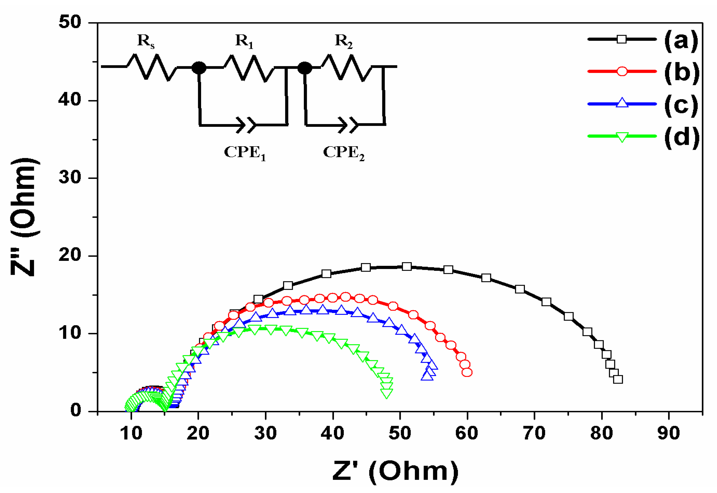
The DSSCs based on the open-ended TiO2 nanotube array were characterized by electrical impedance spectroscopy (EIS) across the frequency range from 10−2 Hz to 106 Hz (as shown in Figure 6), and the fit parameters are listed in Table 3. The applied bias voltage was set at the Voc with an AC amplitude of 10 mV. The ohmic series resistance (Rs) is a sheet resistance corresponding to the x-axis value where a first semicircle begins, as can been seen on the left of Figure 6. When the Rs value in DSSCs based on the open-ended TiO2 nanotube arrays is compared, it was similar to that with/without carbon materials and/or large TiO2 NPs. The result indicates that the resistance of the sheet against the FTO or the current collector is not affected by the carbon materials and large TiO2 NPs. The R1 value is the sum of the small semicircles at the high frequency. The value was assigned to the parallel combination of resistances and the capacitances at the Pt-FTO/electrolyte and the FTO/TiO2 interfaces. The R1 value of DSSCs without carbon materials and large TiO2 NPs was 6.16 Ω, and the R1 value of DSSCs with carbon materials or large TiO2 NPs was 6.23 Ω and 5.91 Ω, respectively. When DSSCs were fabricated with carbon materials and large TiO2 NPs, the R1 value became 5.11 Ω, which was much lower than without carbon materials and large TiO2 NPs. The results indicate that a greater amount of electrons were generated by the large TiO2 NPs, and that electrons were transferred between the FTO and the TiO2. The R2 value is given by the sum of the large semicircles at low frequency, which is also associated with the resistance and the capacitance at the dye-adsorbed TiO2/electrolyte interface and the transport resistance. The R2 value of DSSCs without carbon materials and large TiO2 NPs was 56.27 Ω. When carbon materials were decorated on the TiO2 nanotube arrays, the R2 value decreased to 37.43 Ω, as transport resistance decreased by π-π conjugation. The R2 value of DSSCs with large TiO2 NPs decreased to 34.26 Ω, due to greater electrons being generated by scattering at the dye-adsorbed TiO2/electrolyte interface. In DSSCs based on the open-ended TiO2 nanotube arrays with carbon materials and large TiO2 NPs, the value of R2 decreased to 29.02 Ω due to the synergistic effect by π-π conjugation and by scattering layer, affecting the FTO/TiO2 and TiO2/electrolyte interfaces.
3. Materials and Methods
3.1. Materials
Titanium (Ti) plate (99.7% purity, 0.25 mm thickness), ammonium fluoride (NH4F, 97.0%), ethylene glycol (99%), hydrogen peroxide (30%), FTO glass, titanium diisopropoxide bis(acetylacetonate) solution (75 wt. % in isopropanol), n-butanol, TiO2 paste, scattering TiO2 paste, titanium chloride (TiCl4), dye cis-diisothiocyanato-bis(2,2′-bipyridyl-4,4′-dicarboxylato) ruthenium(II) bis(tetrabutylammonium), N719, chloroplatinic acid hexahydrate (H2PtCl6·6H2O), 1-butyl-3-methyl-imidazolium iodide (BMII), iodine (I2), guanidium thiocyanate (GSCN), 4-tertbutylpyridine (TBP), acetonitrile (CH3CN), and valeronitrile (CH3(CH2)3CN) were purchased from Alfa Aesar (Haverhill, MA, USA), Showa Chemical Co., (Beijing, China), Daejung Chemical (Shiheung-City, Korea), Pilkington (St. Helens, UK), Aldrich (St. Louis, MO, USA), Solaronix (Aubonne, Switzerland), and Dyesol (Queanbeyan, Australia).
3.2. Preparation of Closed- or Open-Ended Freestanding TiO2 Nanotube Arrays
TiO2 nanotube arrays were prepared by anodization from a Ti plate that was carried out in an electrolyte composed of 0.8 wt. % NH4F and 2 vol. % H2O in ethylene glycol. The constant voltage was 60 V DC at 25 °C for 2 h. After the anodization, the Ti plate was annealed at 500 °C for 30 min under ambient conditions to improve the crystallinity of TiO2 nanotube arrays. To detach the TiO2 nanotube arrays from the Ti plate, a secondary anodization was carried out at a constant voltage of 30 V DC for 10 min and then the Ti plate was immersed in 10% H2O2 solution for several hours, the results of which are called closed-ended freestanding TiO2 nanotube arrays. To prepare open-ended freestanding TiO2 nanotube arrays, the bottom of the freestanding TiO2 nanotube arrays was removed by ion milling with Ar+ bombardment for several minutes.
3.3. Fabrication of DSSCs with Closed- or Open-Ended Freestanding TiO2 Nanotube Arrays with Scattering Layer
The TiO2 paste was coated on the FTO glass, and the closed- or open-ended freestanding TiO2 nanotube arrays were put on the substrates and then sintered at 500 °C for 1 h under ambient conditions to induce crystallinity and adhesion between the TiO2 NPs and freestanding TiO2 nanotube arrays. After an annealing step, the ~400 nm TiO2 NPs were coated on the freestanding TiO2 nanotube arrays for a scattering layer and sintered at 500 °C for 1 h under ambient conditions for their crystallinity. To increase the dye adsorption, the substrates were treated with 0.01 M TiCl4 solution for 30 min and sintered at 500 °C for 1 h under ambient conditions for their crystallinity. The substrates were immersed in a dye solution at 50 °C for 8 h, which were then called working electrodes. The working electrodes were sandwiched with a counter electrode that was coated with Pt on the FTO glass by using a 60-μm-thick hot-melt sheet. The electrolyte was filled between the working and the counter electrode. The electrolyte was comprised of 0.7 M 1-butyl-3-methyl-imidazolium iodide (BMII), 0.03 M I2, 0.1 M guanidium thiocyanate (GSCN), and 0.5 M 4-tertbutylpyridine (TBP) in a mixture of acetonitrile and valeronitrile (85:15, v/v).
3.4. Instruments
The morphology, thickness, size, and structure of freestanding TiO2 nanotube arrays were confirmed using a FE-SEM (JSM-6330F, JEOL Inc., Tokyo, Japan). The current density-voltage (J-V) characteristics and the incident photon-to-current conversion efficiency (IPCE) of the DSSCs were measured using an electrometer (Keithley 2400, Keithley Instruments, Inc., Cleveland, OH, USA) under AM 1.5 illumination (100 mW/cm2) provided by a solar simulator (1 KW xenon with AM 1.5 filter) or using a McScience (model K3100, McScience Inc., Suwon, Korea) with reference to a calibrated diode.
4. Conclusions
We prepared DSSCs based on closed- or open-ended TiO2 nanotube arrays as photoanodes that contained the carbon materials and large TiO2 NPs to improve energy conversion efficiency. The energy conversion efficiency of DSSCs based on the closed- or open-ended TiO2 nanotube arrays with carbon materials had higher energy conversion efficiency than that of DSSCs without carbon materials. This was due to the carbon materials being composed of π-π conjugation on their structure, which is more conducive to electron transports. The energy conversion efficiency of DSSCs based on the closed- or open-ended TiO2 nanotube arrays with large TiO2 NPs showed greater energy conversion efficiency than that of DSSCs without large TiO2 NPs, as large TiO2 NPs could generate more electrons by light harvesting. Moreover, the energy conversion efficiency of DSSCs based on the closed- or open-ended TiO2 nanotube arrays with carbon materials and with large TiO2 NPs showed much higher energy conversion efficiency than that of DSSCs without carbon materials and large TiO2 NPs due to their combined effects of enhanced electron transports and electron generation. Our results suggest that the carbon materials and large TiO2 NPs could be applied to organic solar cells (e.g., hybrid or perovskite solar cells) to improve their energy conversion efficiency.
Supplementary Materials
The following are available online at https://www.mdpi.com/2079-4991/7/10/345/s1.
Acknowledgments
This work was supported by the Bio & Medical Technology Development Program of the National Research Foundation (NRF) and funded by the Korean government (MSIP & MOHW) (2016M3A9B6918892).
Author Contributions
Rho, W.-Y. conceived and designed the experiments; Song, D.H. performed the experiments; Song, D.H. and Lee, S.H. analyzed the data; Jun, B.-H., Song, D.H., and Rho, W.-Y. wrote the paper.
Conflicts of Interest
The authors declare no conflict of interest. The founding sponsors had no role in the design of the study; in the collection, analyses, or interpretation of data; in the writing of the manuscript, and in the decision to publish the results.
References
- Bella, F.; Lamberti, A.; Bianco, S.; Tresso, E.; Gerbaldi, C.; Pirri, C.F. Floating Flexible Polymeric Dye-Sensitized Solar-Cell Architecture: The Way of Near-Future Photovoltaics. Adv. Mater. Technol. 2016, 1, 1600002. [Google Scholar] [CrossRef]
- Galliano, S.; Bella, F.; Gerbaldi, C.; Falco, M.; Viscardi, G.; Grätzel, M.; Barolo, C. Photoanode/Electrolyte Interface Stability in Aqueous Dye-Sensitized Solar Cells. Energy Technol. 2017, 5, 300–311. [Google Scholar] [CrossRef]
- Oregan, B.; Gratzel, M. A Low-Cost, High-Efficiency Solar-Cell Based on Dye-Sensitized Colloidal TiO2 Films. Nature 1991, 353, 737–740. [Google Scholar] [CrossRef]
- Gratzel, M. Photoelectrochemical cells. Nature 2001, 414, 338–344. [Google Scholar] [CrossRef] [PubMed]
- Bella, F.; Gerbaldi, C.; Barolo, C.; Grätzel, M. Aqueous dye-sensitized solar cells. Chem. Soc. Rev. 2015, 44, 3431–3473. [Google Scholar] [CrossRef] [PubMed]
- Bella, F.; Pugliese, D.; Zolin, L.; Gerbaldi, C. Paper-based quasi-solid dye-sensitized solar cells. Electrochim. Acta 2017, 237, 87–93. [Google Scholar] [CrossRef]
- Shanti, R.; Bella, F.; Salim, Y.; Chee, S.; Ramesh, S.; Ramesh, K. Poly (methyl methacrylate-co-butyl acrylate-co-acrylic acid): Physico-chemical characterization and targeted dye sensitized solar cell application. Mater. Des. 2016, 108, 560–569. [Google Scholar] [CrossRef]
- Scalia, A.; Bella, F.; Lamberti, A.; Bianco, S.; Gerbaldi, C.; Tresso, E.; Pirri, C.F. A flexible and portable powerpack by solid-state supercapacitor and dye-sensitized solar cell integration. J. Power Sources 2017, 359, 311–321. [Google Scholar] [CrossRef]
- Bella, F.; Verna, A.; Gerbaldi, C. Patterning dye-sensitized solar cell photoanodes through a polymeric approach: A perspective. Mater. Sci. Semicond. Process. 2017. [Google Scholar] [CrossRef]
- Nazeeruddin, M.K.; Pechy, P.; Renouard, T.; Zakeeruddin, S.M.; Humphry-Baker, R.; Comte, P.; Liska, P.; Cevey, L.; Costa, E.; Shklover, V.; et al. Engineering of efficient panchromatic sensitizers for nanocrystalline TiO2-based solar cells. J. Am. Chem. Soc. 2001, 123, 1613–1624. [Google Scholar] [CrossRef] [PubMed]
- Hara, K.; Sato, T.; Katoh, R.; Furube, A.; Ohga, Y.; Shinpo, A.; Suga, S.; Sayama, K.; Sugihara, H.; Arakawa, H. Molecular design of coumarin dyes for efficient dye-sensitized solar cells. J. Phys. Chem. B 2003, 107, 597–606. [Google Scholar] [CrossRef]
- Galoppini, E. Linkers for anchoring sensitizers to semiconductor nanoparticles. Coord. Chem. Rev. 2004, 248, 1283–1297. [Google Scholar] [CrossRef]
- Sang, L.; Zhao, Y.; Burda, C. TiO2 nanoparticles as functional building blocks. Chem. Rev. 2014, 114, 9283–9318. [Google Scholar] [CrossRef] [PubMed]
- Du, L.; Furube, A.; Yamamoto, K.; Hara, K.; Katoh, R.; Tachiya, M. Plasmon-induced charge separation and recombination dynamics in gold-TiO2 nanoparticle systems: Dependence on TiO2 particle size. J. Phys. Chem. C 2009, 113, 6454–6462. [Google Scholar] [CrossRef]
- Mor, G.K.; Varghese, O.K.; Paulose, M.; Shankar, K.; Grimes, C.A. A review on highly ordered, vertically oriented TiO2 nanotube arrays: Fabrication, material properties, and solar energy applications. Sol. Energy Mater. Sol. Cells 2006, 90, 2011–2075. [Google Scholar] [CrossRef]
- Shin, Y.; Lee, S. Self-organized regular arrays of anodic TiO2 nanotubes. Nano Lett. 2008, 8, 3171–3173. [Google Scholar] [CrossRef] [PubMed]
- Rho, W.-Y.; Jeon, H.; Kim, H.-S.; Chung, W.-J.; Suh, J.S.; Jun, B.-H. Recent Progress in Dye-Sensitized Solar Cells for Improving Efficiency: TiO2 Nanotube Arrays in Active Layer. J. Nanomater. 2015, 2015, 1–17. [Google Scholar] [CrossRef]
- Rho, C.; Min, J.-H.; Suh, J.S. Barrier layer effect on the electron transport of the dye-sensitized solar cells based on TiO2 nanotube arrays. J. Phys. Chem. C 2012, 116, 7213–7218. [Google Scholar] [CrossRef]
- Katoh, R.; Furube, A.; Yoshihara, T.; Hara, K.; Fujihashi, G.; Takano, S.; Murata, S.; Arakawa, H.; Tachiya, M. Efficiencies of electron injection from excited N3 dye into nanocrystalline semiconductor (ZrO2, TiO2, ZnO, Nb2O5, SnO2, In2O3) films. J. Phys. Chem. B 2004, 108, 4818–4822. [Google Scholar] [CrossRef]
- Pradhan, B.; Batabyal, S.K.; Pal, A.J. Functionalized carbon nanotubes in donor/acceptor-type photovoltaic devices. Appl. Phys. Lett. 2006, 88, 3106. [Google Scholar] [CrossRef]
- Zhang, H.; Lv, X.; Li, Y.; Wang, Y.; Li, J. P25-graphene composite as a high performance photocatalyst. ACS Nano 2010, 4, 380–386. [Google Scholar] [CrossRef] [PubMed]
- Yadav, S.K.; Madeshwaran, S.R.; Cho, J.W. Synthesis of a hybrid assembly composed of titanium dioxide nanoparticles and thin multi-walled carbon nanotubes using “click chemistry”. J. Colloid Interface Sci. 2011, 358, 471–476. [Google Scholar] [CrossRef] [PubMed]
- Nath, N.C.D.; Sarker, S.; Ahammad, A.S.; Lee, J.-J. Spatial arrangement of carbon nanotubes in TiO2 photoelectrodes to enhance the efficiency of dye-sensitized solar cells. Phys. Chem. Chem. Phys. 2012, 14, 4333–4338. [Google Scholar] [CrossRef] [PubMed]
- Roy-Mayhew, J.D.; Aksay, I.A. Graphene materials and their use in dye-sensitized solar cells. Chem. Rev. 2014, 114, 6323–6348. [Google Scholar] [CrossRef] [PubMed]
- Rho, C.; Suh, J.S. Filling TiO2 nanoparticles in the channels of TiO2 nanotube membranes to enhance the efficiency of dye-sensitized solar cells. Chem. Phys. Lett. 2011, 513, 108–111. [Google Scholar] [CrossRef]
- Rho, W.-Y.; Chun, M.-H.; Kim, H.-D.; Hahn, Y.-B.; Suh, J.S.; Jun, B.-H. Improved energy conversion efficiency of dye-sensitized solar cells fabricated using open-ended TiO2 nanotube arrays with scattering layer. Bull. Korean Chem. Soc. 2014, 35, 1165–1168. [Google Scholar] [CrossRef]
- Rho, W.-Y.; Kim, H.-S.; Lee, S.H.; Jung, S.; Suh, J.S.; Hahn, Y.-B.; Jun, B.-H. Front-illuminated dye-sensitized solar cells with Ag nanoparticle-functionalized freestanding TiO2 nanotube arrays. Chem. Phys. Lett. 2014, 614, 78–81. [Google Scholar] [CrossRef]
- Rho, W.-Y.; Chun, M.-H.; Kim, H.-S.; Kim, H.-M.; Suh, J.S.; Jun, B.-H. Ag Nanoparticle—Functionalized Open-Ended Freestanding TiO2 Nanotube Arrays with a Scattering Layer for Improved Energy Conversion Efficiency in Dye-Sensitized Solar Cells. Nanomaterials 2016, 6, 117. [Google Scholar] [CrossRef] [PubMed]
- Rho, W.-Y.; Kim, H.-S.; Chung, W.-J.; Suh, J.S.; Jun, B.-H.; Hahn, Y.-B. Enhancement of power conversion efficiency with TiO2 nanoparticles/nanotubes-silver nanoparticles composites in dye-sensitized solar cells. Appl. Surf. Sci. 2018. [Google Scholar] [CrossRef]
- Rho, W.-Y.; Kim, H.-S.; Kim, H.-M.; Suh, J.S.; Jun, B.-H. Carbon-doped freestanding TiO2 nanotube arrays in dye-sensitized solar cells. New J. Chem. 2017, 41, 285–289. [Google Scholar] [CrossRef]
- Kim, H.-S.; Chun, M.-H.; Suh, J.S.; Jun, B.-H.; Rho, W.-Y. Dual Functionalized Freestanding TiO2 Nanotube Arrays Coated with Ag Nanoparticles and Carbon Materials for Dye-Sensitized Solar Cells. Appl. Sci. 2017, 7, 576. [Google Scholar] [CrossRef]
Figure 1.
Overall scheme of fabrication of dye-sensitized solar cells (DSSCs) based on closed- or open-ended freestanding TiO2 nanotube arrays decorated with large TiO2 nanoparticles (NPs) and carbon materials. (a) Coating of large TiO2 NPs; (b) Synthesis of carbon materials by chemical vapor deposition (CVD) method; (c) Dye adsorption; and (d) Fabrication of the DSSCs.

Figure 2.
Field emission scanning electron microscope (FE-SEM) images of freestanding TiO2 nanotube arrays. (a) Top view; (b) Bottom view before ion milling process; (c) Bottom view after ion milling process of freestanding TiO2 nanotube arrays; and (d) Side view of freestanding TiO2 nanotube arrays and large TiO2 NPs on the fluorine-doped tin oxide (FTO) glass.
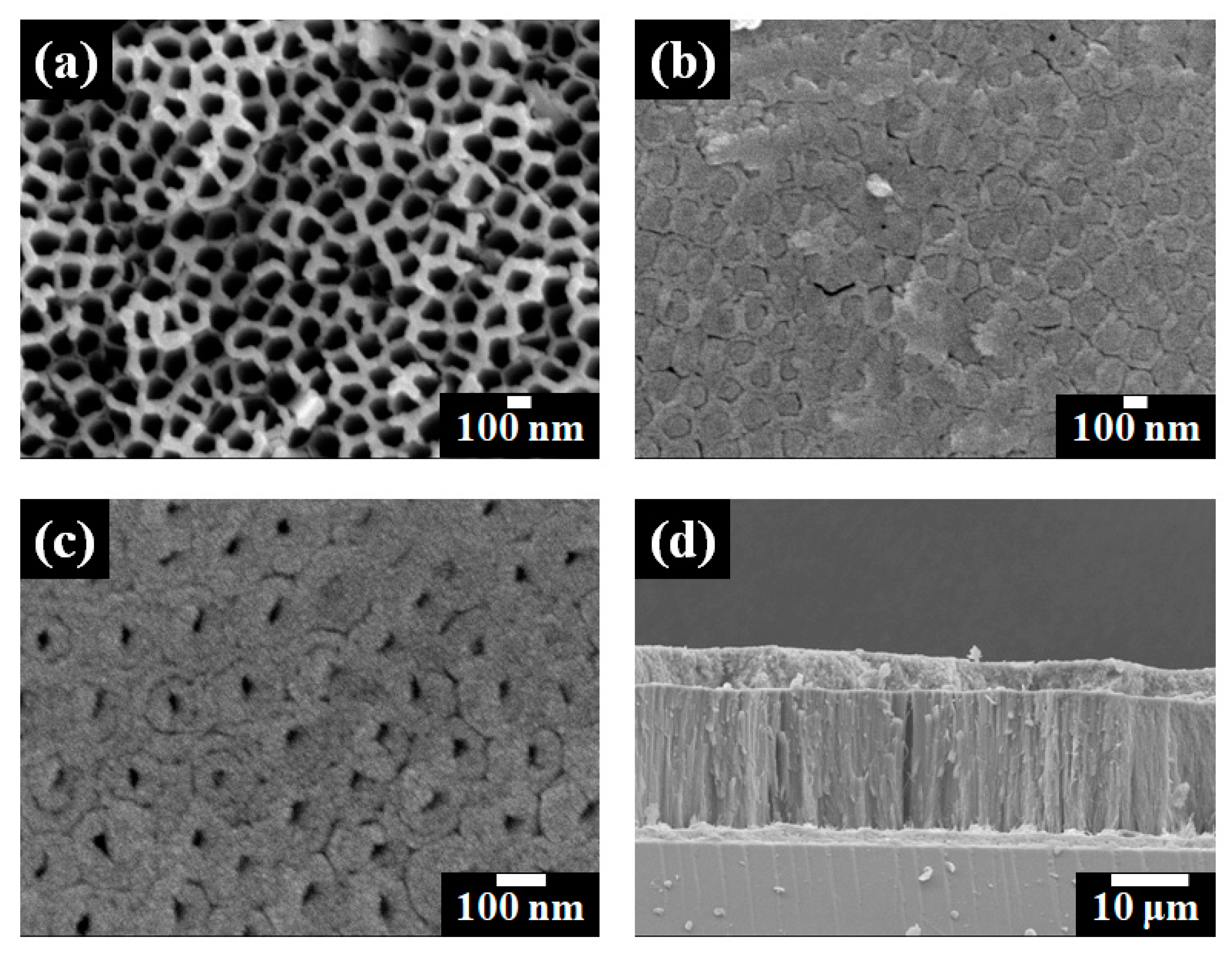
Figure 3.
Raman spectra of (a) freestanding TiO2 nanotube arrays alone and (b) freestanding TiO2 nanotube arrays with carbon materials.
Figure 3.
Raman spectra of (a) freestanding TiO2 nanotube arrays alone and (b) freestanding TiO2 nanotube arrays with carbon materials.

Figure 4.
Current density-voltage (I-V) curves of DSSCs based on closed-ended freestanding TiO2 nanotube arrays: (a) Without carbon materials and large TiO2 NPs; (b) With carbon materials; (c) With large TiO2 NPs; and (d) With carbon materials and large TiO2 NPs.
Figure 4.
Current density-voltage (I-V) curves of DSSCs based on closed-ended freestanding TiO2 nanotube arrays: (a) Without carbon materials and large TiO2 NPs; (b) With carbon materials; (c) With large TiO2 NPs; and (d) With carbon materials and large TiO2 NPs.

Figure 5.
I-V curves of DSSCs based on open-ended freestanding TiO2 nanotube arrays: (a) Without carbon materials and large TiO2 NPs; (b) With carbon materials; (c) With large TiO2 NPs; and (d) With carbon materials and large TiO2 NPs.
Figure 5.
I-V curves of DSSCs based on open-ended freestanding TiO2 nanotube arrays: (a) Without carbon materials and large TiO2 NPs; (b) With carbon materials; (c) With large TiO2 NPs; and (d) With carbon materials and large TiO2 NPs.

Figure 6.
Impedance of DSSCs based on open-ended freestanding TiO2 nanotube arrays: (a) Without carbon materials and large TiO2 NPs; (b) With carbon materials; (c) With large TiO2 NPs; and (d) With carbon materials and large TiO2 NPs.
Figure 6.
Impedance of DSSCs based on open-ended freestanding TiO2 nanotube arrays: (a) Without carbon materials and large TiO2 NPs; (b) With carbon materials; (c) With large TiO2 NPs; and (d) With carbon materials and large TiO2 NPs.


Table 1.
Photovoltaic properties of DSSCs based on closed-ended freestanding TiO2 nanotube arrays with/without carbon materials and with/without large TiO2 NPs.
Table 1.
Photovoltaic properties of DSSCs based on closed-ended freestanding TiO2 nanotube arrays with/without carbon materials and with/without large TiO2 NPs.
| Based on Closed-Ended Freestanding TiO2 Nanotube Arrays | Jsc (mA/cm2) | Voc (V) | ff | η (%) | Dye Loading (nmol/cm2) |
|---|---|---|---|---|---|
| Without carbon materials and large TiO2 NPs | 7.87 | 0.80 | 0.71 | 4.47 | 138 |
| With carbon materials | 9.22 | 0.80 | 0.71 | 5.24 | 124 |
| With large TiO2 NPs | 9.90 | 0.79 | 0.72 | 5.63 | 149 |
| With carbon materials and large TiO2 NPs | 11.47 | 0.79 | 0.72 | 6.52 | 131 |
Note: Jsc: short-circuit current density; Voc: open circuit voltage; ff: fill factor; η: energy conversion efficiency.
Table 2.
Photovoltaic properties of DSSCs based on open-ended freestanding TiO2 nanotube arrays with/without carbon materials and with/without large TiO2 NPs.
Table 2.
Photovoltaic properties of DSSCs based on open-ended freestanding TiO2 nanotube arrays with/without carbon materials and with/without large TiO2 NPs.
| Based on Open-Ended Freestanding TiO2 Nanotube Arrays | Jsc (mA/cm2) | Voc (V) | ff | η (%) | Dye Loading (nmol/cm2) |
|---|---|---|---|---|---|
| Without carbon materials and large TiO2 NPs | 9.12 | 0.81 | 0.73 | 5.39 | 150 |
| With carbon materials | 10.88 | 0.79 | 0.72 | 6.19 | 136 |
| With large TiO2 NPs | 11.14 | 0.79 | 0.71 | 6.24 | 158 |
| With carbon materials and large TiO2 NPs | 12.44 | 0.79 | 0.71 | 6.98 | 141 |
Note: Jsc: short-circuit current density; Voc: open circuit voltage; ff: fill factor; η: energy conversion efficiency.
Table 3.
Parameters of impedance spectra of DSSCs based on open-ended freestanding TiO2 nanotube arrays with/without carbon materials and with/without large TiO2 NPs.
Table 3.
Parameters of impedance spectra of DSSCs based on open-ended freestanding TiO2 nanotube arrays with/without carbon materials and with/without large TiO2 NPs.
| Based on Open-Ended Freestanding TiO2 Nanotube Arrays | Rs (Ω) | R1 (Ω) | CPE1 (F) | R2 (Ω) | CPE2 (F) |
|---|---|---|---|---|---|
| Without carbon materials and large TiO2 NPs | 10.67 | 6.16 | 7.59 × 10⁻⁶ | 56.27 | 1.99 × 10⁻³ |
| With carbon materials | 10.43 | 6.23 | 8.89 × 10⁻⁶ | 37.43 | 1.94 × 10⁻³ |
| With large TiO2 NPs | 10.40 | 5.91 | 7.91 × 10⁻⁶ | 34.26 | 2.21 × 10⁻³ |
| With carbon materials and large TiO2 NPs | 10.26 | 5.11 | 9.86 × 10⁻⁶ | 29.02 | 2.51 × 10⁻³ |
Note: Rs: ohmic series resistance; R1: sum of small semicircles at high frequency; CPE1: constant phase element 1; R2: sum of large semicircles at low frequency; CPE2: constant phase element 2.
© 2017 by the authors. Licensee MDPI, Basel, Switzerland. This article is an open access article distributed under the terms and conditions of the Creative Commons Attribution (CC BY) license (http://creativecommons.org/licenses/by/4.0/).
Share and Cite
MDPI and ACS Style
Rho, W.-Y.; Song, D.H.; Lee, S.H.; Jun, B.-H. Enhanced Efficiency in Dye-Sensitized Solar Cells by Electron Transport and Light Scattering on Freestanding TiO2 Nanotube Arrays. Nanomaterials 2017, 7, 345. https://doi.org/10.3390/nano7100345
AMA Style
Rho W-Y, Song DH, Lee SH, Jun B-H. Enhanced Efficiency in Dye-Sensitized Solar Cells by Electron Transport and Light Scattering on Freestanding TiO2 Nanotube Arrays. Nanomaterials. 2017; 7(10):345. https://doi.org/10.3390/nano7100345
Chicago/Turabian StyleRho, Won-Yeop, Da Hyun Song, Sang Hun Lee, and Bong-Hyun Jun. 2017. "Enhanced Efficiency in Dye-Sensitized Solar Cells by Electron Transport and Light Scattering on Freestanding TiO2 Nanotube Arrays" Nanomaterials 7, no. 10: 345. https://doi.org/10.3390/nano7100345
Note that from the first issue of 2016, this journal uses article numbers instead of page numbers. See further details here.