Article

Synthesis of Carbon Nanotubes in Thermal Plasma Reactor at Atmospheric Pressure

Institute of Mechatronics and Information Systems, Lodz University of Technology, 90-924 Lodz, Poland
*
Author to whom correspondence should be addressed.
Nanomaterials 2017, 7(2), 45; https://doi.org/10.3390/nano7020045
Submission received: 28 December 2016 / Revised: 30 January 2017 / Accepted: 7 February 2017 / Published: 18 February 2017

Abstract

:
In this paper, a novel approach to the synthesis of the carbon nanotubes (CNTs) in reactors operating at atmospheric pressure is presented. Based on the literature and our own research results, the most effective methods of CNT synthesis are investigated. Then, careful selection of reagents for the synthesis process is shown. Thanks to the performed calculations, an optimum composition of gases and the temperature for successful CNT synthesis in the CVD (chemical vapor deposition) process can be chosen. The results, having practical significance, may lead to an improvement of nanomaterials synthesis technology. The study can be used to produce CNTs for electrical and electronic equipment (i.e., supercapacitors or cooling radiators). There is also a possibility of using them in medicine for cancer diagnostics and therapy.

1. Introduction

The process of the continuous synthesis of carbon nanotubes (CNTs) on metallic surfaces is of special interest for many technological applications. The classic synthesis methods reviewed in Section 2 and Section 3 have not been developed enough before to be used in a continuous way. The synthesis of carbon nanotubes in thermal plasma seems to better fulfill the above requirement.
The main objective of this work was to develop a new system for continuous processing of carbon nanotube deposition on a current-conductive surface using thermal plasma. In order to ensure plasma stability and easy control, the microwave plasma jet was selected. As a substrate, a thin metal strip was used, i.e., as a mega-active electrode surface required in the next generation of electrolytic batteries and supercapacitors can be chosen.

2. CNT Synthesis Methods

General carbon nanotubes can be produced using many simple processes as well as very sophisticated ones. In the simple carbon arc methods, synthesis takes place in reactors working at a pressure lower than the atmospheric one [1]. Carbon nanotubes are produced in an electric arc between two graphite electrodes [2,3,4,5]. The electric arc reactors with magnetic stabilization of the arc voltage have a similar design structure [6,7]. In the most simplified modifications of this method, reactors for the synthesis of CNTs use an AC power supply [8,9,10].
In the laser synthesis methods of carbon nanotubes, called laser chemical vapor deposition (LCVD), a graphite target is under continuous evaporation by a high-temperature laser beam [11,12,13,14,15,16,17,18,19,20]. Solar radiation and electrolytic methods can also be used for CNT synthesis in reactors working at atmospheric pressure [21,22,23,24,25,26,27,28,29,30,31,32].
In the sonochemical methods, carbon nanotubes are obtained in a homogeneous process with an ultrasonic generator (600 W, 20 kHz) [33]. Another method of carbon nanotube synthesis is growing them on a matrix made of a catalytic AAO (anodic aluminum oxide). CNTs can also be produced by the carbonization (evaporation) of the emulsion copolymers of polyacrylonitrile [34,35]. Another set of methods that should be mentioned are plasma-assisted methods (plasma-enhanced chemical vapor deposition—PECVD) [36,37,38,39]. Some important design upgrades related to those methods are presented in this paper.

3. CVD Reactors for the Synthesis of CNTs from the Gas Phase Working at Atmospheric Pressure

This paper focuses on reactors for the CNT synthesis operating at atmospheric pressure. In this case, the most common method is the CVD method. In the CVD reactor, a decomposition of fluid- or carbon gas–containing substances takes place. Then, the catalyst helps to form atoms in hexagonal configurations of the grapheme-like wall of carbon nanotubes. The gases acetylene, benzene, ethylene, methane, propylene or carbon monoxide can be applied as the carbon sources. The catalysts are iron, cobalt, nickel and other metals. There are also reactors, in which there is no need to use a catalyst, even for the production of Single-Walled Carbon Nanotubes (SWNTs). CNT synthesis takes place in the flow system of a noble gas in the temperature range from 800 K to 1000 K for Single Multi-Walled Carbon Nanotubes (MWCNTs) and from 1100 to 1250 K for SWNTs. However, in this method some difficulties appear with the activation of the catalyst being initially in the liquid or solid state. The use of injection or steaming containers (boats) in a horizontal furnace does not guarantee that the process will keep the stable parameters to remain continuous [40,41,42,43,44,45,46,47,48]. The general setup of the reactor is shown in Figure 1.

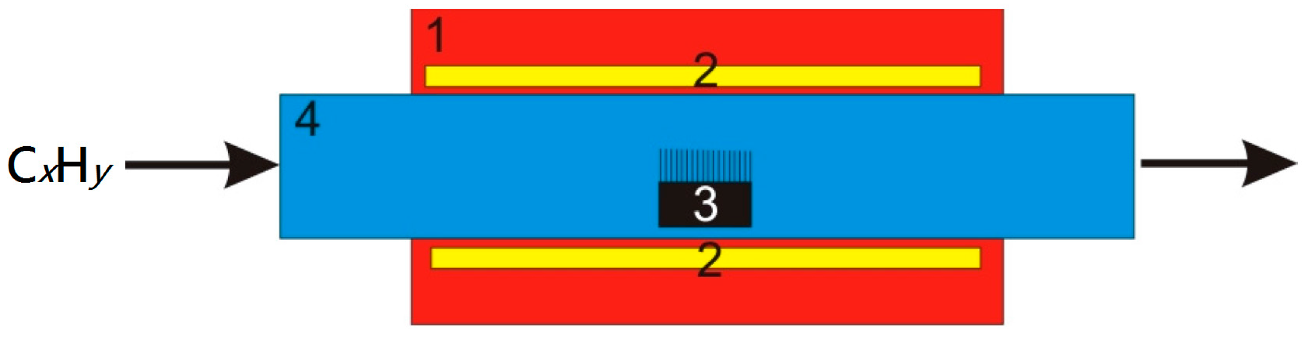
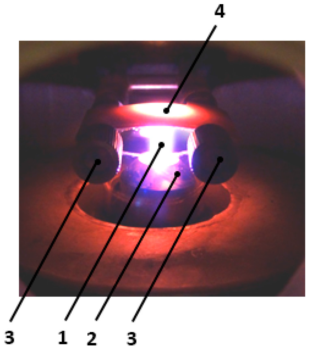
4. Experimental Setup for CNT Plasma Synthesis

In our laboratory, we built a reactor that allows the synthesis of carbon nanotubes on substrates with the application of microwave plasma. This reactor uses only one source of energy for simultaneously heating the substrate and breaking the bounds of the reaction gases. The substrate for the synthesis was made of stainless steel (1.4310) with thicknesses of 0.005, 0.01, 0.02, 0.05 mm, respectively. The substrate temperature (1000–1300 K) was controlled by the pyrometer. Its electric output signal was used in the loop for temperature control by tuning the microwave plasma power supply (max. 800 W). A mixture of argon and nitrogen was supplied axially to the microwave plasma nozzle. A mixture of argon, nitrogen, hydrogen and ethylene was introduced orthogonally to the plasma jet. The reactor setup is shown in Figure 2, a block diagram of the processing line in Figure 3 and a photo of the reactor in Figure 4.

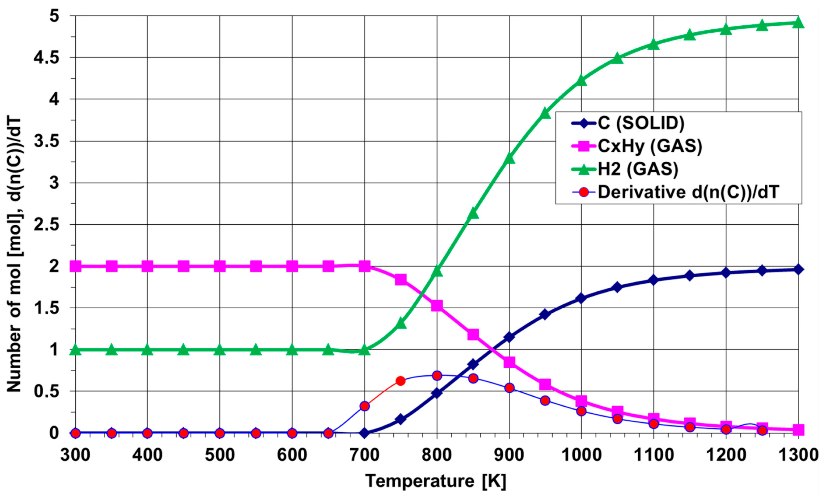
5. Thermal Decomposition of Gaseous Reagents

The synthesis process is composed of several stages such as venting, substrate annealing, and chemical reduction with hydrogen. Every step has its own range of allowed parameters (gas flow, time and temperature). At the beginning of the work, some computer simulations were conducted. During these calculations, the flow ranges of hydrogen, ethylene, acetylene, methane and other gaseous reagents were considered. Figure 5 shows the thermal decomposition of the mixture of two gases: 1000 sccm of ethylene and 3000 sccm of hydrogen. This proportion was commonly used in our research. It was concluded that from a thermodynamic point of view, the temperature for which there is a maximum of the first derivative of d(n(C))/dT shows the optimal point in which the separation of solid carbon in the reaction of the spontaneous decomposition of hydrocarbons is expected.
The temperature of 800 K is the minimum value to obtain carbon in a solid stage that is suitable for synthesis of carbon nanotubes.
Completed simulations are consistent with the data presented in the literature. For the purpose of comparison, Table 1 presents a review of the synthesis conditions found in the literature.

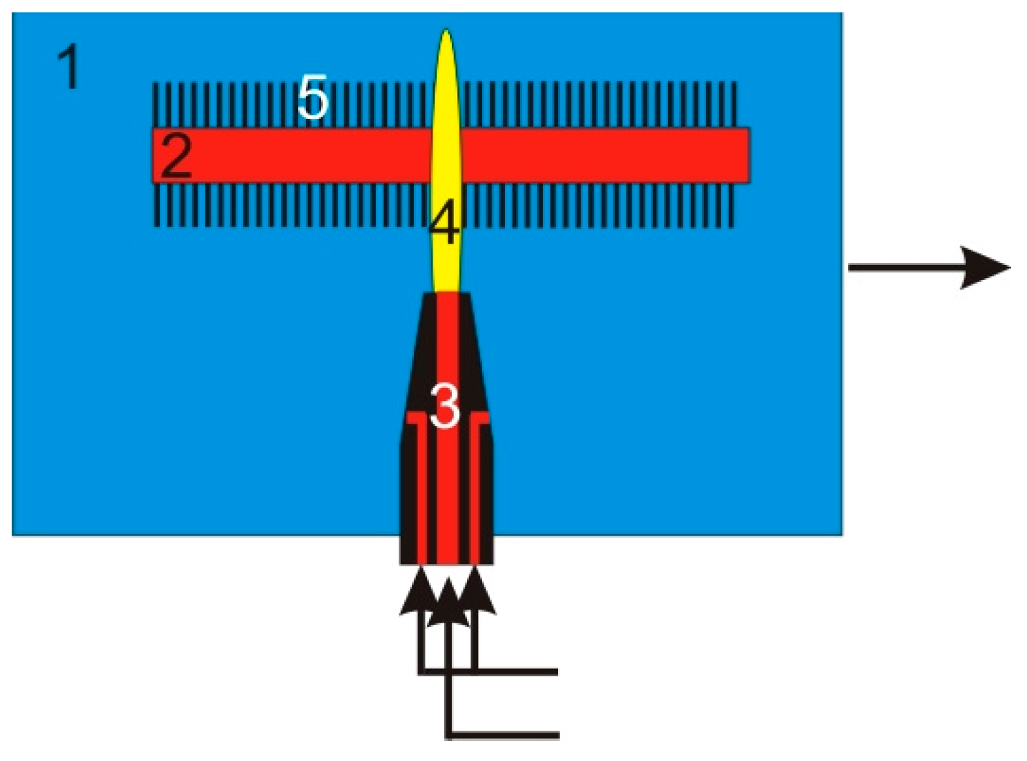
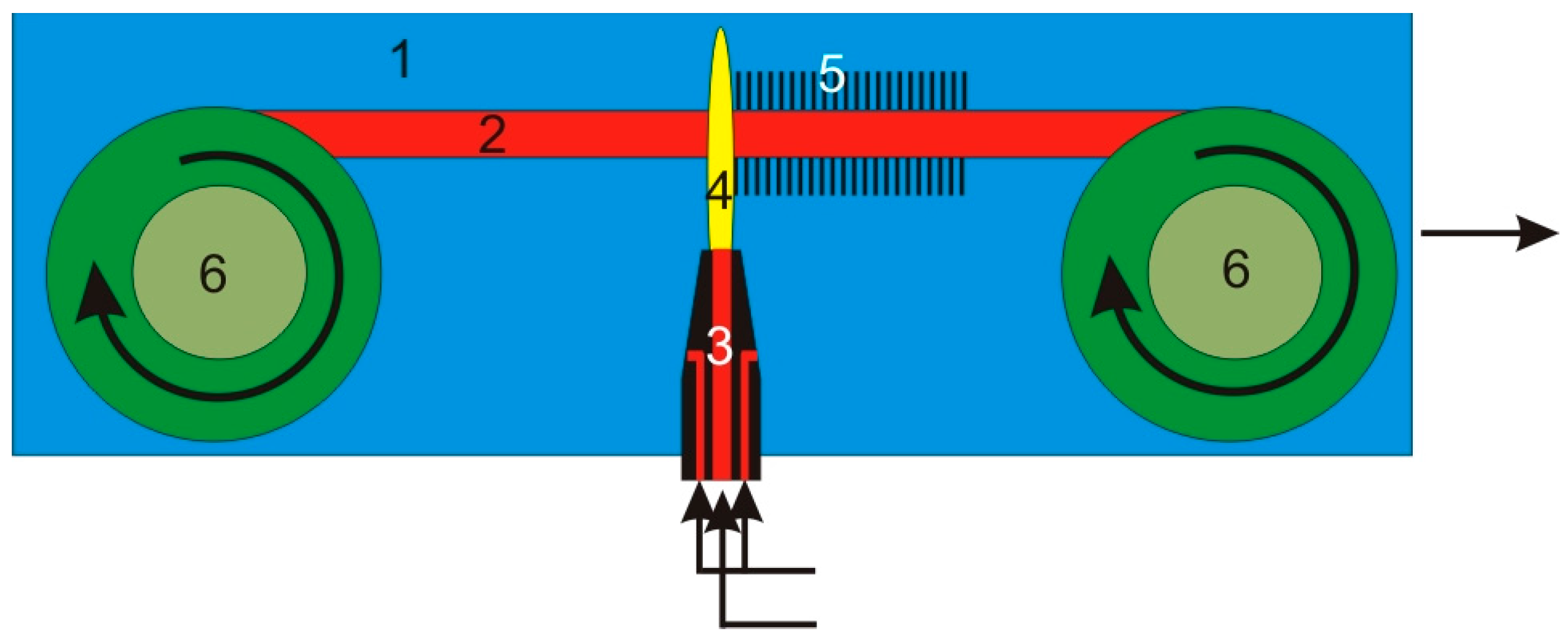
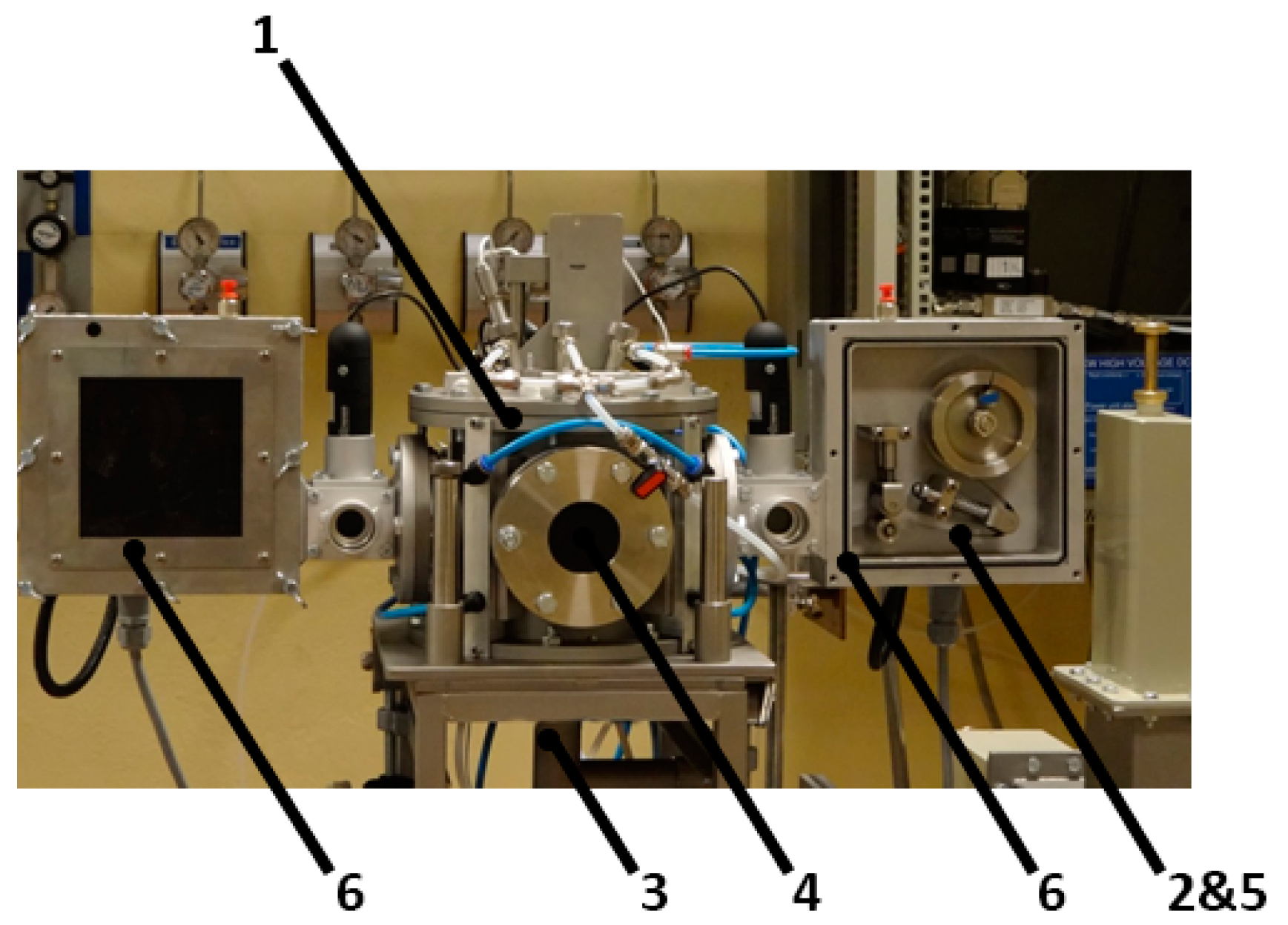
6. Experimental Setup for Continuous CNT Synthesis
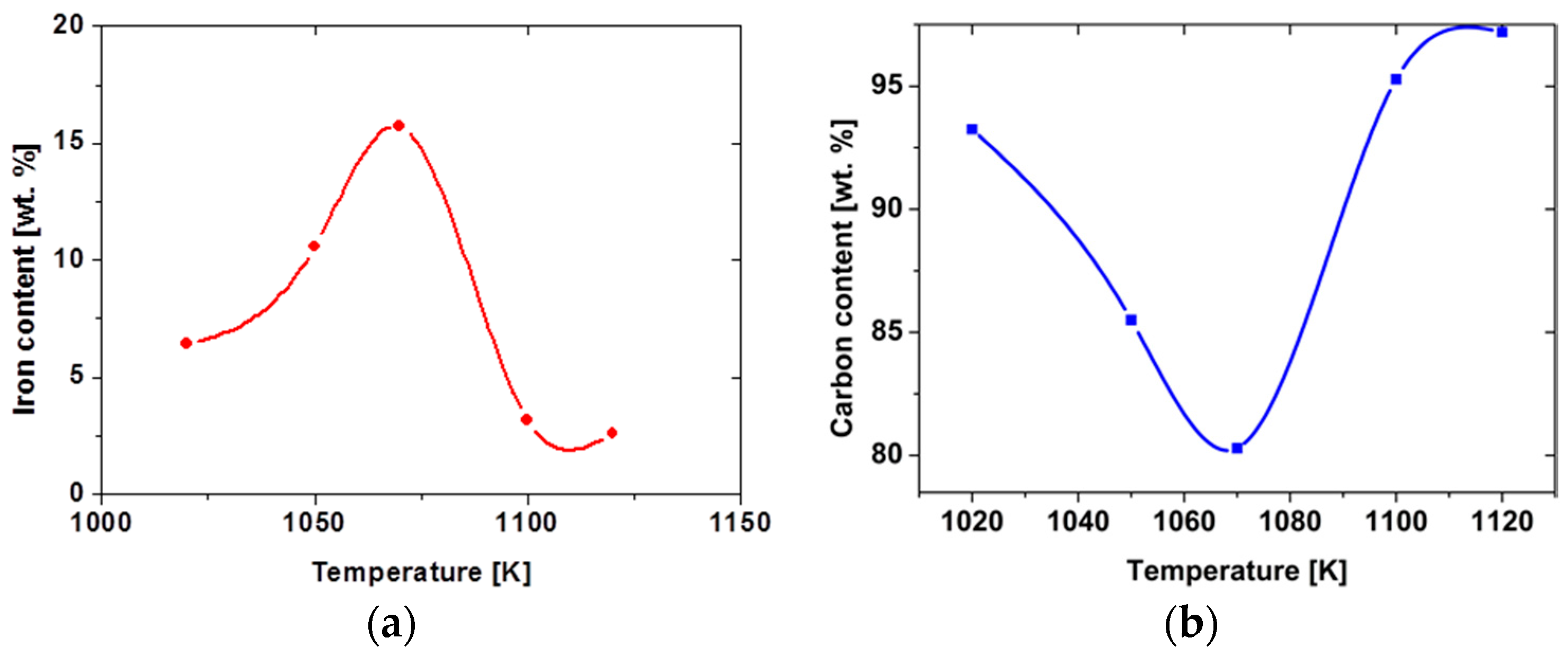
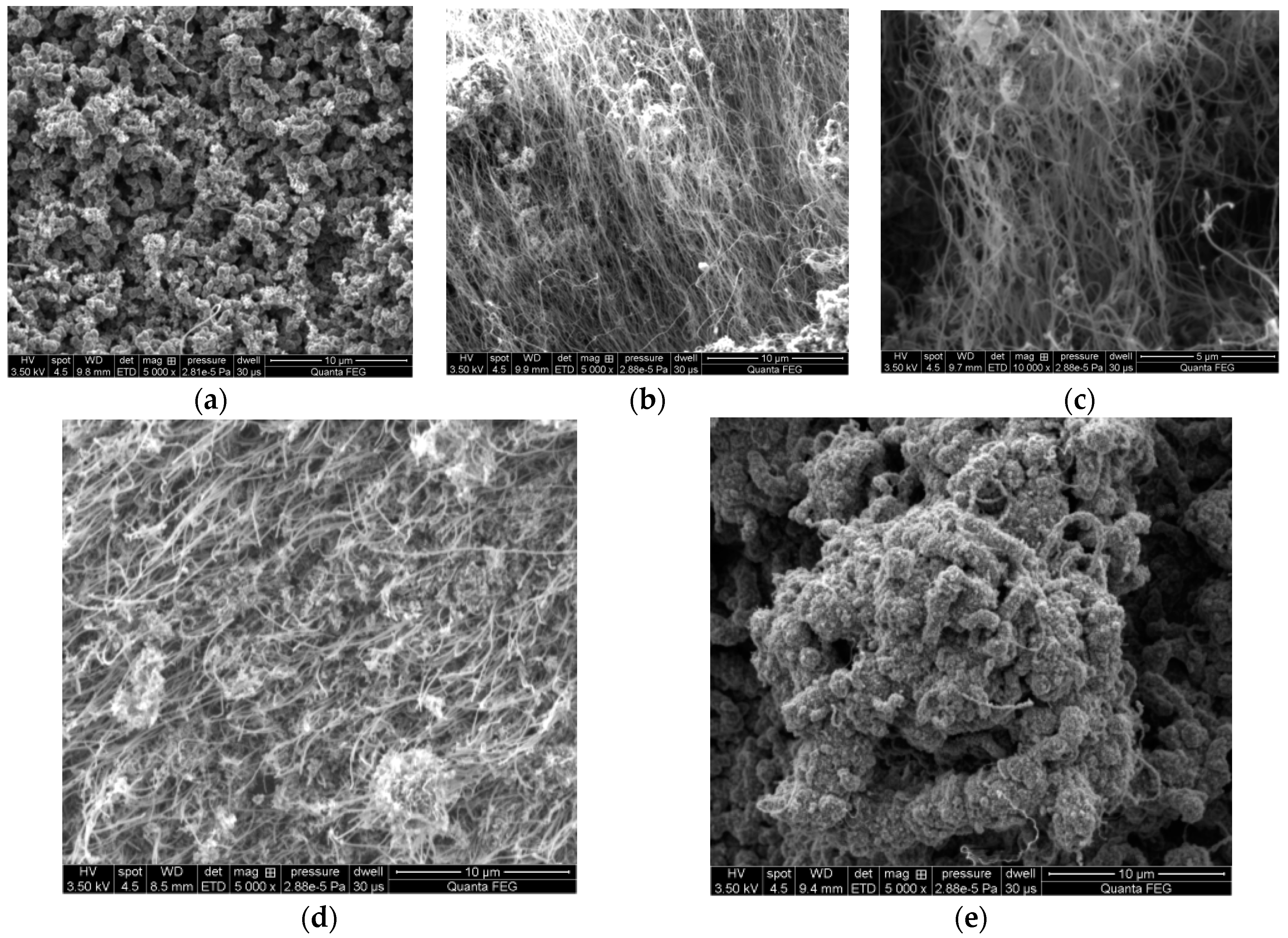
The reactor described in Section 4 can receive single samples only. The design presented below is an upgrade of the previous design which allows continuous movement of the metal substrate. The general principles of the reactor working are presented in Figure 6.
In Figure 7, the photo of the real system is shown. The synthesis of carbon nanotubes took place in the chamber on a metal strip (stainless steel) prepared by depositing a catalyst layer on the strip surface. The system has two moving tape cassettes supplying the reaction chamber with the substrate strip.
The synthesis of carbon nanotubes took place in a stainless steel chamber (purged 30 min with air plasma before growth started) on a metal substrate, which is ideal for this purpose. Argon (purity: O2 < 2 ppm, N2 < 5 ppm, H2O < 2 ppm, CH4 < 0.5 ppm, CO < 0.5 ppm, CO2 < 0.5 ppm) and nitrogen (purity: O2 < 2 ppm, H2O < 3 ppm) were used as the plasma gases whereas hydrogen (purity: O2 < 2 ppm, N2 < 3 ppm, H2O < 5 ppm, CxHy < 0.5 ppm) and ethylene (purity: O2 < 15 ppm, N2 < 50 ppm, CxHy < 450 ppm) provided carbon for the formation of CNTs. Carbon-carrying gas was supplied through a microwave plasma nozzle where it was decomposed. Plasma heated the substrate with a catalyst applied on the surface. The catalyst, ferrocene, was firstly dissolved in xylene. The surface was painted by this fluid in a dip-coating mode before the process started. The temperature of the substrate was controlled by the IR thermometer. The substrate moving speed over the plasma jet ranged from 0.01 m/h up to 0.1 m/h. Figure 7 shows the photo of the reactor.

7. Results

For the synthesis of carbon nanotubes, the stainless steel 1.4310 (1.4310-X10CrNi) cold-rolled was used. Its density was 7.9 kg/dm3, with a specific heat of 500 J/(kgK), a thermal conductivity of 15 W/(mK), a resistivity of 0.73 (mm2)/m, and it consisted of 17% Cr, 7% Ni, 0.05%–0.15% C, <2.00% Si, <2.00% Mn, <0.045% P, <0.015% S, 16.00%–19.00% Cr, 6.0%–9.5% Ni, <0.80% Mo.
The following methods of making the catalyst layers on the substrate surface were used:
  • chemical methods: coating the steel strip (substrate) with a layer of an antioxidant, e.g., Al2O3 applied in a dip-coating manner, followed by the application of an oxide catalyst layer such a Fe2O3 on the top,
  • treatment of the substrate surface with a ferrocene catalyst. Ferrocene evaporates from the source placed inside the reactor chamber which is a currently patented method by the paper authors.
One can see Scanning Electron Microscope (SEM) micrographs of deposits corresponding to different process temperatures (Figure 8a–e) within the 100 K range below. In order to present these relationships, adequate SEM images were selected, allowing observation of the process products.
The research results proved that the carbon nanotubes were synthesized on the steel surface at temperatures ranging from 1020 K to 1120 K (Figure 8a–e). Temperatures outside of described range did not allow CNT synthesis.
It could be noted that the most desirable synthesis temperature range is from 1050 K to 1070 K. Both 1050 K and 1070 K temperatures resulted in carbon nanotubes growing in the form of a “carpet” perpendicular to carpet’s base.
For chemical composition and structural examination, transmission electron microscopy (TEM—Tesla BS 512 with YAG camera, Pardubice, Czechoslovakia), energy-dispersive X-ray spectroscopy (EDX), and thermogravimetry (TGA—TA Instruments 2950 TGA HR apparatus, New Castle, DE, USA) techniques were used.
EDX analysis results (obtained using a FEI Quanta 200 FEG Mark II scanning electron microscope (New Castle, DE, USA) with an EDS Oxford INCA Energy System 250 spectrometer, Hillsboro, OR, USA) for CNT samples synthesized above the temperature range are shown in Figure 9a,b. Results presented on the plots are average values calculated for 10 samples synthesized under the same experimental conditions. Only Fe and C elements were analyzed, since other elements’ signals were the steel strip (CNT base) elements’ signals.
Significant data from EDX analysis proves a high carbon level for all samples and a high iron content, especially for the 1070 K (almost 20 wt. %) synthesis temperature sample. Figure 10 shows one of the EDS analysis results, which the average values shown on the plots in Figure 9 were calculated from.
As a complement to the EDX analysis, the TGA technique was used. In Figure 11a,b, typical thermographs for 1050 K and 1070 K are shown.
It may be noticed that the residue values were similar to the iron content achieved by EDX analysis. Also, maximum speed oxidation peaks for the examined samples lie in the 870–930 K temperature range and are similar to those described in the literature [56] as typical for multiwalled carbon nanotubes. The TEM examination of 1050 K and 1070 K samples revealed a multiwalled CNT structure and Fe nanoparticles encapsulated inside the MWCNTs (Figure 12).

8. Conclusions

The experimental results proved that the continuous synthesis of CNTs on a metal strip using a microwave thermal plasma reactor at atmospheric pressure can be done. Using analytical and diagnostic techniques let us hypothesize that successful growth of MWCNTs took place. The presence of multiwalled carbon nanotubes in the tested material was confirmed by both TGA and TEM experimental results. TGA showed oxidation temperatures typical for MWCNTs and, also, with EDX examination, provided information about the Fe content. Fe placement in CNTs is very meaningful for future applications of the obtained product. TEM analysis showed successful Fe encapsulation, which opens the way for medical applications of nanocontainers, i.e., in cancer therapy.

Acknowledgments

The research work has been financed from the budget of science as a research project No. N R01 0016 10 and No. PBS2/A5/31/2013.

Author Contributions

Lukasz Szymanski, Grzegorz Raniszewski, Zbigniew Kolacinski participated in designing, modelling and construction of the research set-up. All authors discussed the structure of the manuscript. Lukasz Szymanski was a leader in experimental sections. He managed the construction of the research set-up and he made experiments and measurements. He is the main author of the manuscript. Slawomir Wiak was an editor and reviewer of the manuscript. Lukasz Pietrzak was responsible for data analysis and carbon nanotubes characterization.

Conflicts of Interest

The authors declare no conflict of interest.

References

  1. Krätschmer, W.; Lamb, L.D.; Fostiropoulos, K.; Huffman, D.R. Solid C60: A new form of carbon. Nature 1990, 347, 354–356. [Google Scholar] [CrossRef]
  2. Kolacinski, Z.; Szymanski, L.; Raniszewski, G. Anode plasma jet behavior in CNTs deposit growth. In Proceedings of the 17th International Collegium on Plasma Processes, Marseille, France, June 2009.
  3. Raniszewski, G.; Szymanski, L.; Kolacinski, Z. Carbon nanotubes synthesis by electric arc plasma with external magnetic field. In Proceedings of the 4th International Conference Nanocon, Brno, Czech, 23–25 October 2012.
  4. Szymanski, L.; Kolacinski, Z.; Raniszewski, G. Reaktor plazmowy z łukiem wirującym [The plasma reactor using rotating arc]. Prz. Elektrotech. 2012, 88, 118–122, [in Polish]. [Google Scholar]
  5. Szymanski, L.; Raniszewski, G.; Kolacinski, Z. Magnetic Field Controlled CNTs Synthesis. In An Electrical Arc, Book of Contributed Papers—Hakone XIII; Lublin University of Technology: Kazimierz Dolny, Poland, 2012; pp. 268–270. [Google Scholar]
  6. Anazawa, K.; Shimotani, K.; Manabe, C.; Watanabe, H.; Shimizu, M. High-purity carbon nanotubes synthesis method by an arc discharging in magnetic field. Appl. Phys. Lett. 2002, 81, 739. [Google Scholar] [CrossRef]
  7. Keidar, M.; Levchenko, I.; Arbel, T.; Alexander, M.; Waas, A.M.; Ostrikov, K. Increasing the length of single-wall carbon nanotubes in a magnetically enhanced arc discharge. Appl. Phys. Lett. 2008, 92, 043129. [Google Scholar] [CrossRef]
  8. Gruenberger, T.M.; Gonzalez-Aguilar, J.; Fabry, F.; Fulchieri, L.; Grivei, E.; Probst, N.; Flamand, G.; Okuno, H.; Charlier, J.C. Production of carbon nanotubes and other nanostructures via continuous 3-phase AC plasma processing. Fuller. Nanotub. Carbon Nanostruct. 2004, 12, 571–581. [Google Scholar] [CrossRef]
  9. Matsuura, T.; Watanabe, T. A new type of arc plasma reactor with 12-phase alternating current discharge for synthesis of carbon nanotubes. Thin Solid Films 2007, 515, 4240–4246. [Google Scholar] [CrossRef]
  10. Okuno, H.; Grivel, E.; Fabry, F.; Gruenberger, T.M.; Gonzalez-Aguilar, J.J.; Palnichenko, A.; Fulchieri, L.; Probst, N.; Chalier, J.C. Synthesis of carbon nanotubes and nano-necklaces by thermal plasma process. Carbon 2004, 42, 2543–2549. [Google Scholar] [CrossRef]
  11. Guo, T.; Nikolaev, P.; Rinzler, A.G.; Tomanek, D.; Colbert, D.T.; Smalley, R.E. Self assembly of tubular fullerenes. J. Phys. Chem. 1995, 99, 10694. [Google Scholar] [CrossRef]
  12. Guo, T.; Nikolaev, P.; Thess, A.; Colbert, D.T.; Smalley, R.E. Catalytic growth of single-walled nanotubes by laser vaporization. Chem. Phys. Lett. 1995, 243, 49–54. [Google Scholar] [CrossRef]
  13. Hernandez, E.; Ordejon, P.; Boustani, I.; Rubio, A.; Alonso, J.A. Tight binding molecular dynamics studies of boron assisted nanotube growth. J. Chem. Phys. 2000, 113, 3814–3821. [Google Scholar] [CrossRef]
  14. Sun, L.F.; Mao, J.M.; Pan, Z.W.; Chang, B.H.; Zhou, W.Y.; Wang, G.; Qian, L.X.; Xie, S.S. Growth of straight nanotubes with a cobalt-nickel catalyst by chemical vapor deposition. Appl. Phys. Lett. 1999, 74, 644–646. [Google Scholar] [CrossRef]
  15. Thess, A.; Lee, R.; Nikolaev, P.; Dai, H.; Petit, P.; Robert, J.; Xu, C.; Lee, Y.H.; Kim, S.G.; Andrew, G.; et al. Crystalline ropes of metallic carbon nanotubes. Science 1996, 273, 483–487. [Google Scholar] [CrossRef] [PubMed]
  16. Yudasaka, M.; Komatsu, T.; Ichihashi, T.; Iijima, S. Single-wall carbon nanotube formation by laser ablation using double-targets of carbon and metal. Chem. Phys. Lett. 1997, 278, 102–106. [Google Scholar] [CrossRef]
  17. Yudasaka, M.; Sensui, N.; Takizawa, M.; Bandow, S.; Ichihashi, T.; Iijima, S. Formation of single-wall carbon nanotubes catalyzed by Ni separating from Y in laser ablation or in arc discharge using a C target containing a NiY catalyst. Chem. Phys. Lett. 1999, 312, 155–160. [Google Scholar] [CrossRef]
  18. Yudasaka, M.; Yamada, R.; Sensui, N.; Wilkins, T.; Ichihashi, T.; Iijima, S. Mechanism of the effect of NiCo, Ni and Co catalysts on the yield of singlewall carbon nanotubes formed by pulsed Nd:YAG laser ablation. J. Phys. Chem. B 1999, 103, 6224–6229. [Google Scholar] [CrossRef]
  19. Yudasaka, M.; Zhang, M.; Iijima, S. Porous target enhances production of single-wall carbon nanotubes by laser ablation. Chem. Phys. Lett. 2000, 323, 549–553. [Google Scholar] [CrossRef]
  20. Bernier, P.; Laplaze, D.; Auriol, J.; Barbedette, L.; Flamant, G.; Lebrun, M.; Brunelle, A.; Della-Negra, S. Production of fullerenes from solar energy. Synth. Met. 1995, 70, 1455–1456. [Google Scholar] [CrossRef]
  21. Chibante, L.P.F.; Thess, A.; Alford, J.M.; Diener, M.D.; Smalley, R.E. Solar generation of the fullerenes. J. Phys. Chem. 1993, 97, 8696–8700. [Google Scholar] [CrossRef]
  22. Fields, C.L.; Pitts, J.R.; Hale, M.J.; Bingham, C.; Lewandowski, A.; King, D.E. Formation of fullerenes in highly concentrated solar flux. J. Phys. Chem. 1993, 97, 8701–8702. [Google Scholar] [CrossRef]
  23. Fields, C.L.P., Jr.; Mischler, D.; Bingham, C.; Lewandowski, A.; Schultz, D.L.; Bekkedahl, T.A.; Jones, K.M.; Heben, M.J. An update on solar fullerene production at the national renewable energy Laboratory. In Proceedings of the 8th International Symposium on Solar Thermal Concentrating Technologies, Köln, Germany, 6–11 October 1996.
  24. Heben, M.J.; Bekkedahl, T.A.; Schultz, D.L.; Jones, K.M.; Dillon, A.C.; Curtis, C.J.; Bingham, C.; Pitts, J.R.; Lewandowski, A.; Fields, C.L. Production of single-wall carbon nanotubes using concentrated sunlight. In Proceedings of the Symposium on Recent Advances in the Chemistry and Physics of Fullerenes and Related Materials; Electrochemical Society Inc.: Pennington, UK, November 1996. [Google Scholar]
  25. Hsu, W.K.; Hare, J.P.; Terrones, M.; Kroto, H.W.; Walton, D.R.M.; Harris, P.J.F. Condensed-phase nanotubes. Nature 1995, 377, 687. [Google Scholar] [CrossRef]
  26. Hsu, W.K.; Terrones, M.; Hare, J.P.; Terrones, H.; Kroto, H.W.; Walton, D.R.M. Electrolytic formation of carbon nanostructures. Chem. Phys. Lett. 1996, 262, 161–166. [Google Scholar] [CrossRef]
  27. Laplaze, D.; Bernier, P.; Barbedette, L.; Lambert, J.M.; Brunelle, A.; Della-Negra, S.; Flamant, G.; Lebrun, M. Production of fullerenes from solar energy: The Odeillo experiment. Comptes Rendus de l'Acad. des Sci. Ser. 2. 1994, 318, 733–738. [Google Scholar] [CrossRef]
  28. Laplaze, D.; Bernier, P.; Flamant, G.; Lebrun, M.; Brunelle, A.; Della-Negra, S. Preparation of fullerenes using a solar furnace. Synth. Met. 1996, 77, 67–71. [Google Scholar] [CrossRef]
  29. Laplaze, D.; Bernier, P.; Journet, C.; Sauvajol, J.L.; Bormann, D.; Flamant, G.; Lebrun, M. The use of solar energy for the production of fullerenes and porous silicon. J. Phys. 1997, 7, 463–472. [Google Scholar] [CrossRef]
  30. Laplaze, D.; Bernier, P.; Journet, C.; Vie, V.; Flamant, G.; Lebrun, M. Carbon sublimation using a solar furnace. Synth. Met. 1997, 86, 2295–2296. [Google Scholar] [CrossRef]
  31. Laplaze, D.; Bernies, J.; Journet, C.P.; Vie, V.; Flamant, G.; Philippot, E.; Lebrun, M. Evaporation of graphite using a solar furnace: Production of fullerenes. In Proceedings of the 8th International Symposium on Solar Thermal Concentrating Technologies, Köln, Germany, 6–11 October 1996.
  32. Jeong, S.-H.; Lee, O.-J.; Lee, K.-H.; Oh, S.H.; Park, C.-G. Preparation of aligned carbon nanotubes with prescribed dimensions, template synthesis and sonication cutting approach. Chem. Mater. 2002, 14, 1859–1862. [Google Scholar] [CrossRef]
  33. Katoh, R.; Tasaka, Y.; Sekreta, E.; Yumura, M.; Ikazaki, F.; Kakudate, Y.; Fujiwara, S. Sonochemical production of a carbon nanotube. Ultrason. Sonochem. 1999, 6, 185–187. [Google Scholar] [CrossRef]
  34. Cho, W.S.; Hamada, E.; Kondo, Y.; Takayanagi, K. Synthesis of carbon nanotubes from bulk polymer. Appl. Phys. Lett. 1996, 69, 278–279. [Google Scholar] [CrossRef]
  35. HulicÏovµ, D.; Hosoi, K.; Kuroda, S.I.; Abe, H.; Oya, A. Carbon nanotubes prepared by spinning and carbonizing fine core±shell polymer microspheres. Adv. Mater. 2002, 14, 452–455. [Google Scholar]
  36. Jiang, J.; Feng, T.; Cheng, X.; Dai, L.; Cao, G.; Jiang, B.; Wang, X.; Liu, X.; Zou, S. Synthesis and growth mechanism of Fe-catalyzed carbon nanotubes by plasma-enhanced chemical vapor deposition. Nucl. Instrum. Methods Phys. Res. 2006, B244, 327–332. [Google Scholar] [CrossRef]
  37. Meyyappan, M.; Delzeit, L.; Cassell, A.; Hash, D. Carbon nanotube growth by PECVD: A review. Plasma Sour. Sci. Technol. 2003, 12, 205–216. [Google Scholar] [CrossRef]
  38. Minea, T.M.; Point, S.; Gohier, A.; Granier, A.; Godon, C.; Alvarez, F. Single chamber PVD/PECVD process for in situ control of the catalyst activity on carbon nanotubes growth. Surf. Coat. Technol. 2005, 200, 1101–1105. [Google Scholar] [CrossRef]
  39. Blase, X.; Charlier, J.C.; De Vita, A.; Car, R.; Redlich, P.; Terrones, M.; Hsu, W.K.; Terrones, H.; Carroll, D.L.; Ajayan, P.M. Boron-mediated growth of long helicity-selected carbon nanotubes. Phys. Rev. Lett. 1999, 83, 5078–5081. [Google Scholar] [CrossRef]
  40. Yabe, Y.; Ohtake, Y.; Ishitobi, T.; Show, Y.; Izumi, T.; Yamauchib, H. Synthesis of well-aligned carbon nanotubes by radio frequency plasma enhanced CVD method. Diam. Relat. Mater. 2004, 1292–1295. [Google Scholar] [CrossRef]
  41. Ebbesen, T.W. Carbon Nanotubes: Preparation and Properties; CRC Press: Boca Raton, FL, USA, 1997. [Google Scholar]
  42. Huczko, A. Nanorurki Węglowe: Czarne diamenty XXI wieku [Carbon Nanotubes - Black Diamonds of XXI century]; BEL Studio: Warszawa, Poland, 2004; [in Polish]. [Google Scholar]
  43. Iijima, S. Carbon nanotubes: Past, present, and future. Physica B 2002, 323, 1–5. [Google Scholar] [CrossRef]
  44. Kong, J.; Cassell, A.M.; Dai, H. Chemical vapor depositin of methane for single walled carbon nanotubes. Chem. Phys. Lett. 1998, 292, 567–574. [Google Scholar] [CrossRef]
  45. Moisala, A.; Nasibulin, A.G.; Kauppinen, E.I. The role of metal nanoparticles in the catalytic production of single-walled carbon nanotubes—A review. J. Phys. Condens. Matter 2003, 15, 3011. [Google Scholar] [CrossRef]
  46. Nagy, J.B.; Bister, G.; Fonseca, A.; Mehn, D.; Konya, Z.; Kiricsi, I.; Horvath, Z.E.; Biro, L.P. On the growth mechanism of single-walled carbon nanotubes by catalytic carbon vapor deposition on supported metal catalysts. J. Nanosci. Nanotechnol. 2004, 4, 326–345. [Google Scholar] [CrossRef] [PubMed]
  47. Przygocki, W.; Lochowicz, A. Fulereny i Nanorurki—Właściwości i Zastosowanie [Fulerens and Nanotubes – Properties and Application]; Wydawnictwo Naukowo-Techniczne: Warszawa, Poland, 2001; [in Polish]. [Google Scholar]
  48. Reich, S.; Thomsen, C.; Maultzsch, J. Carbon Nanotubes, 1st ed.; Wiley-Vch: Weinheim Germany, 2004. [Google Scholar]
  49. Rotkin, S.; Subramoney, S. Applied Physiks of Carbon Nanotubes. Fundamentals of Theory, Optics and Transport Devices; Springer: New York, NY, USA, 2005. [Google Scholar]
  50. Wang, Y.; Rybczynski, J.; Wang, D.Z.; Kempa, K.; Ren, Z.F.; Li, W.Z.; Kimball, B. Periodicity and alignment of large-scale carbon nanotubes arrays. Appl. Phys. Lett. 2004, 85, 4741–4743. [Google Scholar] [CrossRef]
  51. Wang, X.; Hu, Z.; Chen, X.; Chen, Y. Preparation of carbon nanotubes and nano-particles by microwave plasma-enhanced chemical vapor deposition. Scr. Mater. 2001, 44, 1567–1570. [Google Scholar] [CrossRef]
  52. Kondo, H.; Fukuoka, F.; Maruyama, T. Low temperature growth of single-walled carbon nanotubes from Pt catalysts under low ethanol pressure by alcohol gas source method. J. Nanotechnol. 2012, 2012, 690304. [Google Scholar] [CrossRef]
  53. Atiyah, M.R.; Awang Black, D.R.; Achamadun, F.; Achamad, I.S.; Mohd Yasin, F.; Yusoff, H.M. Low temperature growth of vertically aligned carbon nanotubes via floating catalyst chemical vapor depositon method. J. Mater. Sci. Technol. 2011, 27, 290–300. [Google Scholar] [CrossRef]
  54. Halonen, N.; Sápi, A.; Nagy, L.; Puskás, R.; Leino, A.; Mäklin, J.; Kukkola, J.; Tóth, G.; Wu, M.; Liao, H.; et al. Low-temperature growth of multi-walled carbon nanotubes by thermal CVD. Phys. Statut Solidi B 2011, 248, 2500–2503. [Google Scholar] [CrossRef]
  55. Lee, C.J.; Park, J.; Kim, J.M.; Huh, Y.; Lee, J.Y.; No, K.S. Low-temperature growth of carbon nanotubes by thermal chemical vapor deposition using Pd, Cr, and Pt as co-catalyst. Chem. Phys. Lett. 2000, 327, 277–283. [Google Scholar] [CrossRef]
  56. Mahajan, A.; Kingon, A.I.; Kukovecz, K.; Vilarinho, P. Studies on the thermal decomposition of multiwall carbon nanotubes under different atmospheres. Mater. Lett. 2013, 90, 165–168. [Google Scholar] [CrossRef]
Figure 1. Setup of CVD reactor for CNT synthesis where: 1—furnace; 2—furnace heating elements; 3—substrate with growing nanotubes; 4—reaction tube [41].
Nanomaterials 07 00045 g001
Figure 2. The general setup of the microwave plasma reactor where: 1—reaction chamber; 2—substrate with catalyst layer; 3—plasma nozzle; 4—plasma; 5—carbon nanotubes.
Nanomaterials 07 00045 g002
Figure 3. Block diagram of a test line where: 1—power supply; 2—generator; 3—circulator; 4—matching circuit, 5—reflectometer; 6—coaxial plasma head; 7—reaction chamber; 8—gas inlets; 9—cooling water.
Nanomaterials 07 00045 g003
Figure 4. Photo of reaction zone of the microwave plasma reactor for carbon nanotube (CNT) synthesis on a metal substrate where: 1—microwave plasma; 2—plasma head; 3—substrate feeder; 4—substrate.
Nanomaterials 07 00045 g004
Figure 5. Thermal decomposition of the mixture of 1000 sccm of ethylene with 3000 sccm of hydrogen.
Nanomaterials 07 00045 g005
Figure 6. Schematic diagram of the continuous microwave plasma system for CNT synthesis where: 1—reactor space; 2—substrate-metal strip; 3—microwave plasma head; 4—microwave plasma torch; 5—CNTs; 6—cassettes to move the metal substrate.
Nanomaterials 07 00045 g006
Figure 7. Photo of the plasma processing system where: 1—reactor chamber; 2—substrate-metal strip; 3—microwave plasma head; 4—microwave plasma torch (not visible); 5—CNTs (not visible); 6—cassettes to move the metal substrate.
Nanomaterials 07 00045 g007
Figure 8. SEM images of the steel with carbon nanotubes synthesized at different temperatures (a) 1020 K; (b) 1050 K; (c) 1070 K; (d) 1100 K; (e) 1120 K.
Nanomaterials 07 00045 g008
Figure 9. Plots of iron—(a) and carbon—(b) content versus synthesis temperature.
Nanomaterials 07 00045 g009
Figure 10. Energy-dispersive X-ray spectroscopy (EDX) analysis results for one of the specimens synthesized at 1070 K.
Nanomaterials 07 00045 g010
Figure 11. Thermogravimetry (TGA) thermographs of samples synthesized at (a) 1050 K; (b) 1070 K.
Nanomaterials 07 00045 g011
Figure 12. Transmission electron microscopy (TEM) images of Multi-Walled Carbon Nanotubes (MWCNTs) obtained during synthesis at (a) 1050 K; (b) 1070 K, respectively.
Nanomaterials 07 00045 g012
Table 1. Conditions for experimental reactions for the synthesis of carbon nanotubes (literature).
MethodsShort Description of the Synthesis ConditionsTemperatureReference
PECVDPressure of 5–10 torr, Ni catalyst, reagents: methane and ethane770 K[49]
PECVDReagents methane + hydrogen790 K[50]
PECVDReaction with alcohol720 K[51]
CVDReaction with benzene/ferrocene670/840 K[52]
CVDThe reaction with methanol, acetylene, and Co, Co/Fe, Ni/Co/Fe/Al2O3770 K[53]
CVDThe reaction of acetylene with NH3/H2, Fe/Ni/Co770–820 K[54,55]

