Ethanol-Mediated 2D Growth of Cu2O Nanoarchitectures on Nanoporous Cu Templates in Anhydrous Ethanol


1
Tech Institute for Advanced Materials and College of Materials Science and Engineering, Nanjing Tech University, Nanjing 210009, China
2
The Synergetic Innovation Center for Advanced Materials, Nanjing Tech University, Nanjing 210009, China
3
School of Materials and Science and Engineering, Nanjing University of Science and Technology, Nanjing 210094, China
*
Authors to whom correspondence should be addressed.
Nanomaterials 2018, 8(1), 18; https://doi.org/10.3390/nano8010018
Submission received: 5 December 2017
/
Revised: 26 December 2017
/
Accepted: 27 December 2017
/
Published: 31 December 2017
Abstract
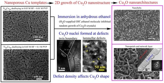
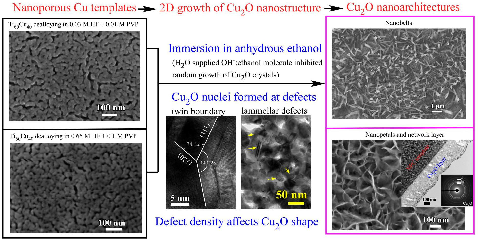
:Two types of cupric oxide (Cu2O) nanoarchitectures (nanobelts and nanopetal networks) have been achieved via immersion nanoporous copper (NPC) templates in anhydrous ethanol. NPC templates with different defect densities have been prepared by dealloying amorphous Ti60Cu40 ribbons in a mixture solution of hydrofluoric acid and polyvinylpyrrolidone (PVP) with different ratios of HF/PVP. Both a water molecule reactant acting as OH− reservoir and the ethanol molecule serving as stabilizing or capping reagent for inhibiting the random growth of Cu2Oplayed a role of the formation of 2-dimensional Cu2O nanoarchitectures. Cu2O nanobelts are preferred to form in anhydrous ethanol on the NPC templates from Ti60Cu40 ribbons dealloying in the solution with low HF concentration and small addition of PVP; and Cu2O nanopetals are tended to grow in anhydrous ethanol from the NPC templates from Ti60Cu40 ribbons dealloying in the solution with high HF concentration and large addition of PVP. With increasing the immersion time in anhydrous ethanol, Cu2O nanopetals united together to create porous networks about 300 nm in thickness. The defect sites (i.e., twin boundary) on nanoporous Cu ligaments preferentially served as nucleation sites for Cu2O nanocrystals, and the higher defect density leads to the formation of uniform Cu2O layer. Synergistic effect of initial microstructure of NPC templates and stabilizing agent of ethanol molecule results in different Cu2O nanoarchitectures.
1. Introduction
Cuprous oxide (Cu2O) is a p-type semiconductor with a direct band gap of 2.17 eV. Owing to the quantum size effects, Cu2O nanoparticles show many superior optical, electrical, and photo-electrochemical properties [1,2,3,4,5,6,7,8,9]. Because the shape and size of metal oxides directly affect their physical and chemical properties, many efforts have been devoted to the synthesis of uniform cuprous oxide with various structure and morphologies during the past decades [1,2,3,4]. Hydrazine [5], sodium borohydride [6], ethylene glycol [7], glucose [8], 2,5-dimethoxyaniline [9] or polyvinylpyrrolidone (PVP) [4] is frequently used to synthesize Cu2O particles, but rare report is found using water as a reducing agent. Many shapes of Cu2O nanostructures have been done last several decades, such as nanocubes via a surfactant-assisted solution-phase route [10,11], nanocages by PVP-mediated polyol process [12,13,14], microspheres by one-pot solvent-thermal method [15], nanorods by solvent-thermal method [16,17], nanowires by a hydrothermal approach [9,18], nanooctahedra through a reducing complex solution approach [19,20], nanoflowers via a polymer-assisted solution-phase route [6], double tower-tip-like Cu2O nanostructures in water/oil microemulsion [20], nanobranches by an additives-assisted electrochemical deposition [21,22,23,24,25], etc. Proper combination of the precursor, template, solvent, reductants helps to tailor the crystal habit via preferential adsorption of reactants, nucleation and growth of nanoarchitectures. Nanoporous noble metals with a high surface area and conductivity, such as Pt, Pd, Au, Ag, [26,27,28] have been fabricated via dealloying process. In order to reduce the cost of the nanoporous noble metals, many cost-effective metals with porous structures, such as Ni and Cu [29,30,31], have also been fabricated. The relative rough morphology with large nanopores and coarse ligaments restricts the potential application of nanoporous Cu in the catalytic and energy fields. Many efforts have been contributed to refine nanoporous Cu by alloying of third elements with a low surface diffusivity [30,32] and an introduction of PVP macromolecule into dealloying solution [33,34] down to few tenth nanometers through controlling the surface diffusion and the rearrangement of Cu adatoms. Cu2O layer readily forms due to the existence of the highly active sites on the Cu ligaments and exhibits superior performances of photodegradation [35] and Li-ion battery [36]. However, the other-shape Cu2O formation on nanoporous Cu has been rarely reported.
In the present study, the effect of the combination of the nanoporous templates and ethanol as a stabilizing agent on the formation of the different shapes of Cu2O nanostructures has been investigated. The formation mechanism of Cu2O nanobelts and nanopetal networks was discussed on the basis of the growth of Cu2O nanobelts in anhydrous ethanol from analysis of X-ray diffractometry, scanning electron microscopy, transmission electron microscopy, X-ray photoelectron spectroscopy.
2. Materials and Methods
Nanoporous Cu (NPC) templates were prepared by dealloying the melt-spun Ti60Cu40 ribbons with a width of 2 mm and thickness of ~25 μm in the mixture solution of 0.03 M HF and 0.01 M PVP (1 g/L), and 0.65 MHF and 0.1 MPVP (10 g/L). The detail information of the experiments has been described previously [29,34]. The molecular weight of polyvinylpyrrolidone (PVP: (C6H9NO)n, Sigma-Aldrich Co. Ltd., Shanghai, China) was 55,000 g·mol−1 in the present experiments. Nanoporous Cu templates (NPC templates) were then immersed into purchased chemical reagent anhydrous ethanol (purity > 99.5 mass%, AR, Sinopharm Chemical Reagent Co. Ltd., Shanghai, China) for 24, 120 h. The water concentration of the anhydrous ethanol was about 0.5 mass%. The surface morphology of Cu2O nanoarchitectures were observed by scanning electron microscope (SEM, JEOL, FIB4610, JEOL Ltd., Tokyo, Japan). The as-spun ribbons, dealloyed ribbons and NPC templates after immersion in anhydrous ethanol were characterized by X-ray diffractometor (XRD, Rigaku, RINT-4200, Rigaku Co., Tokyo, Japan). The microstructure of NPC templates and the Cu2O nanostructures was observed by a transmission electron microscope (TEM, JEOL, HC2100, JEOL Ltd., Tokyo, Japan) and a high-resolution transmission electron microscope (HRTEM, JEOL, ARM200, JEOL Ltd., Tokyo, Japan). The TEM samples were prepared by focused ion beam milling (FIB, JEOL, Dual beam FIB 4610, JEOL Ltd., Tokyo, Japan) after coating with a protective carbon layer and a W deposition layer to lessen the damage of the surface layer. The surface chemical state was analyzed by an X-ray photoelectron spectroscope (XPS, Shimadzu Kratos, AXIS-Ultra DLD, Tokyo, Japan) with a monochromatized Al Kα radiation source (1486.6 eV).
3. Results and Discussion
3.1. 2D Growth of Cu2O Nanobelts in Anhydrous Ethanol on NPC Templates from Ti60Cu40 Ribbons Dealloying in 0.03 M HF and 0.01 M PVP Solution
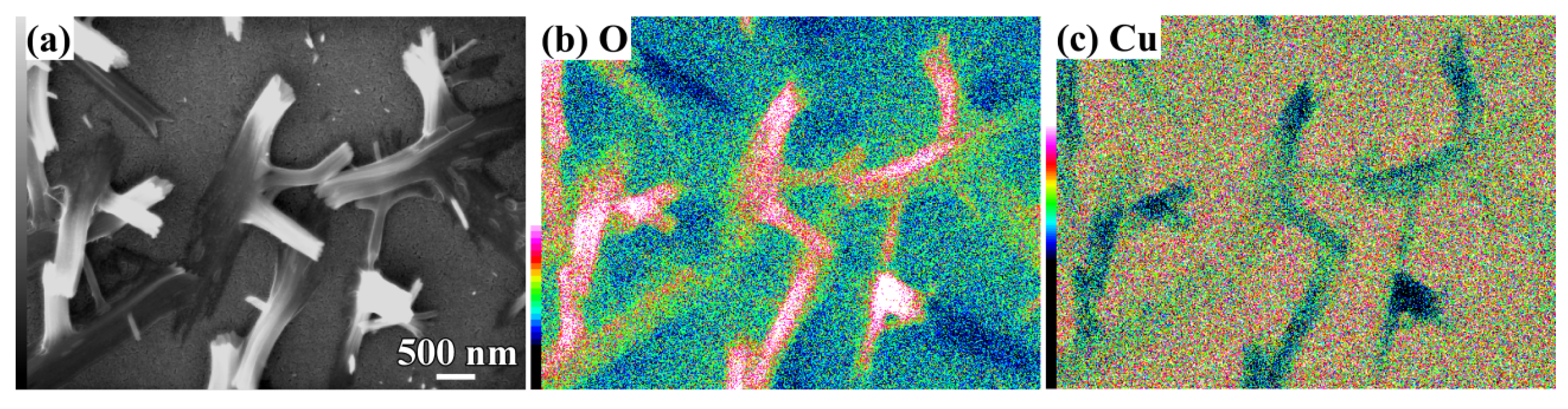
The crystalline state of the chemical composition of NPC templates and the characterization of the initial Ti60Cu40 precursor alloys have been reported previously [29,34]. The crystalline state of surface oxides on NPC templates after immersion of 120 h in anhydrous ethanol were confirmed by XRD (Figure 1a). The black and gray vertical lines stand for the peak position and intensity of Cu (JCPDF card No.: 02-1225) and Cu2O (JCPDF card No.: 74-1230). After immersing NPC templates in anhydrous ethanol for 120 h, two main diffraction peaks centered at 2θ = 36.5°, 61.5° were assigned to Cu2O (111) (220), and another diffraction peak from Cu2O (200) was overlapped by the diffraction peaks of fcc Cu around 2θ = 42°. The XRD data demonstrated that the Cu2O architectures formed after a free immersion in anhydrous ethanol for 120 h were crystalline. Meanwhile, three diffraction peaks from NPC templates were also detected and assigned to Cu (111), (200) and (220), which might be due to the partial coverage of Cu2O. As shown in Figure 2a, many belt-shaped species formed and covered partially the surface of NPC templates although the distribution was not uniform. The immersion products in this case are hereafter referred as nanobelts. The magnified morphology shows that the nanobelts with different sizes formed in the different region. In the middle regions, the belts have a characteristic width size of about 480 nm and the branch length of about few micrometers. The thickness of the belts isvery small since many of them are transparent under the secondary electron observation. Most of nanobelts have several branches shown in Figure 2b. On the other regions, the nanobelts with narrower branches with a width of about 160 nm became interlaced together and covered more than that in the middle region. The end regions of many belts exhibit serrated characteristics which are considered to be resulted from the fracture of the long belts due to removal of the residual chemicals via washing of water and ethanol. To some extent, this is also a supportive evidence for the nanobelts with a very thin thickness. It is worth noting that the underlying nanoporous structure covered by the larger nanobelts has a finer nanoporous structure in comparison to that covered by the finer nanobelts. This fact might be linked with the different distribution of the defects in different nanoporous structures. The elemental mapping profiles of the nanobelts in Figure 3 shows that the nanobelts consisted of O and Cu. The oxygen concentration of the nanobelts was higher than that of the underlying NPC templates. The chemical composition of the nanobelts can be confirmed to be Cu2O on the basis of the corresponding XRD pattern in Figure 1 and Figure 3. In Figure 3a, the main branches grew up from NPC templates and some small secondary branches grew from the main branches.
The roots of the Cu2O nanobelts and their interfacial regions seemed growing up at specific sites. In order to know the growth mechanism of Cu2O nanobelts, the cross-sectional TEM observation was performed. Several Cu2O nanobelts can be seen in the middle parts in Figure 4a. The root of Cu2O nanobelts in Figure 4b,d shows the growth against the underlying NPC templates. The heights of the vertical Cu2O belts were about 310 nm. The inset selected area diffraction pattern (SADP) of the root indicated that the main composition is Cu2O. Cu2O mainly existed in a crystalline state since many fringes can be observed in Figure 4c. High-resolution TEM (HRTEM) lattice fringes of Cu2O (200) can be confirmed in Figure 4c. There were many lamellar defects (marked by yellow arrows) existing in Figure 4c,d. Those defects were formed during the rearrangement of the Cu adatoms in dealloying, and this facts have been reported before [25,37]. On the other hand, the creation of those defects might be affected by the dealloying temperature, solution chemistry of the dealloying solutions, chemical composition of the precursor alloys, and intermetallic phases etc. In the present experimental conditions, the concentration of HF and PVP might affect the defect density, and surface area of the Cu ligaments. The present combination strategy of immersion of anhydrous ethanol and nanoporous Cu templates (the dealloying solution (0.03 M HF + 0.01 M PVP), precursor alloys (amorphous Ti60Cu40 alloys without intermetallic phases and defects)) is considered to be favorable for the formation of the Cu2O nanobelts.
3.2. 2D Growth of Cu2O Nanopetal Networks in Anhydrous Ethanol on NPC Templates from Ti60Cu40 Ribbons Dealloying in 0.65 M HF and 0.1 M PVP Solution
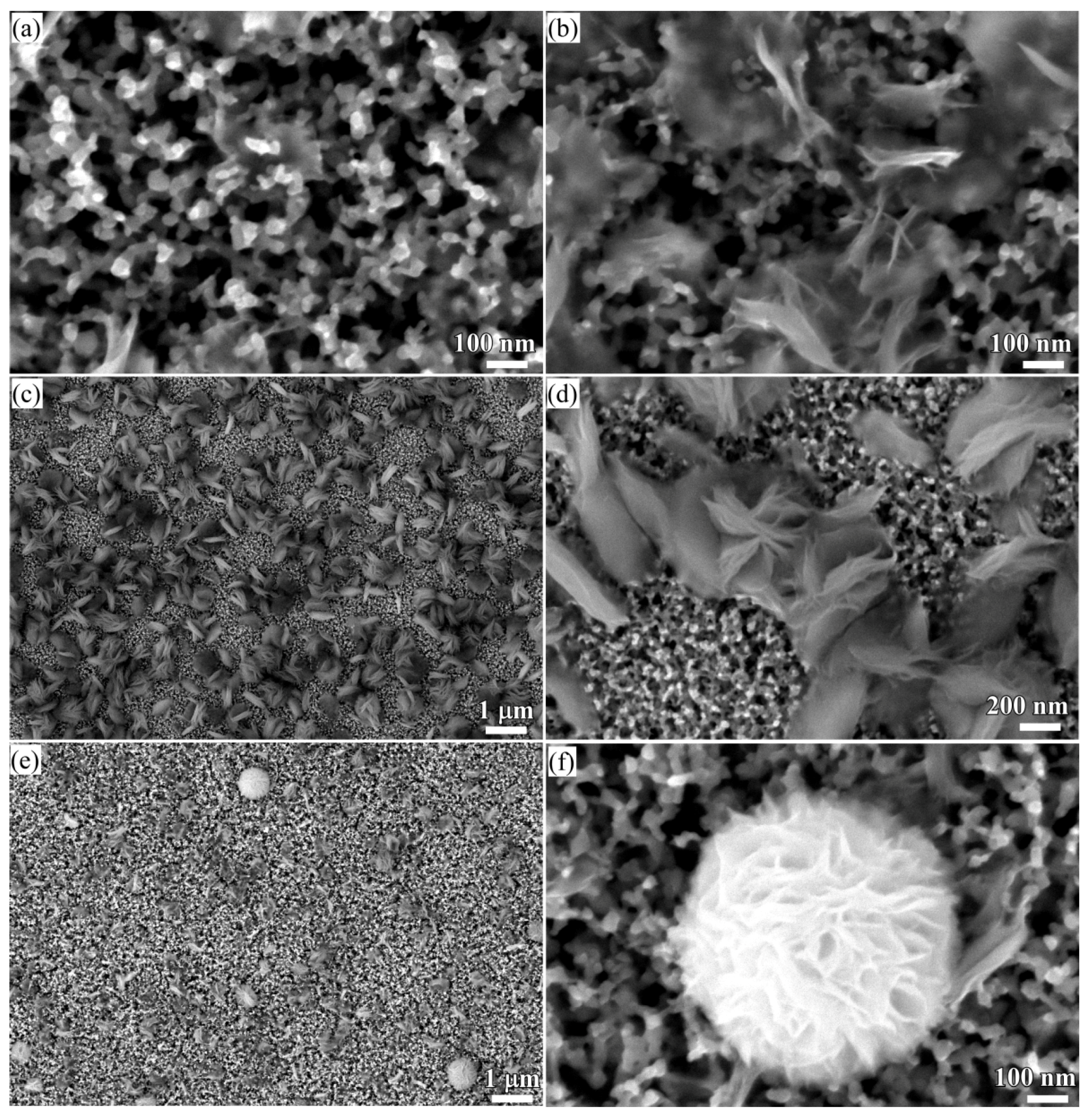
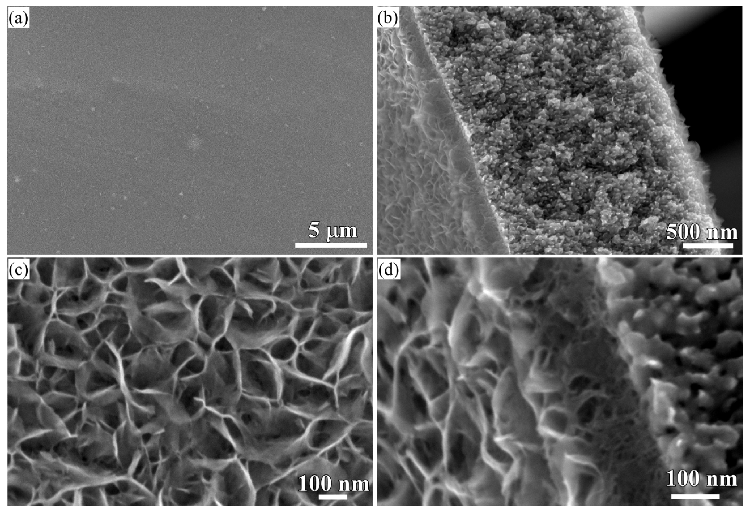
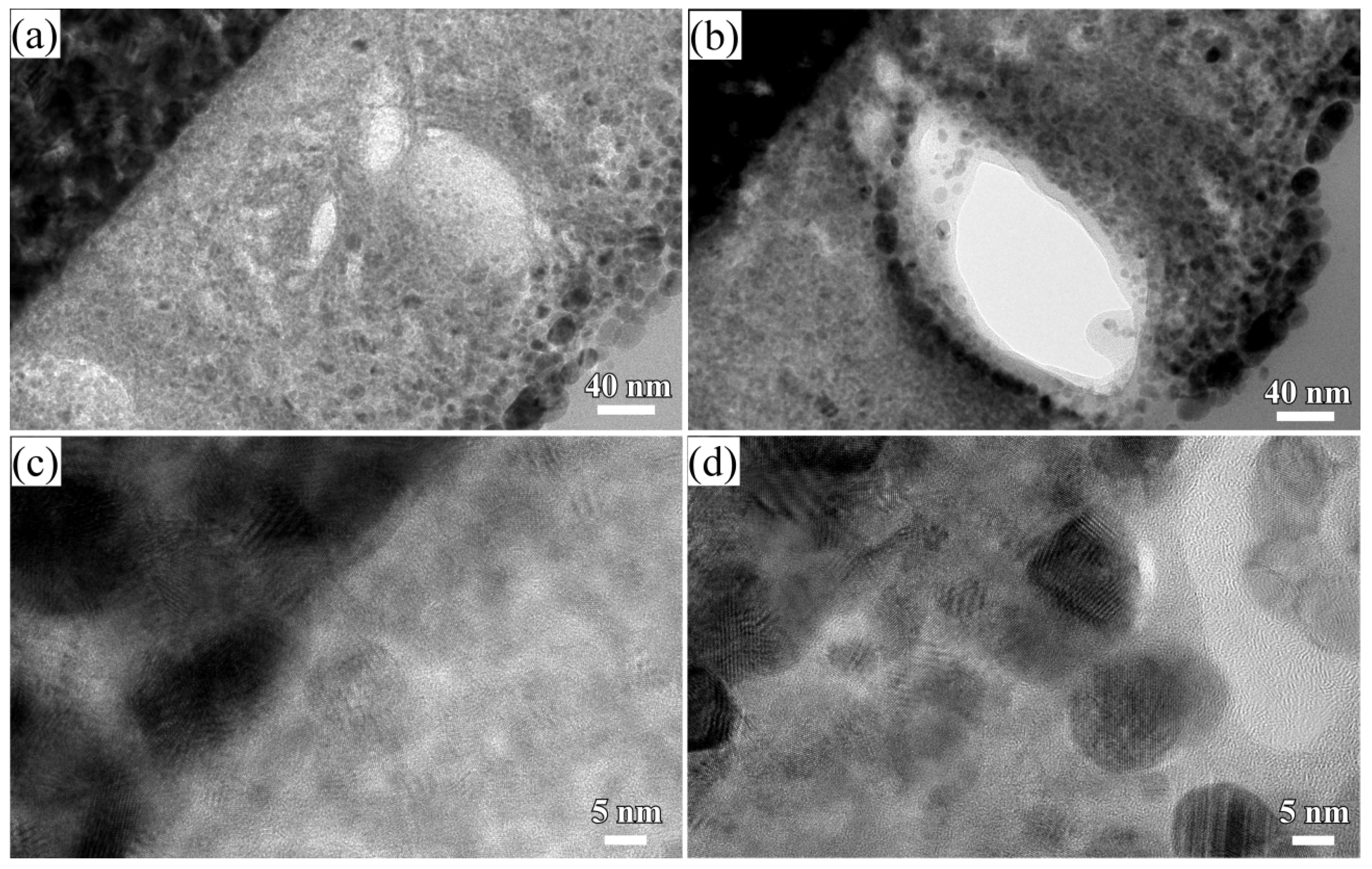
When some factors (dealloying solutions, immersion time, etc.) are changed, the morphology of Cu2O surface nanoarchitectures might be different. The Cu2O nanopetals and their networks were formed on the other NPC templates fabricated in the mixture solution of 0.65 M HF and 0.1 M PVP. The NPC structure with a ligament size of 34 nm and a pore size of 25 nm in the surface region was formed. As shown in Figure 5a, some very thin flakes, so-called nanosheets, formed inside the nanopores after immersion of 5 h in anhydrous ethanol. Some wide nanosheets grew and interlaced together in some regions in Figure 5b. After immersion in anhydrous ethanol for 12 h, more and more nanosheets accumulated to form some flower-like nanostructure (hereafter so-called nanopetals). About 65% surface area was covered by nanopetals in Figure 5c. The XRD pattern of nanopetals (Figure 1b) indicates that the nanopetals consisted of Cu2O phase. On the other hand, the presence of the diffraction peaks from Cu indicated that the surface Cu2O layer was discontinuously distributed. As shown in Figure 5e, the coverage of the Cu2O nanpopetals was less than that in Figure 5c. It is interesting that some Cu2O nanopetals formed China rose shaped structure. Some small nanosheets were also generated inside the nanopores around the large China rose in Figure 5f. After immersion in anhydrous ethanol for 120 h, the surface of NPC templates were fully covered by the nanopetals in Figure 6a. As indicated by XRD patterns in Figure 1c, the diffraction peaks at 29.5°, 36.3°, 42.4° and 61.4° were assigned to Cu2O (110), (111), (200), (220) according to JCPDS card (74-1230). The increase of the intensity and clear splitting of diffraction peaks indicates that the Cu2O phase became the dominant one after immersion of 120 h in anhydrous ethanol and the surface Cu2O layer covered whole surface. The high magnified top-view SEM morphology in Figure 6c shows that the Cu2O nanopetals with very thin thickness interlaced together to form the nanopetals networks. The Cu2O nanopetal network was confirmed to be uniform in thickness along the nanoporous Cu template surface and about 300 nm in the cross-sectional SEM observation in Figure 6b. The morphology of the inner structure in Figure 6b and d shows that no large-sized Cu2O nanoflakes presented in the nanopores or outside of the Cu ligaments. The low-magnified cross-sectional TEM image in Figure 7a shows that the thickness of the surface Cu2O layer was 310 nm. The SADP at Site #1 indicates that the phase of NPC templates is fcc Cu. There are several weak diffraction rings inside the strong diffraction rings of fcc Cu appeared in Figure 7b, which proved that there was small amount of Cu2O phase existed in the nanoporous Cu templates after immersion of 120 h in anhydrous ethanol. The SADP at Site #2 is typical of the patterns of Cu2O surface layer as shown in Figure 7c. The ratio of O/Cu in Figure 7d was close to 0.5, which is the evidence for the chemical composition of Cu2O. The oxygen concentration at the side of NPC templates is not zero indicating the existence of the Cu2O. The cross-sectional TEM morphology in Figure 8a,b shows that the characteristics of the Cu2O nanopetal networks are porous, and many voids and large pores distributed in the surface Cu2O nanopetal networks. Many Cu2O crystals with a size of less than 35 nm distributed outside of the surface layer. The HRTEM images at the interface region of Cu2O/NPC shows that small-sized.
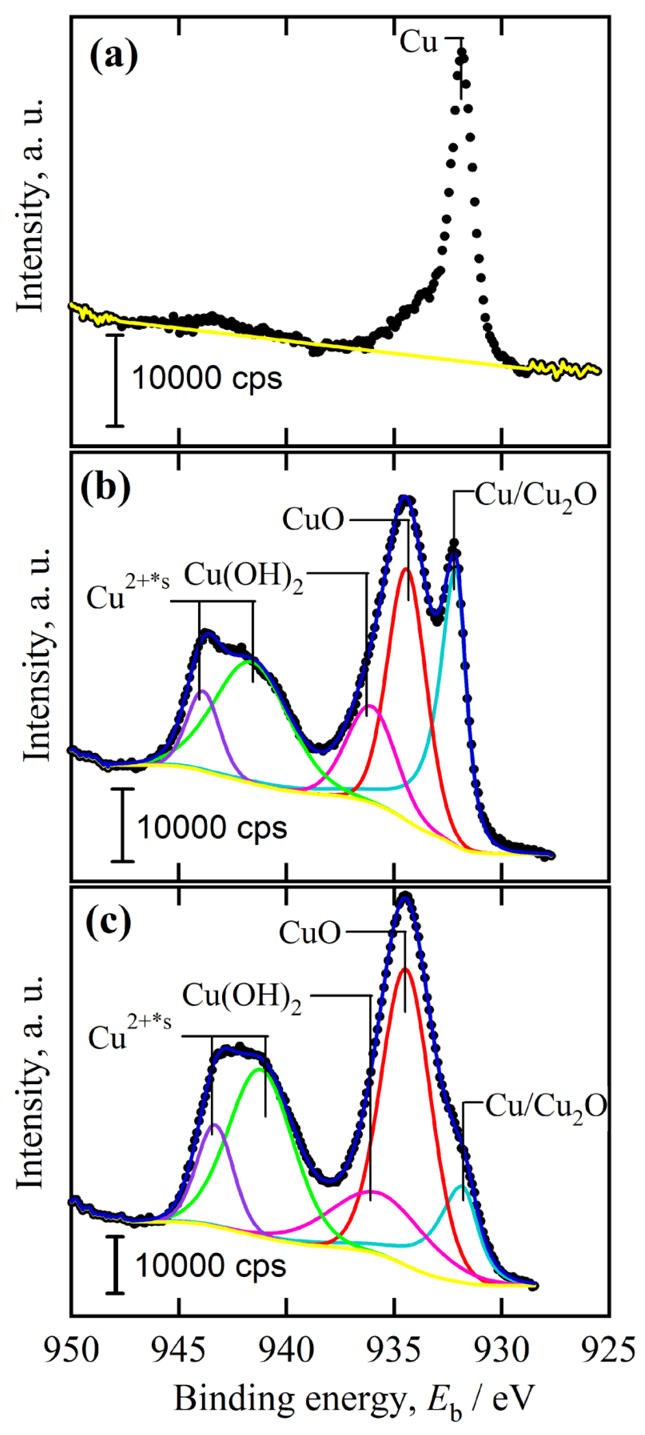
Cu2O particles are very finely crystalline from the regular lattice fringes in Figure 8c. The HRTEM images at the outside region of Cu2O surface layer exhibited that there are many Cu2O crystals with a particle size of about 10–18 nm distributed. The interpanal distance between the adjacent fringes was confirmed to be about 1.83 nm for 10 stacks of the lattice panels, which corresponded to Cu (200). The chemical bonding state of the nanoporous Cu templates, Cu2O nanobelts and Cu2O nanopetal networks after immersion in anhydrous ethanol for 120 h is shown in Figure 9. As shown in Figure 9a, the Cu 2p peak at 931.9 eV was corresponded to the metallic Cu before immersion in ethanol. The Cu2+ has mainly d9 character, while the Cu+ is expected to have a full 3d shell. After nanoporous Cu templates from Ti60Cu40 alloys in a mixture solution of 0.03 M HF and 0.01 M PVP were immersed in anhydrous ethanol for 120 h, the position of Cu/Cu2O peak shifted to 932.2 eV indicating the increase of the Cu2O nanobelts on the surface. The appearance of Cu 2p3/2 peak at 934.4 eV and Cu 2p1/2 peak at 936.1 eV reflects the oxidation state of Cu compounds with localized valence d orbitals due to the different energies of the photoelectrons [38]. The symbol, Cu2+*s, stands for the satellite peaks of Cu 2p. Two shakeup satellite peaks at 941.8 and at 944.1 eV were assigned to bivalent copper. After NPC templates from Ti60Cu40 alloys in a mixture solution of 0.65 M HF and 0.1 M PVP were immersed in anhydrous ethanol for 120 h, the shape of the spectra are similar except the small difference in the intensity. As it is evident from the curve-fitted spectra in Figure 9c, the Cu 2p region shows two peaks at 934.5 and at 935.9 eV assigned to Cu2+ 2p3/2 and 2p1/2, respectively, along with two shakeup satellite peaks at 941.7 and 943.5 eV. These satellite signals are attributed to Cu2+. These subpeak centering at low binding energy of 931.9 eV was attributable to Cu+ species. CuO is considered to be oxidized from the Cu2O species by oxygen in the air. The smaller subpeak of Cu2O is considered to be resulted from the more oxidation of surface Cu2O to form CuO or Cu(OH)2. The Cu(OH)2 species might form as intermediate oxidization products. These species (CuO, Cu(OH)2) are considered to be enriched outside of the Cu ligaments. This hypothesis is established on the basis of the low concentration of CuO and Cu(OH)2 species due to the absence of the diffraction peaks of CuO and Cu(OH)2 in XRD patterns in Figure 1. The present combination of immersion of anhydrous ethanol and finer NPC templates from Ti60Cu40 alloy in the dealloying solution (0.65 M HF + 0.1 M PVP), precursor alloys is considered to be favorable for the formation of the Cu2O nanopetals and nanopetal networks. Meanwhile, the higher concentration of PVP led to the random growth of Cu2O nanostructures on the basis of the data presented in Section 3.1 and Section 3.2. The present combination of dealloying solution (higher PVP and HF concentration) and immersion in anhydrous ethanol led to the formation of the Cu2O layer on NPC templates. The initial microstructure of NPC templates obviously affected the final characteristics of the surface Cu2O products.
3.3. Synergistic Effect of Initial Microstructure of NPC Templates and Stabilizing Agent of Ethanol Molecule on the Shapes of Cu2O Nanostructure
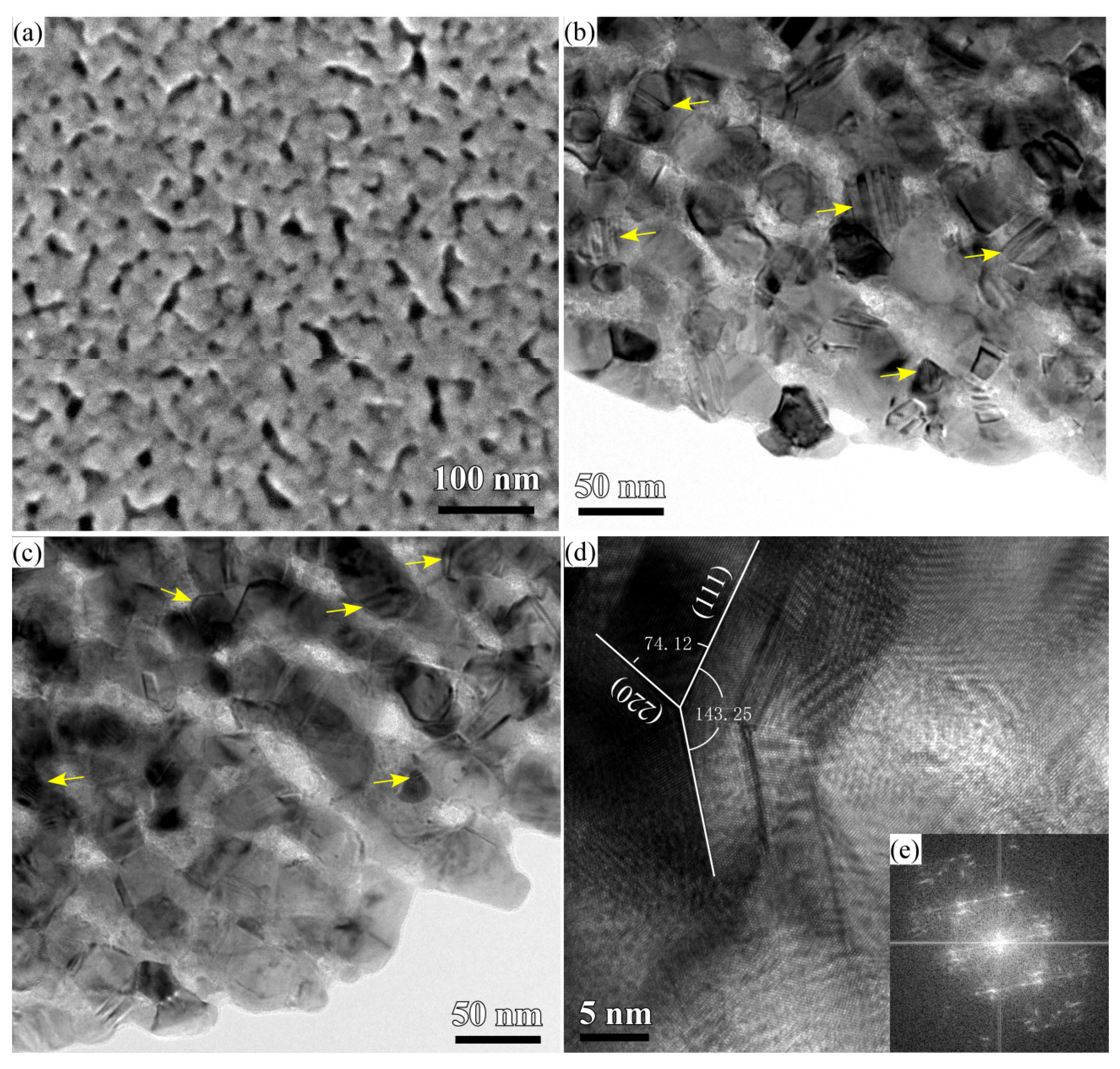
The surface SEM morphology of the nanoporous Cu from Ti60Cu40 alloy in 0.65 M HF and 0.1 M PVP via dealloying in Figure 10a shows that the average pore size was about 8 nm and the average ligament size was about 15 nm. As has been reported, the introduction of PVP into HF solution helps restricting the diffusion and the rearrangement scale of Cu adatoms and reducing the nanopores and ligaments of nanoporous Cu [34]. However, the restricted nucleation and growth of the Cu crystals might cause the increase of the defects, such as twin boundary, stack faults and/or dislocations, etc. Many lamellar defects, stacking faults and other types of defects formed during the dealloying and pileup of the Cu adatoms in Figure 10 b,c. The twin boundary planar defects came from twinning in face-centered cubic structured metallic nanocrystals. HRTEM and fast Fourier transform (FFT) electron diffraction pattern in Figure 10d,e show the dominant features of the lengthwise twins and stacking faults in nanoporous Cu. The distribution density of these kinds of defects was estimated to be 4.20 × 10¹⁷ m−2 for nanoporous Cu dealloyingTi60Cu40 alloy in 0.03 M HF and 0.01 M PVP and 7.18 × 10¹⁷ m−2 for nanoporous Cu dealloyingTi60Cu40 alloy in 0.65 M HF and 0.1 M PVP. The additive PVP concentration and the concentration of HF solution affected the final nanoporous microstructure and the density of the defects. On the other hand, the anhydrous ethanol also played a key role of the formation of the nanobelts and nanopetals. The H2O molecule as reactant helps the formation of Cu2O nanostructures, and ethanol molecule functionalized as a stabilizing or capping reagent for inhibiting the growth of metal nanoparticles [39,40,41]. The ethanol molecule readily adsorb on the Cu surface or Cu2O surface, then form intermediate alkoxy species, and further decomposite to create the reductive environment and finally recombines to recover ethanol molecule. The random growth of Cu2O nanoarchitectures has been suppressed by the preferential adsorption of ethanol molecule [42]. Many defects (i.e., twin boundary and kinks at the edge of ligaments) in the NPC ligaments in Figure 6 and Figure 10 served as initial sites for the ionization. It is believed that the highly localized reduction of the constrained ions might be responsible for the formation of the flat, highly anisotropic shape, like nanosheet or nanopetal shape. The Cu2O compounds preferentially form when solution pH is between 8 and 10, and the alkaline solution enhanced the reduction reaction of cupric (Cu2+) cations to cuprous (Cu+) cations [43,44]. The formation of Cu2O nanostructure obeys the route of Cudefect→ionized Cu+→partial oxidized Cu2+→intermediate Cu(OH)2→preferential reduced Cu+. The formation of the Cu2O nanoarchitectures is affected by curvature of Cu ligaments, the density of defects of nanoporous Cu templates, diffusion of Cu adatoms and Cu+ ions and reactions between Cu+ and active oxygen atoms. Since the ligaments less than 31 nm exhibit saddle point-like features with highly non-uniform values of the mean curvature, the ionized Cu adatoms at the defects is expected to diffuse predominately by local transport on the scale of the ligament length (order of 10 nm) rather than by long-range transport to the outer surface (up to hundreds of microns) [45]. The increase in the defect density and the decrease of nanopores and ligaments in size certainly resulted in the increase of the nucleation sites and the decrease of the diffusion distance for Cu2O nuclei. As shown in the SEM morphology in Figure 2, Figure 5 and Figure 6 and TEM images in Figure 4, Figure 7 and Figure 8, the height of the nanobelts and the thickness of nanopetal networks were almost remain constant after immersion of 24 h similar with the size after 120 h. The nucleation reaction of Cu2O is thus regarded as the rate-determining step. Therefore, the increase of the defect density in NPC templates from Ti60Cu40 alloy in 0.65 M HF and 0.1 M PVP are the most important factor for the formation of the nanopetal networks with increase in the immersion time in anhydrous ethanol. Under the synergistic effect of ethanol molecule and the microstructure of NPC templates, two types of the Cu2O nanoarchitectures (nanobelts and nanopetal networks) finally achieved in the present conditions. The present Cu2O nanoarchitectures with large active surface area, especially nanopetal networks, have great potential for the DNA biosensors of HBV [46], water splitting for mass hydrogen production [47], catalysis for ethanol/methanol production [48], gas sensor of NO2/alcohol/gas oil [49], and lithium ion batteries [50], etc.
4. Conclusions
NPC templates with a pore size of 7.8 and 18 nm have been prepared via dealloying amorphous Ti60Cu40 ribbons in a mixture solution of HF and PVP with different concentrations. Cu2O nanoarchitectures have been fabricated via immersion nanoporous copper templates in anhydrous ethanol. Both water molecule reactant acting as OH− reservoir and the ethanol molecule serving as stabilizing or capping reagent for inhibiting the random growth of Cu2O, played a role of the formation of two dimensional Cu2O nanoarchitectures. Cu2O nanobelts are preferred to form in anhydrous ethanol on the NPC templates from Ti60Cu40 ribbons dealloying in 0.03 M HF and 0.01 M PVP solution, and Cu2O nanopetals are tended to grow in anhydrous ethanol from the NPC templates from Ti60Cu40 ribbons dealloying in 0.65 M HF and 0.1 M PVP solution. With increasing the immersion time in anhydrous ethanol, Cu2O nanopetals united together to create porous networks about 310 nm in thickness. The defect sites (i.e., lamellar defects, twin boundary) on the nanoporous Cu ligaments preferentially tended to serve as nucleation sites for Cu2O nanocrystals. The different shapes of Cu2O nanoarchitectures are affected by the morphology of the initial microstructure of NPC templates, the density of the initial nucleation sites and the solution chemistry of the dealloying solutions.
Acknowledgments
This work is financially supported by the Natural Science Foundation of China under Grant Nos. 51671106, 51401105, Natural Science Foundation of Jiangsu Province under Grants No. BK20171424 and No. BK20151536, and the Natural Science Foundation of the Jiangsu Higher Education Institutions of China under Grant No. 13KJB430015. The authors would also like to acknowledge Jiangsu Collaborative Innovation Center for Advanced Inorganic Function Composites, the International S&T Cooperation Program of China (2015DFA51430) and Priority Academic Program Development of Jiangsu Higher Education Institution (PAPD).
Author Contributions
Z.D. did some works such as Design of the work, Data analysis, Data collection and writing the manuscript; J.L. was in charge of Data collection and preparation of the figures; F.L. did some work of data collection; F.Q. was in charge of sample preparation and data analysis; H.C. was in charge of Design of the work and Data interpretation.
Conflicts of Interest
There are no conflicts of interest between all of authors. There are no conflicts of interest between the involved funds.
References
- Kim, M.H.; Lim, B.; Lee, E.P.; Xia, Y.N. Polyol synthesis of Cu2O nanoparticles: Use of chloride to promote the formation of a cubic morphology. J. Mater. Chem. 2008, 18, 4069–4073. [Google Scholar] [CrossRef]
- Chen, Z.Z.; Shi, E.W.; Zheng, Y.Q.; Li, W.J.; Xiao, B.; Zhuang, J.Y. Growth of hex-pod-like Cu2O whisker under hydrothermal conditions. J. Cryst. Growth 2003, 249, 294–300. [Google Scholar] [CrossRef]
- Xu, H.L.; Wang, W.Z.; Zhu, W. Shape evolution and size-controllable synthesis of Cu2O octahedra and their morphology-dependent photocatalytic properties. J. Phys. Chem. B 2006, 110, 13829–13834. [Google Scholar] [CrossRef] [PubMed]
- Luo, Y.S.; Tu, Y.C.; Ren, Q.F.; Dai, X.J.; Xing, L.L.; Li, J.L. Surfactant-free fabrication of Cu2O nanosheets from Cu colloids and their tunable optical properties. J. Solid State Chem. 2009, 182, 182–186. [Google Scholar] [CrossRef]
- Cao, M.H.; Hu, C.W.; Wang, Y.H.; Guo, Y.H.; Guo, C.X.; Wang, E.B. A controllable synthetic route to Cu, Cu2O, and CuO nanotubes and nanorods. Chem. Commun. 2003, 1884–1885. [Google Scholar] [CrossRef]
- Luo, Y.S.; Li, S.Q.; Ren, Q.F.; Liu, J.P.; Xing, L.L.; Wang, Y.; Yu, Y.; Jia, Z.J.; Li, J.L. Facile synthesis of flowerlike Cu2O nanoarchitectures by a solution phase route. Cryst. Growth Des. 2007, 7, 87–92. [Google Scholar] [CrossRef]
- Xu, C.; Wang, X.; Yang, L.C.; Wu, Y.P. Fabrication of a graphene–cuprous oxide composite. J. Solid State Chem. 2009, 182, 2486–2490. [Google Scholar] [CrossRef]
- Wang, D.B.; Mo, M.S.; Yu, D.B.; Xu, L.Q.; Li, F.Q.; Qian, Y.T. Large-scale growth and shape evolution of Cu2O cubes. Cryst. Growth Des. 2003, 3, 717–720. [Google Scholar] [CrossRef]
- Tan, Y.W.; Xue, X.Y.; Peng, Q.; Zhao, H.; Wang, T.H.; Li, Y.D. Controllable fabrication and electrical performance of single crystalline Cu2O nanowires with high aspect ratios. Nano Lett. 2007, 7, 3723–3728. [Google Scholar] [CrossRef]
- Kuo, C.H.; Chen, C.H.; Huang, M.H. Seed-Mediated synthesis of monodispersed Cu2O nanocubes with five different size ranges from 40 to 420 nm. Adv. Funct. Mater. 2007, 17, 3773–3780. [Google Scholar] [CrossRef]
- Gou, L.F.; Murphy, C.J. Solution-phase synthesis of Cu2O nanocubes. Nano Lett. 2003, 3, 231–234. [Google Scholar] [CrossRef]
- Wiley, B.; Sun, Y.G.; Mayers, B.; Xia, Y.N. Shape-controlled synthesis of metal nanostructures: The case of silver. Chem. Eur. J. 2005, 11, 454–463. [Google Scholar] [CrossRef] [PubMed]
- Xiong, Y.J.; Xia, Y.N. Shape-controlled synthesis of metal nanostructures: The case of palladium. Adv. Mater. 2007, 19, 3385–3391. [Google Scholar] [CrossRef]
- Sun, Y.G.; Xia, Y.N. Mechanistic study on the replacement reaction between silver nanostructures and chloroauric acid in aqueous medium. J. Am. Chem. Soc. 2004, 126, 3892–3901. [Google Scholar] [CrossRef] [PubMed]
- Zhang, H.G.; Zhu, Q.S.; Zhang, Y.; Wang, Y.; Zhao, L.; Yu, B. One-pot synthesis and hierarchical assembly of hollow Cu2O microspheres with nanocrystals-composed porous multishell and their gas-sensing properties. Adv. Funct. Mater. 2007, 17, 2766–2771. [Google Scholar] [CrossRef]
- Xu, J.S.; Xue, D.F. Five branching growth patterns in the cubic crystal system: A direct observation of cuprous oxide microcrystals. Acta Mater. 2007, 55, 2397–2406. [Google Scholar] [CrossRef]
- Chang, Y.; Zeng, H.C. Manipulative synthesis of multipod frameworks for self-organization and self-amplification of Cu2O microcrystals. Cryst. Growth Des. 2004, 4, 273–278. [Google Scholar] [CrossRef]
- Xiong, Y.J.; Li, Z.Q.; Zhang, R.; Xie, Y.; Yang, J.; Wu, C.Z. From complex chains to 1D metal oxides: A novel strategy to Cu2O nanowires. J. Phys. Chem. B 2003, 107, 3697–3702. [Google Scholar] [CrossRef]
- Zhang, X.; Xie, Y.; Xu, F.; Liu, X.H.; Xu, D. Shape-controlled synthesis of submicro-sized cuprous oxide octahedra. Inorg. Chem. Commun. 2003, 6, 1390–1392. [Google Scholar] [CrossRef]
- Zhang, H.W.; Zhang, X.; Li, H.Y.; Qu, Z.K.; Fan, S.; Ji, M.Y. Hierarchical growth of Cu2O double tower-tip-like nanostructures in water/oil microemulsion. Cryst. Growth Des. 2007, 7, 820–824. [Google Scholar] [CrossRef]
- Siegfried, M.J.; Choi, K.S. Electrochemical crystallization of cuprous oxide with systematic shape evolution. Adv. Mater. 2004, 16, 1743–1746. [Google Scholar] [CrossRef]
- Siegfried, M.J.; Choi, K.S. Directing the architecture of cuprous oxide crystals during electrochemical growth. Angew. Chem. Int. Ed. 2005, 44, 3282–3287. [Google Scholar] [CrossRef]
- Siegfried, M.J.; Choi, K.S. Elucidation of an overpotential-limited branching phenomenon observed during the electrocrystallization of cuprous oxide. Angew. Chem. Int. Ed. 2008, 47, 368–372. [Google Scholar] [CrossRef] [PubMed]
- Li, J.; Shi, Y.; Cai, Q.; Sun, Q.Y.; Li, H.D.; Chen, X.H.; Wang, X.P.; Yan, Y.J.; Vireling, E.G. Patterning of nanostructured cuprous oxide by surfactant-assisted electrochemical deposition. Cryst. Growth Des. 2008, 8, 2652–2659. [Google Scholar] [CrossRef]
- Zhang, Z.H.; Wang, Y.; Qi, Z.; Zhang, W.H.; Qin, J.Y.; Frenzel, J. Generalized fabrication of nanoporous metals (Au, Pd, Pt, Ag, and Cu) through chemical dealloying. J. Phys. Chem. C 2009, 113, 12629–12636. [Google Scholar] [CrossRef]
- Erlebacher, J.; Aziz, M.J.; Karma, A.; Dimitrov, N.; Sieradzki, K. Evolution of nanoporosity in dealloying. Nature 2001, 410, 450–453. [Google Scholar] [CrossRef] [PubMed] [Green Version]
- Dan, Z.H.; Qin, F.X.; Wada, T.; Yamaura, S.; Xie, G.Q.; Sugawara, Y.; Muto, I.; Makino, A.; Hara, N. Nanoporous palladium fabricated from an amorphous Pd42.5Cu30Ni7.5P20 precursor and its ethanol electro-oxidation performance. Electrochim. Acta 2013, 108, 512–519. [Google Scholar] [CrossRef]
- Yu, J.S.; Ding, Y.; Xu, C.X.; Inoue, A.; Sakurai, T.; Chen, M.W. Nanoporous metals by dealloying multicomponent metallic glasses. Chem. Mater. 2008, 20, 4548–4550. [Google Scholar] [CrossRef]
- Dan, Z.H.; Qin, F.X.; Sugawara, Y.; Muto, I.; Hara, N. Fabrication of nanoporous copper by dealloying amorphous binary Ti-Cu alloys in hydrofluoric acid solutions. Intermetallics 2012, 9, 14–20. [Google Scholar] [CrossRef]
- Dan, Z.H.; Qin, F.X.; Hara, N. Refinement of nanoporous copper: A summary of micro-alloying of Au-group and Pt-group elements. Mater. Trans. 2014, 55, 796–800. [Google Scholar] [CrossRef]
- Dan, Z.H.; Qin, F.X.; Sugawara, Y.; Muto, I.; Hara, N. Bimodal nanoporous nickel prepared by dealloying Ni38Mn62 alloys. Intermetallics 2012, 31, 157–164. [Google Scholar] [CrossRef]
- Dan, Z.H.; Qin, F.X.; Sugawara, Y.; Muto, I.; Hara, N. Elaboration of nanoporous copper by modifying surface diffusivity by the minor addition of gold. Microporous Mesoporous Mater. 2013, 165, 257–264. [Google Scholar] [CrossRef]
- Dan, Z.H.; Qin, F.X.; Yamaura, S.; Xie, G.Q.; Makino, A.; Hara, N. Refinement of nanoporous copper by dealloying MgCuY amorphous alloys in sulfuric acids containing polyvinylpyrrolidone. J. Electrochem. Soc. 2014, 161, C120–C125. [Google Scholar] [CrossRef]
- Dan, Z.H.; Qin, F.X.; Hara, N. Polyvinylpyrrolidone macromolecules function as a diffusion barrier during dealloying. Mater. Chem. Phys. 2014, 146, 277–282. [Google Scholar] [CrossRef]
- Kou, T.Y.; Jin, C.H.; Zhang, C.; Sun, J.Z.; Zhang, Z.H. Nanoporous core–shell Cu@Cu2O nanocomposites with superior photocatalytic properties towards the degradation of methyl orange. RSC Adv. 2012, 2, 12636–12643. [Google Scholar] [CrossRef]
- Liu, D.Q.; Yang, Z.B.; Wang, P.; Li, F.; Wang, D.S.; He, D.Y. Preparation of 3D nanoporous copper-supported cuprous oxide for high-performance lithium ion battery anodes. Nanoscale 2013, 5, 1917–1921. [Google Scholar] [CrossRef] [PubMed]
- Liu, W.B.; Zhang, S.C.; Li, N.; Zheng, J.W.; Xing, Y.L. A facile one-pot route to fabricate nanoporous copper with controlled hierarchical pore size distributions through chemical dealloying of Al–Cu alloy in an alkaline solution. Microporous Mesoporous Mater. 2011, 138, 1–7. [Google Scholar] [CrossRef]
- Chanquía, C.M.; Sapag, K.; Rodríguez-Castellόn, E.; Herrero, E.R.; Eimer, G.A. Nature and location of copper nanospecies in mesoporous molecular sieves. J. Phys. Chem. C 2010, 114, 1481–1490. [Google Scholar] [CrossRef]
- Li, D.; McCann, J.; Matthew, T.; Xia, Y.N. Photocatalytic deposition of gold nanoparticles on electrospun nanofibers of titania. Chem. Phys. Lett. 2004, 394, 387–391. [Google Scholar] [CrossRef]
- Leff, D.V.; Ohara, P.C.; Heath, J.R.; Gelbart, W.M. Thermodynamic control of gold nanocrystal size: Experiment and theory. J. Phys. Chem. 1995, 99, 7036–7041. [Google Scholar] [CrossRef]
- Wiley, B.J.; Xiong, Y.J.; Li, Z.Y.; Yin, Y.D.; Xia, Y.N. Right bipyramids of silver: A new shape derived from single twinned seeds. Nano Lett. 2006, 6, 765–768. [Google Scholar] [CrossRef] [PubMed]
- Bowker, M.; Madix, R.J. XPS, UPS and thermal desorption studies of alcohol adsorption on Cu(110): II. Higher alcohols. Surf. Sci. 1982, 116, 549–572. [Google Scholar] [CrossRef]
- Ko, E.S.; Choi, J.; Okamoto, K.; Tak, Y.S.; Lee, J.Y. Cu2O nanowires in an alumina template: Electrochemical conditions for the synthesis and photoluminescence characteristics. ChemPhysChem 2006, 7, 1505–1509. [Google Scholar] [CrossRef] [PubMed]
- Choi, J.S.; Ko, E.S.; Kang, J.W.; Tak, Y.S.; Lee, J.Y. Influence of solution pH on the electrochemical fabrication of functional metal oxides using a nanoporous alumina template. J. Ind. Eng. Chem. 2007, 13, 305–309. [Google Scholar]
- Parida, S.; Kramer, D.; Volkert, C.A.; Rosner, H.; Erlebacher, J.; Weissmüller, A. Volume change during the formation of nanoporous gold by dealloying. Phys. Rev. Lett. 2006, 97, 35504. [Google Scholar] [CrossRef] [PubMed]
- Zhu, H.T.; Wang, J.X.; Xu, G.Y. Fast Synthesis of Cu2O Hollow Microspheres and Their Application in DNA Biosensor of Hepatitis B Virus. Cryst. Growth Des. 2009, 9, 633–638. [Google Scholar] [CrossRef]
- Luo, J.S.; Steier, L.; Son, M.K.; Schreier, M.; Mayer, M.T.; Grätzel, M. Cu2O nanowire photocathodes for efficient and durable solar water splitting. Nano Lett. 2016, 16, 1848–1857. [Google Scholar] [CrossRef] [PubMed]
- Christoforidis, K.C.; Fornasiero, P. Photocatalytic hydrogen production: A rift into the future energy supply. ChemCatChem 2017, 9, 1523–1544. [Google Scholar] [CrossRef]
- Zhang, J.T.; Liu, J.F.; Peng, Q.; Wang, X.; Li, Y.D. Nearly monodisperse Cu2O and CuO nanospheres: Preparation and applications for sensitive gas sensors. Chem. Mater. 2006, 18, 867–871. [Google Scholar] [CrossRef]
- Zhang, C.; Tu, J.; Huang, X.; Yuan, Y.; Chen, X.; Mao, F. Preparation and electrochemical performances of cubic shape Cu2O as anode material for lithium ion batteries. J. Alloy. Compd. 2007, 441, 52–56. [Google Scholar] [CrossRef]
Figure 1.
XRD pattern of Ti60Cu40 ribbon dealloyed in 0.03 M HF + 0.01 M PVP solution after immersion of 120 h in anhydrous ethanol (a) and XRD pattern of amorphous Ti60Cu40 ribbons after dealloying in 0.65 M HF + 0.1 M PVP after immersion of 24 h (b) and 120 h in anhydrous ethanol (c).
Figure 1.
XRD pattern of Ti60Cu40 ribbon dealloyed in 0.03 M HF + 0.01 M PVP solution after immersion of 120 h in anhydrous ethanol (a) and XRD pattern of amorphous Ti60Cu40 ribbons after dealloying in 0.65 M HF + 0.1 M PVP after immersion of 24 h (b) and 120 h in anhydrous ethanol (c).
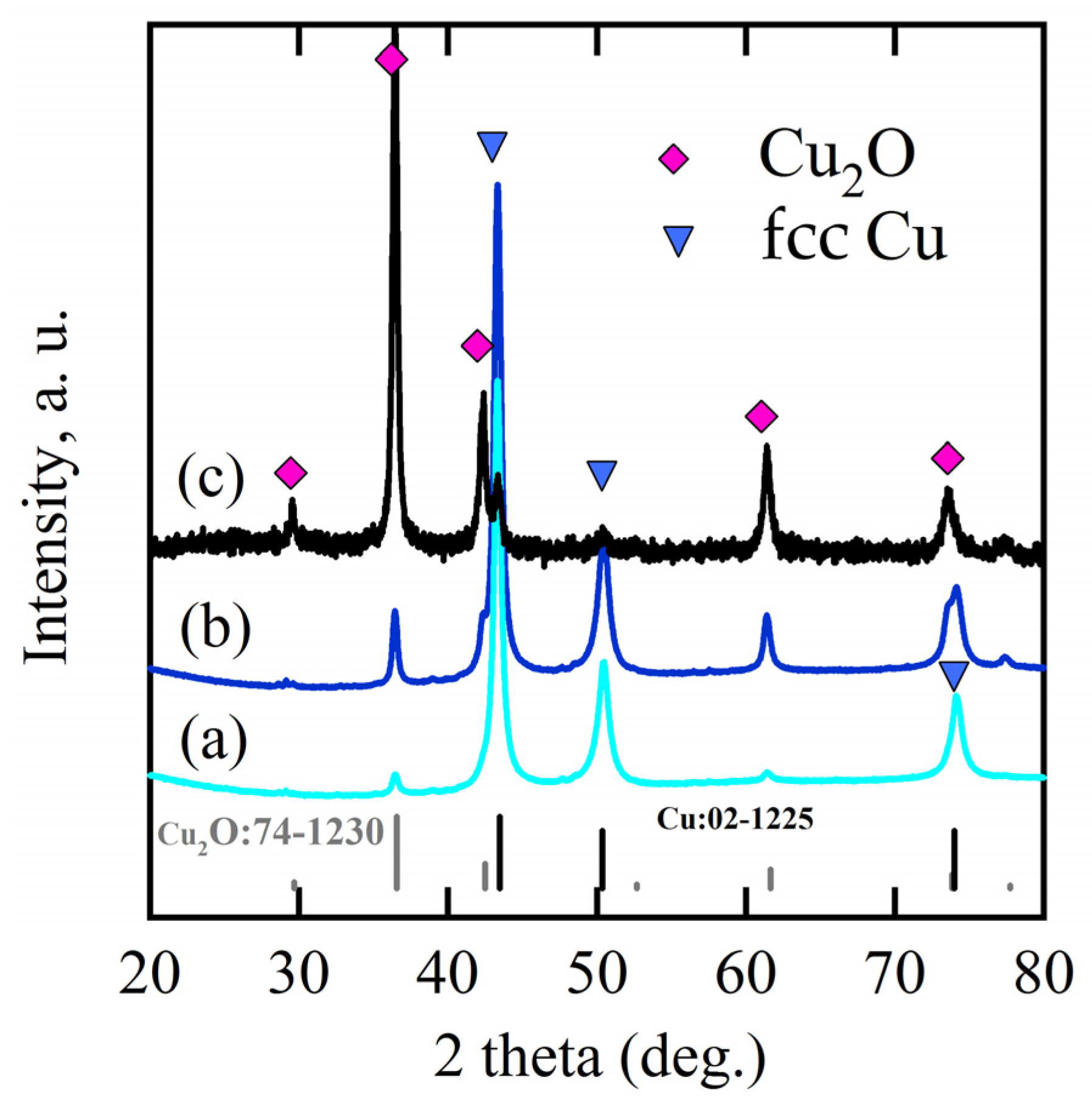
Figure 2.
SEM morphology of Ti60Cu40 ribbon dealloyed in 0.03 M HF + 0.01 M PVP solution after immersion of 120 h in anhydrous ethanol (a) and its magnified images at middle region (b) and the edge region (c).
Figure 2.
SEM morphology of Ti60Cu40 ribbon dealloyed in 0.03 M HF + 0.01 M PVP solution after immersion of 120 h in anhydrous ethanol (a) and its magnified images at middle region (b) and the edge region (c).
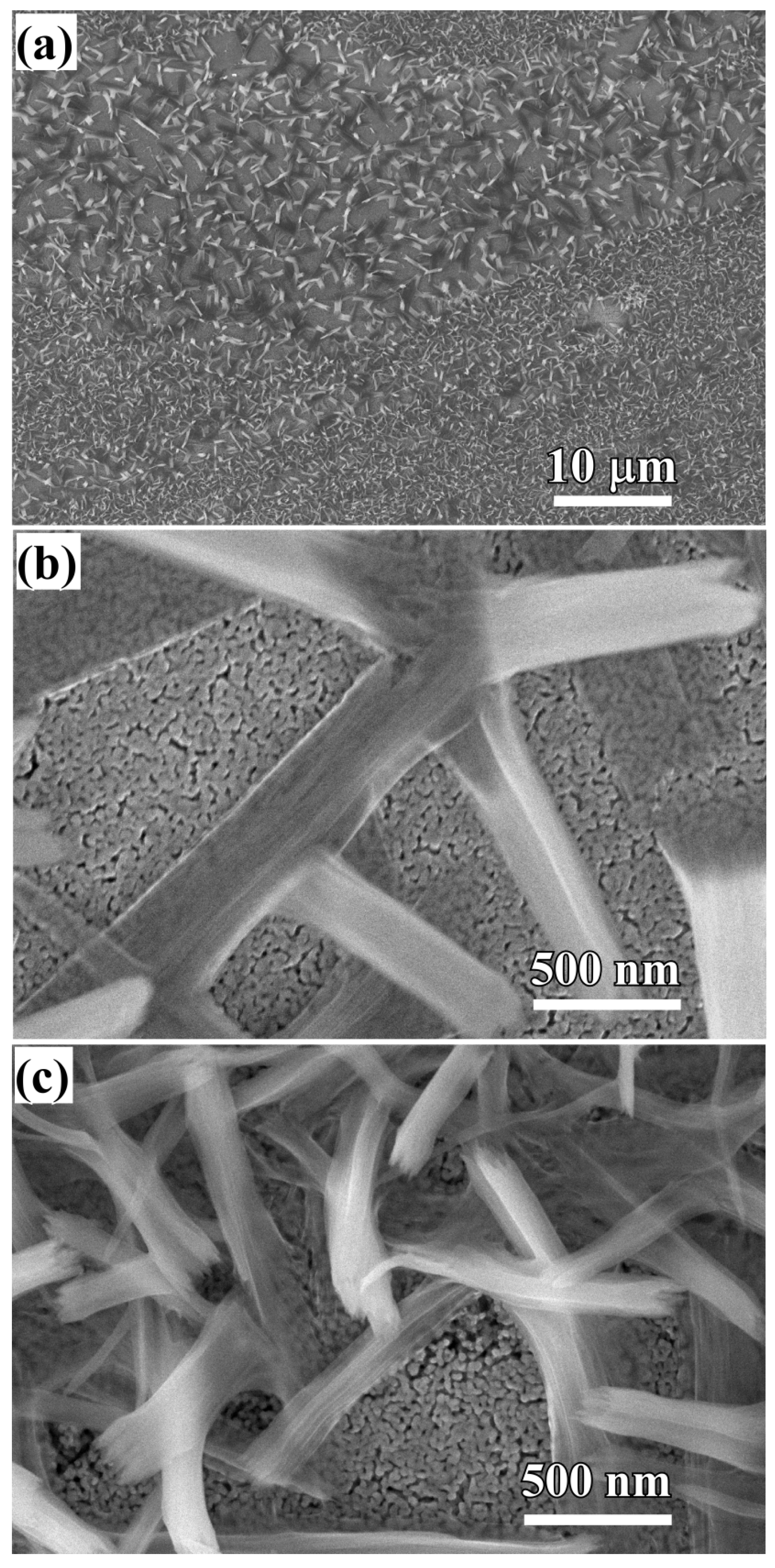
Figure 3.
SEM image (a) and its elemental distribution of O (b) and Cu (c) of Ti60Cu40 ribbon dealloyed in 0.03 M HF + 0.01 M PVP solution after immersion of 120 h in anhydrous ethanol.
Figure 3.
SEM image (a) and its elemental distribution of O (b) and Cu (c) of Ti60Cu40 ribbon dealloyed in 0.03 M HF + 0.01 M PVP solution after immersion of 120 h in anhydrous ethanol.

Figure 4.
Cross-sectional bright field image (a); the magnified image of the root parts of Cu2O nanobelts (b,d) formed on Ti60Cu40 ribbon dealloyed in 0.03 M HF + 0.01 M PVP solution after immersion of 120 h in ethanol and the high-resolution TEM image (c). The inset in b is the SADP.
Figure 4.
Cross-sectional bright field image (a); the magnified image of the root parts of Cu2O nanobelts (b,d) formed on Ti60Cu40 ribbon dealloyed in 0.03 M HF + 0.01 M PVP solution after immersion of 120 h in ethanol and the high-resolution TEM image (c). The inset in b is the SADP.
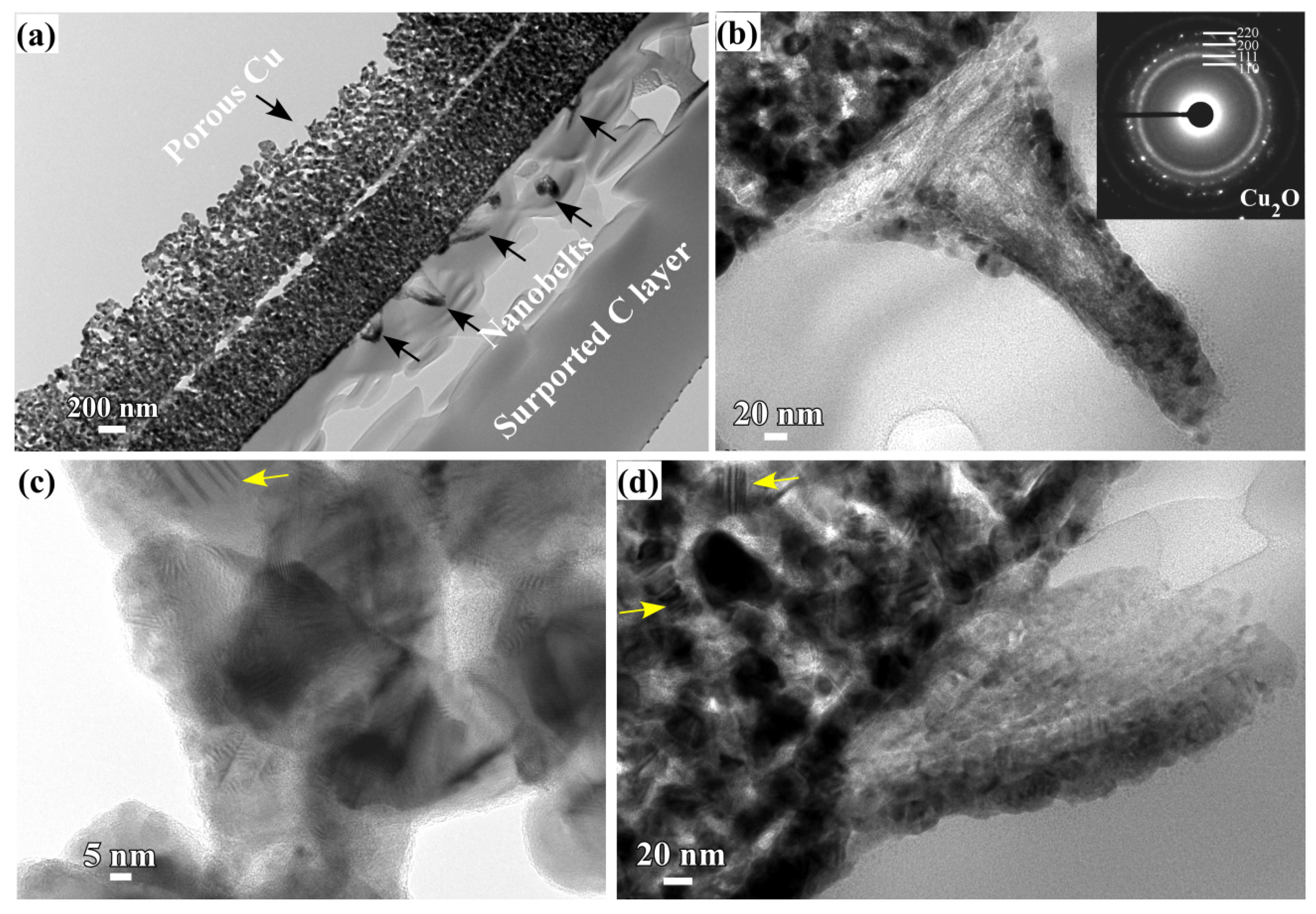
Figure 5.
Low-magnificence SEM morphology of Ti60Cu40 ribbon dealloyed in 0.65 M HF + 0.1 M PVP solution after immersion in anhydrous ethanol for 5 h (a,b); and for 12 h (c,e) and corresponding high-magnificence SEM image (d,f).
Figure 5.
Low-magnificence SEM morphology of Ti60Cu40 ribbon dealloyed in 0.65 M HF + 0.1 M PVP solution after immersion in anhydrous ethanol for 5 h (a,b); and for 12 h (c,e) and corresponding high-magnificence SEM image (d,f).

Figure 6.
Top-view (a) and cross-sectional view (b) low-magnificence SEM morphology and their corresponding high magnificence SEM morphology (c,d) of Ti60Cu40 ribbon dealloyed in 0.65 M HF + 0.1 M PVP solution after immersion of 120 h in anhydrous ethanol.
Figure 6.
Top-view (a) and cross-sectional view (b) low-magnificence SEM morphology and their corresponding high magnificence SEM morphology (c,d) of Ti60Cu40 ribbon dealloyed in 0.65 M HF + 0.1 M PVP solution after immersion of 120 h in anhydrous ethanol.

Figure 7.
Bright-field TEM images of porous Cu2O layer and nanoporous substrate (a); SADPs at their corresponding region (b,c) and the line scan profile (d) of the porous layer formed on Ti60Cu40 ribbon dealloyed in 0.65 M HF + 0.1 M PVP solution after immersion of 120 h in anhydrous ethanol.
Figure 7.
Bright-field TEM images of porous Cu2O layer and nanoporous substrate (a); SADPs at their corresponding region (b,c) and the line scan profile (d) of the porous layer formed on Ti60Cu40 ribbon dealloyed in 0.65 M HF + 0.1 M PVP solution after immersion of 120 h in anhydrous ethanol.
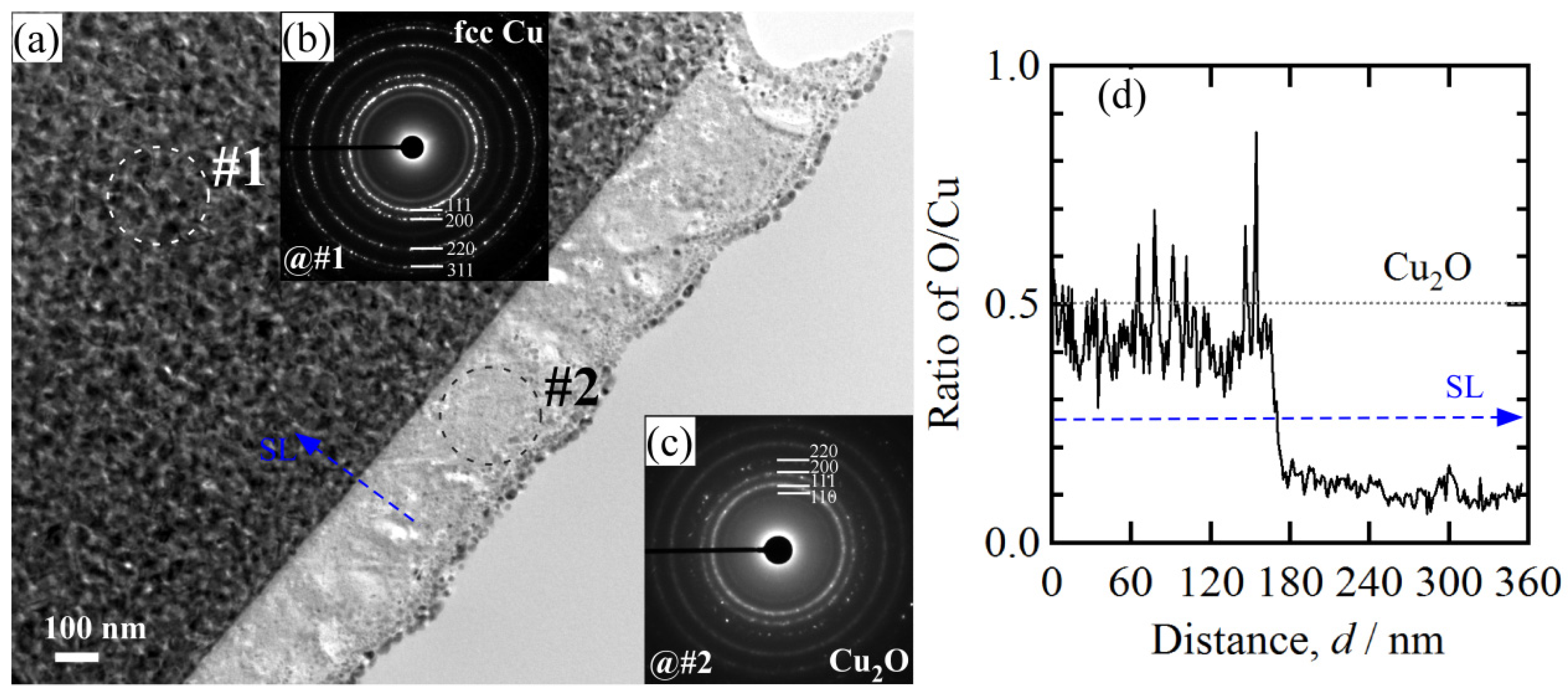
Figure 8.
Cross-sectional bright field TEM image (a,b) at different regions of Cu2O porous layer and high-resolution TEM image at the interfacial zone between porous Cu2O layer and porous substrate (c,d).
Figure 8.
Cross-sectional bright field TEM image (a,b) at different regions of Cu2O porous layer and high-resolution TEM image at the interfacial zone between porous Cu2O layer and porous substrate (c,d).

Figure 9.
XPS spectra of Cu 2p of Ti60Cu40 ribbon after dealloying in 0.03 M HF + 0.01 M PVP solution (a); after immersion of 120 h in anhydrous ethanol (b); XPS spectra of Cu 2p of Ti60Cu40 ribbon dealloyed in 0.65 M HF + 0.1 M PVP solution after immersion of 120 h in anhydrous ethanol (c).
Figure 9.
XPS spectra of Cu 2p of Ti60Cu40 ribbon after dealloying in 0.03 M HF + 0.01 M PVP solution (a); after immersion of 120 h in anhydrous ethanol (b); XPS spectra of Cu 2p of Ti60Cu40 ribbon dealloyed in 0.65 M HF + 0.1 M PVP solution after immersion of 120 h in anhydrous ethanol (c).

Figure 10.
SEM morphology (a);TEM BFI image of nanoporous copper fabricated from Ti60Cu40 ribbon dealloyed in 0.65 M HF + 0.1 M PVP solution (b,c); the high-resolution TEM image at the site where the twin boundaries exists (d) and corresponding FFT pattern (e).
Figure 10.
SEM morphology (a);TEM BFI image of nanoporous copper fabricated from Ti60Cu40 ribbon dealloyed in 0.65 M HF + 0.1 M PVP solution (b,c); the high-resolution TEM image at the site where the twin boundaries exists (d) and corresponding FFT pattern (e).
© 2017 by the authors. Licensee MDPI, Basel, Switzerland. This article is an open access article distributed under the terms and conditions of the Creative Commons Attribution (CC BY) license (http://creativecommons.org/licenses/by/4.0/).
Share and Cite
MDPI and ACS Style
Dan, Z.; Lu, J.; Li, F.; Qin, F.; Chang, H. Ethanol-Mediated 2D Growth of Cu2O Nanoarchitectures on Nanoporous Cu Templates in Anhydrous Ethanol. Nanomaterials 2018, 8, 18. https://doi.org/10.3390/nano8010018
AMA Style
Dan Z, Lu J, Li F, Qin F, Chang H. Ethanol-Mediated 2D Growth of Cu2O Nanoarchitectures on Nanoporous Cu Templates in Anhydrous Ethanol. Nanomaterials. 2018; 8(1):18. https://doi.org/10.3390/nano8010018
Chicago/Turabian StyleDan, Zhenhua, Jiafei Lu, Feng Li, Fengxiang Qin, and Hui Chang. 2018. "Ethanol-Mediated 2D Growth of Cu2O Nanoarchitectures on Nanoporous Cu Templates in Anhydrous Ethanol" Nanomaterials 8, no. 1: 18. https://doi.org/10.3390/nano8010018
Note that from the first issue of 2016, this journal uses article numbers instead of page numbers. See further details here.