Piezoelectric Response of Aligned Electrospun Polyvinylidene Fluoride/Carbon Nanotube Nanofibrous Membranes


Department of Materials Science and Engineering, National Taiwan University of Science and Technology, Taipei 10607, Taiwan, ROC
*
Author to whom correspondence should be addressed.
Nanomaterials 2018, 8(6), 420; https://doi.org/10.3390/nano8060420
Submission received: 26 May 2018
/
Revised: 7 June 2018
/
Accepted: 8 June 2018
/
Published: 10 June 2018
(This article belongs to the Special Issue Smart Nanogenerators)
Abstract
:Polyvinylidene fluoride (PVDF) shows piezoelectricity related to its β-phase content and mechanical and electrical properties influenced by its morphology and crystallinity. Electrospinning (ES) can produce ultrafine and well-aligned PVDF nanofibers. In this study, the effects of the presence of carbon nanotubes (CNT) and optimized ES parameters on the crystal structures and piezoelectric properties of aligned PVDF/CNT nanofibrous membranes were examined. The optimal β content and piezoelectric coefficient (d33) of the aligned electrospun PVDF reached 88% and 27.4 pC/N; CNT addition increased the β-phase content to 89% and d33 to 31.3 pC/N. The output voltages of piezoelectric units with aligned electrospun PVDF/CNT membranes increased linearly with applied loading and showed good stability during cyclic dynamic compression and tension. The sensitivities of the piezoelectric units with the membranes under dynamic compression and tension were 2.26 mV/N and 4.29 mV/%, respectively. In bending tests, the output voltage increased nonlinearly with bending angle because complicated forces were involved. The output of the aligned membrane-based piezoelectric unit with CNT was 1.89 V at the bending angle of 100°. The high electric outputs indicate that the aligned electrospun PVDF/CNT membranes are potentially effective for flexible wearable sensor application with high sensitivity.

1. Introduction
With different demands from many consumers and advancing technology, smart textiles and portable electronic devices that sense human motion and environmental changes have become important research topics. Past wearable sensors in textile garments and accessories were rigid, mainly achieved using traditional inorganic electronic devices. Inorganic materials are stiff materials and electronic devices are typically rigid, inappropriate for textile applications, as they do not provide comfort, durability, low energy consumption, or the ability to stretch or bend. As a result, much research has been devoted to the development of low-cost, flexible, and lightweight sensors with high sensitivities and quick dynamic responses.
Among different piezoelectric materials, polyvinylidene fluoride (PVDF) has been widely studied because it offers conformability that facilitates its application in complex structures. PVDF has five crystalline phases [1]. Among the five polymorphs, the α phase is nonpolar and commonly found in commercial PVDF films. The β phase is polar; in this phase, the dipole moments are oriented in the same direction, thus providing the piezoelectric, pyroelectric, and ferroelectric properties of PVDF and exhibiting the highest electroactive properties [2]. The polar β phase can be obtained through various pretreatments, such as mechanical stretching and high-electric-field poling [3]. The blending of PVDF with iron-based nanomaterials and conductive additives is the most common way to obtain the β phase and improve the electrical properties [4,5,6,7,8,9].
The enhancement of the β phase in solution-cast films of PVDF and PVDF-based copolymers through blending with carbon nanotubes (CNT) was first reported by Carroll’s group [10]. CNT have become widely used because they offer high aspect ratios and electron-rich large surface areas and are thus ideal for chemical functionalizing and the embedding of electromechanical and electrochemical sensing transduction mechanisms within composite film structures. PVDF/CNT composites with well-dispersed CNT exhibited remarkably improved ferro-, pyro-, and piezoelectric properties [11,12,13]. Nanocomposites composed of PVDF and CNT may potentially act as smart materials because of the combination of the piezoelectricity of PVDF, the conductivity of CNT, and the high levels of β-phase formation in electrospun nanofibers. Interfacial polarization occurs in electrically heterogeneous materials [14], that is, composites of materials with different conductivities, such as CNT-polymer composites. Mobile charges within the conductive phase can facilitate composite polarization. Therefore, interfacial polarization increases the dielectric constant of the material [15,16,17].
Electrospinning (ES) is a promising manufacturing technique that forms continuous fibers from polymer solutions or melts under strong electrostatic fields. It can produce fibers with submicrometer-scale diameters through the action of electrostatic forces. In our previous work [18], commercial PVDF film with no treatment possessed only 14% β phase; PVDF film treated by mechanical stretching (stretching ratio = 3.5) showed an increased β phase content of 52%; and PVDF nanofibrous membranes prepared by ES possessed a much higher β phase content of 83%. The results showed that mechanical stretching could induce PVDF crystal arrangement in the polarization structure (β phase), and that the mechanical stretching and electrical poling provided simultaneously in ES could further polarize the crystal structure into the β phase.
Apart from the predominant parameters of precursor solution preparation and applied electric field, different collector types used in ES can affect the morphologies of the electrospun membranes. Electrospun fibrous membranes collected on a fixed collector screen are randomly oriented [19]. Wang and his co-workers used a rotating drum collector in ES to produce PVDF nanofibrous membranes [20]. They compared the electrospun PVDF fibrous membranes obtained under different drum rotation speeds and reported that the alignment of the PVDF nanofibers was significantly affected by the rotation speed of the drum collector. High rotation speeds provided enhanced mechanical drawing on the PVDF fibers, thus increasing the β phase content.
In piezoelectric materials, the piezoelectric performance can be examined by applying stresses or strains and measuring and analyzing the electric outputs of the piezoelectric materials. Wang et al. designed a piezoelectric PVDF unit [21]. The randomly oriented electrospun PVDF nanofibrous membrane was sandwiched between flexible indium tin oxide (ITO) electrodes. Then, the prepared piezoelectric PVDF unit was subjected to a load between 3 and 5 N to observe its piezoelectric response. Among the piezoelectric units with PVDF nanofibers prepared with varied ES parameters, the optimal piezoelectric output under the applied loading reached 140 mV. Liu et al. collected aligned PVDF nanofibers as nonwoven fiber fabric (NFF) on a rotating drum and placed the fibers on a polyethylene terephthalate (PET) substrate with both ends tightly bonded to two copper foil electrodes using silver paste [22]. To obtain better protection between the NFF and electrodes, a thin flexible polymer layer was used to package the entire structure. Under the applied loading frequency of 7 Hz, the generated average peak voltage output value of the prepared piezoelectric unit was 76 mV. Another aligned electrospun PVDF nanofiber mat was incorporated into a piezoelectric unit by Yu et al. [23]. The PVDF-based piezoelectric unit contained two outermost polydimethylsiloxane (PDMS) layers, two aluminum electrodes and a PVDF fibrous mat in center. The piezoelectricity of the fiber mats was measured through a pressure sensor in a home-made testing system. In the applied gas pressure range between 0.145 MPa and 0.165 MPa, the piezoelectric unit exhibited a sensitivity of 178 mV/kPa.
In the aforementioned research on the piezoelectric performance of electrospun PVDF fibrous membranes, the application directions of mechanical forces to the PVDF samples were similar. Whether the force was compression, vibration, or gas pressure, all were applied vertically to the PVDF samples. However, materials do not require flexibility if external forces are only applied vertically. The flexibility of PVDF cannot be observed in the piezoelectric measurements of the above studies. In addition, examining the practical energy conversion abilities of the piezoelectric units, purely vertical forces in nature or in the surrounding environment are rare. Considering human motion as an example, compressive forces occur underneath the foot while walking; muscles experience tensile force while stretching; and bending forces apply at the joints, such as the knees, while walking and jumping.
Therefore, in this study, PVDF fibrous membranes were prepared through ES as three sample types of randomly oriented PVDF fiber mat, well-aligned PVDF fiber mat, and well-aligned PVDF fiber mat with added CNT. The influence of the rotating collector and conductive additives on the β phase content and piezoelectricity of PVDF were investigated. To characterize the piezoelectric performance, the PVDF samples were tested under common mechanical forces: compressive, tensile, and flexural (bending). Finally, the piezoelectric output results were analyzed and compared. These are the highlights of the research in the present work.
2. Results and Discussion
2.1. Morphology of Electrospun Nanofibrous Membranes
Figure 1 represents the morphologies of the three sample types optimized by adjusting the ES parameters. Figure 1a is the scanning electron microscopy (SEM) image of the randomly oriented electrospun PVDF sample, which has the average fiber diameter of 155 ± 17 nm. Figure 1b,c shows the SEM images of the aligned electrospun PVDF without and with CNT with average fiber diameters of 118 ± 23 and 116 ± 21 nm, respectively. Thinner nanofibers are obtained using the rotating drum. A transmission electron microscopy (TEM) image of the aligned electrospun PVDF/CNT nanofibrous membrane is shown in Figure 1d. It is evident that individual CNT are well dispersed in the PVDF nanofibers. Most CNT are embedded within the PVDF nanofibers and oriented along the fiber axes without entangled CNT bundles. Thus, ultrafine electrospun PVDF nanofibrous membranes featuring high surface areas are successfully prepared both with and without CNT. To quantify the alignment of the fibers in each electrospun PVDF sample, the fiber alignment was determined by measuring the degrees of deviation between fibers. The fiber alignments of the randomly oriented electrospun PVDF, aligned electrospun PVDF, and PVDF/CNT are 73° ± 41°, 4.3° ± 7.4°, and 6.1° ± 8.3°, respectively. By comparing the results, it can be clearly understood that a lower fiber deviation angle indicated better fiber alignment, which is further improved by using the rotating collector. However, the addition of CNT did not affect or alter the membrane morphology.
2.2. Crystallinity of Electrospun Nanofiber Membranes
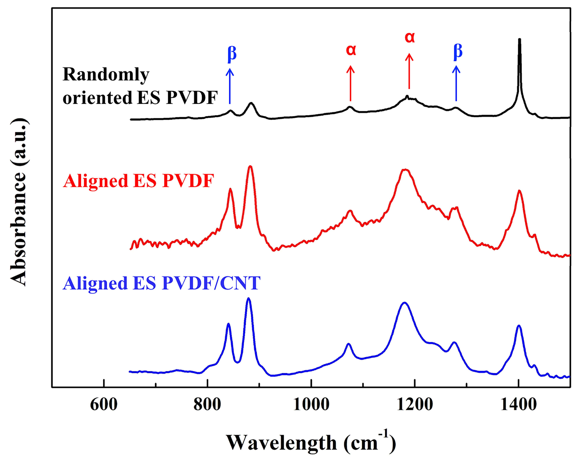
To quantify the variation of the PVDF crystal phases, Fourier-transform infrared (FTIR) spectroscopy was used in this study. Figure 2 shows the FTIR spectra for the randomly oriented electrospun PVDF, aligned electrospun PVDF, and PVDF/CNT, respectively. The α phase is indicated by the bands at 765, 795, and 975 cm−1, and the β phase by those at 840 and 1278 cm−1 [15]. As expected, clear β phases are observed in the aligned electrospun PVDF and PVDF/CNT samples. The relative β-phase fractions of the PVDF samples, F(β), are estimated through the FTIR spectra; the absorption is assumed to follow the Lambert–Beer law [15], and F(β) is calculated using Equation (1):
where Aα and Aβ are the ratios of incident and absorbed intensity at 765 and 840 cm−1, respectively. Kα and Kβ are the absorption coefficients at the respective wavenumber, and Xα and Xβ the degree of crystallinity of each phase. The value of Kα is 6.1 × 104 cm2/mol and Kβ is 7.7 × 104 cm2/mol. Thus, the constant factor 1.3 is obtained from the absorption coefficient rate Kβ/Kα at the corresponding wave number.
The values of F(β) for the PVDF samples are shown in Table 1. The randomly oriented electrospun PVDF collected on a fixed copper grid has 79% β phase. By adjusting the electric field and the rotation speed of the rotating drum, the β phase of the aligned electrospun PVDF reaches 88%. Moreover, the aligned PVDF nanofibrous membranes with CNT show a further increased β phase content of 89%. Therefore, by using the rotating collector in ES, β phase formation is effectively and significantly induced. Thus, CNT addition induces charge accumulation at the material boundary, facilitating the arrangement of PVDF chains in the β-phase conformation [11].
Reinforcements commonly affect polymer crystallization by: (i) acting as nucleation sites for polymer crystallization; and (ii) the immobilization of polymer chains. These effects are intrinsically in opposition, because nucleation increases the crystallinity while chain immobilization delays the crystallization process [24]. Thus, the crystallinity may be influenced by the addition of CNT.
2.3. Piezoelectric Properties of Electrospun Nanofibrous Membranes
Measurements of the piezoelectric coefficient (d33) were used to examine the relationship between the crystallization and piezoelectricity. Table 1 lists the d33 values of the PVDF samples. The d33 values of randomly oriented electrospun PVDF, aligned electrospun PVDF, and PVDF/CNT are 16.8 pC/N, 27.4 pC/N, and 31.3 pC/N, respectively. The d33 value of aligned electrospun PVDF is approximately 1.6 times higher than that of randomly oriented PVDF nanofibrous membranes. Therefore, the mechanical stretching provided by the rotating collector facilitates the crystallization of the β phase and the piezoelectric coefficient is increased with the F(β) value. Although the β phase fraction is only slightly improved in the aligned electrospun PVDF/CNT, this sample exhibits a higher piezoelectric coefficient. The poor enhancement of crystallinity may cause a low dielectric constant. However, the results show that the piezoelectric coefficient of the aligned electrospun PVDF/CNT is higher. The polarization can be enhanced by adjusting the permittivity or dielectric constant of the piezoelectric PVDF polymer by incorporating a conductive phase within the nanofibers [17].
2.4. Mechanical Properties of Electrospun Nanofibrous Membranes
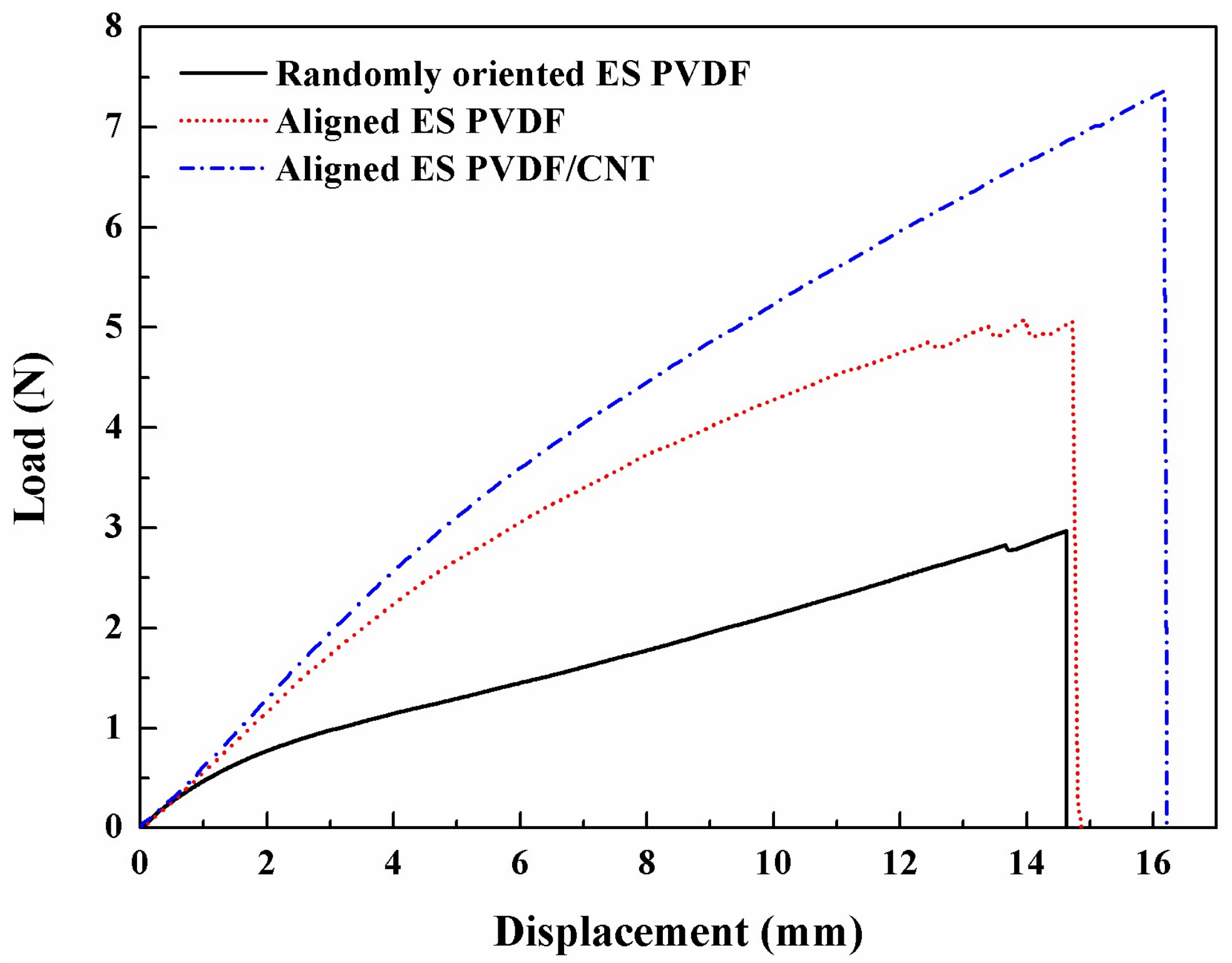
The representative tensile load-displacement curves of the randomly oriented electrospun PVDF, aligned electrospun PVDF, and PVDF/CNT nanofibrous membranes are shown in Figure 3. The load-displacement curves of the three fiber membranes display significant yielding because of the de-entanglement of the nanofibrous webs with applied force. The average tensile strengths of the three PVDF samples are 2.9 N, 5.1 N, and 7.4 N, respectively. The significant improvement is due to the increase in the degree of fiber alignment. When the fibers are oriented in the loading direction, the uniaxial orientation of the fibers helps to distribute the tensile force equally among all fibers [19]. After CNT incorporation, the tensile strength is further increased. The increase in the tensile strength is attributed to the alterations in the polymer microstructure produced through ES and poling [17] and the presence of high-tenacity CNT that are well incorporated within the PVDF nanofibers. Furthermore, the mechanical properties of the aligned electrospun PVDF/CNT are drastically improved; these specimens show higher elongation at break. This is mainly attributed to the physical interaction between the polymer chains and CNT, which may reinforce the electrospun fibers.
2.5. Piezoelectric Responses of Electrospun Nanofibrous Membranes
2.5.1. Piezoelectric Responses under Dynamic Compression
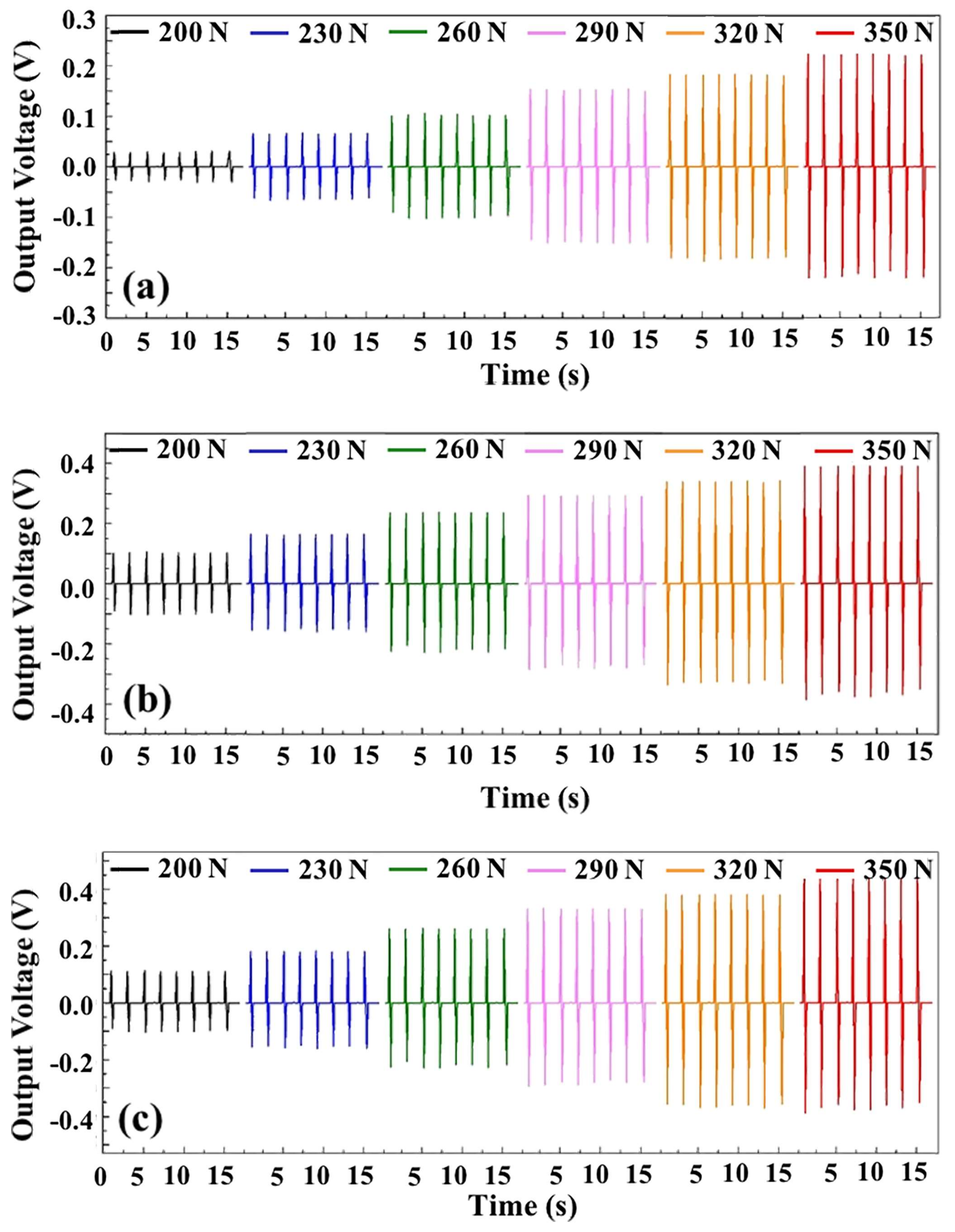
For the compression test, the PVDF samples were cut into circular shapes with diameters of 4 cm. To form piezoelectric units, the samples were simply sandwiched between two copper foils as electrodes with two polypropylene (PP) films placed on the top and the bottom of each unit. The prepared piezoelectric units with randomly oriented electrospun PVDF, aligned electrospun PVDF, and PVDF/CNT were then compressed between two stainless steel cylinders of 3 cm in diameter by a material testing system. The piezoelectric units were assessed under the same compression conditions. Firstly, a prestressing force of 8 N was applied to ensure close contact between adjacent layers of the units. Compressive forces were then applied to the piezoelectric unit at the frequency of 0.5 Hz from 200 N to 350 N. The piezoelectric responses were measured by a source meter unit (SMU) and the results are shown in Figure 4.
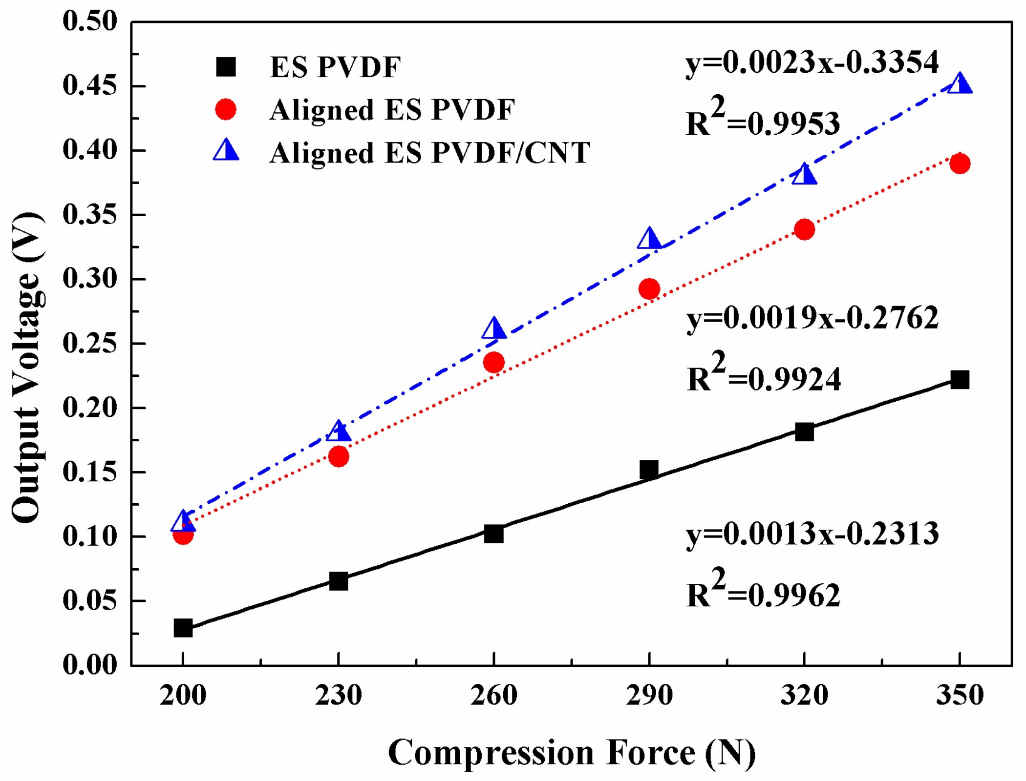
To compare the output voltages of the piezoelectric PVDF units, the values of the output voltages under varied compressive forces were averaged as shown in Figure 5. The results show that the output voltage values of the units containing aligned electrospun PVDF are almost twice those from units with randomly oriented electrospun PVDF. The addition of CNT further improves the piezoelectric properties; the output voltages are even higher than those obtained from units with aligned electrospun PVDF. The sensitivities of the piezoelectric PVDF units with randomly oriented electrospun PVDF, aligned electrospun PVDF, and PVDF/CNT are 1.30 mV/N, 1.93 mV/N, and 2.26 mV/N, respectively. The results indicate that the three PVDF samples show excellent sensitivities.
2.5.2. Piezoelectric Responses under Dynamic Tension
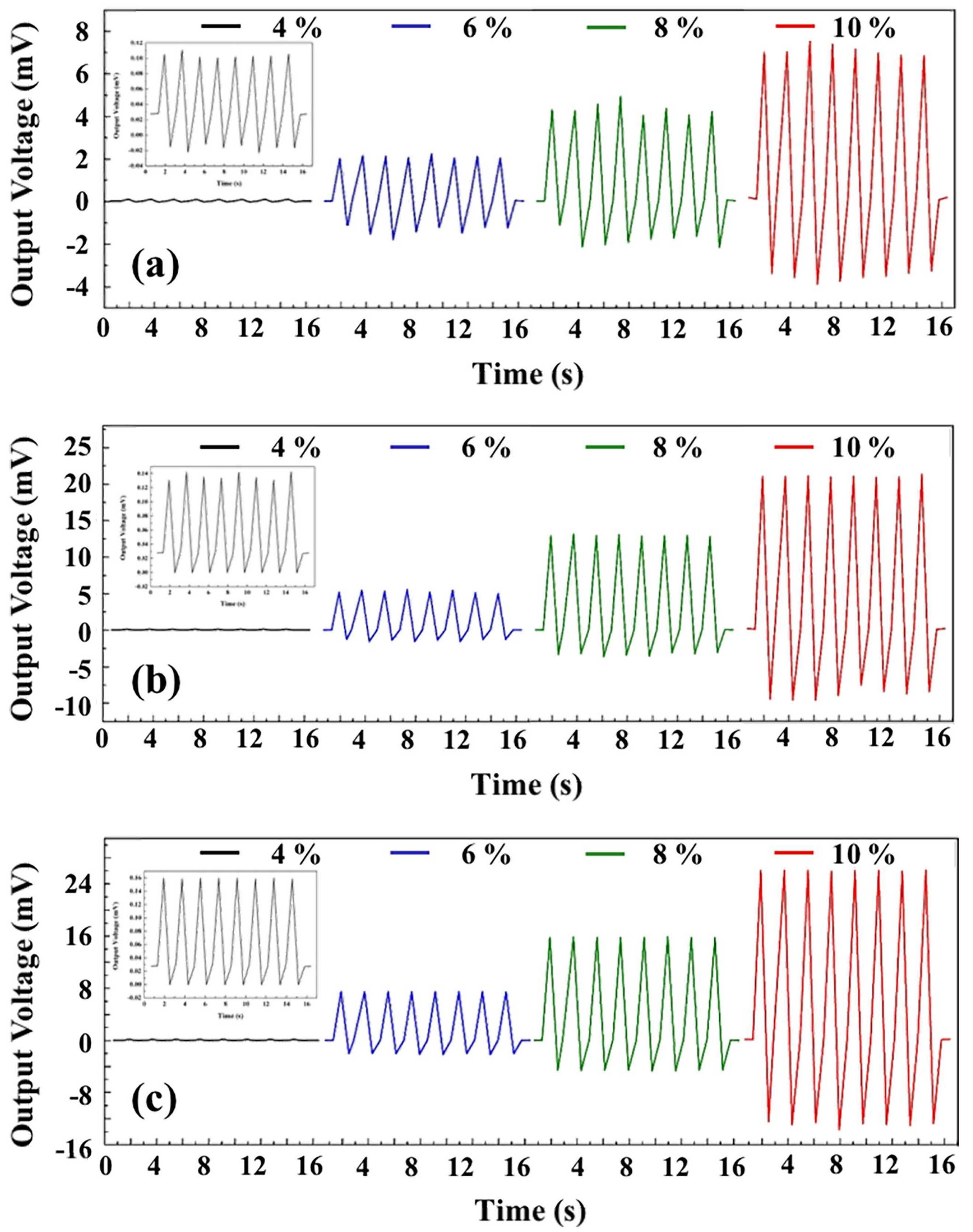
For tensile testing, the PVDF samples were cut to 3 × 3 cm2. To keep the flexibility of the PVDF samples, elastomeric nonwoven material was coated with gold for use as the electrodes. The samples were sandwiched between layers of the gold-coated elastomeric nonwoven. During the tensile tests, the prepared piezoelectric units with PVDF samples were subjected to strain by a universal testing machine. Based on the mechanical properties results from Section 2.4, the yield points of the PVDF samples are observed as ~12% strain. Therefore, the piezoelectric PVDF units were evaluated under 4–10% strain at the frequency of 1 Hz. The piezoelectric responses are shown in Figure 6. The values of the output response curves depend on the applied strain. The electrical signals are stable and repeatable. Furthermore, when more than 8% strain is applied to the randomly oriented electrospun PVDF, the response signal becomes unstable. This is because the strain yielding point is <7% for this PVDF membrane.
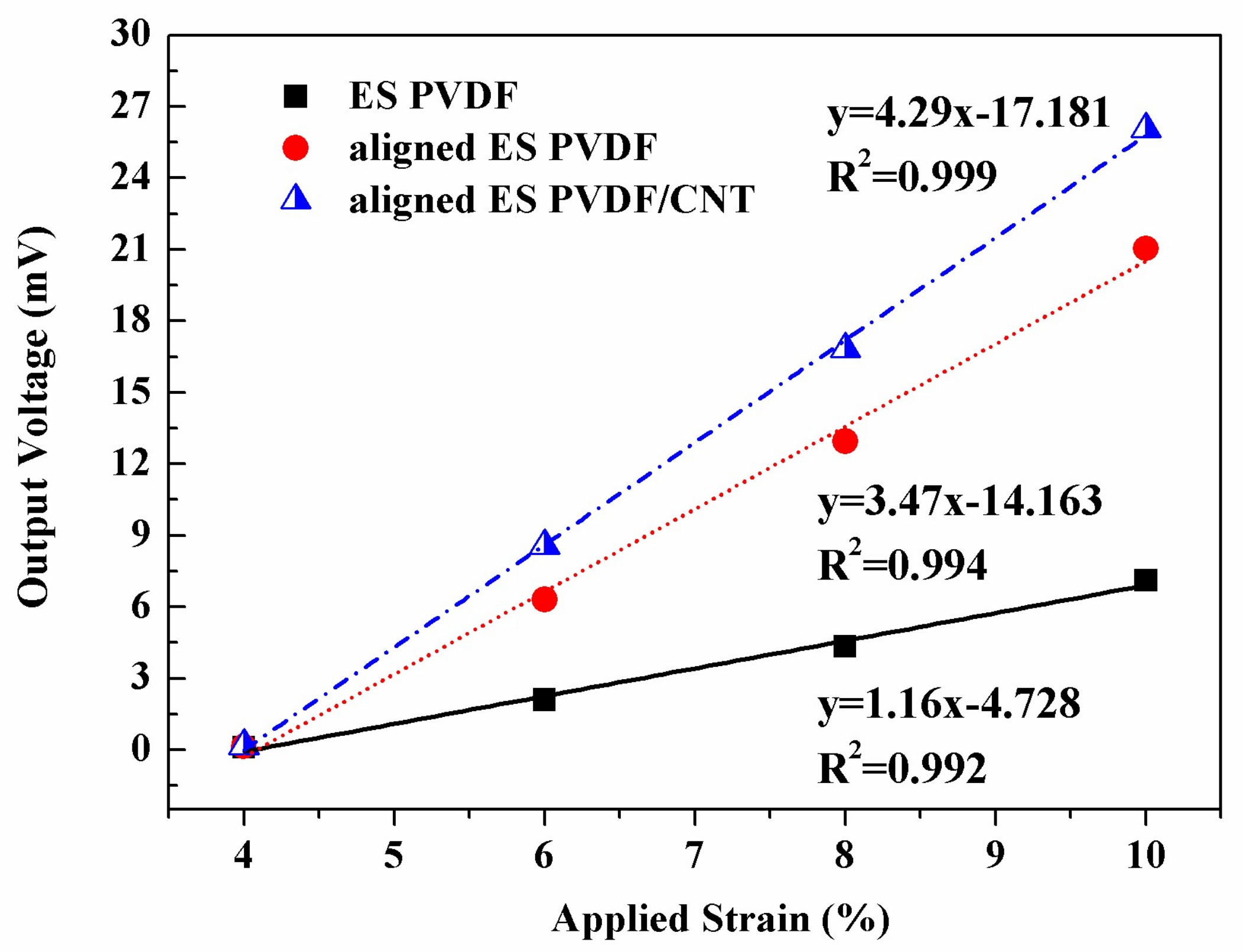
To compare the output voltages of the piezoelectric PVDF units, the applied strains of the PVDF samples were conversed to forces. The relationships between tensile strains and output voltages are plotted in Figure 7. The sensitivities under tension of the piezoelectric PVDF units containing randomly oriented electrospun PVDF, aligned electrospun PVDF, and PVDF/CNT are 1.16 mV/%, 3.47 mV/%, and 4.29 mV/%, respectively. The PVDF samples show higher sensitivities under tension than under compression, because the tension is applied in the direction vertical to the polarization direction of the PVDF samples [25].
2.5.3. Piezoelectric Responses under Dynamic Bending
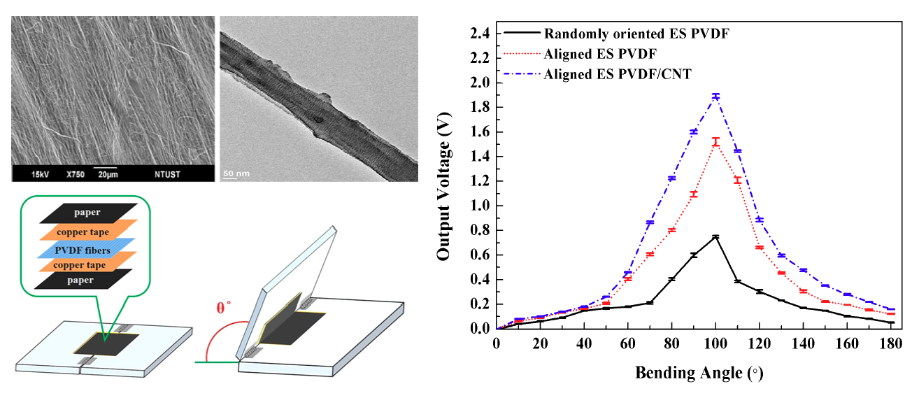
In addition to compression and tension, other kinds of forces appear in human motion. In this study, the PVDF samples were evaluated under bending forces to demonstrate their practical piezoelectric outputs. In the bending-induced piezoelectric response tests, the PVDF samples were cut into 3 × 3 cm2 squares. To maintain the flexibility of the PVDF samples, copper tapes were used as the electrodes and black Bristol paper was used as the insulating layers. The piezoelectric PVDF units were fixed by double-sided tape between two acrylic boards and bent to angles from 10° to 180°. Each piezoelectric output value induced by a certain bending angle was measured and averaged. The results are shown in Figure 8. The output voltages of all three PVDF samples reach the highest values when they are bent to 100°. The output voltage values of the randomly oriented electrospun PVDF, aligned electrospun PVDF, and PVDF/CNT are 0.75 V, 1.52 V, and 1.89 V, respectively. It can be seen that the output voltage values are decreased for bending angles of ≥110°. This observation is explained based on the following causes: the induced dipoles of the electrospun PVDF membranes are oriented parallel to the thickness direction. For increased bending angles, the PVDF membranes are folded. This decreases the piezoelectric output because of the dramatic decrease of the net dipole moment attributed to the opposite dipole arrangement in the folded structure [26].
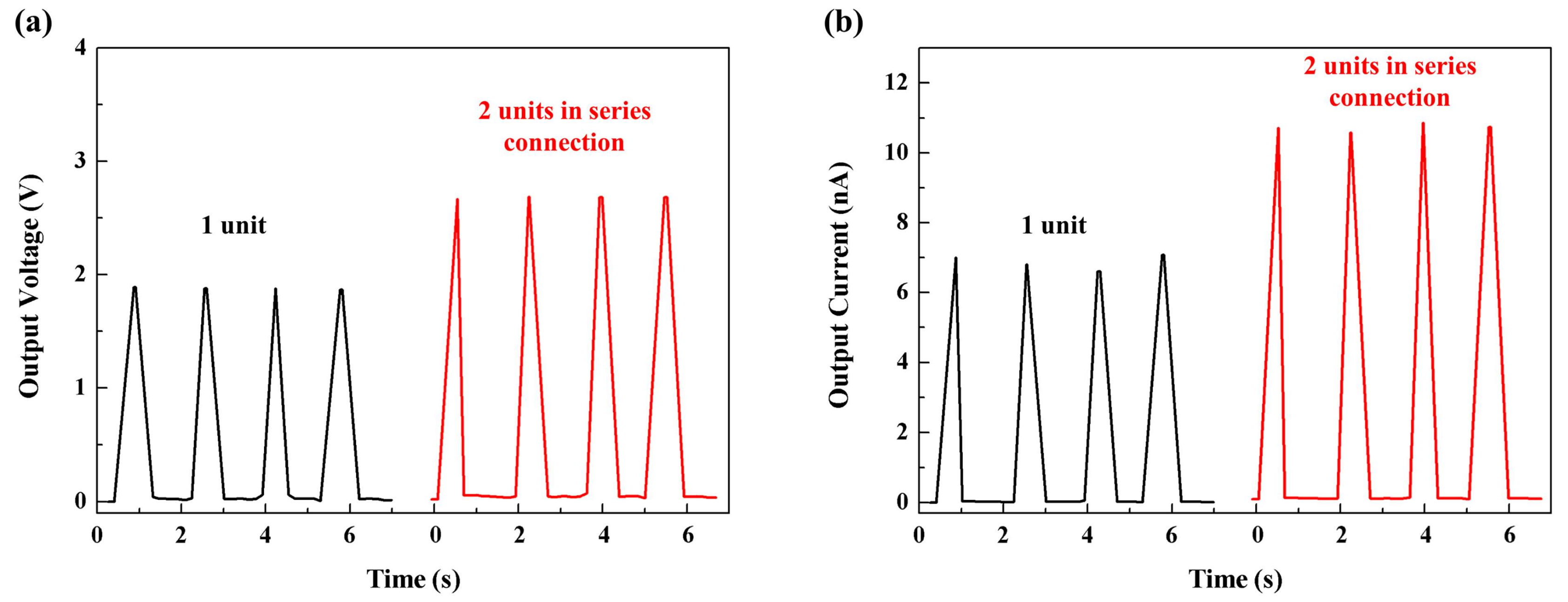
To enhance the output voltage and current, several piezoelectric units of aligned electrospun PVDF/CNT were connected in series and parallel and loaded by bending at 100°. The piezoelectric output results are shown in Figure 9. The output voltages and currents of the two piezoelectric PVDF units in series and parallel connections are 2.92 V and 11 nA, respectively. Although the output voltage and current are increased with the number of piezoelectric PVDF units in connection, the output values do not increase linearly. This is caused by internal current losses from resistance in the connecting wires, which induces insignificant increases in the voltage and current. The multiply connected piezoelectric PVDF units do show improved output voltage and current and increased overall sensitivity.
3. Materials and Methods
3.1. Materials
PVDF pellets (Kynar®720, Arkema Group, Colombes, France) with a molecular weight of 263,000 and multiwall CNT of 95% purity and diameters of 10–20 nm (Golden Innovation Business Company, Taipei, Taiwan) were used in this study.
3.2. Preparation of Aligned Electrospun PVDF/CNT Nanofibrous Membranes
A suspended CNT/n-dimethylformamide (DMF) solution was prepared by adding 0.025 g of CNT powder to 6 g of DMF solution and sonicating for 20 min at 40 Hz with an ultrasonic cell disruptor. Then, 2.2 g of PVDF pellets were added to the as-prepared CNT/DMF solution at 100 °C with stirring, and the solution was held at 25 °C. The PVDF/CNT solution (18 wt %) for ES was prepared by adding 4 mL acetone to the as-prepared PVDF/CNT solution to enhance evaporation.
An ES device consisting of an injection spinneret was powered by a syringe pump (KDS 101 Series, KD Scientific Inc., Holliston, MA, USA), which was connected to a Teflon tube attached to a stainless-steel needle (diameter = 0.23 mm). The electrostatic controller (SM 4030-24NIR, You-Shang Technical Corp., Taoyuan, Taiwan), connected to the spinneret and collector, was grounded. The PVDF nanofibrous membranes were directly electrospun and deposited on two kinds of collectors of a fixed copper grid and a rotating drum to obtain different morphologies in the electrospun membranes. The CNT content of electrospun PVDF/CNT nanofibrous membranes was 1 wt %.
3.3. Characterization
The morphologies of the electrospun nanofibrous membranes were analyzed using SEM (JSM-6390,JEOL Ltd., Akishima, Japan) at 20 kV. The membranes prepared by ES were directly placed onto a copper grid coated with a holey carbon film and examined through TEM (F20, Philips, Andover, MA, USA) operated at 200 kV.
During differential scanning calorimetry (DSC) (DSC-4000, Perkin Elmer, Waltham, MA, USA), the electrospun nanofibrous membranes were scanned from 25 to 230 °C at a rate of 20 °C/min and then maintained at isothermal conditions for 3 min at 230 °C. The membranes were subsequently cooled to ambient temperature at 20 °C/min. FTIR (FTIR-4600, JASCO, Easton, MD, USA) scans were recorded over the range 1500–650 cm−1 at the resolution of 4 cm−1.
A universal testing machine (QC-508M2, Cometech, Taichung, Taiwan) was used to perform tensile testing of the electrospun nanofibrous membranes at room temperature, according to ASTM D882. Dumbbell specimens with a gauge length of 33 mm and a width of 6 mm were prepared for each tensile test. The crosshead speed was 50 mm/min. All reported tensile properties were the average of at least five tests.
The piezoelectric coefficients of the poled electrospun nanofibrous membranes were analyzed with a wide-range d33 meter (d33, YE2730, APC International Ltd., Mackeyville, PA, USA). This system is used to directly measure the d33 values of piezoelectric materials. For the piezoelectric response characterization, the electrospun nanofibrous membranes were sandwiched between conductive electrodes and loaded with different types of mechanical forces. The piezoelectric responses of the electrospun nanofibrous membranes were measured using a source meter unit (SMU, Keithley 2400, Tektronix Inc., Beaverton, OR, USA), and the data were collected and observed by a computer.
4. Conclusions
In this study, PVDF membranes were prepared through ES, and the effects of morphology and β phase content on their piezoelectric properties were investigated. The conclusions are as follows:
- The randomly oriented electrospun PVDF, aligned electrospun PVDF, and aligned PVDF/CNT nanofibrous membranes were successfully prepared by using fixed or rotating collectors.
- By adjusting the ES parameters, the β content and the d33 value of the aligned electrospun PVDF are increased relative to those of randomly oriented electrospun PVDF, because the rotating drum provided additional mechanical poling to the aligned electrospun PVDF. The aligned PVDF/CNT showed even greater enhancements in β phase content and d33 value.
- The tensile sensitivities of the PVDF samples were much higher than the compressive sensitivities because the tension was applied vertical to the polarization direction of the PVDF membranes.
- When the PVDF samples were subjected to bending, the output voltage did not increase linearly with increased bending angles because of the complicated forces involved. However, the ease of achieving high electric outputs indicates that bending forces are promising sources with high sensing sensitivity and resolution.
Author Contributions
C.-M.W. supervised the experiments, and reviewed and revised the manuscript. M.-H.C. provided assistance in the experimental work, analyzed the results, and wrote the manuscript. W.-Y.Z. performed the experiments and analyzed the results. All authors have read and approved the final manuscript.
Funding
This research was funded by The Ministry of Science and Technology of Taiwan, ROC, under grant number: MOST 106-2218-E-035-012- and MOST 106-2221-E-011-138-.
Conflicts of Interest
The authors declare no conflict of interest.
References
- Nandi, A.K.; Mandelkern, L. The influence of chain structure on the equilibrium melting temperature of poly(vinylidene fluoride). J. Polym. Sci. Part B: Polym. Phys. 1991, 29, 1287–1297. [Google Scholar] [CrossRef]
- Cross, L.E. Ferroelectric materials for electromechanical transducer applications. Mater. Chem. Phys. 1996, 43, 108–115. [Google Scholar] [CrossRef]
- Humphreys, J.; Lewis, E.L.V.; Ward, I.M.; Nix, E.L.; McGrath, J.C. A study of the mechanical anisotropy of high-draw, low-draw, and voided PVDF. J. Polym. Sci. Part B: Polym. Phys 1998, 26, 141–158. [Google Scholar] [CrossRef]
- Ke, K.; Pötschke, P.; Jehnichen, D.; Fischer, D.; Voit, B. Achieving β-phase poly(vinylidene fluoride) from melt cooling: Effect of surface functionalized carbon nanotubes. Polymer 2014, 55, 611–619. [Google Scholar] [CrossRef]
- Ouyang, Z.W.; Chen, E.C.; Wu, T.M. Enhanced piezoelectric and mechanical properties of electroactive polyvinylidene fluoride/iron oxide composites. Mater. Chem. Phys. 2015, 149–150, 172–178. [Google Scholar] [CrossRef]
- Fakhri, P.; Mahmood, H.; Jaleh, B.; Pegoretti, A. Improved electroactive phase content and dielectric properties of flexible PVDF nanocomposite films filled with Au- and Cu-doped graphene oxide hybrid nanofiller. Synthetic Met. 2016, 220, 653–660. [Google Scholar] [CrossRef] [Green Version]
- Merlini, C.; Barra, G.; Medeiros Araujo, T.; Pegoretti, A. Electrically pressure sensitive poly(vinylidene fluoride)/polypyrrole electrospun mats. RSC Adv. 2014, 4, 15749–15758. [Google Scholar] [CrossRef]
- Merlini, C.; Barra, G.M.D.O.; Araujo, T.M.; Pegoretti, A. The effect of compressive stress on the electrically resistivity of poly(vinylidene fluoride)/polypyrrole blends. Synthetic Met. 2014, 196, 186–192. [Google Scholar] [CrossRef]
- Merlini, C.; Pegoretti, A.; Araujo, T.M.; Ramoa, S.D.A.S.; Schreiner, W.H.; Barra, G.M.D.O. Electrospinning of doped and undoped-polyaniline/poly(vinylidene fluoride) blends. Synthetic Met. 2016, 213, 34–41. [Google Scholar] [CrossRef] [Green Version]
- Levi, N.; Czerw, R.; Xing, S.; Iyer, P.; Carroll, D.L. Properties of Polyvinylidene Difluoride-Carbon Nanotube Blends. Nano Lett. 2004, 4, 1267–1271. [Google Scholar] [CrossRef]
- Ahn, Y.; Lim, J.Y.; Hong, S.M.; Lee, J.; Ha, J.; Choi, H.J.; Seo, Y. Enhanced Piezoelectric Properties of Electrospun Poly(vinylidene fluoride)/Multiwalled Carbon Nanotube Composites Due to High β-Phase Formation in Poly(vinylidene fluoride). J. Phys. Chem. C. 2013, 117, 11791–11799. [Google Scholar] [CrossRef]
- Huang, S.; Yee, W.A.; Tjiu, W.C.; Liu, Y.L.; Kotaki, M.; Boey, Y.C.F.; Ma, J.; Liu, T.; Lu, X. Electrospinning of Polyvinylidene Difluoride with Carbon Nanotubes: Synergistic Effects of Extensional Force and Interfacial Interaction on Crystalline Structures. Langmuir 2008, 24, 13621–13626. [Google Scholar] [CrossRef] [PubMed]
- Mago, G.; Kalyon, D.M.; Fisher, F.T. Membranes of Polyvinylidene Fluoride and PVDF Nanocomposites with Carbon Nanotubes via Immersion Precipitation. J. Nanomater. 2008, 759825. [Google Scholar] [CrossRef]
- Huang, X.; Jiang, P.; Kim, C.; Liu, F.; Yin, Y. Influence of aspect ratio of carbon nanotubes on crystalline phases and dielectric properties of poly(vinylidene fluoride). Eur. Polym. J. 2009, 45, 377–386. [Google Scholar] [CrossRef]
- Layek, R.K.; Samanta, S.; Chatterjee, D.P.; Nandi, A.K. Physical and mechanical properties of poly(methyl methacrylate)-functionalized graphene/poly(vinylidine fluoride) nanocomposites: Piezoelectric β polymorph formation. Polymer 2010, 51, 5846–5856. [Google Scholar] [CrossRef]
- Wang, J.; Wu, J.; Xu, W.; Zhang, Q.; Fu, Q. Preparation of poly(vinylidene fluoride) films with excellent electric property, improved dielectric property and dominant polar crystalline forms by adding a quaternary phosphorus salt functionalized graphene. Compos. Sci. Technol. 2014, 91, 1–7. [Google Scholar] [CrossRef]
- Kim, J.; Loh, K.J.; Lynch, J.P. Piezoelectric polymeric thin films tuned by carbon nanotube fillers. In Proceedings of SPIE: Sensors and Smart Structures Technologies for Civil, Mechanical, and Aerospace Systems 2008; International Society for Optics and Photonics: Bellingham, WA, USA, 2008; Volume 6932, p. 693232. [Google Scholar]
- Wu, C.M.; Chou, M.H. Polymorphism, piezoelectricity and sound absorption of electrospun PVDF membranes with and without carbon nanotubes. Compos. Sci. Technol. 2016, 127, 127–133. [Google Scholar] [CrossRef]
- Baji, A.; Mai, Y.W.; Wong, S.C.; Abtahi, M.; Chen, P. Electrospinning of polymer nanofibers: Effects on oriented morphology, structures and tensile properties. Compos. Sci. Technol. 2010, 70, 703–718. [Google Scholar] [CrossRef]
- Wang, L.Y.; Ma, S.Y.; Wu, D.Z. Electrospinning of aligned PVDF nanofibers with piezoelectricity and its application in pressure sensors. Opt. Precis. Eng. 2016, 24, 2498–2504. [Google Scholar] [CrossRef]
- Wang, Y.R.; Zheng, J.M.; Ren, G.Y.; Zhang, P.H.; Xu, C. A flexible piezoelectric force sensor based on PVDF fabrics. Smart Mater. Struc. 2011, 20, 045009. [Google Scholar] [CrossRef]
- Liu, Z.H.; Pan, C.T.; Lin, L.W.; Huang, J.C.; Ou, Z.Y. Direct-write PVDF nonwoven fiber fabric energy harvesters via the hollow cylindrical near-field electrospinning process. Smart Mater. Struc. 2014, 23, 025003. [Google Scholar] [CrossRef]
- Yu, L.; Wang, S.; Li, Y.; Chen, D.; Liang, C.; Lei, T.; Sun, D.; Zhao, Y.; Wang, L. Piezoelectric performance of aligned PVDF nanofibers fabricated by electrospinning and mechanical spinning. In Proceedings of the 13th IEEE International Conference on Nanotechnology, Beijing, China, 5–8 August 2013; pp. 962–966. [Google Scholar]
- Issa, A.A.; Al-Maadeed, M.A.; Luyt, A.S.; Ponnamma, D.; Hassan, M.K. Physico-mechanical, dielectric, and piezoelectricpProperties of PVDF electrospun mats containing silver nanoparticles. J. Carbon Res. 2017, 3, 30. [Google Scholar] [CrossRef]
- Bowen, C.R.; Kim, H.A.; Weaver, P.M.; Dunn, S. Piezoelectric and ferroelectric materials and structures for energy harvesting applications. Energy Environ. Sci. 2014, 7, 25–44. [Google Scholar] [CrossRef] [Green Version]
- Mandal, D.; Yoon, S.; Kim, K.J. Origin of Piezoelectricity in an Electrospun Poly(vinylidene fluoride-trifluoroethylene) Nanofiber Web-Based Nanogenerator and Nano-Pressure Sensor. Macromol. Rapid Commun. 2011, 32, 831–837. [Google Scholar] [CrossRef] [PubMed]
Figure 1.
SEM images of: (a) randomly oriented electrospun PVDF; (b) aligned electrospun PVDF; and (c) aligned electrospun PVDF/CNT. (d) TEM image of aligned electrospun PVDF/CNT nanofiber.
Figure 1.
SEM images of: (a) randomly oriented electrospun PVDF; (b) aligned electrospun PVDF; and (c) aligned electrospun PVDF/CNT. (d) TEM image of aligned electrospun PVDF/CNT nanofiber.
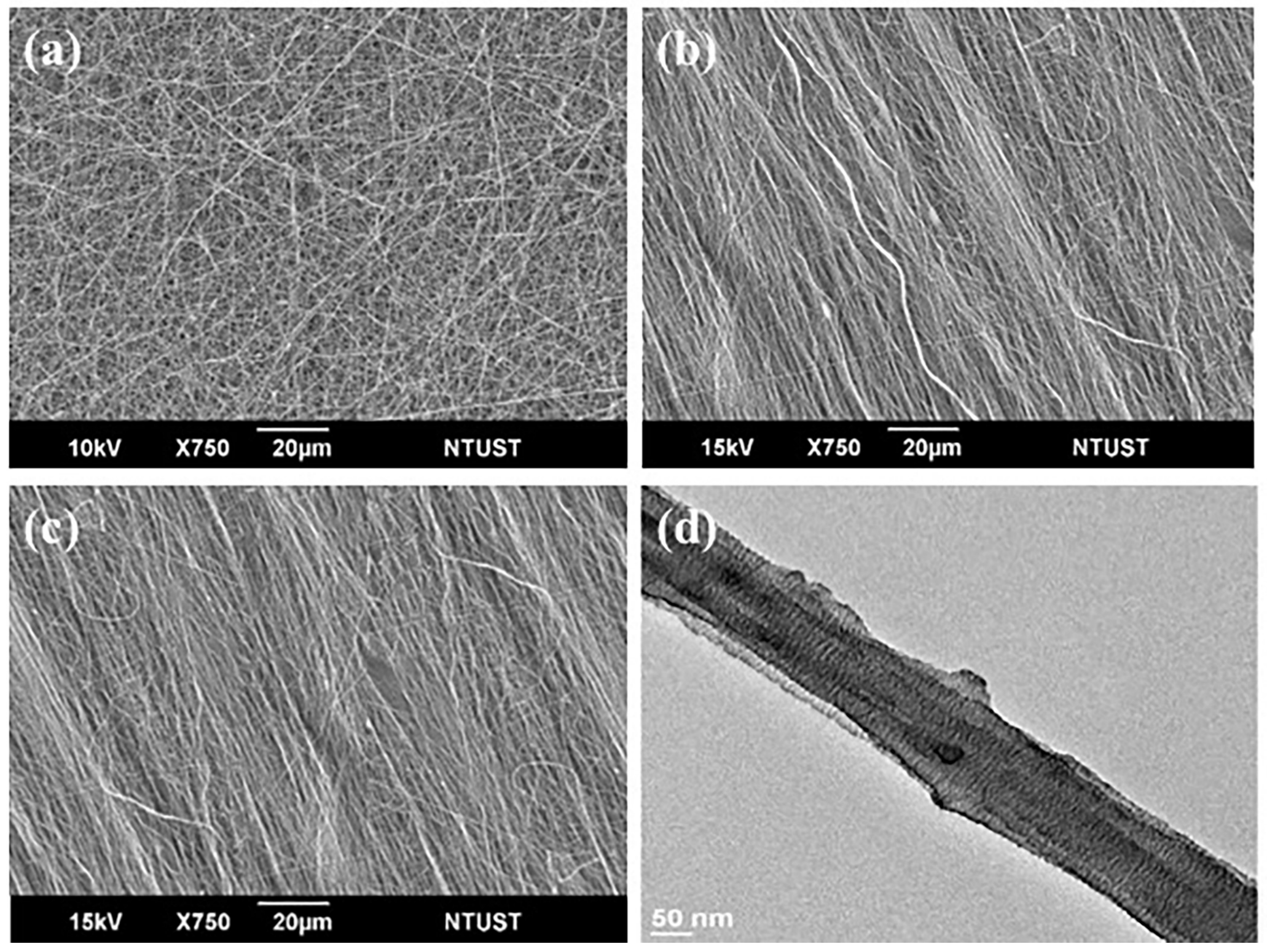
Figure 2.
FTIR spectra for the PVDF samples.

Figure 3.
Tensile load-displacement curves of PVDF samples.

Figure 4.
Piezoelectric output voltage waves of the piezoelectric units with: (a) randomly oriented electrospun PVDF; (b) aligned electrospun PVDF; and (c) aligned electrospun PVDF/CNT under compressive forces from 200 N to 350 N.
Figure 4.
Piezoelectric output voltage waves of the piezoelectric units with: (a) randomly oriented electrospun PVDF; (b) aligned electrospun PVDF; and (c) aligned electrospun PVDF/CNT under compressive forces from 200 N to 350 N.

Figure 5.
Applied compressive force vs. output voltage of the piezoelectric PVDF units.

Figure 6.
Piezoelectric output voltage waves of the piezoelectric units with: (a) randomly oriented electrospun PVDF; (b) aligned electrospun PVDF; and (c) aligned electrospun PVDF/CNT under tensile strains from 4% to 10%.
Figure 6.
Piezoelectric output voltage waves of the piezoelectric units with: (a) randomly oriented electrospun PVDF; (b) aligned electrospun PVDF; and (c) aligned electrospun PVDF/CNT under tensile strains from 4% to 10%.

Figure 7.
Applied tensile strain vs. output voltage of the piezoelectric PVDF units.

Figure 8.
Bending angle vs. output voltage of the piezoelectric PVDF units.

Figure 9.
(a) Output voltage waves of the piezoelectric units with aligned electrospun PVDF/CNT under 100° bending in series connection. (b) Output current waves of the piezoelectric units with aligned electrospun PVDF/CNT under 100° bending in parallel connection.
Figure 9.
(a) Output voltage waves of the piezoelectric units with aligned electrospun PVDF/CNT under 100° bending in series connection. (b) Output current waves of the piezoelectric units with aligned electrospun PVDF/CNT under 100° bending in parallel connection.


Table 1.
F(β) values and piezoelectric coefficients of the PVDF samples.
| Sample | F(β) (%) | d33 (pC/N) |
|---|---|---|
| Randomly oriented electrospun PVDF | 79 ± 3 | 16.8 ± 1.4 |
| Aligned electrospun PVDF | 88 ± 1 | 27.4 ± 1.5 |
| Aligned electrospun PVDF/CNT | 89 ± 2 | 31.3 ± 2.1 |
© 2018 by the authors. Licensee MDPI, Basel, Switzerland. This article is an open access article distributed under the terms and conditions of the Creative Commons Attribution (CC BY) license (http://creativecommons.org/licenses/by/4.0/).
Share and Cite
MDPI and ACS Style
Wu, C.-M.; Chou, M.-H.; Zeng, W.-Y. Piezoelectric Response of Aligned Electrospun Polyvinylidene Fluoride/Carbon Nanotube Nanofibrous Membranes. Nanomaterials 2018, 8, 420. https://doi.org/10.3390/nano8060420
AMA Style
Wu C-M, Chou M-H, Zeng W-Y. Piezoelectric Response of Aligned Electrospun Polyvinylidene Fluoride/Carbon Nanotube Nanofibrous Membranes. Nanomaterials. 2018; 8(6):420. https://doi.org/10.3390/nano8060420
Chicago/Turabian StyleWu, Chang-Mou, Min-Hui Chou, and Wun-Yuan Zeng. 2018. "Piezoelectric Response of Aligned Electrospun Polyvinylidene Fluoride/Carbon Nanotube Nanofibrous Membranes" Nanomaterials 8, no. 6: 420. https://doi.org/10.3390/nano8060420
Note that from the first issue of 2016, this journal uses article numbers instead of page numbers. See further details here.