Article

Nano-Impact (Fatigue) Characterization of As-Deposited Amorphous Nitinol Thin Film

1
College of Engineering, Alfaisal University, P.O. Box 50927, Riyadh, 11533, Saudi Arabia
2
School of Engineering and Physical Sciences, Heriot-Watt University, Edinburgh, EH14 4AS, UK
3
Thin Film Centre, Scottish Universities Physics Alliances (SUPA), University of the West of Scotland, Paisley, PA1 2BE, UK
*
Author to whom correspondence should be addressed.
Coatings 2012, 2(3), 195-209; https://doi.org/10.3390/coatings2030195
Submission received: 14 June 2012 / Revised: 8 August 2012 / Accepted: 13 August 2012 / Published: 31 August 2012
(This article belongs to the Special Issue Advances in Multifunctional Coatings for Next Generation Applications)

Abstract

:
This paper presents nano-impact (low cycle fatigue) behavior of as-deposited amorphous nitinol (TiNi) thin film deposited on Si wafer. The nitinol film was 3.5 µm thick and was deposited by the sputtering process. Nano-impact tests were conducted to comprehend the localized fatigue performance and failure modes of thin film using a calibrated nano-indenter NanoTest™, equipped with standard diamond Berkovich and conical indenter in the load range of 0.5 mN to 100 mN. Each nano-impact test was conducted for a total of 1000 fatigue cycles. Depth sensing approach was adapted to understand the mechanisms of film failure. Based on the depth-time data and surface observations of films using atomic force microscope, it is concluded that the shape of the indenter test probe is critical in inducing the localized indentation stress and film failure. The measurement technique proposed in this paper can be used to optimize the design of nitinol thin films.

Nomenclature

E: Elastic modulus; Ei: Elastic modulus of indenter; Er: Reduced elastic modulus; Es: Elastic modulus of the specimen; H: Hardness; h: Depth (displacement); hf: Final depth (displacement); hfd1: Forward depth at first impact cycle; hfdm: Maximum forward depth deviation (start of backward deviation); P: Force, Impact load; Nbd: Number of impact (fatigue) cycles after which negative depth starts (backward depth deviation); Nfdm: Number of impact (fatigue) cycles after which backward depth deviation starts; Ra: Average surface roughness; σ, σc: Residual stress, Compressive residual stress; νs, νi: Poisson’s ratio (substrate or indenter); ts: Thickness of the Si-substrate; tf: Thickness of nitinol film; f: Film; i: Indenter; s: Substrate; AFM: Atomic Force Microscope; BD: Backward Depth Deviation; DC: Direct Current; FD: Forward Depth Deviation; MEMS: Micro-Electro-Mechanical Systems; RF: Radio Frequency; sccm: Standard Cubic Centimeter per Minute; SEM: Scanning Electron Microscope; SMAs: Shape Memory Alloys.

1. Introduction

Nitinol based shape memory alloys (SMAs) possess a unique combination of engineering properties such as shape memory and superplasticity and can be used in various applications [1,2]. Thin film SMAs have been recognized as a promising material in the field of micro-electro-mechanical system (MEMS) applications [1,2]. Nitinol (TiNi) based thin film SMAs are considered as a core technology for actuation of some MEMS devices, where large force and stroke are essential in condition of low duty cycles or intermittent operations, and in extreme environment, such as radioactive, space, biological and corrosive conditions [1,2]. During applications, these nitinol thin films may suffer from several forms of fatigue damage that range from component shape change to catastrophic failures [2,3]. These films should have low residual stress to prevent deformation, precise deformation control, good adhesion to substrate, durable and reliable shape memory effects, and good resistance to wear [1].
There are few studies on the fatigue performance of nitinol based shape memory alloy thin films. For free-standing TiNi thin films, studies [1,4] considered tensile tests to characterize the fatigue properties, where it has been indicated that they need tens of cycles at macro-scale before the stability of shape memory effects. Other studies [5,6] have investigated the fatigue of the constrained TiNi films using the changes of recovery stress during cycling, and found that the recovery stress of the TiNi films from curvature measurement decreased in the initial cycles, and became stable after thousands of cycles. This reduction of the recovery stress is believed to have resulted from the dislocation movement, grain boundary sliding, void formation, or partial de-bonding at the film-substrate interfaces, non-recoverable plastic deformation, and changes in stress, etc. [5].
Understanding the nano-impact (fatigue) behavior of nitinol thin films (amorphous and crystallized) is therefore critical for optimizing film design for improved durability and performance [1]. There are no previous studies on the behavior of nitinol based thin film-substrate systems during nano-impact (localized fatigue) testing. In recent years, there has been a considerable improvement in instrumented indentation testing systems and it is now possible to monitor localized impact fatigue behavior of materials or thin films at nano-scales [7,8,9,10]. If the impact fatigue process is recorded for larger number cycles and long periods [7], the value of such test (deformation or fracture in thin film-substrate materials) can be considerably enhanced. Impact based fatigue (low-cycle) testing involves cyclic-loading of the test sample via a rigid indenter, and serves as an alternate approach for measuring the fatigue properties of materials [8,9,10,11]. Impact fatigue failure can be caused by various mechanisms, such as dislocation movement, crack initiation and crack closure. Since the impact fatigue damage starts with the crack initiation and propagation [7,8,9,10,11], the interpretation of impact fatigue test will depend on the characteristics of the loading history. In the absence of other reliable techniques to measure localized fatigue at nano/micro scales, and considering the benefits that may be realized using the instrumented indentation technique to measure impact fatigue, further research in this area is inevitable, particularly in areas related to tribological studies of TiNi SMA thin films for different types of MEMS applications (e.g., micro-grippers, micro-pumps, micro-mirror, etc.) [1].
A number of investigations (e.g., [12,13,14,15]) have performed nanoscale contact fatigue using various shapes of indenters for materials other than shape memory alloys. These investigations take advantage of the features in the real time force-displacement (P-h), displacement-time (h-t) or stiffness curves recorded during repeated loading/unloading of bulk materials and thin films. In the current investigation, a real-time depth (displacement) sensing approach was adapted to investigate the mechanisms of nano-impact (low-cycle fatigue) failure in nitinol (as-deposited amorphous) thin film. The mechanical behavior of amorphous and crystallized nitinol thin films is expected to be different [1]. Therefore, as a first step in the current investigation the film has been investigated for as-deposited amorphous TiNi and further nano-impact comparison studies are inevitable with crystallized nitinol thin films used as a shape memory material.

2. Experimental Section

2.1. Test Specimen

TiNi films of 3.5 µm thickness were deposited on Si (100) wafer of 450 µm thickness by co-sputtering a TiNi target at RF power density of 6.88 W·cm−2 and a Ti target at DC power density of 1.20 W·cm−2. During deposition, the substrate holder was rotated to enhance film uniformity without external heating. The base pressure of the main chamber was 1.33×10⁻⁵ Pa. The target-to-substrate distance was 100 mm, and Ar gas pressure was 0.133 Pa with a flow rate of 20 sccm. The compositions were determined by the energy dispersive X-ray microanalysis (EDX), and the film had an average Ti:Ni ratio of 50.2:49.8. X-ray diffraction analysis has been done for the as-deposited TiNi film. The curvature changes of the Si wafers before and after coating were measured using a Tencor FLX-2908 laser system. Film surface morphology was characterized using an atomic force microscopy (AFM). Further details of these thin films preparation and characterization have been reported elsewhere [16,17,18,19].

2.2. Nanoindentation Testing and Measurements

Nanoindentation measurements (e.g., hardness and elastic modulus) of as-deposited TiNi film at 1 mN load were performed using a calibrated NanoTest™ system (Micro Materials Ltd., Wrexham, UK) with a standard diamond Berkovich indenter. Further detail of the testing instrument and measurement can be seen elsewhere [8,9]. The P-h profiles were analyzed using standard methods with the area function for the Berkovich indenter which was determined by indentations into fused silica with elastic modulus of 69.9 GPa. The raw data (P-h profile) were used to evaluate hardness (H) and reduced elastic modulus (Er) of film without influencing the substrate [14]. The elastic modulus (Ei) and Poisson ratio (νi) of the diamond indenter was taken as 1140 GPa and 0.07 [14], whereas, to calculate the elastic modulus (Es) of the specimen (nitinol thin films), the Poisson ratio for TiNi thin film (νs) was taken as 0.33 [20].

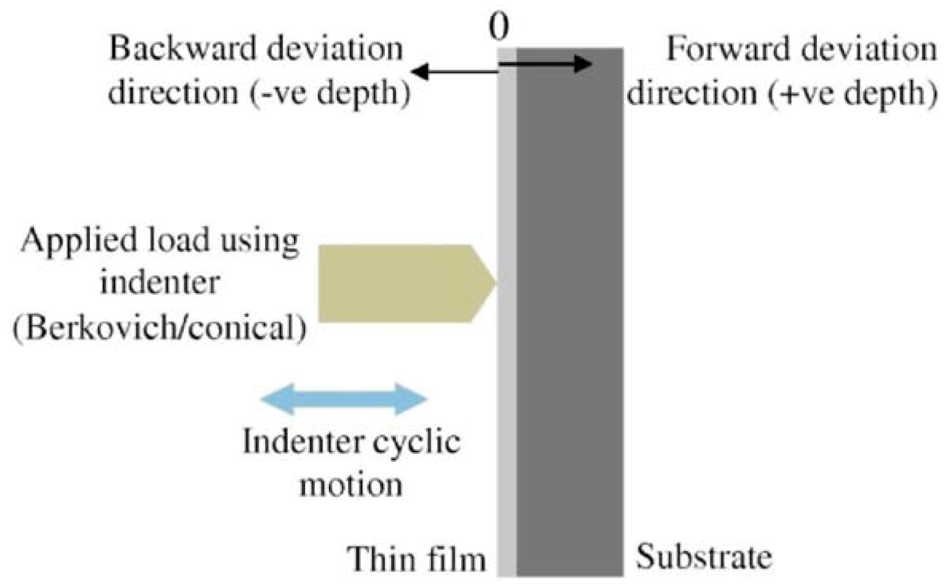
2.3. Nano-Impact Testing and Measurements

Nano-impact (low-cycle fatigue) experiments of as-deposited TiNi film were conducted using the calibrated NanoTest™ system (Micro Materials Ltd., Wrexham, UK) equipped with a standard diamond Berkovich and conical nanoindenter tip [7,14]. Figure 1 shows the schematic of operation of nano-impact test and depth deviation with reference to the specimen surface. A solenoid connected to a timed relay was used to produce the repetitive indenter impact on the sample surface. The indenter was accelerated from a distance of 10 µm from the surface to produce each impact with impact force ranged from 0.5 mN to 100 mN. Standard diamond Berkovich and conical nanoindenters were used to compare the effect of contact fatigue failure mechanism. The loading and unloading cycles for nano-impact tests involved linearly loading the specimen to full load in one second and then releasing 100% of the test load in one second with zero hold time at the peak load. Each test was conducted for a total of 1000 fatigue cycles at the same location of the specimen surface [7]. A total of five repeats for each indenter shapes were conducted at each load (Table 1). The evolution of surface impact response was recorded in real-time by continuously monitoring the change in the indenter tip position (depth vs. time). This technique was adapted to understand the mechanisms of nano-impact (low-cycle fatigue) failure of constrained TiNi film which could be different from those of free-standing films due to substrate effect, stress gradient effect, residual stress, etc. [1].
Figure 1. Schematic of operation of nano-impact test (NanoTest™) and depth deviation with reference to the specimen surface.
Coatings 02 00195 g001
Table 1. Experimental matrix for nano-impact (low-cycle fatigue) testing.
Sl. No.Impact load, P (mN)No. of impactsTotal test time (s)Indenter shape (number of repeats)
BerkovichConical
10.51000200055
211000200055
3101000200055
41001000200055
Post-impact testing, the residual impression was characterized using an in-situ AFM (Nanosurf® Nanite, SPM S50, Liestal, Switzerland). The AFM images were recorded by scanning the specimen surface with a scan rate of 1 Hz. Image processing and data analysis software (Nanite B, version 2.2.0; Nanosurf AG: Liestal, Switzerland, 2009) was used for image analysis. Nano-impact tests and AFM measurements were taken at the instrument chamber temperature which was set (at 23 °C). The microstructure of the film surface and impact residual impression was examined by a scanning electron microscope (SEM).

3. Results

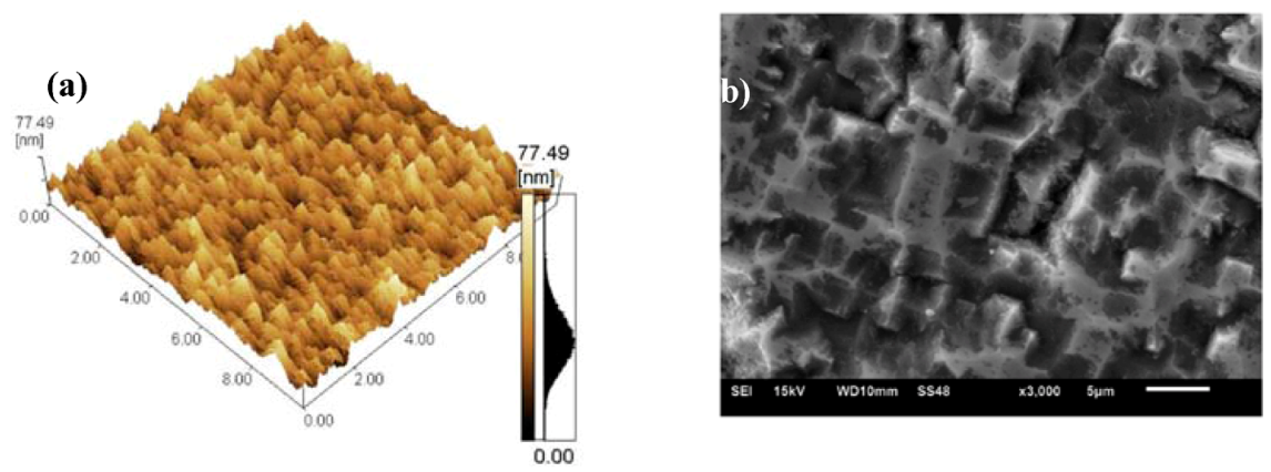
3.1. Film Characterization

XRD analysis revealed that the deposited Ti50.2Ni49.8 film was amorphous without apparent crystalline structure. The measured value of pre-existing residual stress from the curvature method at room temperature (293 K) is about 50 MPa to 100 MPa (compressive). Figure 2a shows the AFM image of a large area (10 μm × 10 μm) of the TiNi film surface, revealing the smooth nature of the as-deposited film, whereas, Figure 2b shows the SEM image of a much larger area. The film hardness and modulus from the nanoindentation results are 4.5 ± 0.8 GPa, and 69 ± 3 GPa, respectively.
Figure 2. (a) AFM image of as-deposited TiNi film; (b) SEM image of as-deposited TiNi film.
Coatings 02 00195 g002

3.2. Nano-Impact Testing of TiNi Thin Film

Figure 3Figure 6 show typical depth vs. time curves of nano-impact obtained at loads of 0.5 mN, 1 mN, 10 mN and 100 mN under Berkovich and conical indenters, respectively. These figures also reveal the corresponding magnified view of the early stage of nano-impacts.
Figure 3. Nano-impact testing at 0.5 mN load: (i) Full record of impact depth-time measurement; (ii) corresponding magnified boxed-view of early stage of impacts.
Coatings 02 00195 g003
The nano-impact experiments using Berkovich and conical indenters indicated that the indenter penetration is minimal at the first impact and then the penetration increment is gradual for loads as low as 0.5 mN (Figure 3a,b). It should be noted that each hysteresis curve (depth vs. time) is forward progressing during early stage of impact and then the increment is largely linear for much of the cycle at a load of 0.5 mN.
Figure 4. Nano-impact testing at 1 mN load: (i) Full record of impact depth-time measurement; (ii) corresponding magnified boxed-view of early stage of impacts (hfd1: forward depth deviation at first impact cycle, hfdm: maximum forward depth deviation, Nfdm: number of impact cycle at the maximum forward depth deviation, Nbd: number impact cycles after which negative depth starts, and hf: depth deviation at the final impact cycle).
Coatings 02 00195 g004
Figure 5. Nano-impact testing at 10 mN load: (i) Full record of impact depth-time measurement; (ii) corresponding magnified boxed-view of early stage of impacts.
Coatings 02 00195 g005
Figure 6. Nano-impact testing at the highest load of 100 mN: (i) Full record of impact depth-time measurement; (ii) corresponding AFM image of residual nano-impacts.
Coatings 02 00195 g006
At the moderate loads such as 1 mN and 10 mN (Figure 4 and Figure 5), it should be noted that each hysteresis curve is forward progressing during early stage of impact, reaches it maximum penetration, and then the depth decreases (defined as backward depth deviation) linearly for much of the cycles. It should also be noted that the backward depth deviation at the final impact cycle (e.g., Figure 4 and Figure 5) indicate two types of deviation (Types I and II). Type I indicates that the final impact depth (at 1000 impacts) is below zero, hf < 0 (e.g., Figure 4a(i), Figure 4b(i) and Figure 5a(i)), whereas, Type II indicates that the final impact depth is above zero, hf > 0 (e.g., Figure 5b(ii)).
The nano-impact response can thus be determined from the real-time depth and the corresponding number of impact cycles. Figure 4b presents and summarizes the typical features of the hysteresis curve (depth vs. time) in forward or backward progressing modes [7]: (a) forward depth deviation at first impact cycle, hfd1, (b) maximum forward depth deviation, hfdm, (c) number of impact cycle at the maximum forward depth deviation, Nfdm, (d) number impact cycles after which negative depth starts, Nbd, and (e) depth deviation at the final impact cycle, hf. The statistical appearance of both forward and backward depth deviation for the TiNi film is listed in Table 2.
At the highest load of 100 mN (Figure 6), the hysteresis curve progressed during early stage of impact and progressed at relatively lower rate for later stage of impacts. It should also be noted that indenter penetration has occurred immediately with the first impact (higher for Berkovich indenter). This was followed by a continuous increase in the indenter penetration with numerous abrupt depth changes, which might be attributed to the adhesive failure of the film-substrate system. As observed from AFM images (e.g., Figure 6(ii) for 100 mN load), no surface cracking and delamination of the film occurred at this load.
Table 2. Summary of depth-time profile characteristics.
Impact load, P (mN)BerkovichConical
FD out of 5BD out of 5FD out of 5BD out of 5
0.55050
105; *(3−, 2+)05; *(3−, 2+)
1005; *(2−, 3+)05; *(1−, 4+)
10014; *(0−, 4+)50
FD is forward depth deviation, BD is backward depth deviation (data in the asterisk * marked brackets indicate the occurrence and the type of backward depth deviation where minus sign (−) indicate that the final impact depth is below zero, h < 0; plus sign (+) indicate that the final impact depth is above zero, h > 0).

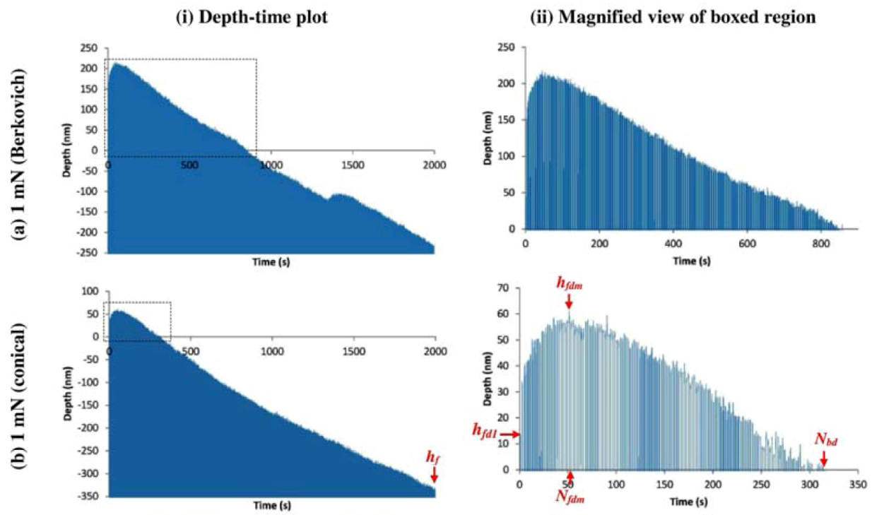
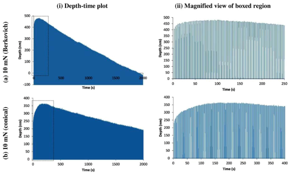
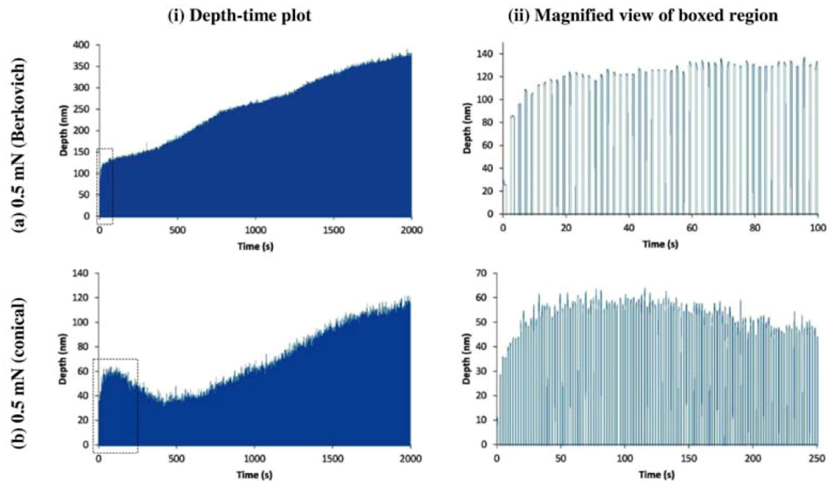
3.3. Features in Nano-Impact Depth vs. Time Curve

The nano-impact (low-cycle fatigue) response can be determined from the depth and corresponding number of impact cycles for both forward and backward depth deviation (depth vs. time) curves, as indicated in Figure 4b. Figure 7a indicates the features of the forward depth deviation at first impact cycle (hfd1) for both forward and backward depth deviation curves, whereas, Figure 7b,c indicate the features of the backward depth deviation related to the maximum forward depth deviation (hfdm), and the corresponding number of impact cycle (Nfdm).
Figure 7. Nano-impact test response: (a) Forward depth deviation at first impact cycle, hfd1. (b) Maximum forward depth deviation, hfdm. (c) Number of impact cycle at the maximum forward depth deviation, Nfdm. (d) Number impact cycles after which negative depth starts, Nbd.
Coatings 02 00195 g007
As shown in Figure 7a, due to sharp tip of Berkovich indenter, the forward depth deviation at first impact cycle (hfd1) is higher compared to conical indenter and increases with the impact load. As shown in Figure 7b and Figure 7c, maximum forward depth deviation (hfdm) increases and the corresponding number of impact cycles (Nfdm) also increases with the impact loads, indicating the influence of impact loads. As mentioned earlier in Figure 4b(ii), the number of impact cycles after which negative depth deviation starts (Nbd) increases with the impact loads, shown here for those loads where it appears (Figure 7d). The average values of Nbd indicate that the conical indenter delays the initiation of negative depth deviation compared to Berkovich indenter.
Figure 8. Depth at the final impact, hf: (a) Berkovich indenter. (b) Conical indenter [the depth at the final 1000th impact (hf) indicates that it can be below zero, hf < 0 (backward depth deviation of Type I) or above zero, hf > 0 (forward depth deviation, or backward depth deviation of Type II)].
Coatings 02 00195 g008
Figure 9. Schematic of nitinol thin film behavior during nano-impact (fatigue) under Berkovich (or conical) indenter showing the types of depth deviation: (a) Forward depth deviation. (b) Backward depth deviation of type I. (c) Backward depth deviation of type II (f: film, s: substrate, i: indenter).
Coatings 02 00195 g009
Also, as shown earlier in Figure 4b(i), the variation in the depth at the final 1000th impact (hf) at all four load can be seen in Figure 8, where it indicates that the final impact depth can be below zero (backward depth deviation of Type I, Figure 9b), above zero (forward depth deviation, Figure 9a; or backward depth deviation of Type II, Figure 9c) or equal to zero (no depth deviation).

4. Discussion

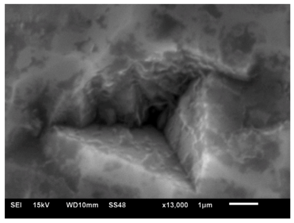
4.1. Impact Residual Impression

Impact (fatigue) testing is a valuable tool in elucidating the adhesion properties of thin films in a film-substrate system [7,8,9,10,11,12,13,14,15]. The material can accommodate the indenter by elastic or plastic deformation, local cracking, or a combination of these accommodation mechanisms [10,21]. Most commonly, the material is assessed by the size of the impression and/or by the cracking/deformation pattern left on the surface once the indenter has been removed [21,22,23]. Based on indenter geometry (mainly included angle and tip curvature radius), one indenter shape can have advantage over another depending on the application [24], e.g., in thin film investigations designers are interested in evaluating the film behavior and properties without being influence by the substrate material [25].
The plastic zone around an impact (or indentation) zone can drive a lateral crack along a weak film-substrate interface, leading to film delamination [26]. Residual deposition stresses can aggravate the delamination by causing buckling in the film [7,14,15,26]. The delamination is usually evident as surface uplift around the impact, enabling measurement of the crack size and calculation of interface toughness [26]. As mentioned above, results (depth vs. time curve) indicate both forward and backward depth deviation. For both indenters, no cracking in the thin film was observed at the given AFM resolution. However, the subsurface interfacial delamination (buckling or surface uplift around the impact [7,14,15,26], Figure 9) failure can be associated with a distinct features in depth vs. time curve indicating backward depth deviation (at 1 mN, 10 mN and 100 mN loads, repetitions shown in Table 2). This behavior of backward depth deviation has been previously investigated [7] in nano-impact (1000 impacts at 1 mN load using NanoTest™ system) testing of 100 nm thick DLC film. It has been indicated that the film delamination at the interface is possible without surface cracking and significant reduction in contact depth (i.e., backward depth deviation). The depth deviation has been further investigated [15] during nano-fatigue test using TriboIndenter® system (Triboscope, Hysitron Inc., Minneapolis, MN, USA) equipped with Berkovich indenter where 100 nm thick DLC film failure starts as cohesive failure via cracks perpendicular to the film-substrate interface which is followed by film decohesion from the interface.
This behavior of backward depth deviation leading to film delamination (but in the form of blisters) has also been previously investigated under single cycle indentation [27,28] or multiple-load cycle indentation [14]. It has been described that the elastic energy in the film available to drive the interface delamination arises from pre-existing residual stress (compressive) in the film and additional stress induced in the film during indentation [10,21,27,28]. The film-substrate system is forced by the indenter to displace radially in its own plane, and the strain mismatch between film and substrate leads to out of plane bending in the film due to the vertical deflection of the substrate induced by the indenter [27]. Hence this behavior of backward depth deviation in the current investigation can be partly related with previous findings [7,14,15].

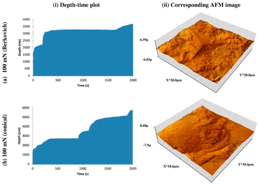
4.2. Depth vs. Time Curve and Film-Substrate Failure Behavior

During repeated loading cycle of impact, elastic stresses caused by the indenter (tensile around the indenter contact and compressive below the contact) can initiate film failure from pre-existing flaws or flaws induced by impact itself [10]. Similarly, during the unloading cycle, relaxation and mismatch in the indentation induced elastic stress field of film-substrate system can delaminate thin film from the substrate (Figure 9). Apart from film failure due to the elastic stress field [10] during repeated loading cycle of impact, a pre-existing residual stress (e.g., compressive in the TiNi film) can strongly affect mechanical performance (such as fatigue strength, delamination, fracture toughness and wear resistance) which influences the reliability and lifetime of components. It is anticipated that the impact loading stress can trigger the delamination when the film contains compressive residual stress. After the residual compressive stress in the film is released, film delamination can occur along the interface due to mismatch of the interfacial strain [14,15,29].
It is worth noting that the depth vs. time curve shows a forward depth deviation during the early stage of impacts. For each impact, the absorbing energy will be different due to degradation of materials (indicated by change in impact depths) in the contact and subsurface zone. After attaining a critical mismatch in the interfacial strain, the depth vs. time curve shows a backward depth deviation during the later stage of impacts. This is contrary to the expected behavior where contact depth should increase with the number of stress cycles [8,9,11]. Based upon the observations discussed above related to depth vs. time (and shown in Figure 3Figure 6), the film-substrate behavior during nano-impact (low-cycle fatigue) for both the indenters can be summarized as: (a) forward depth increases leading to plastic deformation or cracking in the thin film and substrate, (b) mismatch in the interfacial strain leading to thin film delamination or cracking from the substrate, and (c) depth decreases due to backward depth deviation (Type I or II) in the delaminated thin film (Figure 9).
It can be appreciated from the above discussion that the occurrence of backward depth deviation was load dependent. This was due to the changes in the location of subsurface shear stress with load. At loads lower than 1 mN, the behavior during impact will be determined by the film properties, hence only forward deviation was observed at a lower load of 1 mN. However at loads of 1 mN and 10 mN, properties of the film-substrate interface will dictate the nano-impact (fatigue) response and hence backward deviation was observed for measurements in these loads due to the dominant role of shear stress and film delamination near the film-substrate interface. Higher loads of 100 mN indicate a response dominated by the substrate and hence only forward depth deviation is observed.
Figure 10. SEM image of nano-impact (Berkovich) residual impression on amorphous NiTi film surface at 100 mN.
Coatings 02 00195 g010

4.3. Fatigue Performance of TiNi Thin Film and Future Prospects

Fatigue of TiNi films has always been a concern in the development of TiNi thin films for various applications [1]. The fatigue performance of TiNi thin films are influenced by a complex combination of internal (alloy composition, lattice structure, precipitation, defects, film-substrate interface) and external parameters (thermo-mechanical treatment, applied maximum stress, stress and strain rate, the amplitude of temperature cycling frequency) after long term thermal-mechanical cycles [1]. The high damping capacity exhibited by the TiNi films is of great importance to nanoscale devices, where the minimization of vibration and noise during operation at high speeds or due to impact loading is critical to the device performance [30]. The absence of a permanent residual impression on the TiNi film surface after final (1000th impact for lower loads such as 0.5 mN, 1 mN and 10 mN) unloading of the indenter might indicate that irreversible deformation due to either the nucleation or movement of dislocations or possible amorphization in the TiNi film did not occur [30] during nano-impact, however further investigation is required. This pseudoelastic behavior demonstrates the intrinsic capability of the TiNi films to undergo a large deformation without permanent surface damage, a phenomenon resembling the self-healing effect observed in previous studies (e.g., [30,31]). However, significant damage to the film-substrate system at high load impact (at 100 mN, depth vs. time curve, Figure 6) reveals that the impact energy was dissipated significantly.
The current investigation on nano-impact behavior of nitinol (amorphous) thin film can be benchmarked representing no shape memory property; however, further studies are being carried out by the authors to compare with the nano-impact behavior of nitinol (crystallized) and functionally graded shape memory alloy films. Considering different types of failure performance during nano-impact test, a nitinol thin film with higher adhesive strength to the substrate and a controlled pre-existing residual stress is required for durability of coated components. Also, such nanomechanical test can be used to obtain a better understanding of the localized contact fatigue performance and wear mechanism in various thin films.

5. Conclusions

The main conclusions drawn are as follows:
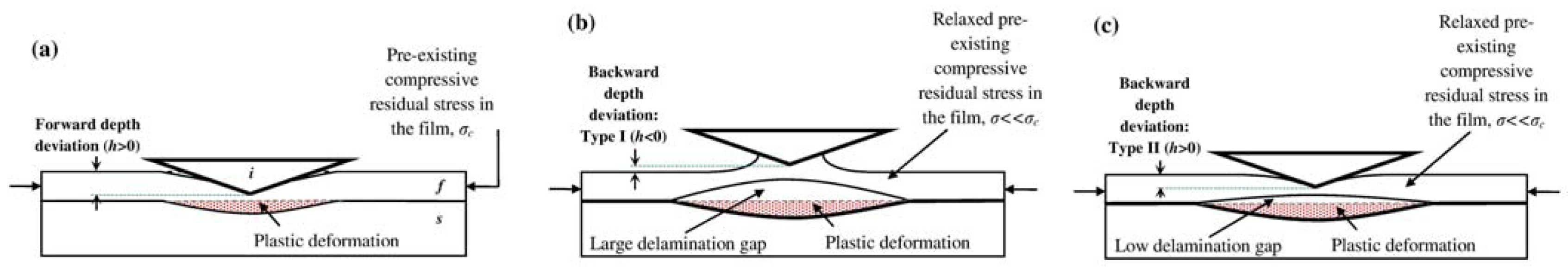
  • (a) Based on the indenter contact depth deviation data, two types of film failure mechanisms are proposed. The failure of films starts from delamination at the film-substrate interface, resulting in a decrease in contact depth (backward depth deviation), whereas, a typical increase in contact depth (forward depth deviation) with number of fatigue cycles was also recorded.
  • (b) Two types of backward depth deviation were observed for Berkovich and conical indenter. Type I indicates that the final impact depth is below zero, corresponding to a large film delamination gap; whereas, Type II indicates that the final impact depth is above zero, indicating a low film delamination gap.
  • (c) The delamination failure indicated release of elastic stored energy (residual stress), and can be indicated through peculiar decrease in contact depth for Berkovich and conical indenters.
  • (d) Indenter shape and nano-impact load had little influence on the type (forward or backward) of depth deviations.

References

  1. Fu, Y.Q.; Du, H.; Huang, W.; Zhang, S.; Hu, M. TiNi-based thin films in MEMS applications: A review. Sens. Actuat A 2004, 112, 395–408. [Google Scholar] [CrossRef]
  2. Pelton, A.R. Nitinol fatigue: A review of microstructures and mechanisms. J. Mater. Eng. Perform. 2011, 20, 613–617. [Google Scholar] [CrossRef]
  3. Pelton, A.R.; Schroeder, V.; Mitchell, M.R.; Gong, X.-Y.; Barney, M.; Robertson, S.W. Fatigue and durability of Nitinol stents. J. Mech. Behav. Biomed. Mater. 2008, 1, 153–164. [Google Scholar] [CrossRef]
  4. Miyazaki, S.; Ishida, A. Martensitic transformation and shape memory behavior in sputter-deposited TiNi-base thin films. Mat. Sci. Eng. A 1999, 273–275, 106–133. [Google Scholar] [CrossRef]
  5. Krulevitch, P.; Lee, A.P.; Ramsey, P.B.; Trevino, J.C.; Hamilton, J.; Northrup, M.A.M.A. Thin film shape memory alloy microactuators. J. Microelectromech. Syst. 1996, 5, 270–282. [Google Scholar]
  6. Fu, Y.Q.; Du, H.J.; Zhang, S. Curvature Method as a Tool for Shape Memory Effect. In Surface Engineering: Science and Technology II, Symposium at TMS 2002 Annual Meeting, TMS, Seattle, WA, USA, 17–21 February 2002; Kumar, A., Chung, Y.W., Moore, J.J., Doll, G.L., Yahi, K., Misra, D.S., Eds.; pp. 293–303.
  7. Faisal, N.H.; Ahmed, R.; Fu, Y.Q. Nano-Impact Testing and Failure Mechanism of Solar Panel DLC Film. In Proceedings of the Advanced Materials Technologies Conference (AMTC’11), Riyadh, Saudi Arabia, 17–19 October 2011; King Abdulaziz City for Science and Technology: Riyadh, Saudi Arabia, 2011; pp. 36–44. [Google Scholar]
  8. Beake, B.D.; Garcia, M.J.I.; Smith, J.F. Micro-impact testing: A new technique for investigating fracture toughness. Thin Solid Films 2002, 398–399, 438–443. [Google Scholar]
  9. Beake, B.D.; Lau, S.P.; Smith, J.F. Evaluating the fracture properties and fatigue wear of tetrahedral amorphous carbon films on silicon by nano-impact testing. Surf. Coat. Technol. 2004, 177–178, 611–615. [Google Scholar]
  10. Faisal, N.H.; Ahmed, R.; Reuben, R.L. Indentation testing and its acoustic emission response: Applications and emerging trends. Int. Mater. Rev. 2011, 56, 98–142. [Google Scholar]
  11. Li, X.D.; Bhushan, B. Development of a nanoscale fatigue measurement technique and its application to ultrathin amorphous carbon coatings. Scr. Mater. 2002, 47, 473–479. [Google Scholar] [CrossRef]
  12. Bhushan, B.; Li, X. Nanomechanical characterization of solid surfaces and thin films. Int. Mater. Rev. 2003, 48, 125–164. [Google Scholar] [CrossRef]
  13. Bhushan, B. Nanotribology and nanomechanics. Wear 2005, 259, 1507–1531. [Google Scholar] [CrossRef]
  14. Faisal, N.H.; Ahmed, R.; Fu, Y.Q.; Elakwah, Y.O.; Alhoshan, M. Influence of indenter shape on DLC film failure during multiple load cycle nanoindentation. Mater. Sci. Technol. 2012. Available online: http://dx.doi.org/10.1179/1743284712Y.0000000039.
  15. Ahmed, R.; Fu, Y.Q.; Faisal, N.H. Fatigue at nanoscale: An integrated stiffness and depth sensing approach to investigate the mechanisms of failure in diamond-like carbon film. J. Tribol. 2012, 134, 012001. [Google Scholar]
  16. Fu, Y.Q.; Du, H.J.; Zhang, S.; Ong, S.E. Effects of silicon nitride interlayer on phase transformation and adhesion of TiNi films. Thin Solid Films 2005, 476, 352–357. [Google Scholar] [CrossRef]
  17. Fu, Y.Q.; Du, H.J.; Zhang, S. Functionally graded TiN/TiNi shape memory alloy films. Mater. Lett. 2003, 57, 2995–2999. [Google Scholar] [CrossRef]
  18. Fu, Y.Q.; Du, H.J.; Zhang, S. Deposition of TiN layer on TiNi thin films to improve surface properties. Surf. Coat. Technol. 2003, 167, 129–136. [Google Scholar] [CrossRef]
  19. Fu, Y.Q.; Zhang, S.; Wu, M.J.; Huang, W.M.; Du, H.J.; Luo, J.K.; Flewitt, A.J.; Milne, W.I. On the lower thickness boundary of sputtered TiNi films for shape memory application. Thin Solid Films 2006, 515, 80–86. [Google Scholar] [CrossRef]
  20. Huang, W.; Pellegrino, S.; Bashford, D.P. Materials and Mechanical Testing. In Proceedings of the Conference on Spacecraft Structures, Noordwijk, The Netherlands, 27–29 March 1996.
  21. Faisal, N.H.; Ahmed, R. A review of patented methodologies in instrumented indentation residual stress measurements. Recent Pat. on Mech. Eng. 2011, 4, 138–152. [Google Scholar] [CrossRef]
  22. Faisal, N.H.; Steel, J.A.; Ahmed, R.; Reuben, R.L. The use of acoustic emission to characterize fracture behavior during Vickers indentation of HVOF thermally sprayed WC-Co coatings. J. Therm. Spray Technol. 2009, 18, 525–535. [Google Scholar] [CrossRef]
  23. Faisal, N.H.; Reuben, R.L.; Ahmed, R. An improved measurement of Vickers indentation behaviour through enhanced instrumentation. Meas. Sci. Technol. 2011, 22. [Google Scholar]
  24. Li, X.D.; Bhushan, B. Micro/nanomechanical and tribological studies of bulk and thin-film materials used in magnetic recording heads. Thin Solid Films 2001, 398, 313–319. [Google Scholar] [CrossRef]
  25. Bull, S.J. Nanoindentation of coatings. J. Phys. D Appl. Phys. 2005, 38, R393–R413. [Google Scholar] [CrossRef]
  26. Lawn, B.R.; Cook, R.F. Probing material properties with sharp indenters: A retrospective. J. Mater. Sci. 2012, 47, 1–22. [Google Scholar] [CrossRef]
  27. Drory, M.D.; Hutchinson, J.W. Measurement of the adhesion of a brittle film on a ductile substrate by indentation. Proc. R. Soc. London Ser. A 1996, 452, 2319–2341. [Google Scholar]
  28. Cordill, M.J.; Bahr, D.F.; Moody, N.R.; Gerberich, W.W. Recent development in thin film adhesion measurement. IEEE Trans. Device Mater. Reliab. 2004, 4, 163–168. [Google Scholar] [CrossRef]
  29. Raju, T.D.; Nakasa, K.; Kato, M. Relation between delamination of thin films and backward deviation of load-displacement curves under repeating nanoindentation. Acta Mater. 2003, 51, 457–467. [Google Scholar] [CrossRef]
  30. Ma, X.-G.; Komvopolous, K. Nanoscale pseudoelastic behavior of indented titanium-nickel films. Appl. Phys. Lett. 2003, 83, 3773–3775. [Google Scholar] [CrossRef]
  31. Kumar, A.; Kaur, D. Nanoindentation and corrosion studies of TiN/NiTi thin films for biomedical applications. Surf. Coat. Technol. 2009, 204, 1132–1136. [Google Scholar] [CrossRef]

