3.1. Film Topography and Microstructure
The microstructure and surface topography of the single layer CrN and multilayer Cr-CrN coatings on CFC substrates is shown in
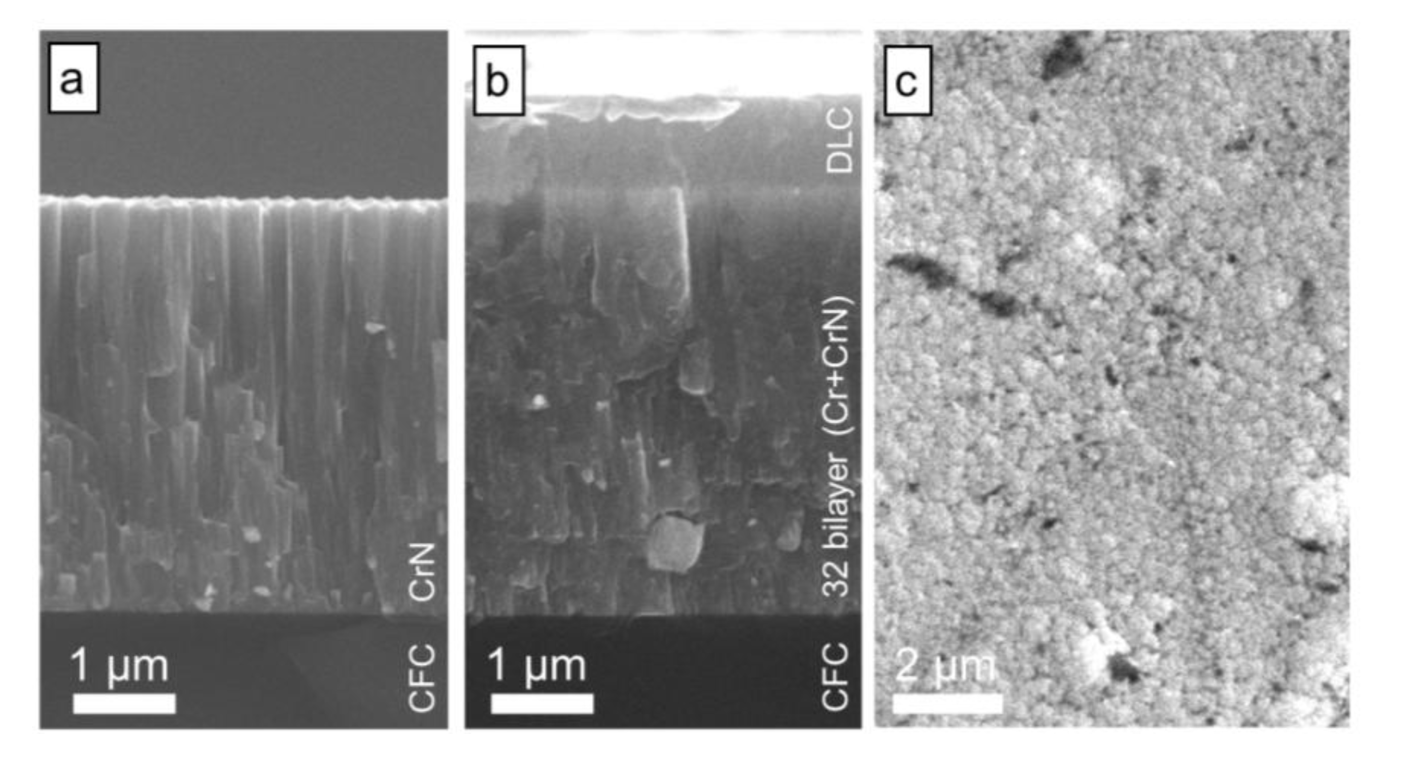
Figure 1. The CrN single layer coating in
Figure 1a reveals a columnar structure of tapered crystals and fibrous grains in the cross-section, which is assigned to the “Zone 1” structure in the Thornton structure model [
23]. This structure type is generally found for PVD coatings deposited at low temperatures and characterized by micro-cracks between the columns, pinholes, transient grain boundaries and through-coating porosity. This structure type merges at higher ion bombardment during deposition and thereby activated surface diffusion to a transition “Zone T” of fibrous grains with highly decreased porosity. Such refinement of grains is also visible for the multilayer Cr-CrN coating in
Figure 1b, although the ion bombardment is rather similar to the CrN single layer coating. However, the necessary renucleation at the Cr-CrN and CrN-Cr layer boundaries in the multilayer coating during growth has similar effects on structural refinement: It decreases grain size and, thus, porosity at loosely bond cone boundaries. As expected, the DLC layer on the top (
Figure 1b) is amorphous without distinct columnar growth features.
Figure 1.
Growth structure and surface topography of magnetron sputtered coatings grown on fiber reinforced epoxy composites (CFC): Scanning electron microscopy (SEM) cross-sections of (a) ~4 µm CrN single layer coating and (b) ~4 µm 32 bilayer (Cr + CrN) coating with ~1 µm diamond-like carbon (DLC) top layer; (c) SEM top view of the coating from (b).
Compared to well-known coating topographies on polished steel substrates (e.g., shown in [
24]) with fine spherical tops of the tapered crystallites, the topography of the coated CFC is much coarser and substantially different (
Figure 1c): This is due to the about 30 times higher surface roughness of CFC compared to steel, which decisively influences the growth morphology (compare also to detailed descriptions in [
10]) and reproduces the CFC substrate topography on the film surface. As visible with the decrease of Ra during the coating of CFC, the high roughness becomes smoother (
Table 1), decreasing the roughness for the 32 (Cr-CrN) bilayer coating on CFC to a value, which is only 10 times that for the similar coating on polished austenitic steel.
Table 1.
Arithmetic roughness (Ra) of uncoated substrates (carbon fiber reinforced epoxy composites (CFC), polished austenitic steel) and with deposited single layer and multilayer coatings.
Table 1.
Arithmetic roughness (Ra) of uncoated substrates (carbon fiber reinforced epoxy composites (CFC), polished austenitic steel) and with deposited single layer and multilayer coatings.
| Material/Coating | Roughness Ra [nm] |
|---|
| CFC | Steel |
|---|
| Uncoated substrate | 75.2 | 2.4 |
| CrN single layer | 59.0 | 6.4 |
| 16 bilayers (Cr-CrN) | 64.6 | 8.9 |
| 32 bilayers (Cr-CrN) | 68.2 | 6.7 |
| 32 bilayers (Cr-CrN) + 1 µm DLC | 109.3 | 15.1 |
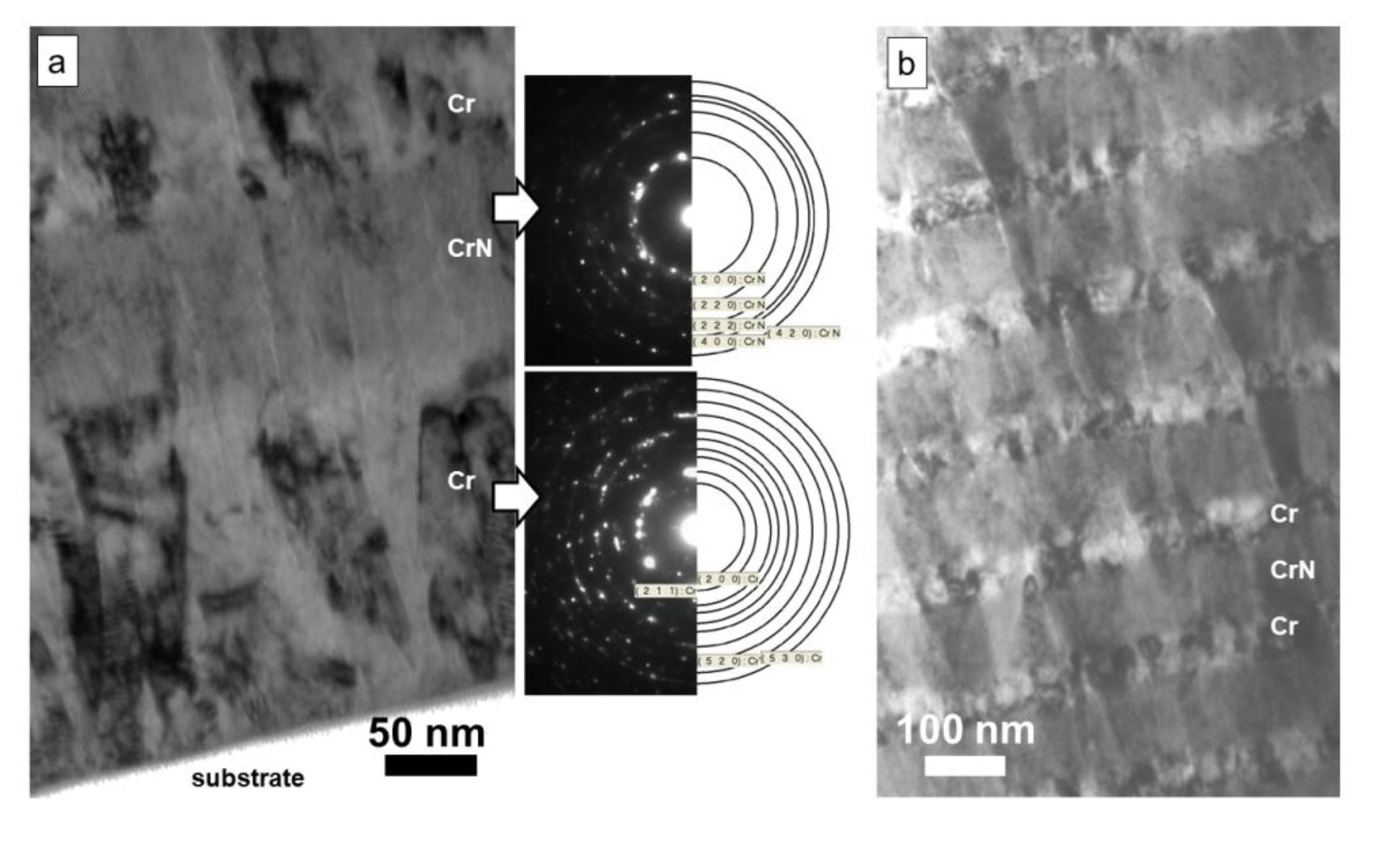
TEM imaging of the growth structures of the Cr-CrN multilayers on steel substrates reveals important effects dependent on the thickness of the individual layers of the multilayers (
Figure 2): The about 50% thicker Cr layer directly on the substrate surface shows much larger facetted, columnar and coarsened Cr grains than the second deposited thinner Cr layer after the first CrN layer (
Figure 2a), which was afterwards repeatedly used in the multilayer stack. In addition, the density of formed microcracks in between the grains is higher for the thicker Cr layer. As visible in
Figure 2b, no substantial coarsening in the subsequently deposited Cr-CrN multilayer occurs. The microcrack-like structures in the first Cr layer do not pass the interface to CrN and are only rarely found in the second Cr layer. Generally, the Cr grains were found to be larger (15–20 nm) than the CrN grains (5–10 nm size) (
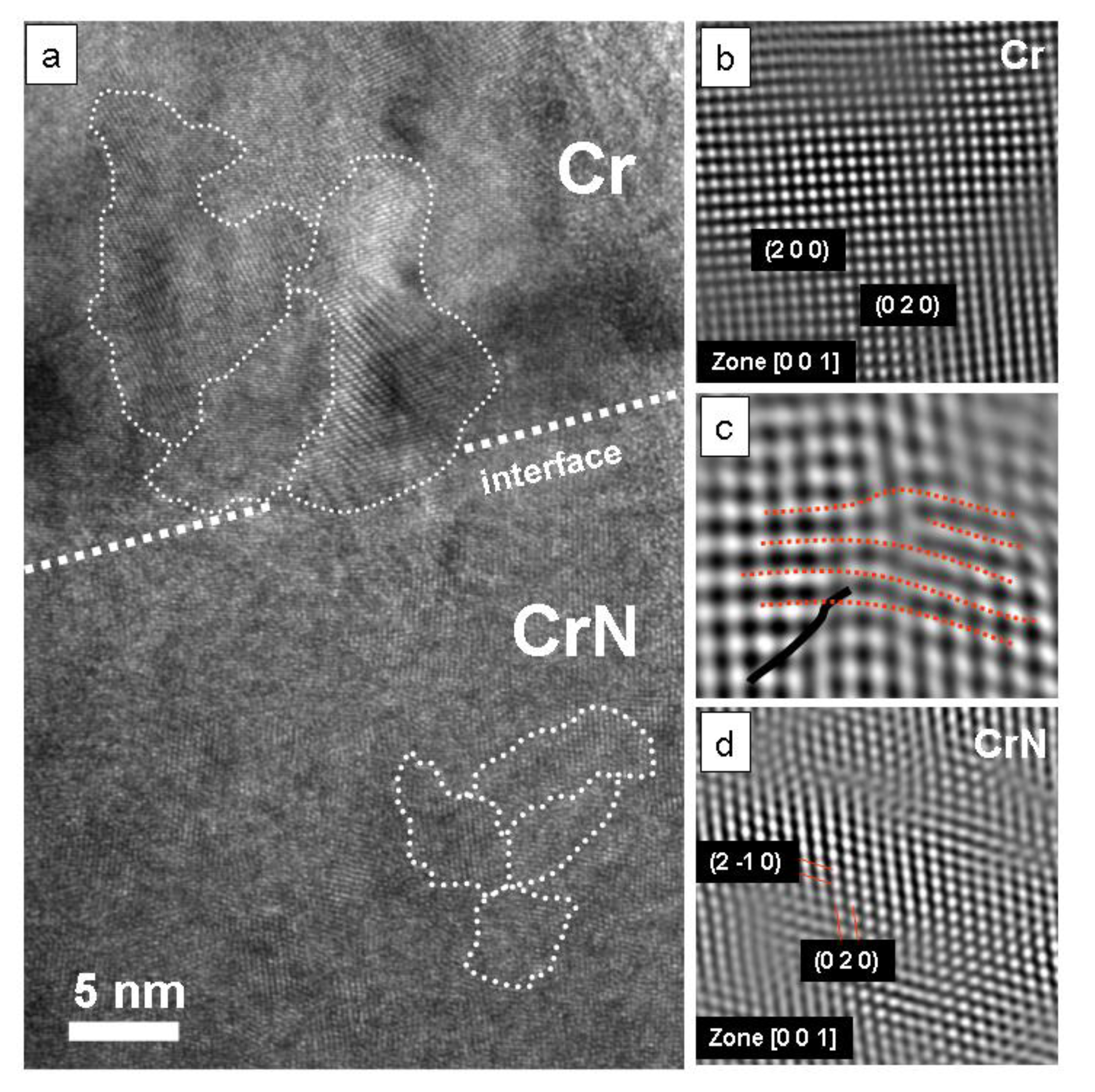
Figure 3a), although the Cr layers are thinner than the CrN layers (CrN/Cr ratio = 2:1). This seems to be due to the more complex fcc CrN structure (two overlapping NaCl lattices for Cr and for N) compared to single atom bcc Cr structure [
25]. Crystallographic dependence is evident at the interface: The small mismatch of lattice constants of CrN (
a = 4.14 Å) and Cr (
a = 4.588 Å) allows stress compensation during nucleation by introduction of step dislocations (
Figure 3c) in certain crystallographic orientations (e.g., (Cr (001) ║ CrN (001) and Cr [100] ║ CrN [110] [
26]) (
Figure 3b,d).
Figure 2.
Transmission electron microscopy (TEM) cross-section images of a 32 bilayer (42 nm Cr + 84 nm CrN) coating on steel substrate: (a) multilayer film growth behavior close to the interface to the substrate; (b) growth close to the coating surface.
Figure 2.
Transmission electron microscopy (TEM) cross-section images of a 32 bilayer (42 nm Cr + 84 nm CrN) coating on steel substrate: (a) multilayer film growth behavior close to the interface to the substrate; (b) growth close to the coating surface.
Figure 3.
High resolution mode (HR)-TEM cross-section images of the interface growth mechanisms of a 32 bilayer (42 nm Cr + 84 nm CrN) coating on steel: (a) Overview indicating the grain structure and grain sizes; (b) Crystallographic analysis of the Cr layer; (c) Interface growth with dislocation formation; (d) Crystallographic analysis of the CrN layer.
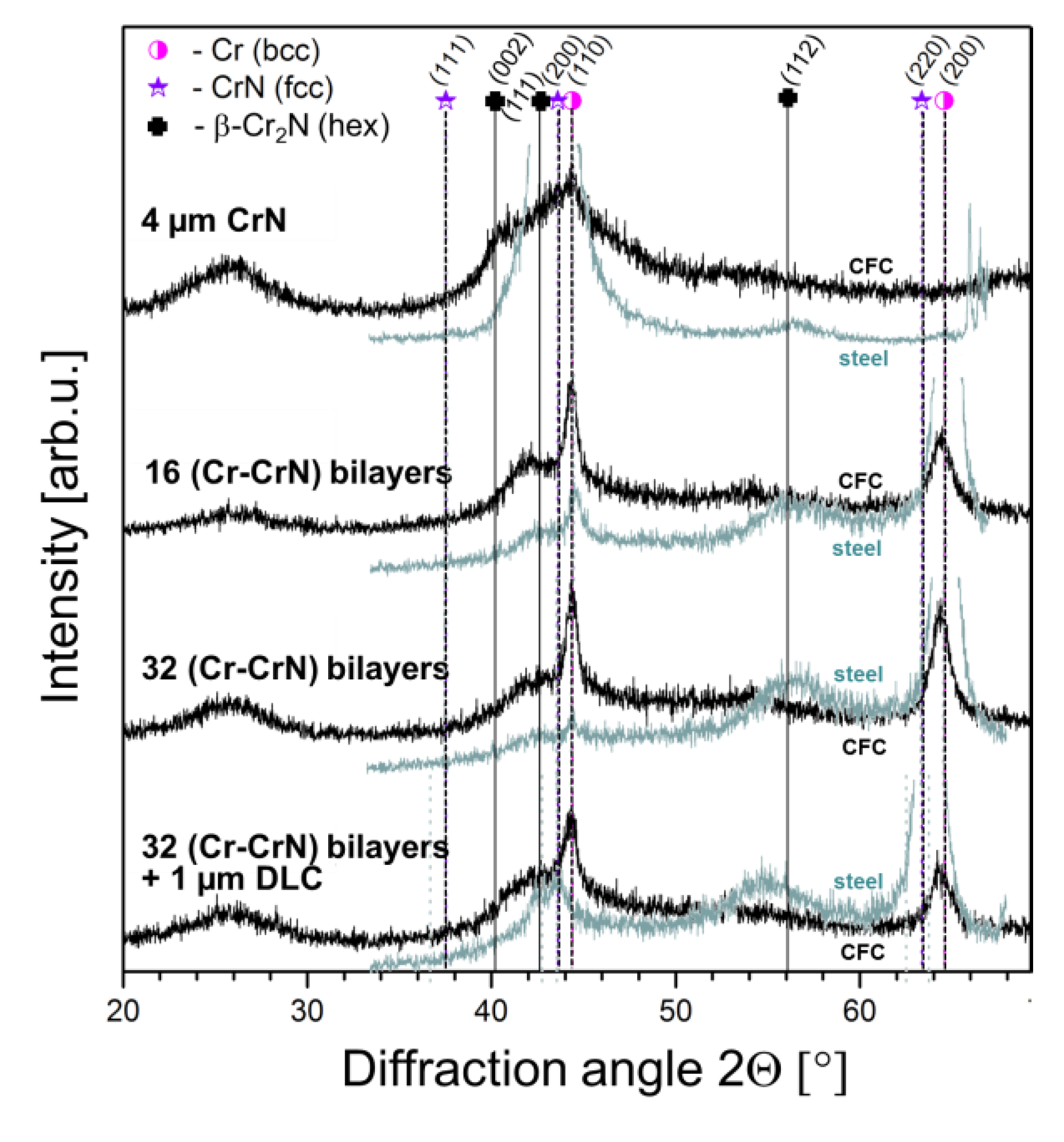
The XRD phase analysis in
Figure 4, comparing the coatings deposited on steel and CFC substrates, reveals high similarities in phases and orientations, although the substrate roughness is highly different: The Cr (200) peak of the coatings is more distinct on the steel than on the CFC substrate, which is connected to a higher phase content (higher crystallinity) and/or a larger Cr grain size. The peaks for all chromium nitride compounds (fcc CrN, hex β-Cr
2N [
25]) are rather weak for the multilayer coatings, but they dominate the XRD spectra of the single layer with the (200) CrN peak. Only weak and broad (nanocrystalline to amorphous) diffraction is present for the β-Cr
2N phase: Nevertheless, it is stronger in (112) orientation for coated steel, but in (111) and (002) orientation for coated CFC substrates. The Cr (110) peak is only found for the films on CFC, but missing for films on steel, as also revealed by the diffraction pattern of the Cr interface layer in
Figure 2a. The higher resolution in TEM diffraction patterns reveals further crystallographic phase features, not occurring in the XRD scans: strong (211) as well as weak (530) and (520) diffraction for Cr and weak (420) diffraction for CrN. The slight shift of the Cr (200) peak to lower diffraction angles could indicate tensile stresses in this phase.
Figure 4.
Locked-couple X-ray diffraction scan of single CrN layer and (Cr + CrN) multilayer coatings on CFC (black spectra) and on steel (grey spectra) including assignment of peaks to standard peak positions from Powder Diffraction File (ICDD) (Cr (bcc): 00-027-1402, CrN (fcc): 03-065-2899, β-Cr2N: 00-035-0803).
3.3. Deformation Mechanisms of the Coatings
The deformation mechanisms of coated CFC were studied by spherical indentation with high loads resulting in penetration depths of up to 7.5 µm. Such deep indents are necessary to trigger (visco-)elastoplastic flow of the epoxy matrix-rich CFC as well as deformation and fracture of the coating (top view in
Figure 5a, cross-section in
Figure 5b), if the yield or fracture strength is exceeded, respectively. Nevertheless, the influence of the deeper carbon fibers on surface deformation is only minor at these penetration depths in the epoxy layer.
FEM simulations of von-Mises stress distributions [
7] reveal highest stressed regions below the indenter center at the coating-substrate interface, but also outside the contact, due to bending of the layer with maximum tensile stress at the coating surface. This is graphically shown in
Figure 5c,d: The schematics in
Figure 5d describes the loaded region in the cross-section, while the effect of elastoplastic flow of material below the indent outside the contact area, resulting in circular and radial cracks of the bulged region, is schematically shown in
Figure 5c [
29,
30]: Ring cracks around the indent spread from the coating surface at the periphery of the contact and spread towards the substrate surface. Radial cracks in mild indentation with low local stress concentration (ball geometry, in contrast to pyramid-shaped indenters [
30]) mainly occur, if alternative fracture mechanisms at lower stresses for energy dissipation are missing and the circumferential tensile stresses become too high. In the investigated series of single and multilayer coatings, such radial cracks are only observed for the 32 bilayer Cr-CrN systems, both with and without the DLC top layer. Such Cr-CrN load bearing layers possess the highest elasticity index (
H/
E ratio) and, thus, may also dissipate deformation energy elastically.
Ring crack formation is the main failure mechanism for all other films. Brittle crack propagation may occur at the columnar grain boundaries along existing microcracks (compare to
Figure 2a) in the microstructure of the non-deformed materials due to the shear sliding of adjacent growth columns, which minimizes the shear loading [
31]. The TEM cross-section image in
Figure 5b shows the ring crack mode for a tough multilayer coating: Similar to preliminary investigations on the Ti-TiN multilayer coating system with soft Ti interlayers [
19], the introduction of soft metal layers (Cr) in CrN for Cr-CrN multilayer structures fully changes the micromechanics of the films: While the single layered hard coatings (TiN, CrN) would fail by cohesive fracture through the whole coating thickness, such ring cracks in a multilayered film can be deflected and can change the propagation direction. The transition from tensile to shear fracture in the 32 Cr-CrN bilayer coating, is clearly visible in two instances in
Figure 5b by the deflection of cracks from the direction normal to parallel to the substrate surface. After the deflection the crack propagation is arrested in the parallel shear crack.
Figure 5.
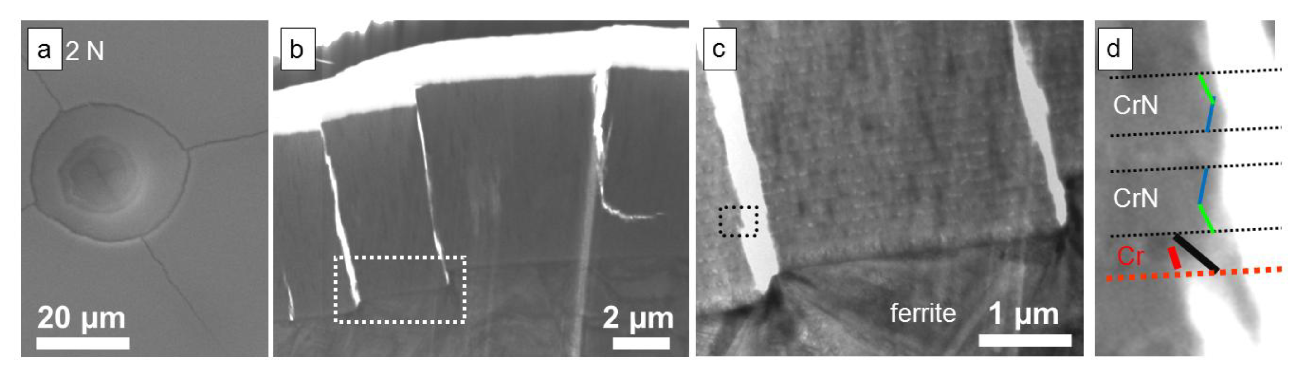
(a) SEM top view of an indent by 2 N loading of a spherical indenter in 32 bilayer (Cr + CrN) and 1 µm DLC top layer coated CFC; (b) TEM cross-section prepared by Focussed Ion Beam (FIB) from the marked position in (a) indicating deformation and fracture; (c) Schematics of formation of circular/ring cracks (σr) and radial cracks (σθ); (d) Schematics showing plastically deformed region under a ball indent in a coated compound and localization of crack initiation/formation.
Figure 5.
(a) SEM top view of an indent by 2 N loading of a spherical indenter in 32 bilayer (Cr + CrN) and 1 µm DLC top layer coated CFC; (b) TEM cross-section prepared by Focussed Ion Beam (FIB) from the marked position in (a) indicating deformation and fracture; (c) Schematics of formation of circular/ring cracks (σr) and radial cracks (σθ); (d) Schematics showing plastically deformed region under a ball indent in a coated compound and localization of crack initiation/formation.
In load-depth curves obtained in instrumented indentation experiments, any coating fracture is observed as kink: Our experiments showed that first cohesive coating failure occurs for the 32 bilayer multilayer coating at ~1.2 µm penetration depth (~100 mN load). For the single layer CrN coating as well as for the 16 bilayer coating, kink formation is found at much lower loads (<60 mN) and at only 0.75 µm penetration depth. In comparison, first kink formation for the 32 bilayer coating on stiffer, less compliant austenitic steel substrates is found at ~850 mN load (~2.8 µm penetration depth).
The differences of indentation micromechanics for coatings on soft and hard substrates are very apparent from the above results for very soft epoxy CFC surfaces (
E: 2–3 GPa,
H < 0.1 GPa) (
Figure 5) and stiffer substrate materials, e.g. austenitic steel (
E: 210 GPa,
H: 1.5 GPa) (
Figure 6): Higher load support by the steel substrate decreases total deformation and, thus, the crack density of both radial and ring cracks on the surface (
Figure 6a). Nevertheless, if the load bearing capacity of the coating is exceeded, fracture occurs and leads to localization of stresses on the substrate surface, which shear locally and introduces shear steps, which is well visible at the interface (
Figure 6b). As revealed by the small crack on the very left side of
Figure 6b, where crack propagation is stopped by the multi-layered architecture (interfaces), fracture in this investigated region starts from the interface. A distinct shear step is missing for this very small cracking event, because the stopped crack propagation prevented sliding of the crack flanks. Nevertheless, tensile stresses on the coating surface at higher distance to the indentation center also cause ring-like cracks after high substrate deformation (
Figure 6a). These ring cracks are partly deflected to shear cracks (
Figure 6b, on the very right). The detail at the crack flank in
Figure 6c and under high resolution in
Figure 6d show in detail the mechanism of crack stopping in the multilayer: Shear deformation of the coating is concentrated in 45° planes of Cr layers, while the CrN layers show brittle fracture (fracture normal to the substrate surface).
Figure 6.
Deformation behaviour of Cr-CrN multilayer coatings with 32 bilayers (CrN:Cr ratio = 2:1), deposited on austenitic steel and substrates. (a) Surface topography after indentation with 2 N load; (b) TEM cross-section of the deformed/fractured indent site; (c,d) Details of deformation and fracture as marked in (b) and (c).
Finally, the comparison of the micromechanical results with data obtained from scratch testing reveal for all coatings high adhesion on all substrate materials, while the cohesion of the coating is mainly dependent on the used layer architecture and the substrate type (mechanical behavior): Cohesive coating failure is present for the multilayer coated CFC at critical load Lc1~0.5 N and for austenitic steel at ~1 N. Adhesive failure (Lc2) is missing for all systems even at maximum load of the scratch tester (30 N) and for ~50 µm deformation depth.
3.4. Tribological Behavior of Coated CFC
Strains in tribological contacts are generally highly dynamical and fatigue plays an important role, even below the static yield strength. In coated systems, the compliance of the substrate decisively influences friction and wear, because bending both below and around the contact area introduces alternating tensile and compressive stresses in the substrate surface and coating. In the case of missing friction (friction coefficient µ = 0), the maximum von-Mises stress is ~35% higher for the case of a stiff coating layer (
E1) on an elastic substrate (
E2 = ½
E1) than in the non-coated case. However, friction plays a decisive role, affecting the tangential forces and, thus, the shear stresses in the coating-substrate system [
31]. In the theory of pure indentation or at zero friction (µ = 0), yielding in the coated surface always initiates at the coating/substrate interface below the center of the contact (highest von-Mises stresses), and the plastic zone does not grow towards the surface below the indenter [
32,
33]. Applying friction load (µ > 0), the point of first yield moves from the center position backwards or forwards, depending on the friction coefficient [
33]: For µ = 0.25, the highest stressed region moves closer to the surface compared to the non-coated case, being ~40% higher as non-coated and ~50% as coated surface and µ = 0. These values increase to ~65% and 125% for µ = 0.5, respectively.
Based on these theoretical simulation model results it is clear, that the superposition of large elastic deformation of the coated elastic substrate from normal loading and the friction induced shear loads easily leads to coating fracture and fatigue influenced phenomena like fragmentation and delamination, drastically influencing the tribological behavior.
Figure 7 and
Figure 8 show the evolution of friction coefficients in contact to Al
2O
3 and AISI 5210 steel counterpart balls in dependency of the contact lap number. For Al
2O
3 counterparts (
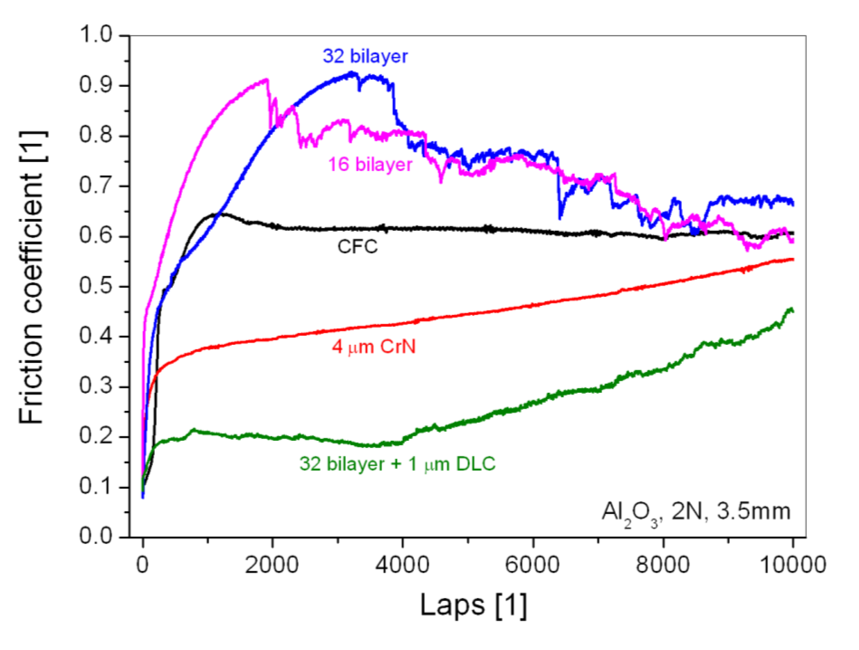
Figure 7), the friction coefficient of all coatings is initially very low (µ ~ 0.08). Ongoing sliding leads for the Cr-CrN multilayers to a sudden increase of friction up to 0.9, which slowly decreases to 0.6, which is the steady-state friction coefficient for uncoated CFC against Al
2O
3. In contrast, the friction for the pure CrN coating as well as the multilayer with DLC top layer steadily increases from the initial level of 0.1–0.6, which is the value for uncoated CFC. The friction for the contact to AISI 5210 steel (
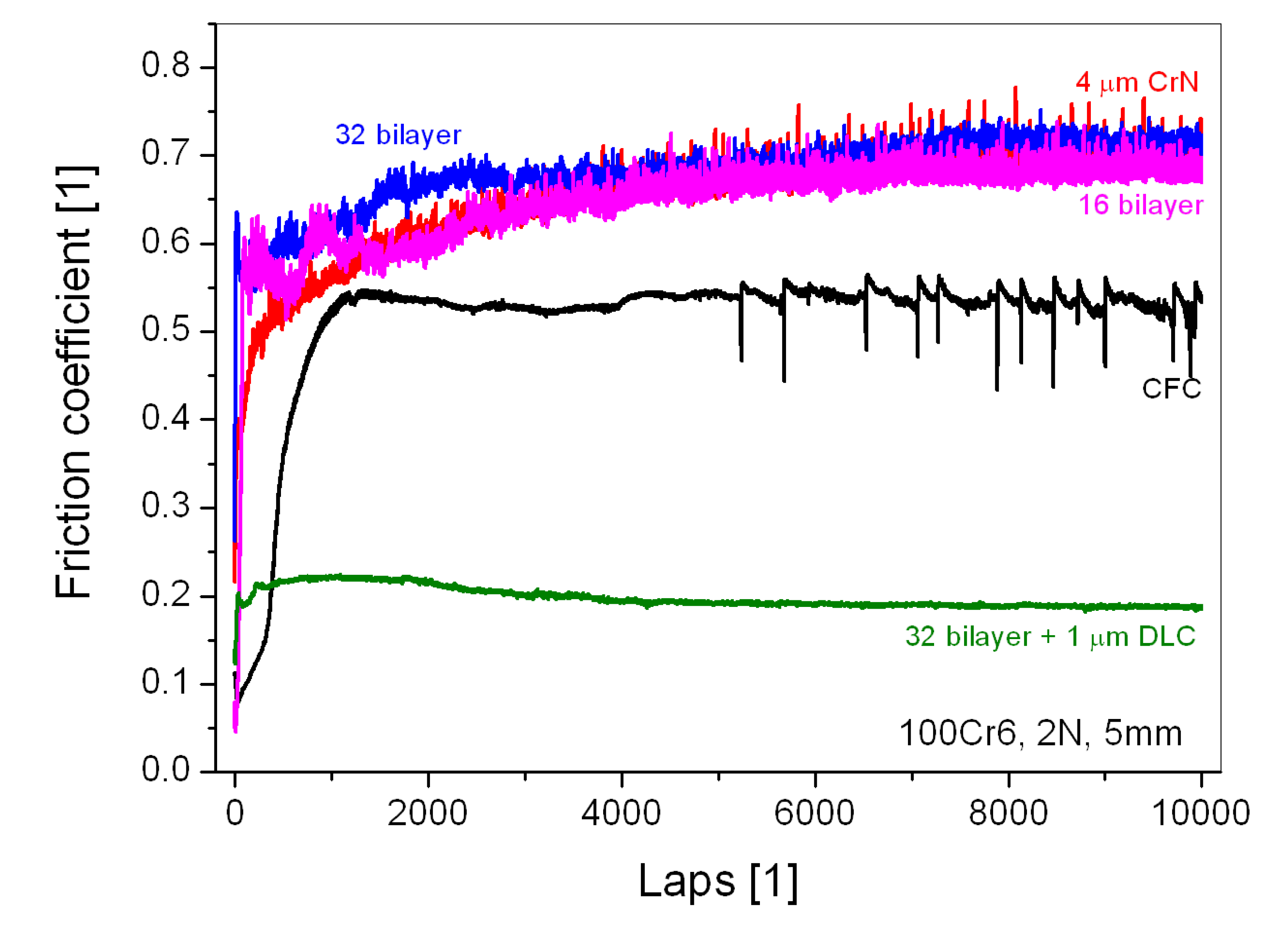
Figure 8) is initially lower, but after the run-in generally higher for the CrN-based coatings without a DLC top layer (µ > 0.65) than for the non-coated CFC substrate (µ ~ 0.5). Only the multilayer composition with the DLC top layer enables a lower steady-state friction (µ ~ 0.17) than is found for the non-coated contact, due to the well-known low friction coefficients of DLC-steel contacts.
A detailed analysis of the friction curves in
Figure 7 and
Figure 8 in combination with an analysis of the wear tracks in
Figure 9 and
Figure 10 is essential to understand the tribological mechanisms, which occur in sliding on the coated CFC surfaces: Based on friction stages proposed by Suh and Sin [
34] the initial very low friction is mainly a result of ploughing the softer surface by asperities, starting for the investigated coatings on CFC with µ = 0.08 and 0.045 for Al
2O
3 and steel counterparts, respectively. Based on the surface hardness, this ploughing mechanism by asperities occurs in contact to Al
2O
3 on the softer coating surface, but oppositely on the steel ball surface for this tribological contact. Although the mechanisms occurring in the initial friction contact were not investigated in this work, mechanisms occurring in later stages (mainly the transfer layer formation) indicate such behavior. Nevertheless, the high waviness and roughness of the coated CFC (see
Table 1) enhances this low friction mechanism.
Repeated cyclic ploughing deformation quickly results in low-cycle fatigue fracture of asperities, leading to the next stage in the frictional contact. Both plastic deformation and fracture at high stresses contribute to smoothing and polishing the wear track, whereby wear debris is trapped in grooves. Additionally, cyclic deformation occurs inside and around the contact area due to the high compliance of the epoxy matrix of the substrate. Radial and ring cracks form during overloading, shown by the static indentation experiments above. These cohesive cracks and their propagation to adhesive cracks and coating delamination contribute additionally to the specific behavior of sliding on coated CFC surfaces.
As visible in
Figure 7 and
Figure 8, the friction coefficient rapidly increases to >0.5 for the Cr-CrN multilayer coatings for both contact to Al
2O
3 and steel counterparts after the short run-in period, while friction coefficient for the CrN single layer hard coating in contact to Al
2O
3 as well as the coating types with DLC top layer are generally below the values for contact to uncoated CFC. The origin of this different behavior is the immediate formation of wear particles in sliding. Ploughing by wear particles results in high shear forces and, thus, high friction coefficients especially for coatings with the ability to shear like the multilayers with plastically deformable Cr layers. These particles are entrapped between the sliding surfaces and may form deformable and sticky transfer layers (tribolayers), which represent the steady-state condition of friction. The friction coefficients remain constant till the substrate is exposed e.g., by ploughing by the formed wear particles or delamination of the coating from the substrate surface whereby the coating finally failed.
Figure 7.
Friction coefficients depending on the lap number (# contact cycles) for the tribological contact of an Al2O3 ball (6 mm) in ball-on-disk testing with uncoated and single and multilayer coated CFC under 2 N load and 3.5 mm wear track diameter (10,000 laps = 110 m sliding of pin).
Figure 7.
Friction coefficients depending on the lap number (# contact cycles) for the tribological contact of an Al2O3 ball (6 mm) in ball-on-disk testing with uncoated and single and multilayer coated CFC under 2 N load and 3.5 mm wear track diameter (10,000 laps = 110 m sliding of pin).
Figure 8.
Friction coefficients depending on the lap number (# contact cycles) for the tribological contact of a DIN 100Cr6 / AISI 5210 steel ball (6 mm) in ball-on-disk testing with uncoated and single and multilayer coated CFC under 2 N load and 5 mm wear track diameter (10,000 laps = 157.1 m sliding of the pin).
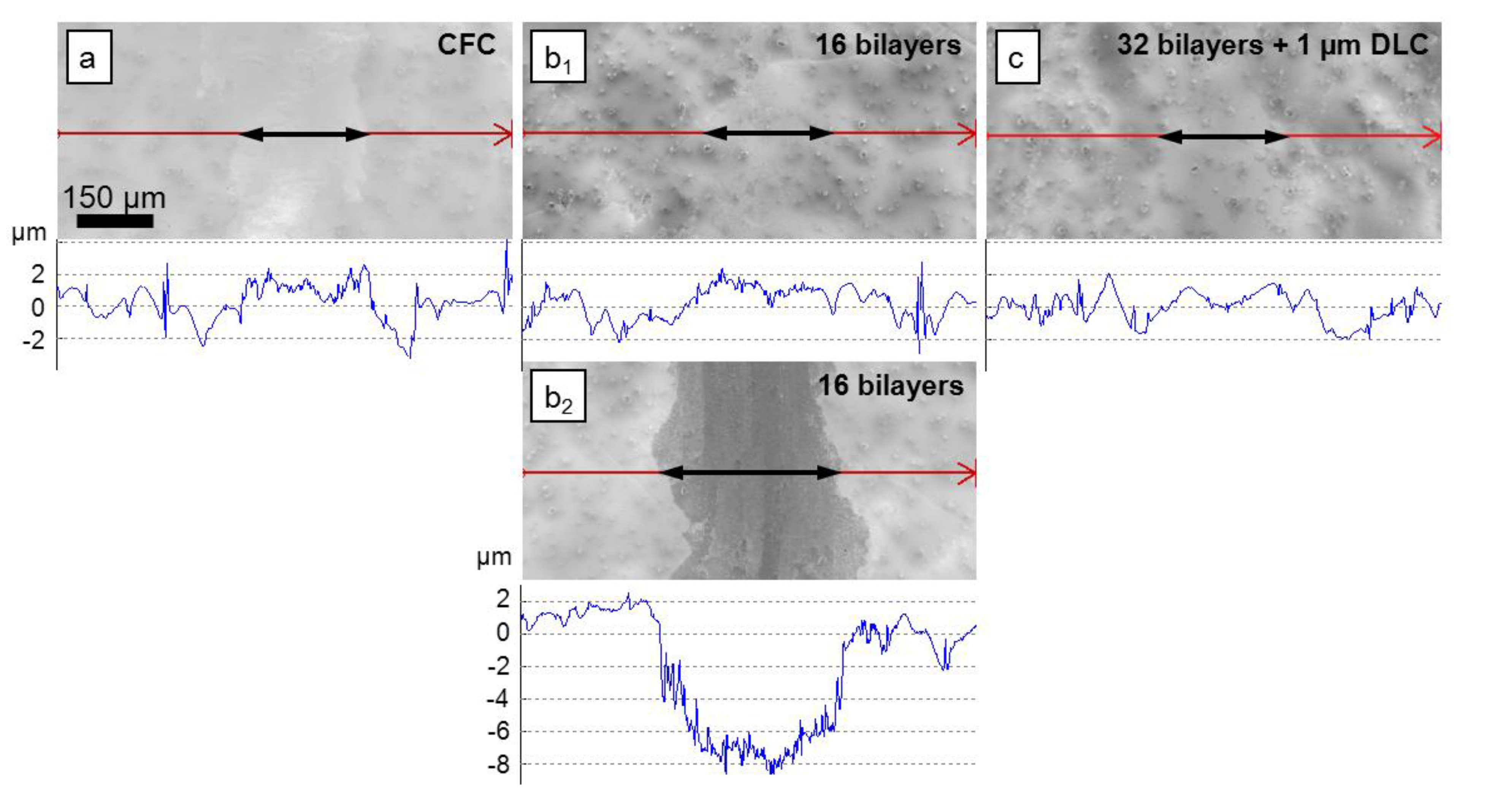
Figure 9.
Light microscopy images and optical profilometry scans of the wear track after ball-on-disk testing with an Al
2O
3 ball (for experimental details see
Figure 7) on (
a) uncoated CFC; (
b) CFC coated with 16 bilayers (Cr-CrN) (
b1: undamaged coating with transfer layer,
b2: highly abraded coating and substrate, both found on the same wear track); and (
c) CFC coated with 32 bilayers (Cr + CrN) and 1 µm DLC top layer. The long arrows indicate the profilometry scan lines, the short bold arrows the approximate width of the wear tracks.
Cr-CrN multilayer coating contacts to Al
2O
3 counterparts show very high friction coefficients of up to 0.94 in this steady-state regime (
Figure 7). However, the shearing of metal Cr under cyclic loading, fatigue fracture, the formation of abrasive wear debris and transfer layer adhesion on the Al
2O
3 counterpart due to sticky wear debris results in quick partial failure of the coating (
Figure 9b), baring the substrate surface. Transfer of epoxy polymer from these areas forms polymeric transfer layers (based on SEM EDS analysis) at the whole wear scar on ball and disc, which decreases the friction significantly. During sliding, frictional heat may chemically modify the bared polymer and the polymer transfer layers (introduction of atoms from ambient atmosphere, cross-linking and polymer chain scissoring,
etc. [
35]). The formation of a thick tribolayer (transfer layer) on the uncoated CFC indicates such a mechanism as the main contribution in the tribological behavior for contact to Al
2O
3 (
Figure 9a). The repeated sudden changes of the friction coefficient during on-going sliding for the Cr-CrN multilayer coatings (
Figure 7) indicate furthermore stepwise delamination and new formation of transfer layers.
The single layer CrN behaves differently in tribological contact to Al
2O
3 due to lack of shearing at softer Cr layers and lower adhesion of transfer layers of the worn coating on the counterpart. Furthermore, cracking in the coating around the contact area runs generally through the whole film thickness during overloading, whereby large coating fragments delaminate. This process starts very early after the run-in period, which is visible by a partly bared CFC substrate surface in the wear track. Missing adhesion of transfer layers on the Al
2O
3 keep the friction coefficient low. Nevertheless, ongoing grinding wear of CrN wear debris increases bared CFC substrate surfaces in the wear track and increases the friction coefficient towards the value measured for sliding of Al
2O
3 on uncoated CFC (
Figure 7). Finally, wear of the partly bared substrate surface contributes to a transfer layer formation on both the CrN as well as on the counterpart.
In sliding of AISI 5210 counterparts on CrN and Cr-CrN coatings, a thick transfer layer is generally formed in the steady-state stage by mechanical mixing on the top of the CrN surface (
Figure 10b,c). Based on SEM EDS analysis, this transfer layer consists of Fe, Cr, N, O and hydrocarbons. Its formation is mainly due to asperity fatigue mechanisms, in which the harder coating wears the softer steel counterpart. Nevertheless, the asperity fracture and coating delamination/spallation mechanisms do not stop after formation of the transfer layer, which is visible in the deep grooves down into the CFC substrate in the depth profile of the 16 bilayer coating (
Figure 10b). In comparison, wear of uncoated CFC is mainly due to grinding by asperities of the much harder steel ball (
Figure 10a).
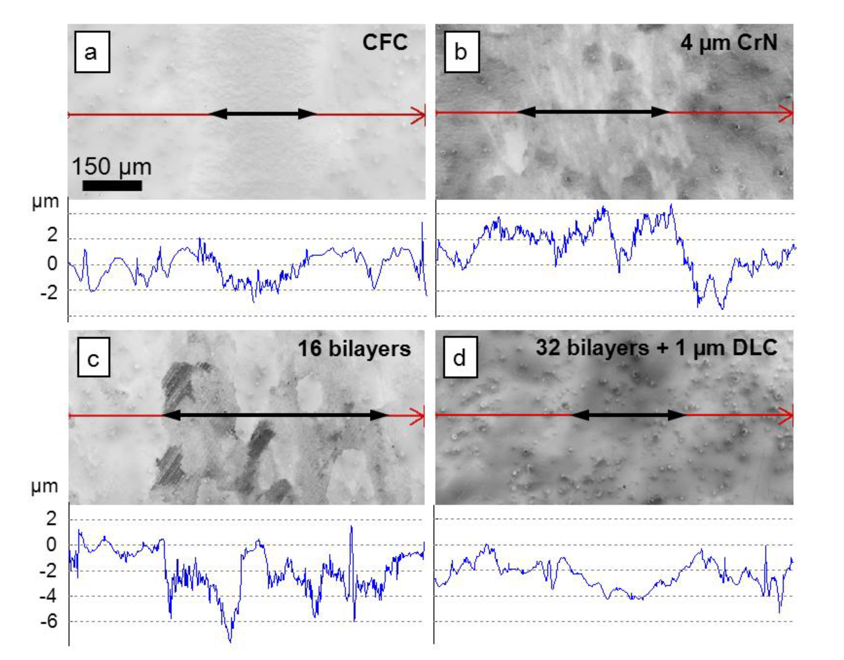
Figure 10.
Light microscopy images and optical profilometry scans of the wear track after ball-on-disk testing with a DIN 100Cr6 / AISI 5210 steel ball (for experimental details see
Figure 8) on (
a) uncoated CFC; (
b) CFC coated with ~4 µm CrN single layer coating; (
c) CFC coated with ~4 µm 16 bilayer Cr-CrN multilayer coating; and (
d) CFC coated with 32 (Cr + CrN) bilayers and a 1 µm DLC top layer. The long arrows indicate the profilometry scan lines, the short bold arrows the approximate width of the wear tracks.
Main tribological improvements can be achieved by low-friction DLC top layer both for the sliding of AISI 5210 steel and Al
2O
3 balls. The coated structure is not substantially damaged during the investigated sliding distance in all cases (
Figure 9c and
Figure 10d). This superior behavior is mainly due to the low friction coefficients and the decreased tribological stresses (low shearing component).


