1. Introduction
In modern gas turbines, plasma-sprayed thermal barrier coating (TBC) systems have been applied for several decades to improve performance. The thermally insulating layer can reduce the temperature of the metallic substrate, resulting in improved component durability. Furthermore, an improvement in efficiency can be achieved by permitting an increase of the turbine inlet temperatures. Thus, TBCs offer great benefits for the operation of gas turbine aircraft engines, gas turbine shipboard engines, and land-based industrial gas turbine engines [
1].
Such TBC systems are complex, multi-layered, and multi-material systems with many variants related to composition, processing, and microstructure. They consist of at least two layers—a bond coat layer and an insulating ceramic topcoat. The bond coat is often a metal, and has two major functions. It improves bonding between the substrate and the topcoat, and it protects the substrate from corrosion and oxidation. The ceramic topcoat provides heat insulation by its low thermal conductivity, resulting from bulk material characteristics as well as from microstructural features such as pores and voids [
2].
Partially yttria stabilized zirconia (YSZ) with 6 to 8 wt.% yttria content is frequently used as a TBC material due to its high thermal expansion coefficient and its relatively good fracture toughness. YSZ formed by Electron Beam-Physical Vapor Deposition (EB-PVD) or Atmospheric Plasma Spraying (APS) consists of a metastable
t′-phase. Upon prolonged exposure at elevated temperatures, it decomposes into high-yttria and low-yttria phases. The latter transforms upon cooling into the monoclinic phase, with an associated large volume increase; this may prove to be catastrophic, resulting in failure of the TBC [
3]. The accepted upper limit for use is 1200 °C. In addition to the limited phase stability, sintering also reduces the high-temperature capability, as it leads to a loss of strain tolerance of the coatings and hence early failure [
4].
These shortcomings have initiated many research activities seeking even better ceramics than YSZ [
5,
6]. In particular, several zirconate pyrochlores show low thermal conductivities and high thermal stabilities. Among them, lanthanum zirconate La
2Zr
2O
7 (LZ) is phase-stable to its melting point. At the same time, it displays a lower thermal conductivity (1.56 Wm
−1 K
−1, bulk material) and a lower sintering tendency when compared to YSZ. However, the thermal expansion coefficient of 9.1 × 10
−6 K
−1 (30–1000 °C) [
5] is low in relation to bond coats and Ni-base alloy substrates (~15 × 10
−6 K
−1), and the toughness is poor [
7]. For this reason, pyrochlores are applied in combination with YSZ in double-layer TBC systems [
8,
9,
10,
11]. YSZ is applied as the first ceramic layer, since TBC failure is often initiated by cracks occurring close to the bond coat. Furthermore, this YSZ interlayer can prevent possible reactions between the pyrochlore and the alumina-based scale (thermally-grown oxide, TGO) formed on the bond coat under thermal load [
12].
The La
2O
3∙ZrO
2 phase diagram shows a stable pyrochlore region up to the melting temperature of 2295 ± 10 °C, and the stability region ranges from approximately 33 to 35 mol % La
2O
3 at 1500 °C (La/Zr atomic ratio 0.99 to 1.08) [
13]. Due to the high fusion enthalpy of ~350 kJ mol
−1, solidification starts directly in the form of pyrochlore. However, considerable amounts of metastable fluorite phase are formed in the case of rapid solidification, which is typical of plasma spray conditions. This fluorite phase is transformed to pyrochlore at temperatures above 1000 °C. This is not critical, as this transformation is not associated with a significant volume change. However, the processing of LZ by APS is still challenging, because lanthanum is prone to evaporation in the plasma plume, resulting in non-stoichiometric coatings. La
2O
3 shows considerably higher vapor pressure compared to ZrO
2 [
14]; this problem was already investigated by Cao et al. [
12]. Later, the issue of the limited thermal stability of LZ again came up for discussion when new plasma torches, such as the three-cathode TriplexPro™-210 were applied, which are usually operated at elevated power levels. In [
15], it is reported that severe lanthanum evaporation can occur such that considerable amounts of undesired zirconia are formed. As this is non-stabilized, it is subjected to phase transformations during TBC operation, associated with significant changes of the specific volume.
In this work, the development and testing of LZ/YSZ double layer TBC systems is described. Initially, suitable basic parameters (torch, plasma gas composition, and power) were tested with respect to coating stoichiometry. Then, microstructures were optimized by adjusting feed rate, spray distance, and selecting a more appropriate feedstock. The microstructures of powder particles and coatings were characterized by digital image analysis.
2. Materials and Methods
2.1. Materials
Three experimental powders were used in this study (
Table 1). The particle size distributions of the feedstock powders were determined by laser diffraction (Horiba LA950, RETSCH Technology GmbH, Haan, Germany).
For coating development, stainless steel substrates were generally used. If freestanding coatings were needed for particular characterization methods (see
Section 2.2), coatings were sprayed on graphite substrates. For the thermal cycling tests, Inconel 738 LC substrates were used, having a diameter of 30 mm, and were 3 mm thick. The rims of the substrates were rounded off in order to avoid edge effects. Plasma spraying under a low pressure (LPPS) with a F4 gun was used to deposit NiCoCrAlY bondcoats (Metco AMDRY 386), being 150 µm thick. A commercially available 8YSZ powder (Metco 204 NS) was used for the first ceramic topcoat layer.
2.2. Methods
The samples were coated by APS in a Multicoat facility (Oerlikon Metco, formerly Sulzer Metco, Wohlen, Switzerland) with a three-cathode TriplexPro™-210 torch mounted on a six-axis robot. For both the 8YSZ and the LZ coatings, the 9 mm diameter nozzle was used with a 1.8 mm diameter feedstock injector. The standard plasma gas composition was 46 standard liters per minute (slpm) Ar and 4 slpm He. For 8YSZ, the current was 420 A, while for LZ, it was varied between 275 A and 450 A, yielding plasma torch input powers between 22 and 42 kW. To investigate the possible effect of hydrogen in the plasma gas, for LZ a composition of 40 slpm Ar and 10 slpm H2 was also applied at 275 A, corresponding to a torch power of 32 kW. Furthermore, a conventional one-cathode F4 gun was used for LZ, with a plasma gas mixture of 40 slpm Ar and 10 slpm H2 at 250 A and 620 A yielding torch powers of 23 kW and 41 kW, respectively; these were similar power levels as set for the TriplexPro™-210 torch. The spray distance was varied between 90 and 150 mm.
The coatings sprayed on graphite substrates were subsequently stripped by grinding. Parts of the freestanding coatings were used for chemical analysis by optical emission spectroscopy with inductively coupled plasma (ICP-OES). The remaining samples were investigated by X-ray diffraction analysis (XRD) and then embedded into epoxy resin to prepare metallographic polished cross sections for microscopic investigation and elemental analysis. XRD was performed on a D4 ENDEAVOR diffractometer (Bruker AXS GmbH, Karlsruhe, Germany), and scanning electron microscope (SEM) investigation on an Ultra55 model (Carl Zeiss NTS GmbH, Oberkochen, Germany) combined with an energy-dispersive X-ray INCAEnergy355 spectrometer (EDS, Oxford Instruments Ltd., Abingdon, Oxfordshire, UK). Digital Image Analysis was performed by AnalySIS pro 5.0, Olympus Soft Imaging Solutions GmbH, Münster, Germany.
Details on the thermal cycling test setup can be found in [
16]. The maximum surface temperature applied in this work was approximately 1400 °C, while the bondcoat temperatures were kept at approximately 1070 °C. Dwell times were 5 min for heating and 2 min for cooling.
3. Results and Discussion
3.1. Plasma Spray Parameter Selection
Initially, the effects of torch type, input power, and plasma gas composition on the coating stoichiometry were investigated.
Table 2 gives the plasma parameters and the corresponding results of the chemical analyses. In all cases, the 321 M powder was used with a feed rate of 8 g/min, and the spray distance was 90 mm.
The major influence on the coating stoichiometry is exerted by the torch power. At higher levels (450 A with TriplexPro™-210 and 620 A with F4), severe La depletion was observed in each case. The reason is the significantly higher vapor pressure of lanthania compared to zirconia. If the TriplexPro™-210 is operated with hydrogen as secondary plasma gas, the stoichiometry is also strongly affected. This is probably due to the high thermal conductivity of hydrogen in combination with the high torch efficiency. Moreover, it is noteworthy that the conventional one-cathode F4 gun still induces a slight La depletion, even in the case of low input power, while the three-cathode TriplexPro™-210 operated at the same power does not. It is suggested that this is achieved by the more stable operation with lower arc fluctuations of the latter.
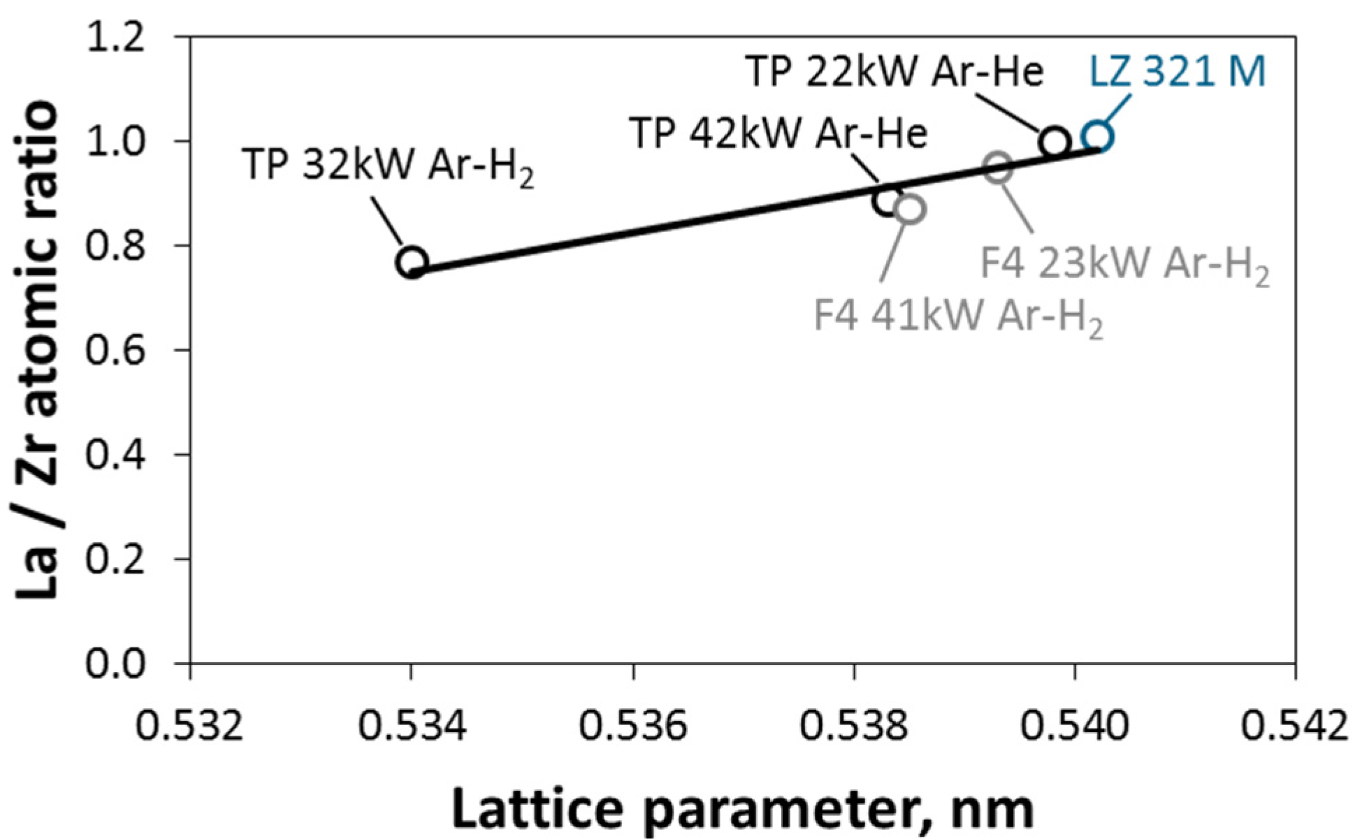
It is shown in [
15] that the stoichiometry of LZ coatings is well-reflected by the lattice parameter. In the as-sprayed state, LZ is obtained as a metastable fluorite with space group 225 (Fm-3m, cubic). La depletion leads to a decrease of the lattice parameter, which is well-correlated to the La/Zr atomic ratio determined by chemical analysis. In
Figure 1, this is shown for the as-sprayed samples given in
Table 2, as well as for the applied feedstock material 321 M.
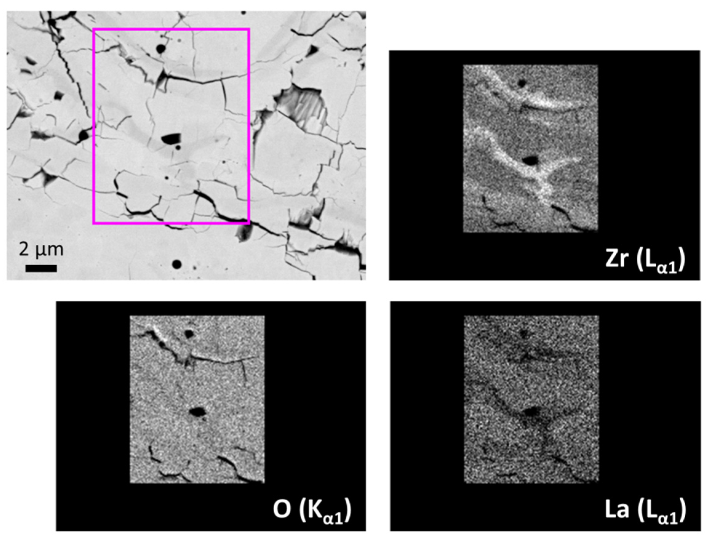
Figure 2 shows the EDS elemental mapping of a coating sprayed with TriplexPro™-210 at high power (42 kW) and with Ar–He plasma gas mixture. As already indicated by the different grey tones in the back-scattered electron image, the EDS results show a severe La depletion running along the splat structures. It is assumed that the La evaporation occurs mainly in-flight from the particle near-surface regions.
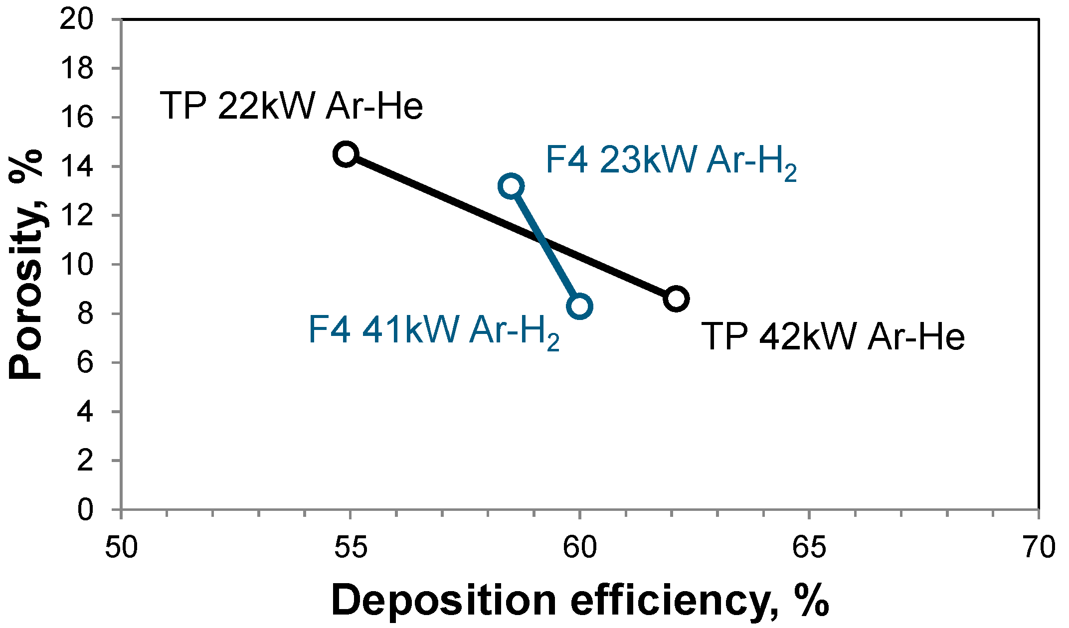
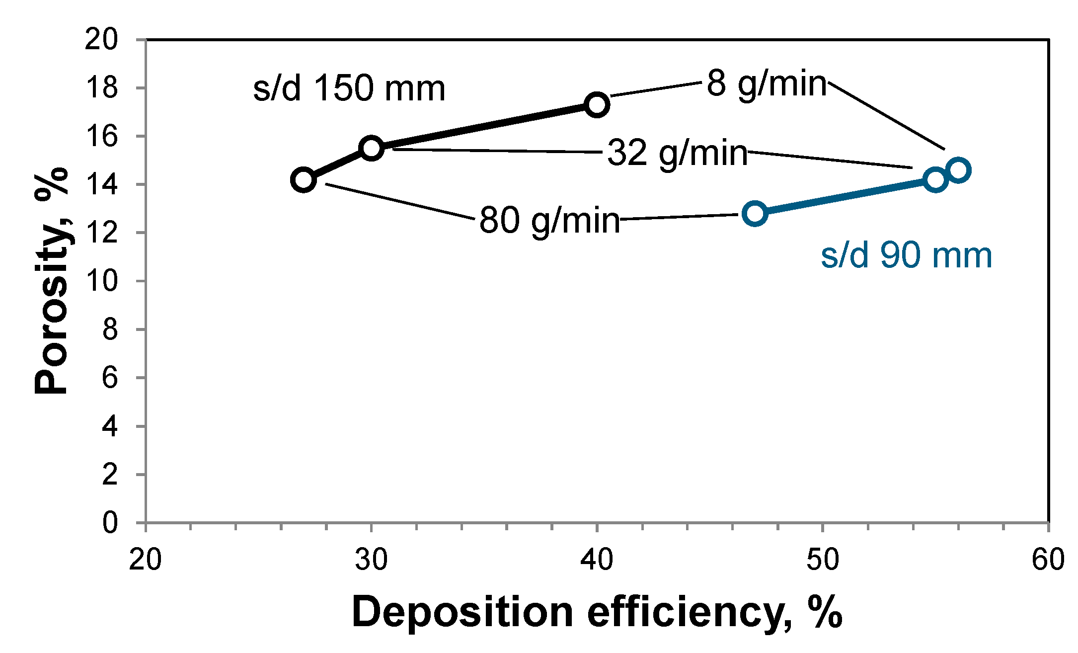
The results indicate that the processing of LZ by APS must be done at limited power in order to avoid inhomogeneous evaporation. Comparing the deposition efficiencies for the use of the different torches, power levels, and plasma gas compositions (
Table 3), the highest values were found at the higher input power levels (
Figure 3). However, the differences to the samples sprayed at low power are relatively small, such that only minor losses must be accepted for the sake of desired coating stoichiometry. Only the deposition efficiency for TriplexPro™-210 with argon–hydrogen parameter was poor (run 143, not plotted).
Furthermore, porosities were determined by digital image analyses. The images were binarized setting a user-defined greyscale threshold. Then, the areas related to the pores and voids were measured. The porosities reveal that the coatings sprayed at high power are too dense to be applied as TBCs. Thus, spraying at low power level helps also to increase porosities towards the requirements on TBCs. The low powder feed rate can explain the fact that similar deposition efficiencies were observed when using the TriplexPro™-210 and the F4. At higher rates, considerable differences should be expected. Hence, the use of the F4 torch was not continued.
Because the porosities at low power (22 kW) still appeared not to be entirely sufficient, the spray distance and the powder feed rate were increased (
Table 4).
Figure 4 gives the corresponding deposition efficiencies and the porosities determined by image analysis for the use of this torch with Ar–He plasma gas mixture and powder 321 M. While there are obvious effects of the spray distance and the feed rate on the deposition efficiency, the effect on the porosity is less pronounced.
With the TriplexPro™-210, different plasma gas mixtures were also tried to obtain colder conditions, and thus to increase the porosity. Using only 50 slpm Ar as well as 70 slpm Ar + 6 slpm He at 90 mm and 150 mm spray distance led to coarse non-molten deposits. Furthermore, the deposition efficiencies were poor, so these results are not presented here in detail; this direction was not followed up.
Based on the overall results obtained so far, the following spray parameters were selected for the first burner rig test samples: TriplexPro™-210 with Ar–He plasma gas mixture, 275 A (22 kW), powder feed rate 8 g/min, powder 321 M. Two samples sprayed at 90 mm distance survived only seven and three cycles, respectively, and another two samples sprayed at 150 mm reached only 14 and 16 cycles, respectively.
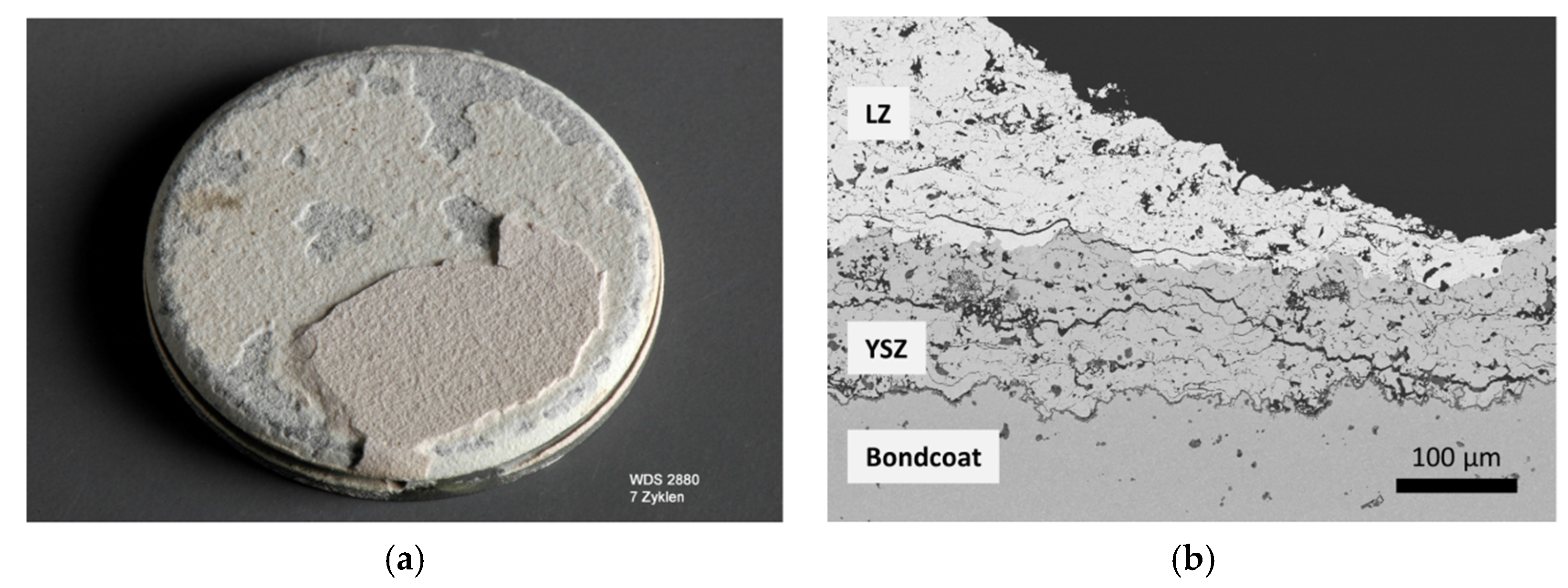
Figure 5 shows one cycled example. The coatings failed due to the early formation of cracks in the ceramic layers. Obviously, the compliance of the system is poor, qualified by the characteristics of the microstructure. It is obvious that the overall porosity is still too low. As the microstructure is obviously dominated by inter- and intra-splat cracks, the lack of finely-distributed pores of a more globular shape is supposed to be a further reason for the insufficient strain tolerance. In the following, the approach to improving this situation was to select different feedstock powders.
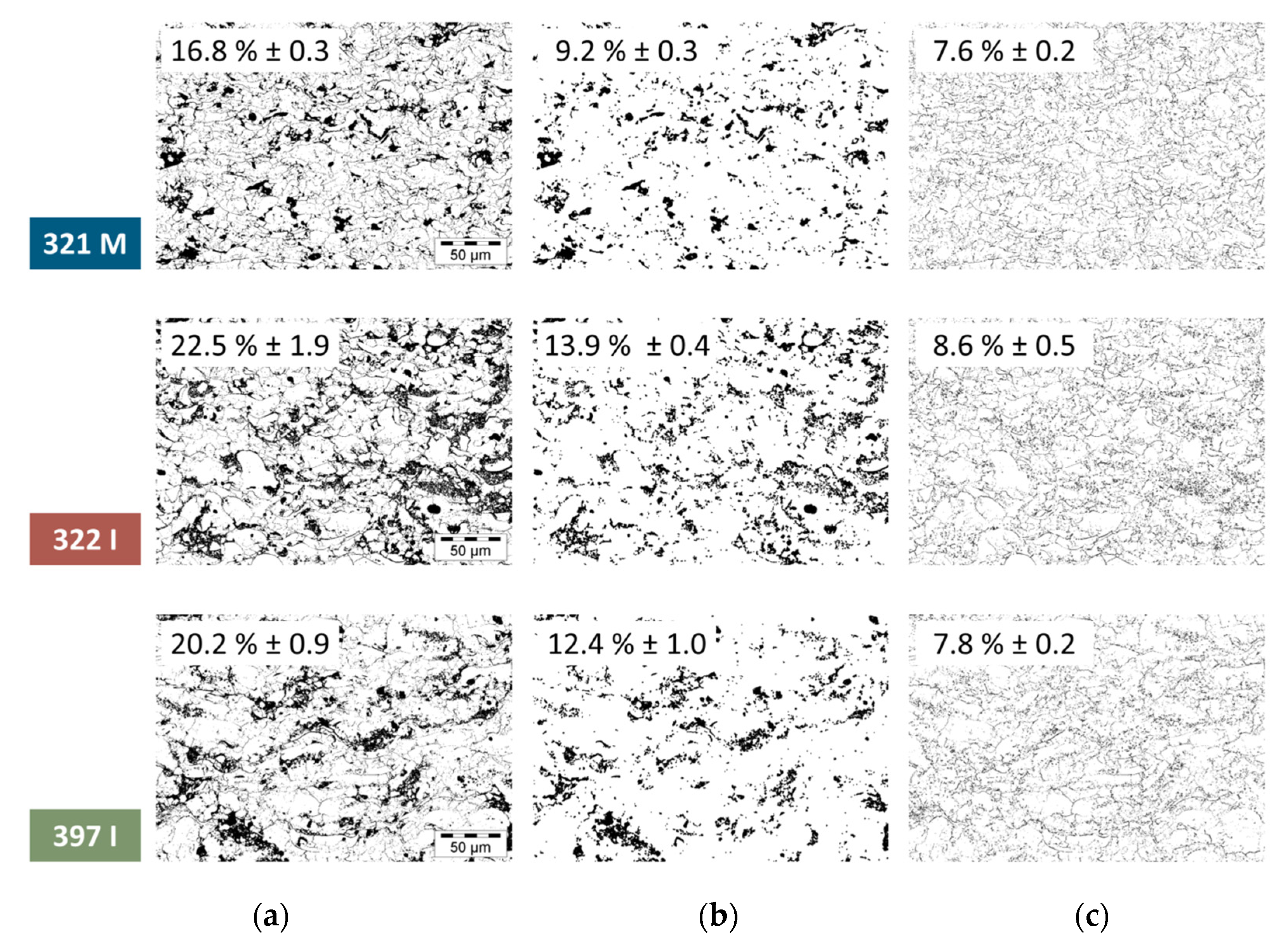
3.2. Powder Feedstock Selection
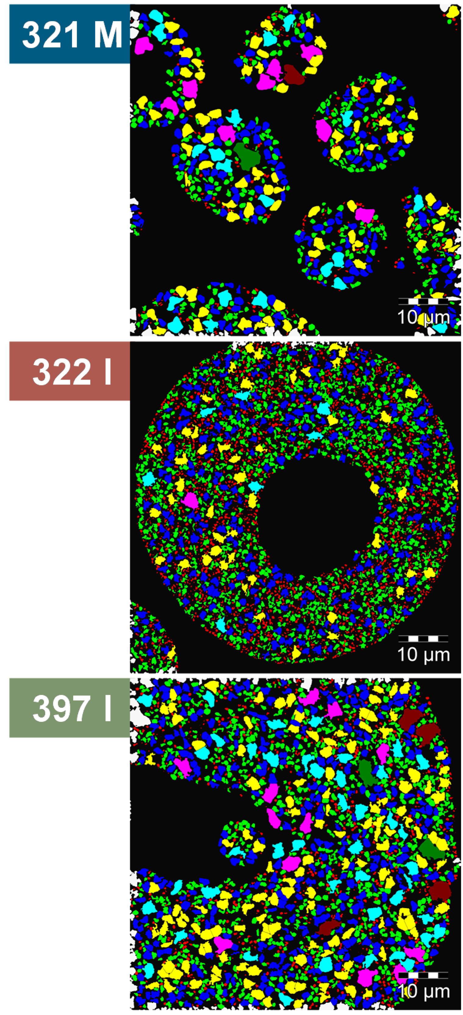
The alternative powders 322 I and 397 I had almost stoichiometric compositions comparable to the 321 M used so far. However, the particle size distribution was shifted considerably to larger diameters (see
Table 1). Furthermore, the internal microstructure of the particles was finer, as can be seen from typical cross-sections of powder particles in
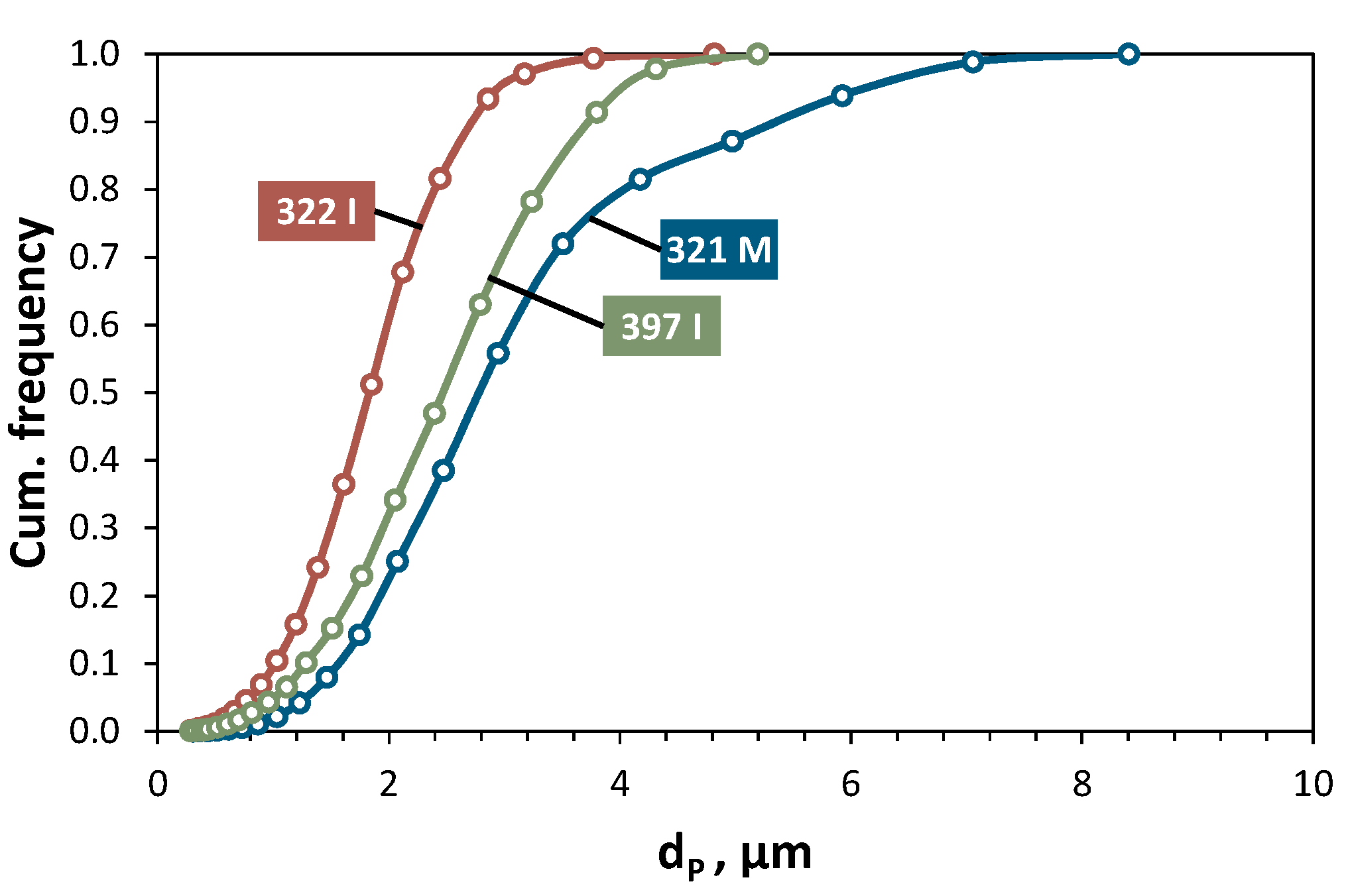
Figure 6. The diameters
dP of these primary particles (i.e., diameters of equivalent circles equal in area) were evaluated by digital image analyses. The corresponding volumetric distributions are given in
Figure 7, where each curve was averaged from three SEM images. It is evident that the 321 M powder contained significantly larger primary particles compared to 322 I and 397 I.
The large particle diameters and the small primary particle size have a significant effect on the coating microstructures.
Figure 8 gives three typical examples sprayed with the three investigated powders using the TriplexPro™-210 torch at low power (22 kW) and with the Ar–He plasma gas mixture. Besides the coarse more-or-less globular porosity fractions, the fine fractions appear differently. For the 321 M feedstock, it is mainly a network of long and narrow inter-splat and intra-splat cracks, while for the 322 I and the 397 I powder, the fine porosity also consists of many accumulations of globular pores. It is suggested that the melting grade of the 321 M feedstock was higher due to the smaller granule size, while in case of the 322 I and the 397 I powder, partly unmolten fractions were embedded in the coatings. In these domains, the fine primary particle structure was partially preserved.
The coarse porosity fraction was determined by the application of morphological dilatation and erosion filters, and then subtracted from the total porosity [
17] to obtain the fine fraction. The percentages were averaged from three SEM images for each feedstock. Considering the fine porosities, it should be kept in mind that the fractions are volumetric, so small differences imply large variances in the numbers of voids.
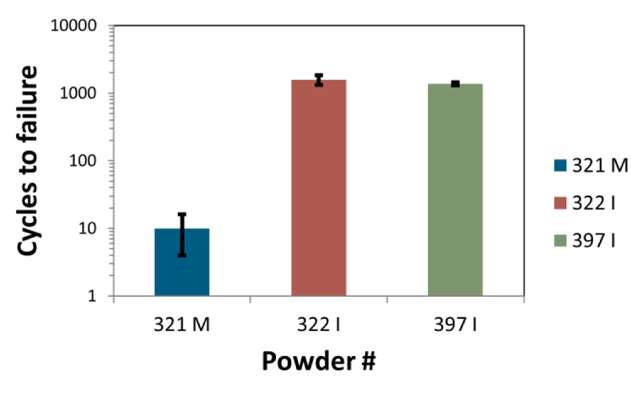
Using the 322 I and 397 I powders, two burner rig test samples were each sprayed with the same parameters. The corresponding as-sprayed microstructures can be seen by looking at the examples in
Figure 8. In
Figure 9, the cycles to failure are displayed; the results for the test samples from powder 321 M (mentioned above) are given as a reference. The lifetimes were 1398 and 1750 cycles for the 322 I powder and 1318 and 1423 cycles for 397 I, respectively. These results correspond to what was already reached some time ago [
8] using the older Triplex I torch with low power capability (21 kW). Furthermore, the results correlate with the porosity characteristics. With the 322 I feedstock exhibiting the largest powder grains and the smallest primary particles, the highest coarse and fine porosities were obtained. It is likely that the fine porosity content was still larger than resolved by the SEM images. The fine pore structures contained much more globular voids beside the crack network. The importance of this kind of fine porosity for the properties and lifetimes of TBCs was already reported for Gd
2Zr
2O
7/YSZ double-layer systems in [
18].
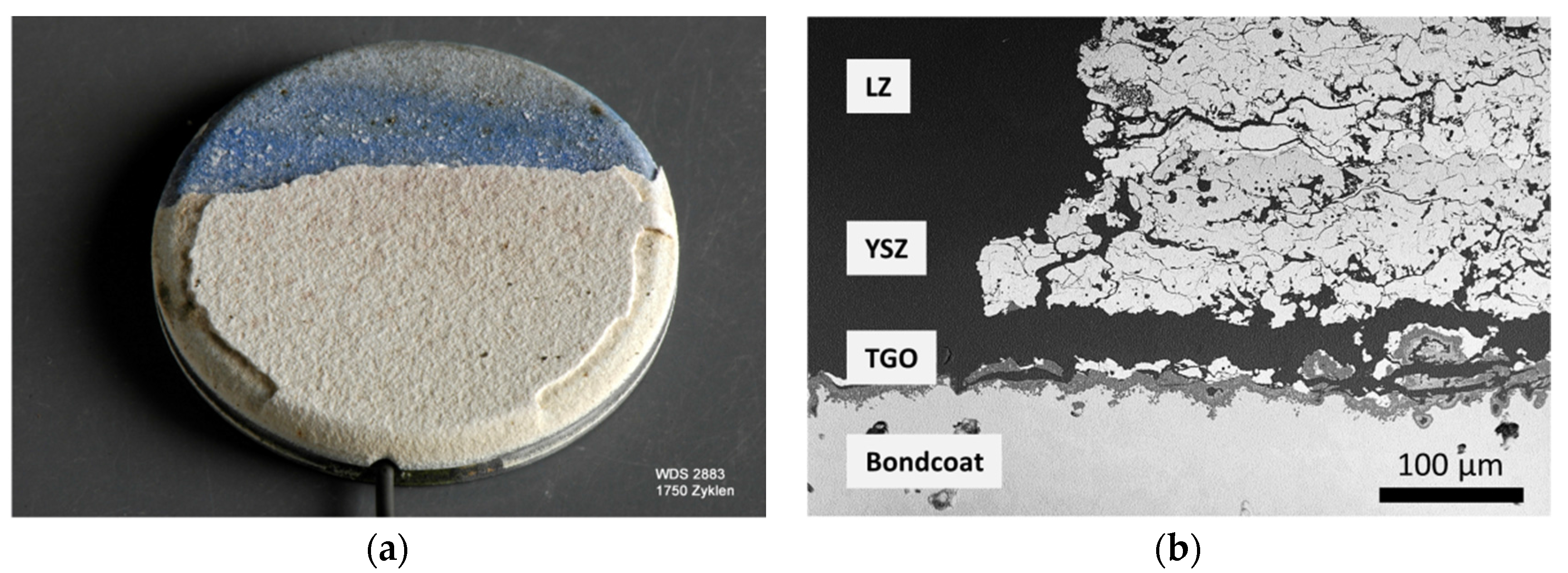
The failure of the samples was induced by the growth of the TGO at the interface of bondcoat and ceramic top coat (
Figure 10).The ceramic topcoat was obviously sufficiently strain tolerant to accommodate the thermal stresses due to the thermal mismatch with the metallic substrate and the temperature gradient in the burner rig.
It must be noted that these porous, compliant structures could be more prone to erosion-related damage. In such cases, dense vertically cracked coatings (DVCs) can offer improved resistance. However, since DVC deposition typically involves a higher degree of plasma enthalpy and heat flux, the preferential La depletion might again become an issue—this is still to be investigated.


