Article

The Microstructure and Wear Resistance of a Copper Matrix Composite Layer on Copper via Nitrogen-Shielded Arc Cladding

School of Mechanical Engineering, Qingdao University of Technology, Qingdao 266033, China
*
Author to whom correspondence should be addressed.
Coatings 2016, 6(4), 67; https://doi.org/10.3390/coatings6040067
Submission received: 1 November 2016 / Revised: 27 November 2016 / Accepted: 30 November 2016 / Published: 6 December 2016

Abstract

:
A TiN and TiN·Ti2Cu reinforced copper matrix composite layer was cladded onto a T3 copper substrate to improve the anti-wear performance of copper products by means of the nitrogen-shielded gas tungsten arc cladding method (N2-GTAC). Better than the traditional preparation method of TiN, the TiN particles in the cladding layer were in situ generated using N atoms of shielding gas and Ti atoms of pre-deposited metal powders. In addition, the composite phase TiN·Ti2Cu occurred in the cladding layer, which also had a positive effect on anti-wearing. As Ti increased, the amount and grain size of TiN·Ti2Cu and TiN increased as a result. The hardness of the cladding layer increased with the increasing amount of reinforced phase generated in the layer. The hardness of the layer reached a maximum of 410 HV, which is nearly 5.1 times greater than that of copper. The TiN·Ti2Cu- and TiN-reinforced phases improved the wear resistance of the cladding layers. The cladding layer with 15 wt % Ti had the longsest launch stage (600 s) and the lowest fiction coefficient (0.56).

1. Introduction

Copper and its alloys are widely used in the manufacturing industry for rotors and stators of power generators, thermal exchanging parts, electric conducting parts in mechanical equipment, and so on. They have excellent thermal and electrical conductivity, plasticity, and corrosion resistance. However, the major failure of copper is its surface wear, which induces the surface’s deformation, lowering the strength and hardness of copper materials compared to other materials. Therefore, there has been a great demand for improving the performance of its surface [1,2,3,4]. Among the various surface modification methods, one method—the in situ generation of particle-reinforced composites on the surface of metal materials—has the advantage of high controllability and cost-effectiveness, making it an effective way to enhance the surface wear resistance and service life of equipment [5]. Nowadays, there are several methods of in situ generation on metal surfaces, including arc cladding [6,7], laser cladding [8,9,10,11], electron beam cladding [12,13], and plasma arc cladding [14,15]. Among these methods, arc cladding is becoming one of most promising methods as it is easy to facilitate, highly flexible, and cost-effective.
TiN particles are one of most common reinforced particles that are used to enhance the surface property of metals, as it has a high melting point and hardness, perfect ductility, wear resistance, and electric conductivity [16,17,18]. Some researchers have used laser cladding to prepare a TiN/Ti3Al particle-reinforced composite on a titanium alloy surface [19,20]; some researchers have used arc cladding and powder made of Ti, BN, and Ni to prepare a TiN-reinforced nickel matrix composite on the surface of 16Mn steel [21]; other researchers have used the power metallurgy method to prepare a nanoscale Cu-based composite with TiN particles [22] In addition, Ti2Cu particles regarded as an inevitable reaction of copper and titanium are a hard and brittle phase and usually used as reinforced particles in copper matrix materials. However, TiN·Ti2Cu-TiN-reinforced copper matrix composites prepared in situ on the surface of a copper device using arc cladding has seldom been reported.
In this paper, a TiN- and TiN·Ti2Cu-reinforced copper matrix composite layer was generated via a N2-shielded gas tungsten arc cladding method. The in situ transaction pre-deposited between the nitrogen as a shielding gas, and the Ti and Cu from the powder was conducted on the surface of T3 copper aiming to form TiN·Ti2Cu and TiN particles. The analysis is focused on the microstructure and wear resistance of the TiN- and TiN·Ti2Cu-reinforced copper matrix composite.

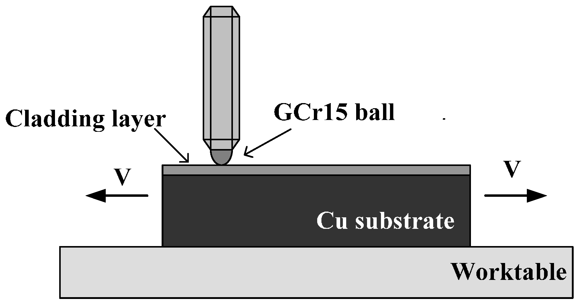
2. Materials and Methods

The materials used in this study include commercial pure copper plates (T3, Cu ≥ 99.7 wt %) with dimensions of 100 mm × 100 mm × 10 mm, and the plates were ground with water proof abrasive papers up to 500 grit and cleaned with acetone. The titanium and copper powders were selected and mixed up as cladding materials, for which the proportion of Ti was set as 5 wt %, 10 wt %, 15 wt %, and 20 wt %. The titanium powder had an average particle size of 75 μm, and the purity was greater than 99.95%; the copper powder had an average particle size of 100 μm, and the purity was over 99.5%. The copper and titanium powders were mixed according to certain proportions with turpentine oil and were then pre-coated on the surface of T3 copper with a 1.5 mm thickness. The N2-shielded gas tungsten arc was used as a heating resource to clad, and the cladding parameters were as follows: current: 200 A; cladding speed: 5 mm/s; shielded gas flowing velocity: 10 L/min. A thorium tungsten electrode was selected as a negative electrode, the diameter of which was 2.0 mm.
The cross sections of the cladding specimens were prepared for metallographic analysis via a standard polishing technique. The microstructures of the cladding specimens were examined via light microscopy (PMG3) (Olympus, Tokyo, Japan), and scanning electron microscopy (SEM, S-570) (Hitachi, Tokyo, Japan) equipped with an energy dispersive X-ray spectrometer (EDS, TN5500). Phase identification was carried out with an X-ray diffractometer (XRD, D8 Advance) (Bruker, Peoria, IL, USA). The harnesses along the depth of the transverse section were measured using a micro-Vickers hardness test with a load of 100 g and a loading time of 5 s. The friction coefficients were tested via multi-function friction and a wear tester (UMT-3). The specimens were cut in dimensions of 20 mm × 10 mm × 10 mm, and a sliding ball (GCr15 steel, HRC 60) with a diameter of 4 mm was used as the counter body, shown in Figure 1. The wear tests were performed at room temperature at a reciprocating sliding speed of 10 mm/s and a stroke of 5 mm, at a constant normal load of 5 N and under dry sliding conditions. Each test was conducted for 30 min, and the surface of the wear specimens were observed via SEM.

3. Results and Discussion

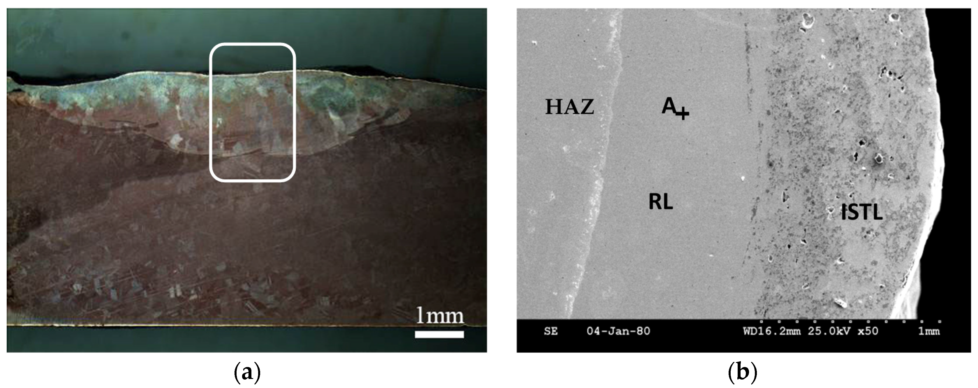
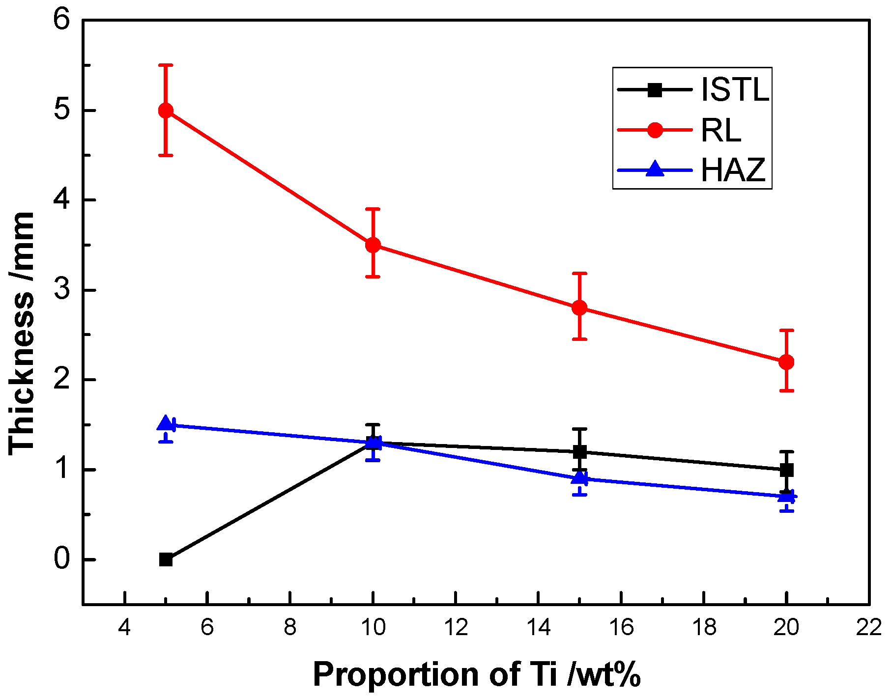
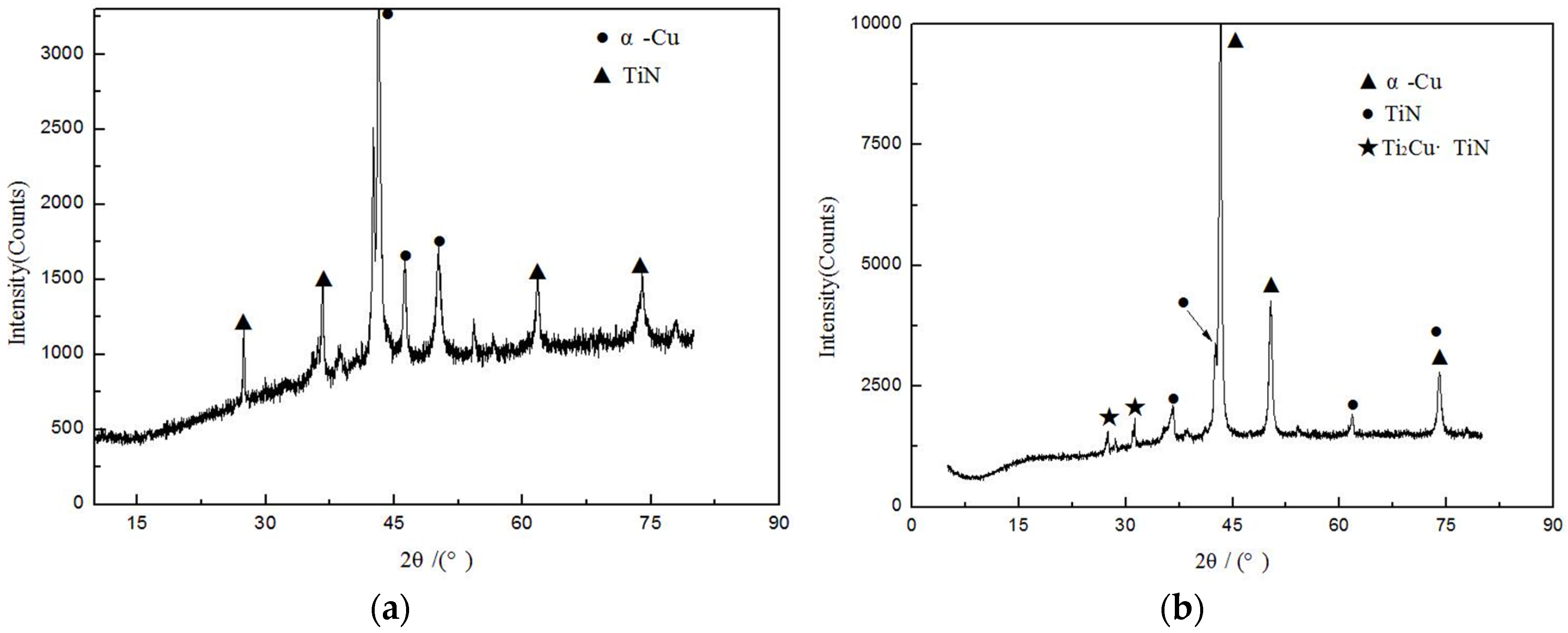
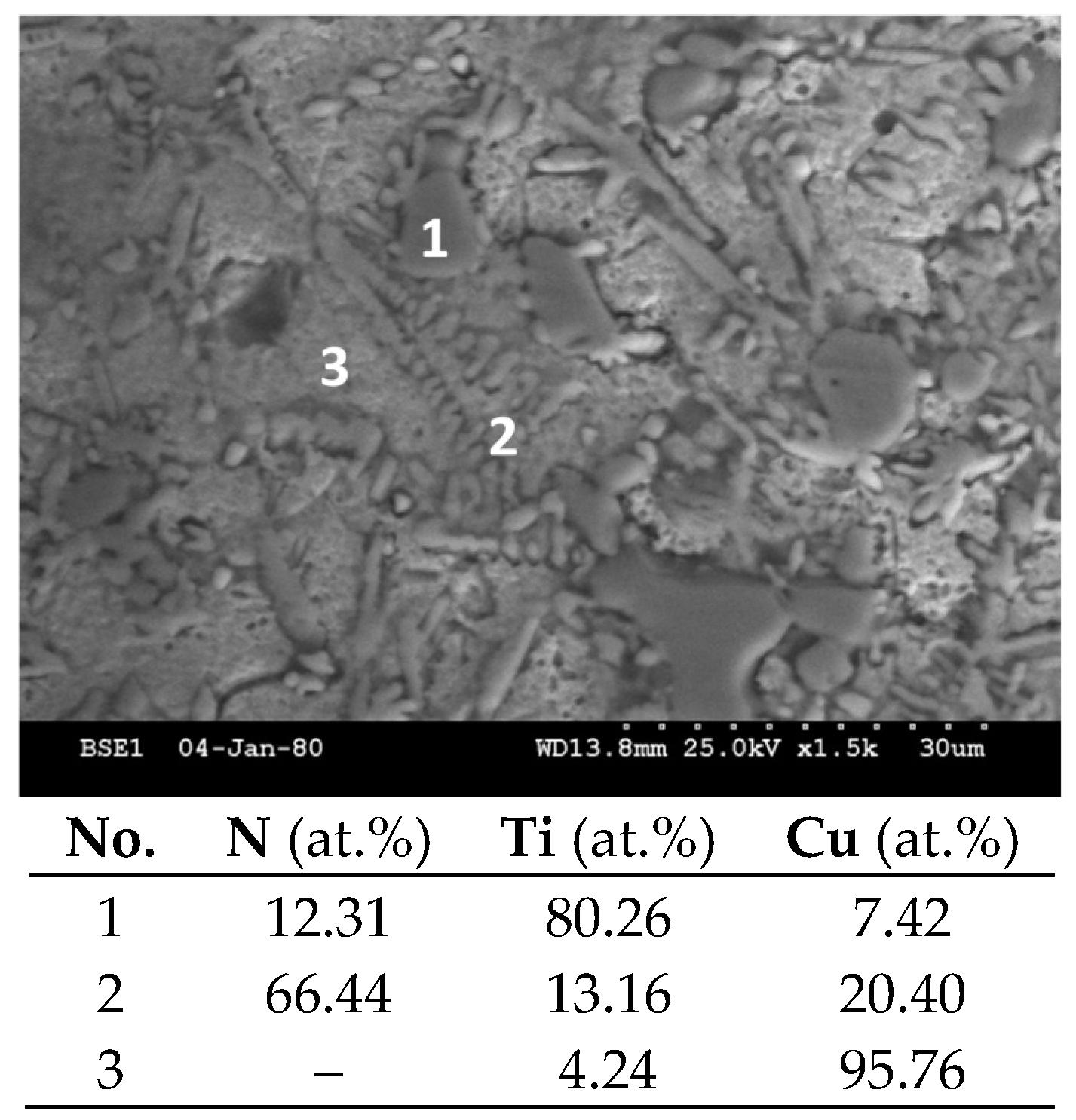
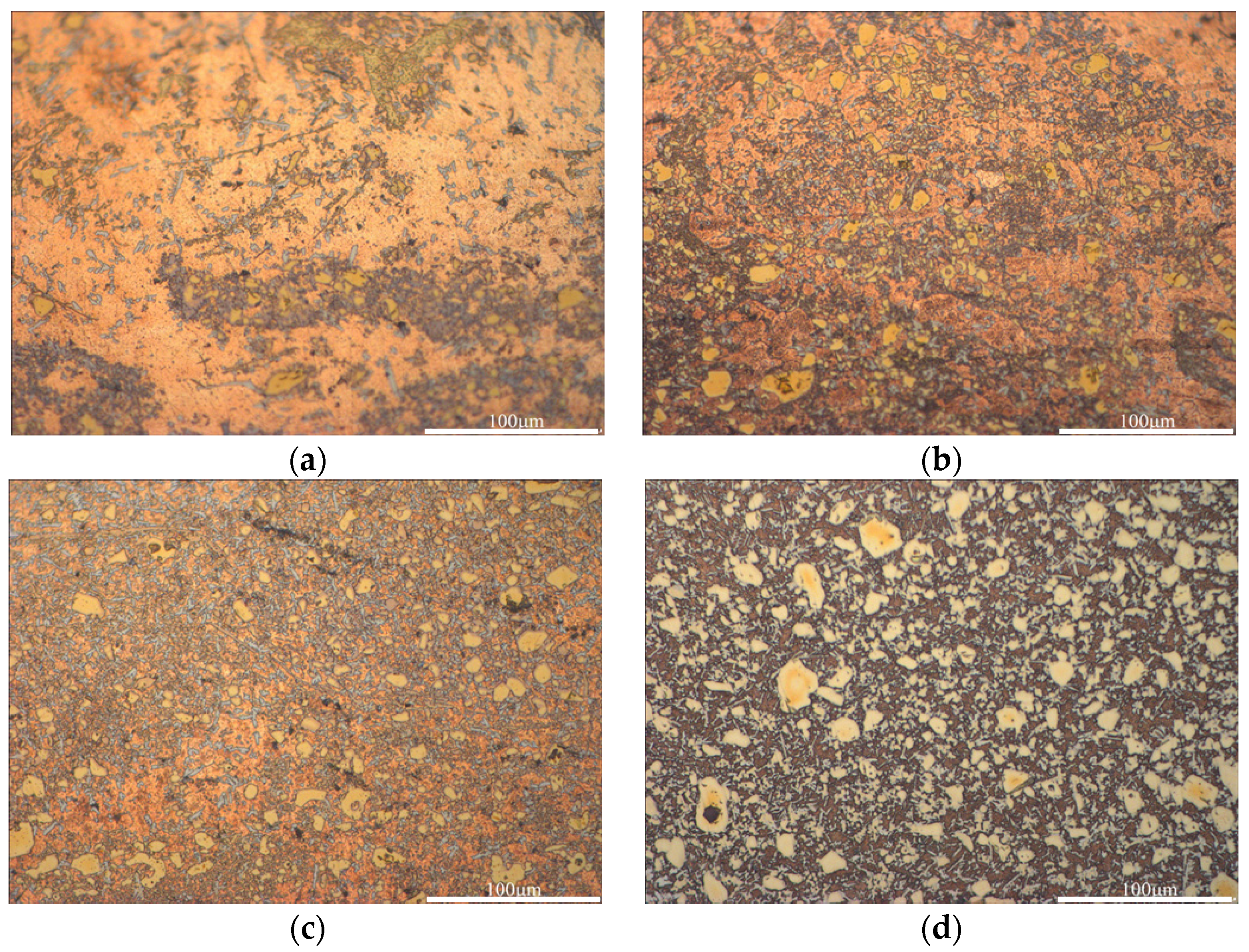
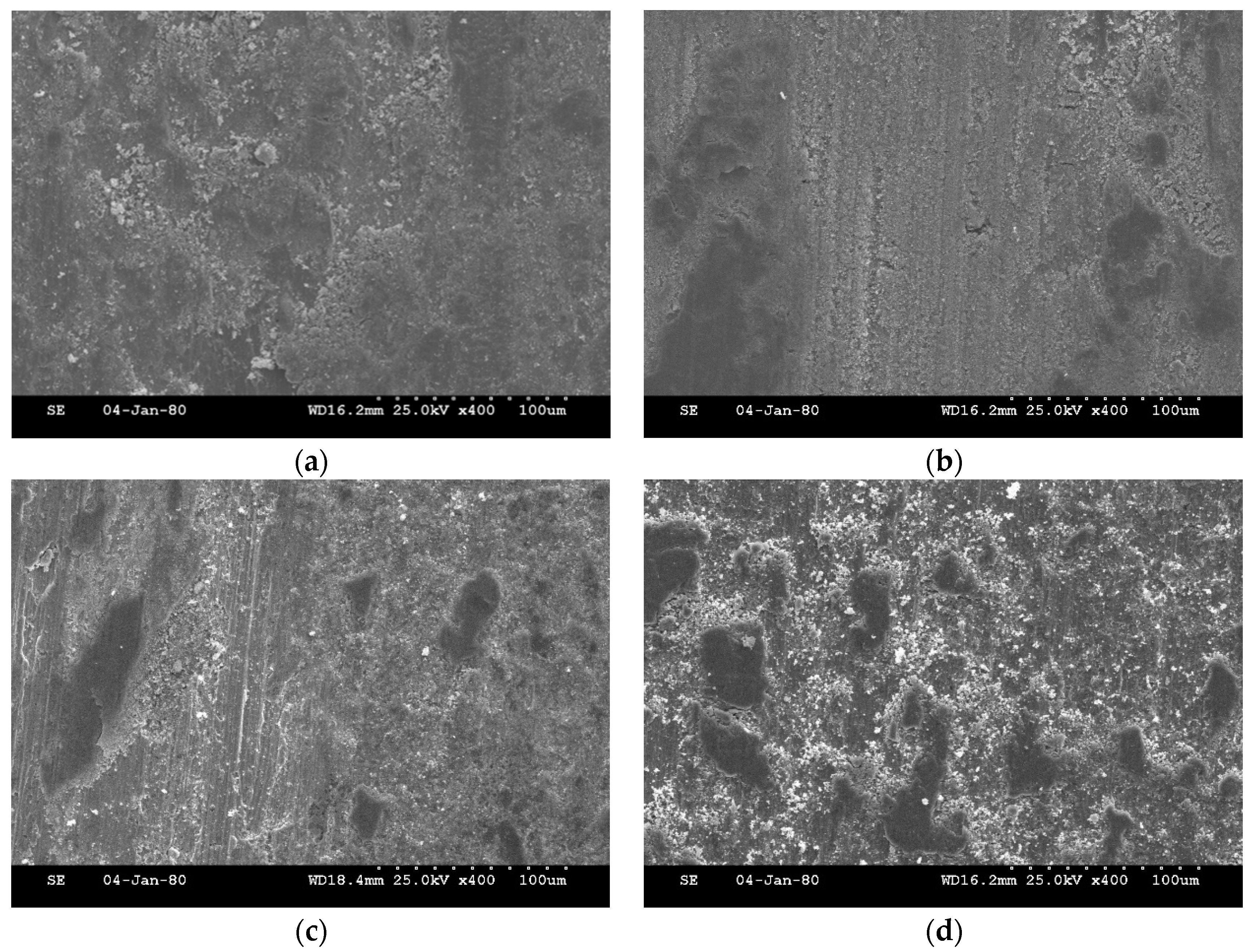
3.1. Morphology and Microstructure of the Cladding Layer

Figure 2a shows the macro profile of the cross section of 15 wt % cladding specimens; good metallurgy bonding occurred between the base metal and cladding alloy powders, and there were no cracks or pores in the reaction interface. It is evident from Figure 2b that the cladding layer could be divided into two layers—the in situ transaction layer (ISTL) on the top and the remelting layer (RL) in the middle. Moreover, there is a heat affected zone (HAZ) between the RL and base metal. The in situ transaction mainly emerged at the domain of the ISTL, as the density of Ti powder was lower than that of the Cu, and melting Ti powder remained in the top region reacting with N to form a second particle. Thus, in the ISTL region, some second phase particles were distributed among the matrix as an effect of in situ transaction. In addition, in the RL region, the columnar crystals were in a large majority. Via EDS analysis of the RL, Point A contains 97.82 wt % Cu and 2.18 wt % Ti, and is identified as α-Cu (Ti). During the formation of this RL, with the heating effect of the arc cladding, some base metals melted while failing to mix with the cladding powder, and then solidified into columnar crystals (α-Cu).
The thickness of the ISTL, the RL, and the HAZ with the Ti powder varied from 5 wt % to 20 wt % (Figure 3). When Ti content was limited to 5 wt %, the ISTL was not observed at the surface of the cladding layer, and the thickness of the RL was about 5 mm, the maximum thickness among these specimens. The main reason for this may be that, in this content range, the formation of in situ phases is too limited to form an independent area and that these phases are mainly located in the RL, which may be relevant to the maximum thickness of the RL. When Ti content was up to 10 wt %, an ISTL formed on the top of the cladding layer, which was about 1.3 mm in thickness. As Ti content increased, the thickness of the independent ISTL showed a declining trend, the thickness of the RL dropped significantly from 5 mm to 2.2 mm, and the thickness of the HAZ decreased slightly from 1.5 mm to 0.7. There are two reasons to explain this variation: first, an increasing amount of Ti in the powder led to a decrease in the thermal conductivity of the mixed powder, as the thermal conductivity coefficient of titanium is less than one-tenth of copper; second, the reaction of TiN and the intermetallic compounds (IMCs) needed to absorb the heat from the heat source. Therefore, the more Ti content the powder had, the more heat was assumed in the in situ transaction; with the same amount of heat input, the thicknesses of the ISTL, the RL, and the HAZ each showed declining tendencies.
The XRD analysis of the cladding layer with 5 wt % and 20 wt % Ti is shown in Figure 4. It is clear that, after arc cladding, the diffraction peaks of β-Ti disappeared, and the diffraction peaks of the TiN phase alternatively appeared. Moreover, the diffraction peak of the α-Cu phase remained. According to the chemical composition of the powder and base metal, it is easy to conclude that TiN was in situ generated in the cladding layer using the Ti atoms from the metal powder and the N atoms from the shielding gas. Two phases, i.e., α-Cu and TiN, formed in the layer of the 5 wt % specimen, while three phases, i.e., α-Cu, TiN, and Ti2Cu·TiN, formed in the layer of the 20 wt % specimen. It is worth mentioning that TiN was not only in the single phase, but also in the form of a composite phase—Ti2Cu·TiN. Obviously, the Ti2Cu phase was synthesized in the arc molten pool using Ti and Cu atoms to form IMCs, and Ti2Cu combined with TiN generated a composite phase—Ti2Cu·TiN.
Figure 5 shows the microstructure of the cladding layer of the 20 wt % specimen, and it can be seen that there are three different shape structures in this profile. Thus, these points represent these three structures and were measured by EDS analysis. Point 1 shows that there is a large amount of Ti and small proportions of N and Cu in the area around that point. Combined with the result of XRD, the phase around Point 1 can be defined as Ti2Cu·TiN. The phase in the region of Point 2 has a dendrite crystal structure that has a large proportion of N and small proportions of Ti and Cu. It can be inferred that N reacted with Ti to form TiN and residual N solutes in α-Cu. Therefore, the phase in the region of Point 2 can be defined as TiN and the α-Cu that solutes some N. In addition, in the Point 3 area, the main element is Cu, which means that the phase in this area is Ti, an α-Cu dissolving element.
The microstructures of the cladding layer with variation in Ti content are shown in Figure 6. It can be seen that the black and yellow phase is Ti2Cu·TiN, the fine silver-gray phase is TiN, and the matrix phase is α-Cu. In the specimen of 5 wt % Ti, the main phase is α-Cu with some silver-gray TiN phase distributed therein. In the specimen of 15 wt % Ti, the amount of yellow phase Ti2Cu·TiN, which is dispersed uniformly, markedly increases, as TiN does. The average size of the Ti2Cu·TiN phases is 10 μm. In the specimen of 20 wt % Ti, a large amount of Ti2Cu·TiN emerges and becomes the main phase in the cladding layer, and the average size of Ti2Cu·TiN increases to 15 μm. Through a comparison of specimens of different Ti proportions, it could be concluded that, as Ti increased in the cladding powder, the amount of Ti2Cu·TiN phase, as well as its shape, increases. By contrast, the increasing trend of TiN is limited. The proportion of these three phases varying in Ti content has a vital influence on the mechanical property of the cladding layer.

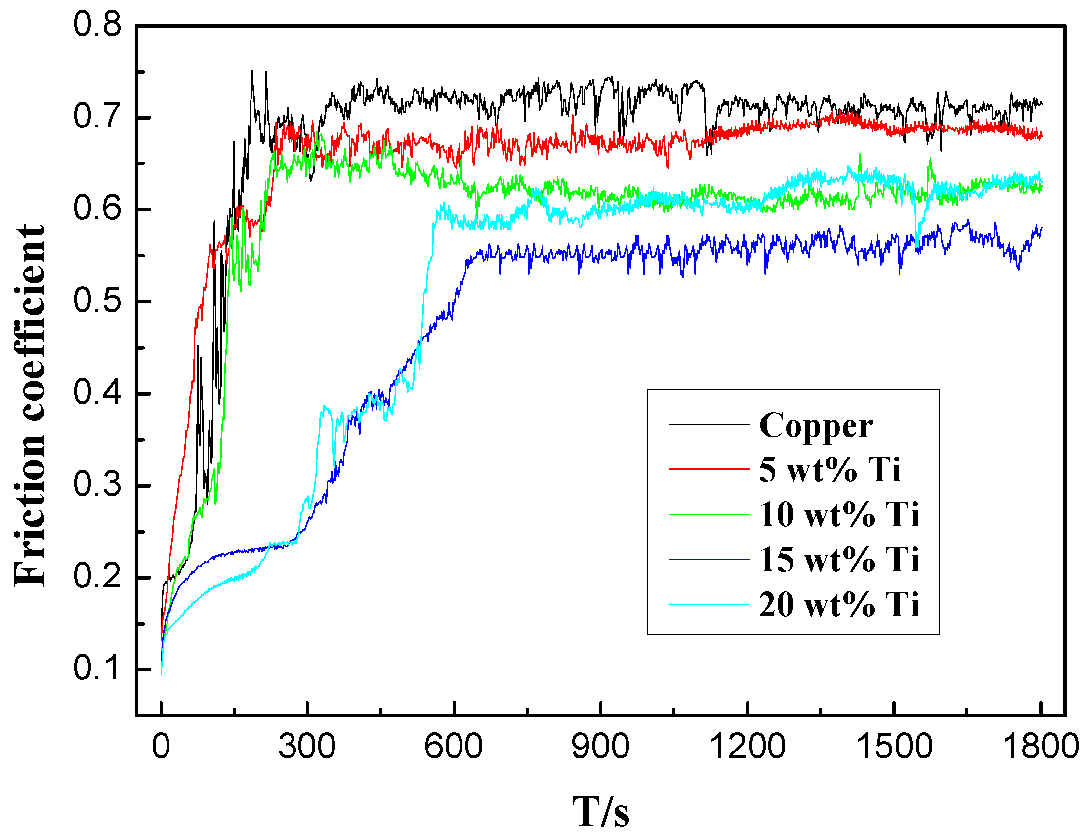
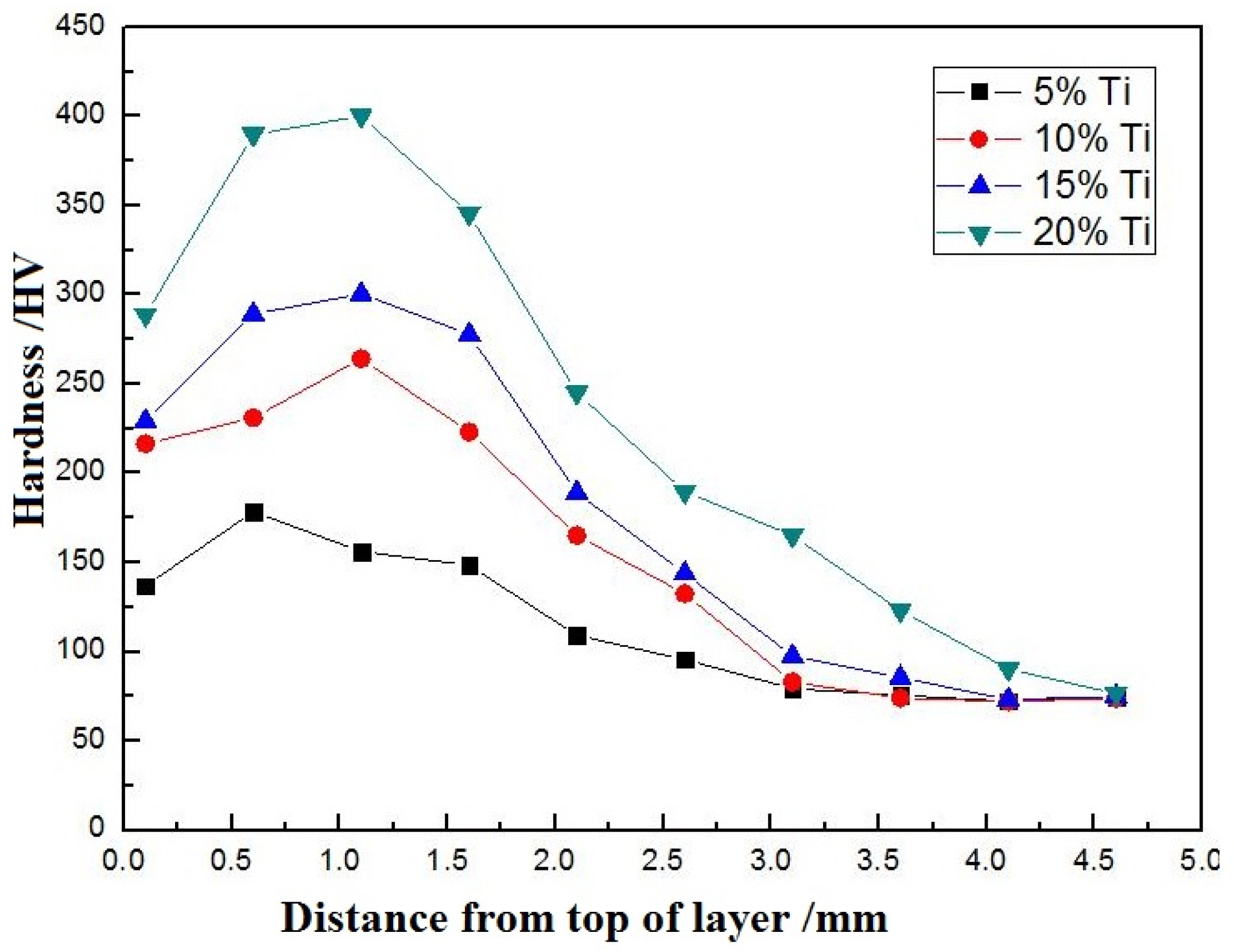
3.2. Micro-Hardness and Anti-Wear Performance of Cladding Layer

Figure 7 shows the hardness of cladding layers with variation in Ti content. It can be seen that the hardness varies in layers with different Ti amounts. Taking the 20 wt % Ti specimen, for example, the maximum occurs in the region of the ISRL, which is about 410 HV. This hardness is 5.2 times greater than that of the T3 copper (81 HV). The maximum hardness of 15 wt %, 10 wt %, and 5 wt % is 305 HV, 271 HV, and 178 HV, respectively. The significant improvement in the hardness of the cladding layer is mainly due to the fact that the Ti2Cu·TiN and TiN phases played a role in the second phase, strengthening the matrix. In addition, within the sample with the same Ti amount, the variation curve of the hardness increases first and decreases afterwards because the reinforced phases at the surface were burned and significantly lost. Usually, the hardness 0.5–1 mm away from the surface reaches the climax point.
Figure 8 shows the friction coefficients of different amounts of Ti and the substrate, and it is evident that, with the addition of the cladding layer on the copper, the friction performance improved relative to the T3 copper. The launch stage was about 150 s, and the friction coefficient was 0.72. By contrast, with the cladding layers distributed with TiN and Ti2Cu·TiN, the launch stages last longer: 210 s (5 wt % Ti), 208 s (10 wt % Ti), 638 s (15 wt % Ti), and 552 s (20 wt % Ti). The increase in the duration of the launch stage entails that the cladding layer is more wear-resistant than the substrate. Upon reaching the stable friction period, the friction coefficients of the layer with different Ti amounts tended to stabilize. Their values are as follows: 0.68 (5 wt % Ti), 0.61 (10 wt % Ti), 0.56 (15 wt % Ti), and 0.62 (20 wt % Ti). This reveals that, although the friction coefficient of 5 wt % is close to the substrate, the friction coefficients improved when the proportion of Ti was above 10 wt %. Among the specimens with different Ti amounts, the cladding layer of 15 wt % Ti had the lowest friction coefficient 0.56.
Figure 9 shows the wearing morphology of the substrate and layers with different Ti amounts. Ploughed grooves and copper abrasive chips on the T3 copper are evident (Figure 9a). The grooves were generated as a cutting function of the GCr15 ball, with a certain level of sliding tangential force on the T3 surface. The main reason for the abrasive chips is that the T3 copper surface experienced a serious softening effect and plastic deformation during the abrasion with the GCr15 ball. Abrasive chips, which adhered to the adjacent area of the surface, then formed. Therefore, the main abrasive mechanisms of the T3 copper were micro-cutting and adhesive wear. From Figure 9b, it is evident that the main abrasive mechanism was micro-cutting, as there are uniform grooves on the surface of the cladding layer. The adhesive wear effect here is not obvious, because the layer was reinforced by Ti, and the hardness improved. Figure 9c shows that the surface of the wearing area was relatively flat, and the grooves appear narrow and short, which is mainly because the occurrence of Ti2Cu·TiN and TiN reinforced the matrix and kept the GCr15 ball from pressing into the cladding layer. Figure 9d shows the wearing appearance of the 20 wt % specimen; the wearing area was rougher than the other specimens, and there are large-sized pits exposed to the air. This coarse wearing surface resulted in an increase in friction coefficient.

4. Conclusions

  • The TiN·Ti2Cu- and TiN-reinforced copper matrix composite layer was in situ prepared on the surface of T3 copper successfully by means of N2 shielding gas tungsten arc cladding technology. The interface between the cladding layer and the substrate has a fine and uniform distribution without cracks and slags. As Ti increased, TiN·Ti2Cu and TiN increased as a result.
  • The hardness of the cladding layer increased as the amount of reinforced phase generated in the layer increased. The hardness of the layer reached a maximum of 410 HV, 5.1 times greater than that of copper.
  • The TiN·Ti2Cu- and TiN-reinforced phases improved the wear resistance of the cladding layers. The cladding layer with 15 wt % Ti had a longest launch stage of 638 s and a minimum fiction coefficient of 0.56.

Acknowledgments

This work was supported by the Natural Science Foundation of China (Grant No.51205218), the China’s Post-doctoral Science Fund (Grant No. 2013M531562), and Qingdao applied basic research projects (14-2-4-84-jch).

Author Contributions

Yinan Li and Lei Zhang conceived and designed the experiments; Xianbao Liu and Zhikang Zhou performed the experiments; Yinan Li and Zilong Peng analyzed the data; Lei Zhang contributed reagents/materials/analysis tools; Yinan Li wrote the paper.

Conflicts of Interest

The authors declare no conflict of interest.

References

  1. Wang, Y.Y.; Liang, Z.P.; Zhang, J.W. Microstructure and antiwear property of laser cladding Ni-Co duplex coating on copper. Material 2016, 9, 634–643. [Google Scholar] [CrossRef]
  2. Zhang, Y.Z.; Tu, Y.; Xi, M.Z.; Shi, L.K. Characterization on laser clad nickel based alloy coating on pure copper. Surf. Coat. Technol. 2008, 202, 5924–5928. [Google Scholar] [CrossRef]
  3. Yan, H.; Zhang, P.L.; Yu, Z.S.; Lu, Q.H.; Yang, S.L.; Li, C.G. Microstructure and tribological properties oflaser-clad Ni-Cr/TiB2 composite coatings on copper with the addition of CaF2. Surf. Coat. Technol. 2012, 206, 4046–4053. [Google Scholar] [CrossRef]
  4. Dehm, G.; Bamberger, M. Laser cladding of Co-based hardfacing on Cu substrate. J. Mater. Sci. 2002, 37, 5345–5353. [Google Scholar] [CrossRef]
  5. Zhao, G.L.; Zou, Y.; Zou, Z.D. Research on in situ synthesised (Ti,V)C/Fe composite coating by laser cladding. Mater. Sci. Technol. 2015, 31, 1329–1334. [Google Scholar] [CrossRef]
  6. Meng, J.S.; Shi, X.P. Microstructure and properties of TiCp/Al composite coating by argon arc cladding. Trans. China Weld. Inst. 2011, 32, 73–76. [Google Scholar]
  7. Guo, G.L.; Yang, L. The investigation on wear resistance of Fe-based alloy coating by argon arc cladding. Appl. Mech. Mater. 2012, 217, 1247–1250. [Google Scholar] [CrossRef]
  8. Zhang, P.R.; Liu, Z.Q. Effect of sequential turning and burnishing on the surface integrity of Cr-Ni-based stainless steel formed by laser cladding process. Surf. Coat. Technol. 2015, 276, 327–335. [Google Scholar] [CrossRef]
  9. Liu, Y.H.; Qu, W.C. TiC reinforcement composite coating produced using graphite of cast iron by laser cladding. Materials 2016, 9, 815–825. [Google Scholar] [CrossRef]
  10. Candel, J.J.; Jimenez, J.A. Effect of laser irradiation on failure mechanism of TiCp reinforced titanium composite coating produced by laser cladding. J. Mater. Process. Technol. 2014, 214, 2325–2332. [Google Scholar] [CrossRef]
  11. Durakov, G.S.; Scheider, A. Effect of substrate temperature on microstructure and properties of the CuCr25 alloys produced by electron beam cladding. In Proceedings of International Symposium on Discharges and Electrical Insulation in Vacuum, Mumbai, India, 28 September–3 October 2014.
  12. Angelastro, A.; Campanelli, S.L.; Casalino, G.; Ludovico, A.D. Optimization of Ni-based WC/Co/Cr composite coatings produced by multilayer laser cladding. Adv. Mater. Sci. Eng. 2013, 1, 332–335. [Google Scholar] [CrossRef]
  13. Bataev, I.A.; Mul, D.O. Structure and tribological properties of steel after non-vacuum electron beam cladding of Ti, Mo and graphite powders. Mater. Charact. 2016, 112, 60–67. [Google Scholar] [CrossRef]
  14. Li, D.K.; Li, M.X. Effect of CeO2 on microstructure and properties of Fe-based coating produced by plasma arc cladding process. Trans. China Weld. Inst. 2011, 32, 109–112. [Google Scholar]
  15. Xia, D.; Xu, B.S. Experimental study on NiCrBSi multilayer coating cladded by micro—Plasma arc cladding process. Mater. Sci. Technol. 2009, 17, 645–648. [Google Scholar]
  16. Weng, F.; Yu, H.J.; Chen, C.Z. Microstructure and property of composite coatings on titanium alloy deposited by laser cladding with Co42+TiN mixed powders. J. Alloys Compd. 2016, 686, 74–81. [Google Scholar] [CrossRef]
  17. Alat, E.; Motta, A.; Comstock, R.J. Multilayer (TiN, TiAlN) ceramic coating for nuclear fuel cladding. J. Nuclear Mater. 2016, 478, 236–244. [Google Scholar] [CrossRef]
  18. Qi, Y.; Cao, Z.; Sheng, L.; Cao, R. Microstructure of Fe-based alloy composite coatings reinforced by Ti (C0.3N0.7) particles Tthrough laser cladding technology. J. Iron Steel Res. Int. 2013, 20, 78–82. [Google Scholar] [CrossRef]
  19. Liu, H.X.; Zhang, X.W. Microstructure and high temperature oxidation resistance of in-situ synthesized TiN/Ti3Al intermetallic composite coating on Ti6Al4V alloys by cladding process. J. Alloy. Compd. 2016, 670, 268–274. [Google Scholar] [CrossRef]
  20. Guo, B.G.; Zhou, J.S.; Zhang, S.T. Microstructure and tribological properties of in situ synthesized TiN/Ti3Al intermetallic matrix composite coatings on titanium by laser cladding and laser nitriding. Mater. Sci. Eng. A 2008, 480, 404–410. [Google Scholar] [CrossRef]
  21. Meng, J.S.; Ji, Z.S. Microstructure and technology research of In-situ synthesis TiN-TiB/Ni composite coating by arc cladding. Phys. Procedia 2013, 50, 253–260. [Google Scholar] [CrossRef]
  22. Mateusz, W.; Joanna, K.B. Copper metal matrix composites reinforced by titanium nitride particles. Key Eng. Mater. 2016, 682, 270–275. [Google Scholar]
Figure 1. Sketch of dry sliding friction and wear test.
Coatings 06 00067 g001
Figure 2. Cross-sectional view of macroscopic morphologies (a) and cladding layer (b) of 15 wt % Ti.
Coatings 06 00067 g002
Figure 3. The thickness of the ISTL, the RL, and the HAZ with varying Ti content.
Coatings 06 00067 g003
Figure 4. XRD analysis of the ISTL of 5 wt % Ti (a) and 20 wt % Ti (b).
Coatings 06 00067 g004
Figure 5. Microstructure morphology of the cladding metal in 20 wt % Ti powder and EDS analysis of point 1, point 2 and point 3.
Coatings 06 00067 g005
Figure 6. Cross-sectional microscopic images of the cladding metal layer (500×). (a) 5 wt % Ti; (b) 10 wt % Ti; (c) 15 wt % Ti; (d) 20 wt % Ti.
Coatings 06 00067 g006
Figure 7. The micro-hardness of the cladding layer with different Ti amounts.
Coatings 06 00067 g007
Figure 8. Friction coefficient of the cladding layer with different Ti amounts.
Coatings 06 00067 g008
Figure 9. Wear morphology of cladding layer with different Ti content: (a) T3 copper; (b) 5 wt % Ti; (c) 15 wt % Ti; (d) 20 wt % Ti.
Coatings 06 00067 g009

