Article

Study on the Growth of Holes in Cold Spraying via Numerical Simulation and Experimental Methods

1
Science and Technology on Marine Corrosion and Protection Laboratory, Luoyang Ship Material Research Institute, Qingdao 266101, China
2
Sunrui Marine Environment Engineering Co., Ltd., Qingdao 266101, China
*
Author to whom correspondence should be addressed.
Coatings 2017, 7(1), 2; https://doi.org/10.3390/coatings7010002
Submission received: 20 September 2016 / Revised: 28 November 2016 / Accepted: 7 December 2016 / Published: 30 December 2016
(This article belongs to the Special Issue Thermal Spray Technology)

Abstract

:
Cold spraying is a promising method for rapid prototyping due to its high deposition efficiency and high-quality bonding characteristic. However, many researchers have noticed that holes cannot be replenished and will grow larger and larger once formed, which will significantly decrease the deposition efficiency. No work has yet been done on this problem. In this paper, a computational simulation method was used to investigate the origins of these holes and the reasons for their growth. A thick copper coating was deposited around the pre-drilled, micro-size holes using a cold spraying method on copper substrate to verify the simulation results. The results indicate that the deposition efficiency inside the hole decreases as the hole become deeper and narrower. The repellant force between the particles perpendicular to the impaction direction will lead to porosity if the particles are too close. There is a much lower flattening ratio for successive particles if they are too close at the same location, because the momentum energy contributes to the former particle’s deformation. There is a high probability that the above two phenomena, resulting from high powder-feeding rate, will form the original hole, which will grow larger and larger once it is formed. It is very important to control the powder feeding rate, but the upper limit is yet to be determined by further simulation and experimental investigation.

1. Introduction

Cold spraying, also called cold gas dynamic spraying or kinetic spraying, was discovered by accident in a wind tunnel experiment [1]. They found that a metal particle will adhere to substrate when the particle exceeds a certain velocity, called the critical velocity. Cold spraying is a bulk solid coating deposition process which is totally different from conventional thermal spray methods [2]. The high kinetic energy allows cold spraying to deposit an ultra-thick coating without stripping at a very high rate. Numerous works have documented the advantages of cold spraying in rapid prototyping, including high density, low oxidation, high efficiency and so on. After many years of intensive research and development, as well as numerous trials, cold spraying has completed the transition from an emerging process to a commercially viable method for coating various high-performance machine components. The development of new material systems with enhanced properties covering a wide range of required functionalities of surfaces and interfaces, from internal combustion engines to biotechnology, has brought forth new opportunities for cold spraying with a rich variety of material combinations [3]. In particular, cold spraying is capable of repairing copper, aluminum, titanium metal and their composite structures [4,5], including enhancing aluminum surfaces with copper and titanium coating. However, it has some disadvantages at low processing temperatures, such as low ductility and absence of self-replenishing, which will strongly affect the efficiency of cold spraying, reduce the yield and make cold spray technology inconvenient for restoration. Many researchers have also noticed that the formation of holes in the cold spray process will significantly influence the depositing efficiency and quality. There have been several reports on additive fabrication, but few of them pay attention to the hole growth phenomena.
In this article, the cavity characteristics of cold spray coating are studied by examining the thick coating deposited around the pre-drilled, micro-size holes, and computational methods were used to investigate the original source of the hole and its growth behavior.

2. Materials and Methods

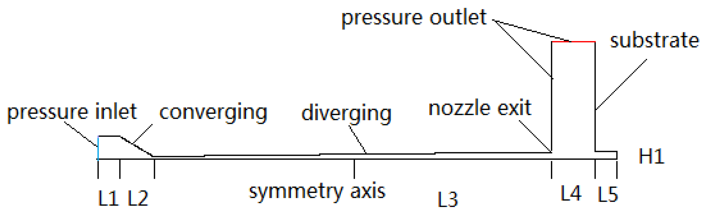
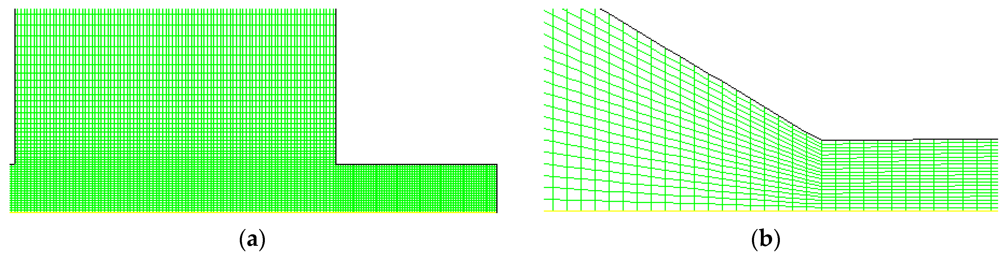
2.1. Physical Model and Simulation Domain

Numerical modeling was performed by using the commercial software FLUENT (version 16.4, ANSYS Company, Pittsburgh, PA, USA) to determine the flow field of driving gas inside and outside the nozzle, and subsequently the acceleration behavior of particles. Due to the geometric axial-symmetrical characteristic of flow in this study, a 2D axial-symmetric model was used for calculation. The physical calculation area is shown in Figure 1 based on the nozzle structure of the cold spray system. The geometric parameters and the working conditions are listed in Table 1.
The simulation domain and boundary conditions for calculation are shown in Figure 1. To spare computer resources, the simulation domain was simplified to a symmetric problem, which means that half of the geometry was taken into consideration. Along the x direction are the prechamber, converging part, diverging part, standoff distance and holes successively. The whole length of nozzle in the x direction is 225 mm, and the depth of hole varies. The gas flow in pre-chamber is set as Pressure-Inlet. The particles are injected from the central of pressure-inlet. Outside the nozzle, the boundary is set as Pressure-outlet. Other surfaces involved in the calculation are set as wall by default. The initial velocity of all particles is set to 10 m/s in the x+ direction. The wall boundary is considered to be stationary and adiabatic. The standard wall functions were adopted for near wall treatment, which works reasonably well for a broad range of wall-bounded flows. The nozzle wall boundary condition was set as reflect type, and the substrate wall boundary condition was set as trap type.

2.2. Numerical Simulation Method

The meshing was conducted with the quadrilateral mesh element, which is shown in Figure 2. The base mesh size is 0.1 mm and the goal mesh size is 2 mm. A prism layer mesher was used to mesh the boundary layer. The first mesh scale is 0.01 mm, increment ratio is 1.05 for boundary layer. The total mesh number of about 30,000 was adopted in these simulation works. The calculation result independency to mesh density was checked. The total mesh numbers of about 20,000, 30,000, 50,000 and 100,000 were checked. Under the 50,000 and 100,000 meshes scale, the results have no evident difference from 30,000 meshes scale. The y+ (5–60) was also checked to examine whether the (RNG, Renormalization Group) k-ε turbulent model can meet the requirement of near wall low Reynolds number flow or not, which can be found in literature [6]. The values of y+ are dependent on the resolution of the mesh and the Reynolds number of the flow, and are defined only in wall-adjacent cells. The result is not credible unless the value of y+ ranges from 5 to 60 (but not strictly limited to this value), unless the results of simulation are very similar to experimental results or theoretical results. All the numerical simulation results were checked and the value lies in this range.
The gas was compressed air and taken as an ideal and compressible one, the Cp is 1006.43 J/kg·K, the molecular mass is 28.966 g/mol. Based on above assumptions, the continuity, momentum and energy conservation equations in their Reynolds-average general conservation forms are used to include and account for the effect of turbulence in the flow field, and written as Equations (1)–(3). In this physical problem, the accuracy for solving the turbulent eddy is the most important factor to be considered. Thus the gas flow in Laval nozzle is considered to be (RNG) k-ε turbulent model, which was proposed by Yakhot et al. [7,8], written in the Equations (4) and (5). This turbulent model can accurately simulate the flow field of both high and low velocity gas flow.
Mass:
( ρ μ i ) x i = 0
Momentum:
x j ( ρ μ i μ j ) = x j [ μ e f f ( μ j x j + μ i x i ) 2 3 μ e f f μ k x k ] p x i
Energy:
x j ( ρ μ i μ j ) = x j [ μ e f f ( μ j x j + μ i x i ) 2 3 μ e f f μ k x k ] p x i
Turbulence energy:
x i ( ρ u i k ) = x i [ ( α k μ e f f k x i ) ] + μ i S 2 ρ ε
Turbulence energy dissipation:
x i ( ρ μ i ε ) = x i [ ( α ε μ e f f ε x i ) ] + C 1 ε ε k μ i S 2 C 2 ε ρ ε 2 k R
For compressible flow, the state equation of the ideal gas can be written as Equation (6).
p ρ = R T
k is k equation coefficient, ε is the turbulence energy dissipation coefficient, and μeff is the effective viscosity coefficient. Coefficient αT, αk and αε is the reciprocal of effective Prandt1 of energy k and ε equation respectively. S is the mean-velocity strain-rate tensor coefficient. Constant Cμ, C1ε and C2ε has the value of 0.085, 1.42 and 1.68 respectively. µ is viscosity of gas, Pa·s. R is gas constant.
Copper particles were used in this simulation with density of 8.9 g/cm3; the molecular mass is 64 g/mol, and the particle diameter is set to 10 μm and considered a spherical ball for all situations. The particle acceleration behavior for compressed air can be solved by Equation (7) using the model proposed by Morsi and Alexander [9] when the particles are considered to be spherical, dilute phase, as the particle loading rate is 1 g/s. This model was also used by Jodoin et al. [7] and Lupoi et al. [8] to calculate the particle velocity in the cold spraying process, and is suitable for this situation. It is assumed that heat conduction within a particle is neglected and the particle is therefore treated as isothermal. Fx is the correlation terms including effective mass: force, pressure gradient-induced force and thermophoretic force. In this study, the Fx and gx can be considered to be 0. The drag coefficient correlation equations are different for supersonic and subsonic flow. For quasi-spherical particles, the drag coefficient correlation can be written as Equation (9), in which Constant a1, a2 and a3 have the values listed in Table 2, calculated by Henderson et al. [10]. These constants were also used by Li et al. [11] and Tabbara et al. [12] to calculate the drag force of spherical and quasi- spherical particles in the cold spray process and can match the experimental results well.
d u p d t = F D ( u u p ) + g x ( ρ p ρ ) ρ p + F x
F D = 18 p ρ p d p 2 C D Re 24
C d = a 1 + a 2 Re p + a 3 Re p 2
Re p = ρ g d p | u p u g u g |
In above equation, FD is the drag force (N), Cd is drag force coefficient (N·m), ug is velocity of the gas flow (m/s), ρ is the gas density (g/cm3), ρp is the particles density (g/cm3). up is velocity of the particles, dp is the diameter of particle (μm).

2.3. Verification of Simulation Results

Pure copper plate was used as substrate, abraded with emery paper number 280 and 600 in sequence, then holes of different size were drilled on it. Three kinds of holes were drilled, each hole has the diameter 1000 μm depth 500 μm, diameter 500 μm depth 500 μm and diameter 200 μm depth 1000 μm respectively. Pure copper powder was used to form a coating in cold spraying. The morphology of the powder is shown in Figure 3. The cold spray system used to prepare the coating has the parameters listed in Table 1. The gas parameter in the pre-chamber is 3.0 MPa and 673 K. The compressed air was adopted as carrier gas. The transverse speed of the spray gun is 5 cm/s. The distance between nozzle exit and the substrate is about 25 mm.
The prepared cold spraying samples then were cut through the center of the holes to get the transverse surface using a spark-cutting method. The cross-section surface of the coating is abraded with sand paper of 220#, 500#, 800# and 1000#, then polished with polishing paste, rinsed with water and distilled with acethone, etched with 1% HCl for 5 s, then observed under the ULTRA55 FESEM (Carl Zeiss Microscopy GmbH, Jena, German).

2.4. Interaction between Particles in Cold Spray by LS-DYNA

The impacting behavior of particles on the substrate was modelled using LS-DYNA (971R, ANSYS Company, Pittsburgh, PA, USA) to investigate the reason for hole formation. The ALE formulation was used for solution based on the basic mass, momentum and energy conservation equations. The Johnson–Cook model was chosen as the material constitutive model, which is written in Equation (11), and a linear Mie-Gruneisen equation of state (EOS) was employed for the elastic behavior, which is written in Equation (12). The plane 162 shell element was adopted Tabbara et al. [13]. The gravity, friction and rebound force were neglected since the inertial force determines the erosion and deformation in the high velocity impacting process. The properties used for pure copper in the simulation are listed in Table 3 [14]. The particles were considered to be a solid sphere, and the calculation region for substrate was 5 times as the particles. More detailed information can be found elsewhere in the literature, e.g., Li et al. [15].
Coatings 07 00002 i001
P = C 0 + C 1 μ + C 0 μ + C 0 μ 2 + ( C 4 + C 5 μ + C 6 μ 2 ) E
E is the initial internal energy (J/kg·K). µ is the density ratio. C is the volume sonic velocity (m/s). P is the pressure loaded on materials (MPa).

3. Results

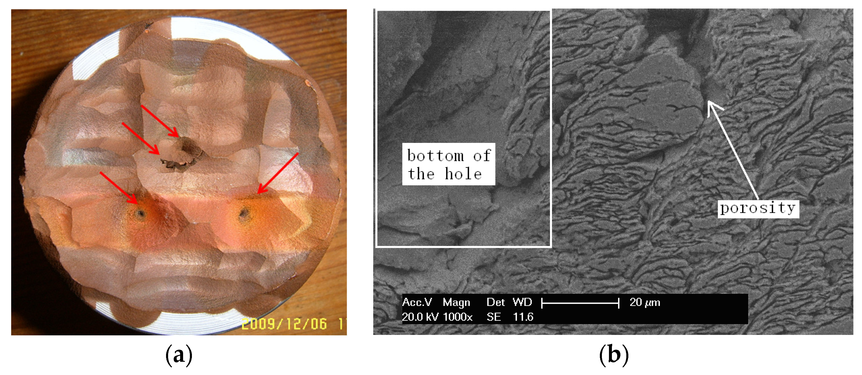
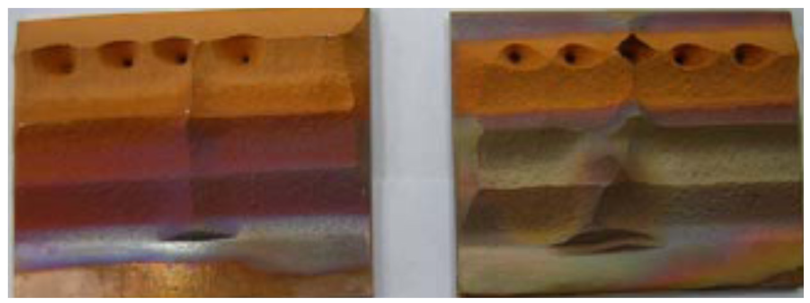
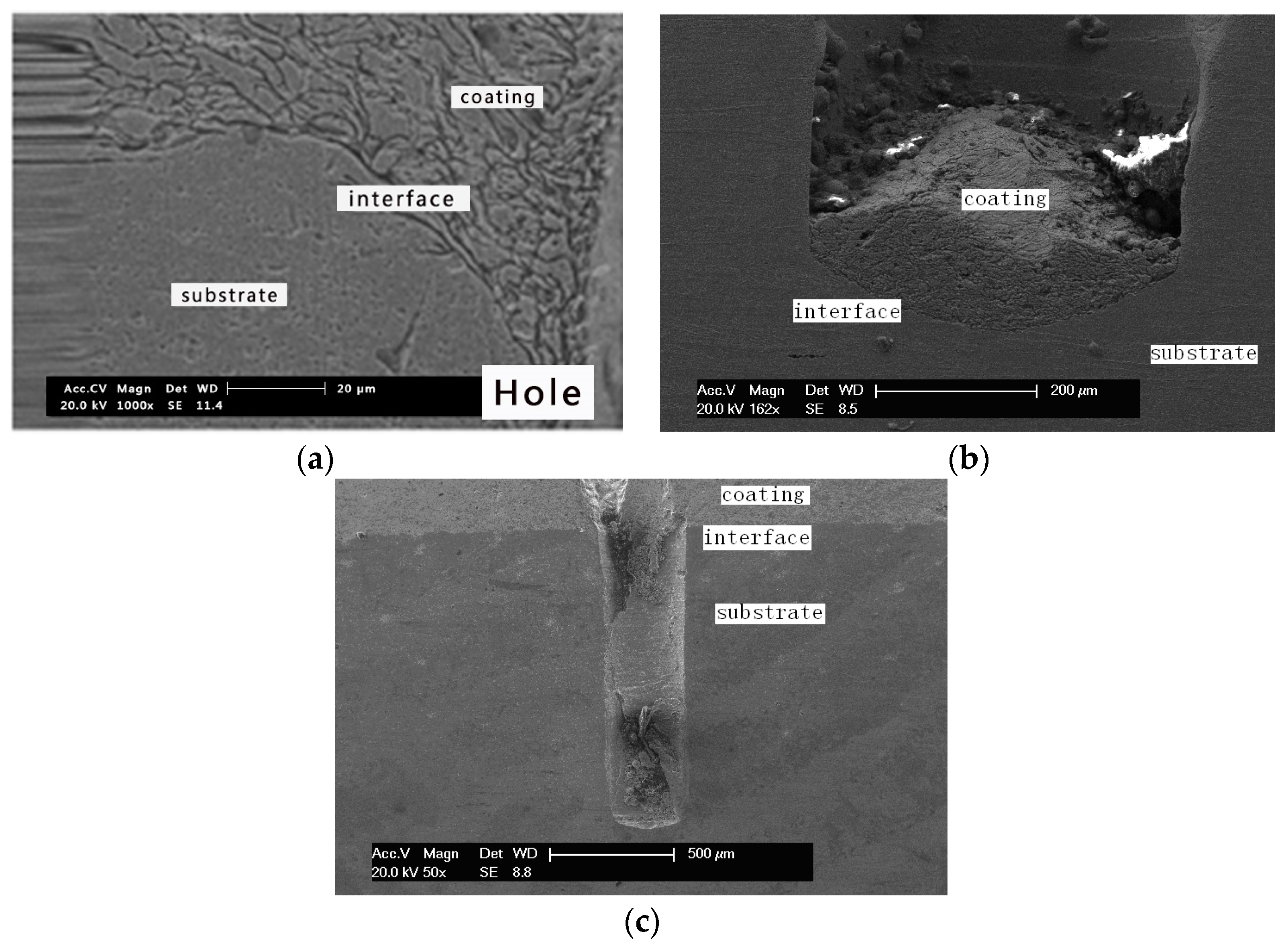
3.1. Characteristics of Thickness Coating around the Holes

Due to the limitation of funding and laboratory conditions in our institute, the depth of holes cannot be controlled precisely by the drilling machine. Only four kinds of holes were drilled in the copper substrate. As shown in Figure 4, the holes grow larger as the coatings become thicker during cold spraying process. For the wider one, the hole on the left is partially covered by the cold spraying copper coating. The wider hole (3 mm diameter) is fully filled by the copper coating. The bottom of rest holes are not covered by the copper coating. The cross-section morphology of the holes is shown in Figure 5. One of the holes was miss cut and the interface between coating and substrate around the hole cannot be found. It can be seen that the large hole with diameter 1000 μm and depth 500 μm can be replenished during cold spraying. No coating can be deposited in the small hole with diameter 200 μm and depth 500 μm. Also, partial coating can be deposited in the hole with diameter 500 μm and depth 500 μm, but it cannot be replenished during the deposition. It can be inferred that the deposition efficiency inside and outside the holes are different. Observed by the surface morphology of coating on the plane substrate, the roughness of cold spray coating is about 10 μm, which means that the coating is nearly with the same deposition efficiency during the spraying process. From a statistical perspective, the amount of metal particles for a unit area is the same, but the deposition efficiency is different for inside hole and outside hole. Then the growth rate outside the hole is different from inside the hole, which leads to the phenomenon in Figure 5.

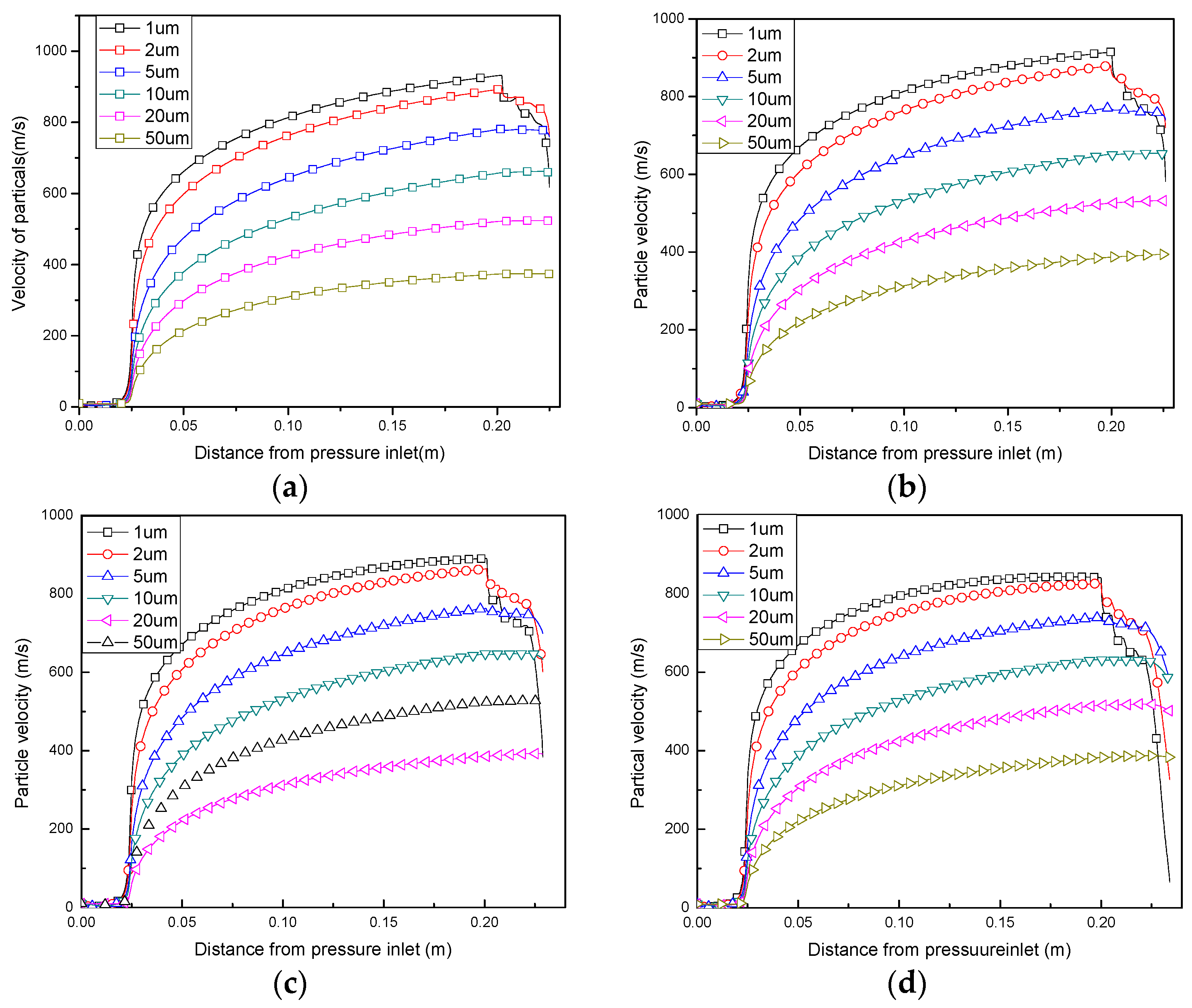
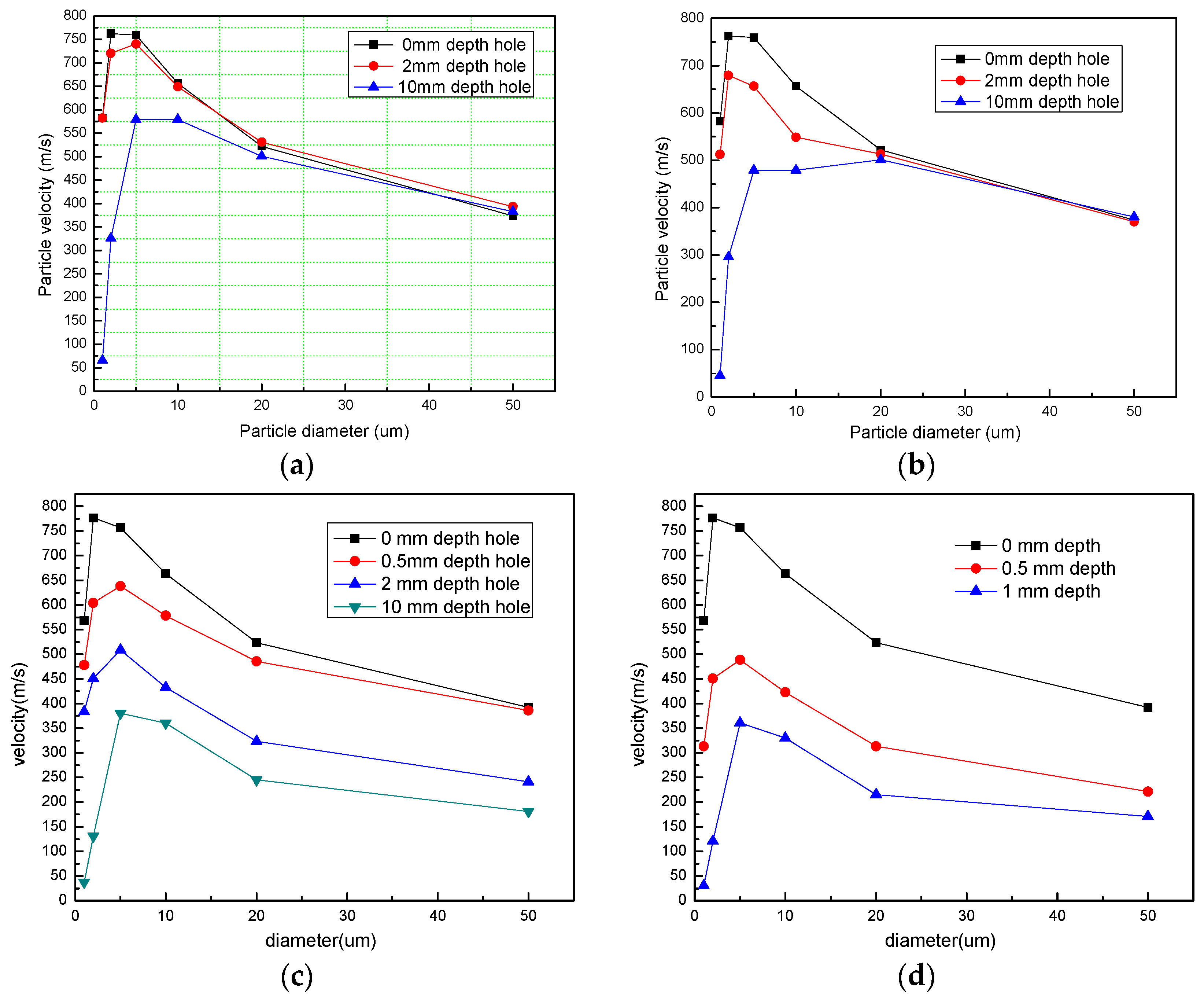
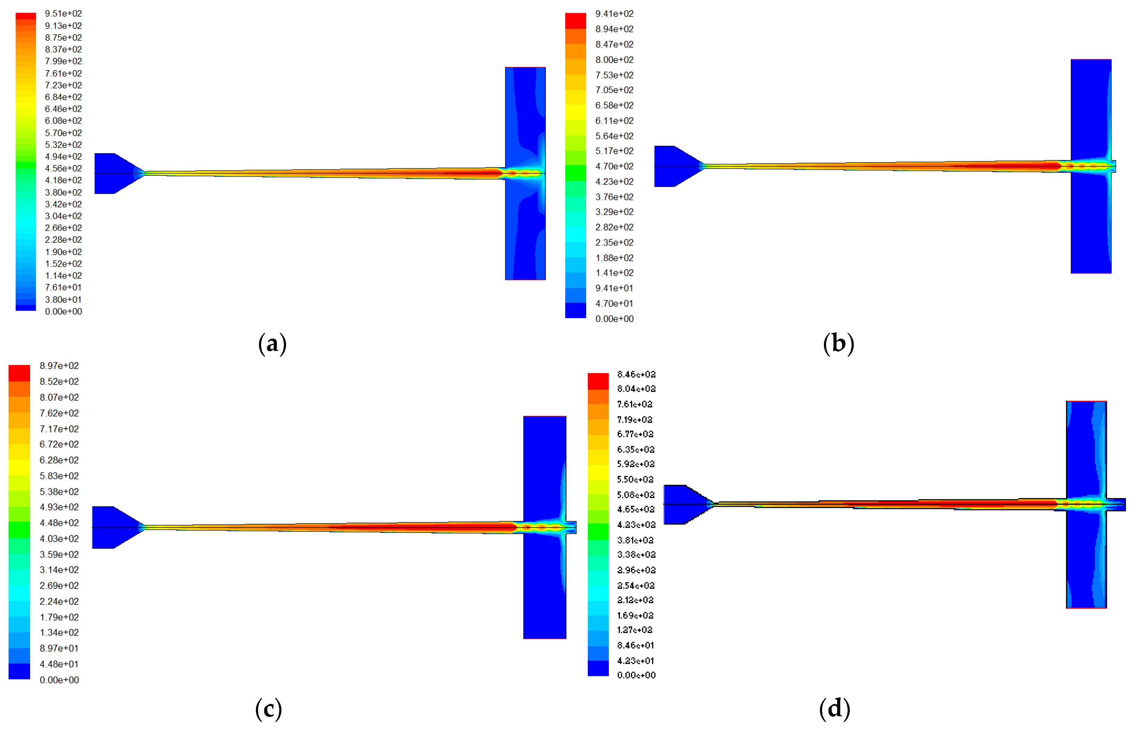
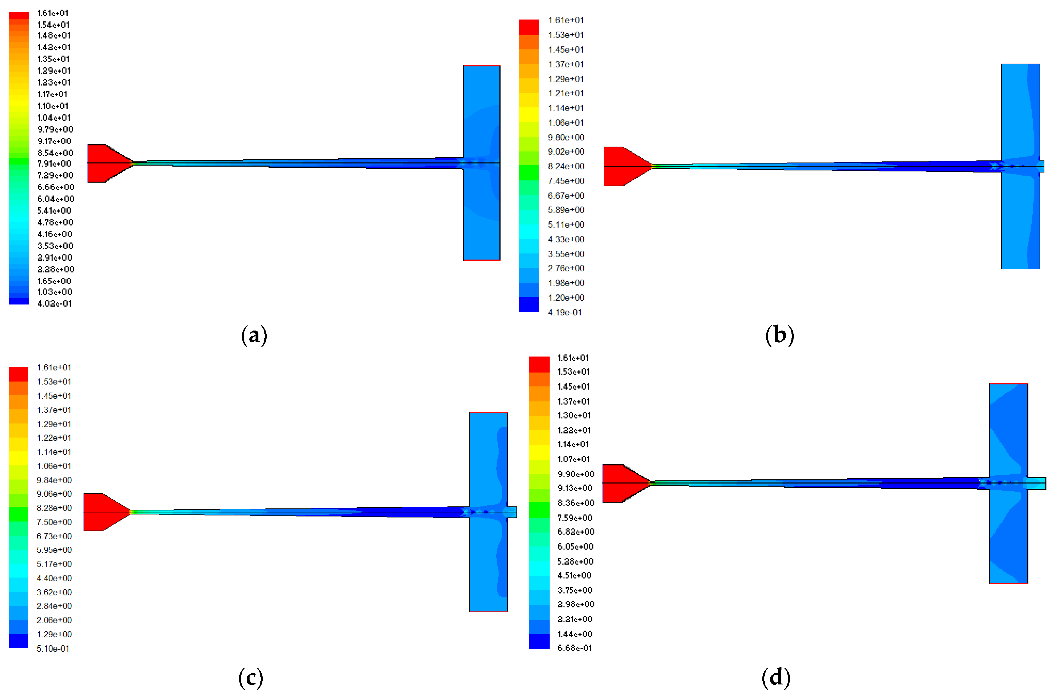
3.2. Particle Velocity in the Holes

In a cold spraying process, the final impacting velocity determines whether the particles deposit or not. The particle velocity then is determined by the gas flow inside and outside the nozzle, in actually the spraying parameters and structure of nozzle. A typical gas flow inside and outside the nozzle is shown in Figure 6 as the hole with 3 mm diameter and different depths. It can be seen that the hole has little effect on the gas flow field inside and outside the nozzle. A typical density distribution of gas inside and outside the nozzle is shown in Figure 7 as the hole with 3 mm diameter and different depth. The length of stationary gas becomes greater as the hole becomes deeper.
The acceleration behaviors of particle in the flow field are shown in Figure 8. The behaviors of all particles vary little as they travel to the substrate, except the small particle decelerates largely while it travels in deeper hole. The particles with diameter larger than 10 um vary little as they travel to the substrate. The particles with diameter smaller than 5 um fluctuates with the gas flow. And the small particles decelerate significantly as they travel to the substrate. The final impacting velocity of the 1 μm decelerates to about 80 m/s as the hole is 10 mm depth, which is about 600 m/s before the plane substrate. Final impacting velocity of different diameter particles before the holes with different holes diameter are shown in Figure 9. The final impacting velocity is the particle velocity finally impacting to the substrate. Generally, the final impacting velocity increases as the particle diameter increases when the diameter is small than 5 μm. Then the final impacting velocity decreases as the particle diameter increases when the diameter is larger than 10 μm. There is a diameter range for the particle to exceed the critical velocity. It can be seen from Figure 10 that most of the particle with diameter between 5 and 20 μm can exceed the critical velocity according to literature (550 m/s for copper particle) [16,17,18]. It can be inferred that the deposition efficiency will increase as more particles attain the critical velocity. As the hole becomes deeper and narrower, the particle diameter range becomes narrow. No particle can attain the critical velocity as the hole is 0.2 mm diameter because all the particle velocity is less than 500 m/s. It is apparent that the deposition efficiency inner and out the hole is different, the deposition efficiency out the hole is higher than that of inner the hole.

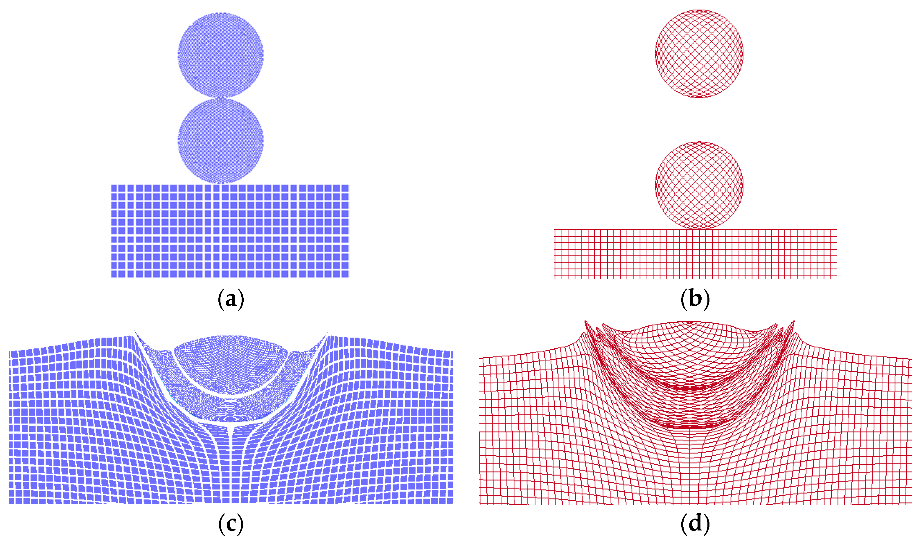
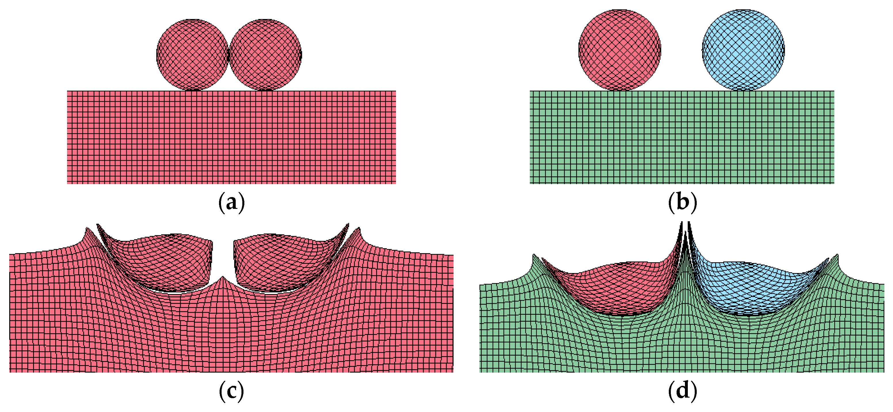
3.3. Particle Interaction during Impacting onto the Substrate

So far, little is known about why particles exceeding critical velocity can deposit on substrate. Researchers believed that the intimate bonding between particles occurs when oxide is extruded during impaction. In this work, interaction between particles is taken into consideration to investigate the reason for the formation of holes and bonding defects. The final deformation of two particles and its initial states at different distances impacting on the substrate at an identical position is shown in Figure 10a-d. It can be seen that the first particle has a much larger deformation ratio than the second one in both cases. The deformation of the second particle with an interval as shown in Figure 10b is much larger than that of without interval as shown in Figure 10a. The deformation of the second particles is influenced by the interval distance.
It can be seen from Figure 11 that there is a gap between deposited particles if two particles impact the substrate side by side, which means that repellant force between the particles perpendicular to the impaction direction will lead to porosity if they are too close, as shown in Figure 11a. A proper distance can produce a roll-up, which will significantly improve the bonding strength as shown in Figure 11b.
The hole can be formed on the coating as the powder feeding rate is 3.5 g/s as shown in Figure 12a. The microstructure of the hole bottom is shown in Figure 12b, it can be seen that at the hole bottom the particles bonding quality is much bad. This verify the hypothesis that the holes origin from location of bonding defection.

4. Discussion

Firstly, the macrophotograph of cold sprayed coating indicates that the cold spraying coating cannot be deposited in narrow and deep holes. The size limitation in this study was not discussed. It can be inferred that the limitation might be influenced by the length ratio between width and depth.
It is apparent that as the diameter of hole becomes narrower, the final impacting velocity of the particle becomes lower. As the holes become narrower and deeper, the ratio of particles with final impacting velocity higher than the critical velocity becomes lower. Then, the deposition efficiency inside the hole is lower than that of the plane substrate. According to uniform morphology of a cold spraying coating, the density of particles impacting the surface within a unit area is constant. Thus, the deposition efficiency difference inside the hole and the substrate leads to different thickness growth rate, which lead to deeper holes. According to literature, the critical velocity is about 550 m/s for copper particles to build up coating in cold spraying. The coating can be deposited in the hole, as the hole is 500 μm in diameter and 500 μm in depth. The coating cannot be deposited in the hole as the hole is 500 μm in diameter and 2000 μm in depth. Also, the coating cannot be deposited in the hole as the hole is 200 μm in diameter and 500 μm in depth. All these simulation results are very consistent with the experimental results shown in Figure 8. There is no doubt that the stationary gas in the hole can decelerate the particle to such a low velocity. For small particles, the inertia of the particle is small and can be changed easily by the gas flow. For large particles, the diameter of the hole is 200 μm, so the particle needs to pile out a large part of the gas in the hole. It worth noting that the gas in the nozzle is very diluted, and the gas in the hole is very dense.
It can be inferred that the dynamic energy of the second particle converts to the deformation ability of the first particle in a successive impacting case. The mechanical property of metal in undergoing plastic deformation is significantly different from its original state. To some extent, the particle is very soft when it undergoes the plastic deformation, so the second particle can penetrate more deeply while experiencing less deformation itself. According to previous studies, high quality bonding mainly depends on sufficient deformation of particles in impaction. This is not good for coating formation because it will lead to a lower bonding strength when coating is built up. This is also a defect hard to distinguish from normal bonding particles, since the particles will be realigned during subsequent impaction [19,20]. More seriously, these kinds of defects will be eroded by subsequent impacting particles. For the particles impacting onto the substrate side by side, a shock wave will be formed between them. The shock wave will repel the particles away from each other. Instead of forming perfect bonding, this location become a defect (porosity) and will influence the subsequent impaction since the pore will absorb part of the energy of the particle. A hypothesis can be proposed from the above data and analysis. The repellant force between the particles perpendicular to the impaction direction will lead to porosity if they are too close. A much lower flattening ratio occurs for the succeeding particle if the particles are too close at an identical location, because the momentum energy of second particle will contributes to the former particle’s deformation. A high probability of above two phenomena resulting from high powder feeding rate will form the original hole, which will grow larger and larger once it is formed. It is very important to control the feeding rate of powder, but the up limitation is yet to be determined by further simulation and experimental investigation.

5. Conclusions

Based on the results of this paper the following conclusions can be drawn.
  • A hypothesis for the original formation reason of holes can be proposed: particles are too close when they impact onto the substrate. The repellant force between the particles perpendicular to the impaction direction will lead to porosity if the particles are too close. A much lower flattening ratio occurred for succeeding particles if they were too close to the same point, because the momentum energy contributes to the former particle’s deformation. There is a high probability of the above two phenomena, resulting from high powder-feeding rate, forming the original hole.
  • The holes cannot be filled up for deceleration of the compressed layer and collision between particles and inner face of hole. In relatively wider holes, coating can be deposited in the bottom, while in relatively narrower holes, coating cannot be deposited. The deposition efficiency is much lower inside the hole than on the plane substrate, which will lead to hole growth.

Acknowledgments

This work had been guided by the engineer Yongze Xu of CDAJ Company (Japan).

Author Contributions

Hongren Wang and Lukuo Xing conceived and designed the experiments; Xiangbo Li performed the experiments and analyzed the data; Guosheng Huang wrote the paper.

Conflicts of Interest

The authors declare no conflict of interest.

References

  1. Alkhimov, A.P.; Kosarev, V.F.; Klinkov, S.V. The features of cold spray nozzle design. J. Therm. Spray Technol. 2001, 10, 375–381. [Google Scholar] [CrossRef]
  2. Henderson, C.B. Drag coefficients of spheres in continuum and rarefied flows. AIAA J. 1976, 14, 707–708. [Google Scholar] [CrossRef]
  3. Moridi, A.; Hassani-Gangaraj, S.M.; Guagliano, M.; Dao, M. Cold spray coating: Review of material systems and future perspectives. Surf. Eng. 2014, 36, 369–395. [Google Scholar] [CrossRef]
  4. Astarita, A.; Genna, S.; Leone, C.; Memola, C.M.F.; Paradiso, V.; Squillace, A. Laser cutting of aluminum sheets with a superficial cold spray titanium coating. Key Eng. Mater. 2014, 611, 794–803. [Google Scholar] [CrossRef]
  5. Astarita, A.; Carrino, L.; Durante, M.A.; Formisano, A.; Langella, F.M.C.; Minutolo, P.V.; Squillace, A. Experimental study on the incremental forming of coated aluminum alloy sheets. Key Eng. Mater. 2014, 622, 398–405. [Google Scholar] [CrossRef]
  6. Grujicic, M.; Saylor, J.R.; Beasley, D.E. Computational analysis of the interfacial bonding between feed powder particles and substrate in cold gas dynamic spray process. Appl. Surf. Sci. 2003, 319, 211–227. [Google Scholar] [CrossRef]
  7. Widener, C.A.; Carter, M.J.; Ozdemir, O.C.; Hrabe, R.H.; Hoiland, B.; Stamey, T.E.; Champagne, V.K.; Eden, T.J. Application of high-pressure cold spray for an internal bore repair of a navy valve actuator. J. Therm. Spray Technol. 2016, 25, 193–201. [Google Scholar] [CrossRef]
  8. Yakhot, V.; Steven, A. Renormalization group and local order in strong turbulence. Nuclear Phys. B 2012, 2, 417–440. [Google Scholar] [CrossRef]
  9. Li, S.; Muddle, B.; Jahedi, M. A numerical investigation of the cold spray process using underexpanded and overexpanded jets. J. Therm. Spray Technol. 2012, 21, 108–120. [Google Scholar] [CrossRef]
  10. Morsi, S.A.; Alexander, A.J. An investigation of particle trajectories in two-phase flow systems. J. Fluid Mech. 1972, 55, 193–208. [Google Scholar] [CrossRef]
  11. Jodoin, B.; Raletz, F.; Vardelle, M. Cold spray modeling and validation using an optical diagnostic method. Surf. Coat. Technol. 2006, 200, 4424–4432. [Google Scholar] [CrossRef]
  12. Lu, O.N. Powder stream characteristics in cold spray nozzle. Surf. Coat. Technol. 2012, 206, 1069–1076. [Google Scholar]
  13. Li, W.Y.; Liao, H.; Douchy, G.; Coddet, C. Optimal design of a cold spray nozzle by numerical analysis of particle velocity and experimental validation with 316L stainless steel powder. Mater. Des. 2007, 28, 2129–2137. [Google Scholar] [CrossRef]
  14. Li, W.Y.; Liao, H.; Wang, H.T.; Li, C.J.; Zhang, G.; Coddet, C. Optimal design of a convergent-barrel cold spray nozzle by numerical method. Appl. Surf. Sci. 2006, 253, 708–716. [Google Scholar] [CrossRef]
  15. Li, W.Y.; Liao, H.L.; Li, C.J. Numerical simulation of deformation behavior of Al particles on Al substrate and effect of surface oxide films on interfacial bonding in cold spraying. Appl. Surf. Sci. 2007, 253, 5084–5091. [Google Scholar] [CrossRef]
  16. Tabbara, H.; Gu, S.; Cartney, P. Study on process optimization of cold gas spraying. J. Therm. Spray Technol. 2010, 20, 608–620. [Google Scholar] [CrossRef]
  17. Tabbara, H.; Gu, S. Computational modeling of titanium particles in warm spray. Comput. Fluids 2012, 44, 358–368. [Google Scholar] [CrossRef]
  18. Li, W.Y.; Li, C.J. Optimal design of a novel cold spray gun at a limited space. J. Therm. Spray Technol. 2005, 14, 391–396. [Google Scholar] [CrossRef]
  19. Cadney, S.; Brochu, M.; Richer, P. Cold gas dynamic spraying as a method for free forming and joining materials. Surf. Coat. Technol. 2008, 202, 2801–2806. [Google Scholar] [CrossRef]
  20. Pattison, J.; Celotto, S.; Morgan, R. Cold gas dynamic manufacturing: A non-thermal approach to freeform fabrication. Int. J. Mach. Tools Manuf. 2007, 47, 627–634. [Google Scholar] [CrossRef]
Figure 1. Schematic diagram of axial-symmetrical computational domain and boundary conditions.
Coatings 07 00002 g001
Figure 2. Schematic diagram of quadrilateral meshing strategy for computational domain (a) substrate near the hole, (b) cross-section of nozzle throat.
Coatings 07 00002 g002
Figure 3. Morphology of pure copper powder used for preparing coating around the holes.
Coatings 07 00002 g003
Figure 4. Macrophotograph of copper coating around the different size predrilled holes on copper substrate, including 0.2, 0.05, 1 and 3 mm.
Coatings 07 00002 g004
Figure 5. Coating deposited on the bottom of the holes and around the holes with different size holes, (a) diameter 1000 μm and depth 500 μm, (b) diameter 500 μm and depth 500 μm, and (c) diameter 200 μm and depth 1000 μm.
Coatings 07 00002 g005
Figure 6. Velocity of gas inner and out of the nozzle with the holes diameter of 3 mm and depth of (a) 0 mm, (b) 2 mm, (c) 5 mm and (d) 10 mm in the substrate.
Coatings 07 00002 g006
Figure 7. Density of gas inner and out of the nozzle with the holes diameter of 3 mm and depth of (a) 0 mm, (b) 2 mm, (c) 5 mm and (d) 10 mm in the substrate.
Coatings 07 00002 g007
Figure 8. Acceleration behavior of particles in the flow field before the holes with diameter of 3 mm and depth of (a) 0 mm, (b) 2 mm, (c) 5 mm and (d) 10 mm in the substrate.
Coatings 07 00002 g008
Figure 9. Final impacting velocity of different diameter particle before the holes with different holes diameter of (a) 3 mm, (b) 1 mm, (c) 0.5 mm and (d) 0.2 mm in the substrate.
Coatings 07 00002 g009
Figure 10. Impaction of two particles onto substrate at an identical position: (a) original status without interval (0 μm distance), (b) original status with interval (10 μm distance), (c) final deformation without interval (0 μm distance) and (d) final deformation with interval (10 μm distance).
Coatings 07 00002 g010
Figure 11. Final deformation of impaction of two particles onto substrate in parallel position: (a) original status without space (0 μm), (b) original status with space (10 μm), (c) final deformation without space (0 μm) and (d) final deformation with space (10 μm).
Coatings 07 00002 g011
Figure 12. Characteristic of self-growth hole in cold spraying copper coating: (a) themacrophotograph of a copper coating on an aluminum module; (b) the bottom morphology of the hole.
Coatings 07 00002 g012
Table 1. Summary of geometric parameters and working conditions of the cold spray system.
Geometric Parameters and Working ConditionsValue
D1 (pre-chamber diameter)20 mm
D2 (throat diameter)2 mm
D3 (nozzle exit diameter)6 mm
L1 (pre-chamber length)10 mm
L2 (converging length)15 mm
L3 (diverging length)180 mm
L4 (standoff distance from nozzle exit to substrate)20 mm
L5 (depth of hole)0, 2, 5, 10 mm
H1 (diameter of hole)0.5, 1, 3 mm
Pressure in pre-chamber3.0 MPa
Temperature in pre-chamber673 K
Powder feeding rate1 g/s
Table 2. Drag force coefficient of dilute spherical metal particles in airflow.
Rea1a2a3
Re < 0.1024.00
0.1 < Re < 1.03.6922.730.0903
1.0 < Re < 10.01.22229.1667−3.8889
10.0 < Re < 100.00.616746.5−116.67
100.0 < Re < 1000.00.364498.33−2778
1000.0 < Re < 5000.00.357148.62−4.75 × 10⁵
5000.0 < Re < 10000.00.46−490.4565.787 × 105
10000.0 < Re < 50000.00.5191−1662.55.4167 × 105
Table 3. Johnson–Cook model properties used for pure copper in the simulation.
MaterialCopper
Modulus of elasticity, E (N/m2)0.124 × 1012
Poison’s ratio, n0.34
Density, ρ (kg/m3)7900
Yield stress, A (MPa)90
B (MPa)292
n0.31
C0.025
Reference strain rate, 0 (1/s)1.00
m1.09
Tmelt(K)1356
T0 (K)293
Specifc heat, Cp (J/kg·K)383
Inelastic heat fraction, p0.90
D10.00
D20.00
D30.00
D40.00
D50.00

