Article

Tribological and Wear Performance of Carbide Tools with TiB2 PVD Coating under Varying Machining Conditions of TiAl6V4 Aerospace Alloy

by
Jose Mario Paiva
1,2,*,
Mohamed Abdul Monim Shalaby
3,
Mohammad Chowdhury
1,
Lev Shuster
4,
Sergey Chertovskikh
4,
Danielle Covelli
5,
Edinei Locks Junior
1,
Pietro Stolf
1,
Amr Elfizy
6,
Carlos Alberto Schuch Bork
1,7,
German Fox-Rabinovich
1 and
Stephen Clarence Veldhuis
1
1
McMaster Manufacturing Research Institute (MMRI), Department of Mechanical Engineering, McMaster University, 1280 Main Street West, Hamilton, ON L8S4L7, Canada
2
Department of Mechanical and Materials Science, Catholic University of Santa Catarina, Rua Visconde de Taunay, 427-Centro, Joinville-SC 89203-005, Brazil
3
Department of Design and Production, Technical Research Center, Cairo 11461, Egypt
4
Department of Mechanical Engineering, Ufa State Aviation Technical University (USATU), Ufa 450008, The Republic of Bashkortostan, Russian Federation
5
Biointerfaces Institute, McMaster University, ETB 422, 1280 Main Street West, Hamilton, ON L8S0A3, Canada
6
1000 Marie-Victorin Blvd., Longueuil, QC J4G1A1, Canada
7
Instituto Federal de Educação, Ciência e Tecnologia Sul Riograndense (IFSul)—Campus Sapucaia do Sul, Piratini CEP 93216-120, Brazil
*
Author to whom correspondence should be addressed.
Coatings 2017, 7(11), 187; https://doi.org/10.3390/coatings7110187
Submission received: 5 September 2017 / Revised: 22 October 2017 / Accepted: 1 November 2017 / Published: 4 November 2017
(This article belongs to the Special Issue Coatings for Cutting Tools)

Abstract

:
Tribological phenomena and tool wear mechanisms during machining of hard-to-cut TiAl6V4 aerospace alloy have been investigated in detail. Since cutting tool wear is directly affected by tribological phenomena occurring between the surfaces of the workpiece and the cutting tool, the performance of the cutting tool is strongly associated with the conditions of the machining process. The present work shows the effect of different machining conditions on the tribological and wear performance of TiB2-coated cutting tools compared to uncoated carbide tools. FEM modeling of the temperature profile on the friction surface was performed for wet machining conditions under varying cutting parameters. Comprehensive characterization of the TiB2 coated vs. uncoated cutting tool wear performance was made using optical 3D imaging, SEM/EDX and XPS methods respectively. The results obtained were linked to the FEM modeling. The studies carried out show that during machining of the TiAl6V4 alloy, the efficiency of the TiB2 coating application for carbide cutting tools strongly depends on cutting conditions. The TiB2 coating is very efficient under roughing at low speeds (with strong buildup edge formation). In contrast, it shows similar wear performance to the uncoated tool under finishing operations at higher cutting speeds when cratering wear predominates.

1. Introduction

Titanium alloys are widely used for components in the aerospace industry, due to their good combination of mechanical properties (high temperature strength, high ductility and toughness), and corrosion resistance at elevated temperatures [1]. However, machining these alloys poses a challenge due to the high temperatures generated during cutting as a result of intensive adhesion of the workpiece material to the tool surface. These characteristics make titanium alloys difficult-to-machine materials [2]. One of the most crucial issues of cutting tool behavior during machining of Ti is the low efficiency of the most widely used PVD coating such as TiAlN. This can be related to the high hardness and residual stress level of this family of coatings [3]. Therefore, the coating layer tends to peel off of the tool surface during machining of the sticky and strong materials such as Ti alloys [4]. Due to this phenomenon, the uncoated carbide tools often outperform coated tools in this application [5]. In contrast, the TiB2 coating with optimized set of characteristics shows much promise for the machining of Ti alloys [6]. However, cutting phenomena vary significantly during machining of Ti alloys under different machining conditions, such as those widely used in industry roughing and finishing operations [7,8].
For that reason, it is of special interest to investigate the effect of the machining conditions on the wear performance of TiB2-coated cutting tool in comparison to the uncoated cemented carbide tools.
As outlined above, a general feature of titanium alloy cutting is a high cutting temperature and, consequently, a short tool life [9]. Cutting speed applied during machining has a great effect on the temperature generated at the tool chip interface. Therefore, it is quite reasonable to expect different tribological/wear performance of TiB2-coated carbide tool.
A major phenomenon during machining of Ti alloys at a lower cutting speed is an intensive buildup edge formation [10]. Previous research shows that the TiB2 coating with optimized properties can be very efficient when a strong buildup edge forms [11]. This is typical for rough turning operation at low speeds [12]. However, at the higher speeds (at finishing operation), the buildup is removed from friction surface [13] and cratering becomes predominant [14]. Presumably, efficiency of the TiB2 coating could strongly vary under different cutting speeds.
Therefore, the goal of the paper is to relate different machining conditions with various dominating wear mechanisms, to the tribological and wear performance of the TiB2-coated tool. Three types of machining conditions were studied in this research: (1) rough turning at a low/medium cutting speed (45 m/min) with strong buildup edge formation; (2) finish turning using a higher speed of 80 m/min (with noticeable buildup formation); and (3) high speed finish turning at 150 m/min (without noticeable buildup edge formation) but with strongly chained diffusion processes (cratering) related to the high temperature at the chip/tool interface [15].

2. Finite Element Process Modeling

The finite element process modeling (FEM) is essential in evaluating cutting conditions, such as temperature profiles within the cutting zone. This is a critical step in understanding tool wear mechanisms. During Finite Element Modeling (FEM) for metal cutting, difficulty arises from severe plastic deformation of the metal, which results in extreme tribological conditions at the tool-workpiece interfaces [16]. One of the major challenges posed to modeling and simulation of the temperature into the cutting zone during machining of Ti alloys under wet conditions, is due to the complexity of the machining processes. In this case, modeling metal machining during turning requires a fundamental understanding of the deformation conditions in the relevant deformation zones, strain rates, as well as the friction conditions at the tool-work-piece interface. The cutting temperature profile is critical for understanding and controlling the machining process [17].

Research Methodology

The novelty of our modeling presented in this paper is the analysis of cutting temperatures within the cutting zone under wet conditions (flood coolant).
The modeling was performed with Third Wave Systems AdvantEdge™ simulation software (Version 7.1), which integrates advanced finite element models appropriate for machining operations. A continuous method for the formation of continuous chips was developed through cutting length of 3 mm. The workpiece material was TiAl6V4, and its mechanical properties were obtained using the FEM program database. The input parameters entered into the code as well as the contact conditions are given in Table 1.
The Johnson-Cook phenomenological constitutive model was used for FEM modeling of cutting temperature calculation modeling (2D model) [18]. This model describes the workpiece material behavior, considering the separated effects of strain hardening and thermal softening (Equation (1)).
σ ¯ = [ A + B ( ε ) n ] × [ 1 + C ln ( ε ˙ ε ˙ 0 ) ] × [ 1 ( T T r T m T r m ) ]
where
  • A: yield stress of the material under reference deformation conditions (MPa);
  • B: strain hardening constant (MPa);
  • n: strain hardening coefficient;
  • C: strain rate strengthening coefficient;
  • m: thermal softening coefficient;
  • T: deformation temperature;
  • Tr: room temperature;
  • Tm: melting temperature of the material;
  • ε: reference strain rate (1/s);
  • 𝜀̇: equivalent plastic strain normalized with a reference strain rate;
  • 𝜀̇0: plastic equivalent strain.
The cutting edge was defined ideally rigid, according to CNGG 432 Grade K313 (Kennametal). The cutting parameters and tool code geometry used in the simulation are listed in Table 2.
The 2D models of temperature at the cutting zone are presented in Figure 1a–c. FEM modeling shows the cutting edge temperature distribution for the three different cutting conditions tested. It can be seen that temperatures on the both rake and flank surfaces for the area close to the cutting edge are around 650–700 °C at rough turning conditions (Figure 1a). However, the maximum cutting temperature rises up to 800 °C and 950 °C at the speeds of 80 m/min (Figure 1b) and 150 m/min (Figure 1c) correspondingly.
This is due to the variability of cutting conditions during the cutting process. The effect of different cutting conditions on the tool wear performance will be discussed in detail in the “Results and Discussions” Section.

3. Experimental Procedure

The TiB2 was deposited in DC magnetron sputtering from a stoichiometric TiB2 target. The parameters of deposition are presented elsewhere [10]. The properties of the TiB2 coating are shown in Table 3. The coating was deposited on cemented carbide (WC/6% Co) Kennametal turning inserts—grade K313 (CNMG432 and CNGG432FS), with the following geometry characteristics: back rake angle, λ0 = −5; clearance angle, α0 = 5°; cutting edge angle, β0 = 90°; rake angle, y0 = −5°; side cutting edge angle, χr = 95°; and nose radius, Rε = 0.8 mm.
The machining experiments of TiAl6V4 aerospace alloy were performed in a NAKAMURA SC450 turning machining (Nakamura company, Hakusan Ishikawa, Japan) center. The turning tests were conducted for rough and finishing operations under wet cutting conditions. The cutting fluid was applied at a flow rate of 14 L/min via a nozzle positioned directly above the cutting tool and directed toward the tool lip. The cutting fluid was semi-synthetic XTREME CUT 290 (Qualichem, Salem, VA, USA), typically recommended for machining aerospace alloys such as TiAl6V4. The cutting conditions are presented in Table 2. These cutting parameters were selected according to standards widely used in industry for the machining of aerospace alloys in roughing and finishing operations. The tool life criterion was set to a flank wear of 0.3 mm. During the cutting test, the tool flank wear was measured using an optical microscope (TM, Mitutoyo, Kawasaki, Japan). Cutting tests were repeated three times for each cutting test condition. Flank wear was measured three times for each insert. The scatter of the flank wear values was found to be approximately 5%.
The coefficient of friction vs. temperature was determined with the aid of a specially designed apparatus described in [21]. This apparatus was designed to mimic the adhesive interaction of the tool/workpiece interface that occurs during machining conditions. A rotating sample of the coated substrate was placed between two polished specimens made of work-piece material (TiAl6V4 alloy). To simulate tool/friction conditions, the specimens were heated by resistive heating to temperatures ranging from 25 °C to 1000 °C. A force of 2400 N was applied to achieve plastic strain in the contact zone. The coefficient of friction value was calculated, as a ratio between the shear strength of the adhesive bonds and the normal contact stress developed at the interface. Three trials were performed for each coating. The estimated magnitude of error in calculating the coefficient of friction was 5%.
Progressive wear studies have been performed for uncoated and coated cutting inserts under both roughing and finishing conditions. After each 600 m length of cut, the inserts were studied by Alicona Infinite Focus 3D optical microscope (Alicona Imaging, Raaba, Austria) and scanning electron microscope (Vega 3-TESCAN, Brno Kohoutovice, Czech Republic). The 3D analysis of worn tools was performed on Alicona by plotting the profile of rake and flank surface wear of cutting inserts. Based on the combination of small depth and vertical scanning, the 3D optical system with Focus-Variated was used to generate a three-dimensional topography with real color information. In order to characterize the topography of cutting tools, a 3D-motif analysis was adopted to generate the regions of cutting tools out of the measured data. According to ISO 25178-2 [22], a 3D-motif is defined as a valley and/or peak (hill) that includes the critical points (peaks, valleys and saddle points) and the critical lines (ridge lines and course lines). This analysis has been performed through of comparison between the worn and unworn cutting edge with a magnification of 50×. The Volume and square wear modes were measured and the total amount of BUE and its volume outlined with different colors. Besides the surface profiles and true color information, the whole areas of the cutting tool can be measured in 3D data. These values have been reported in the Origin analytical software system to establish statistical data. The measurement was repeated three times for each insert. The average error was around 5%. In addition, the high-resolution scanning electron microscope (SEM) was used for the detailed inspection of the worn cutting tools.
The formation of tribo-oxides was evaluated through of X-ray Photoelectron spectroscopic (XPS, Quantera II, PHI, Chanhassen, MN, USA) analysis on both flank and rake surface for TiB2-coated inserts. A Physical Electronics (PHI) Quantera II (2017 Physical Electronics, Inc., Chanhassen, MN, USA) equipped with a hemispherical energy analyzer and an Al anode source for X-ray generation and a quartz crystal mono-chromator for focusing the generated X-rays was used to collect XPS data. A monochromatic Al Kα X-ray (1486.7 eV) source was operated at 50 W/15 kV. The system base pressure was as low as 1.0 × 10⁻⁹ Torr with an operating pressure that did not exceed 2.0 × 10⁻⁸ Torr. Before any spectra were collected, the samples were sputter-cleaned for 4 min using a 4-kVAr+ beam. A 200-μm beam was used for all data collected on the samples. Pass energy of 280 eV was used to obtain all survey spectra, while a pass energy of 55 eV was used to collect all high-resolution data. All spectra were obtained at a 45° take off angle. A dual beam charge compensation system ensured neutralization of all samples. All high-resolution data was calibrated by setting the C1s C–C peak at 284.8 eV. All data analysis was performed using PHI Multipak version 9.4.0.7 software.

4. Results and Discussion

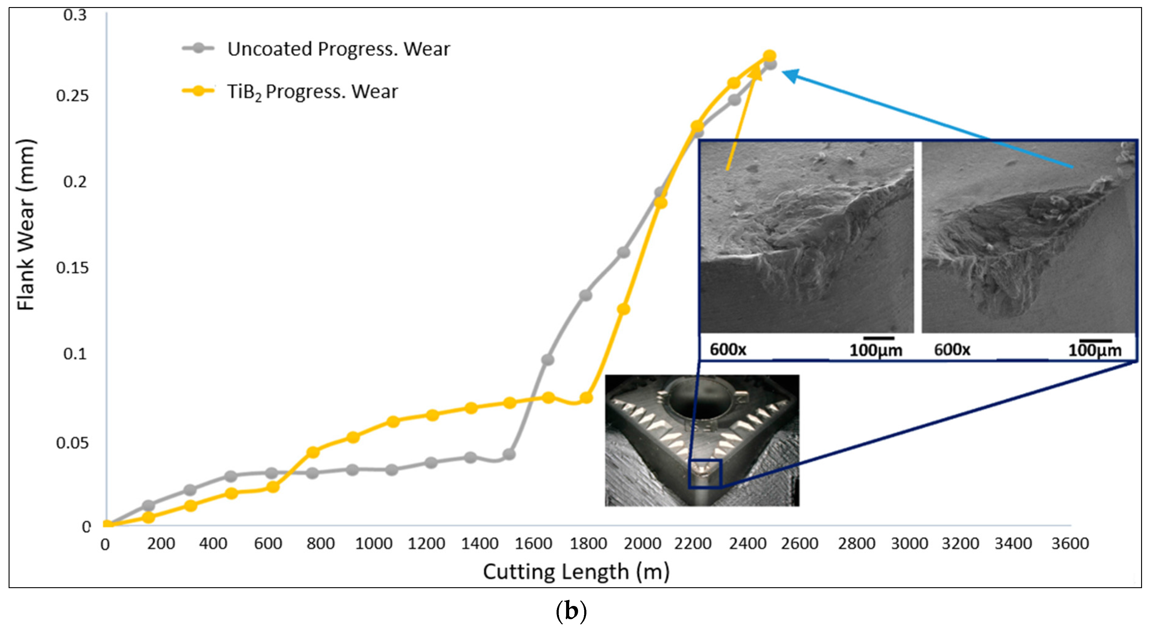
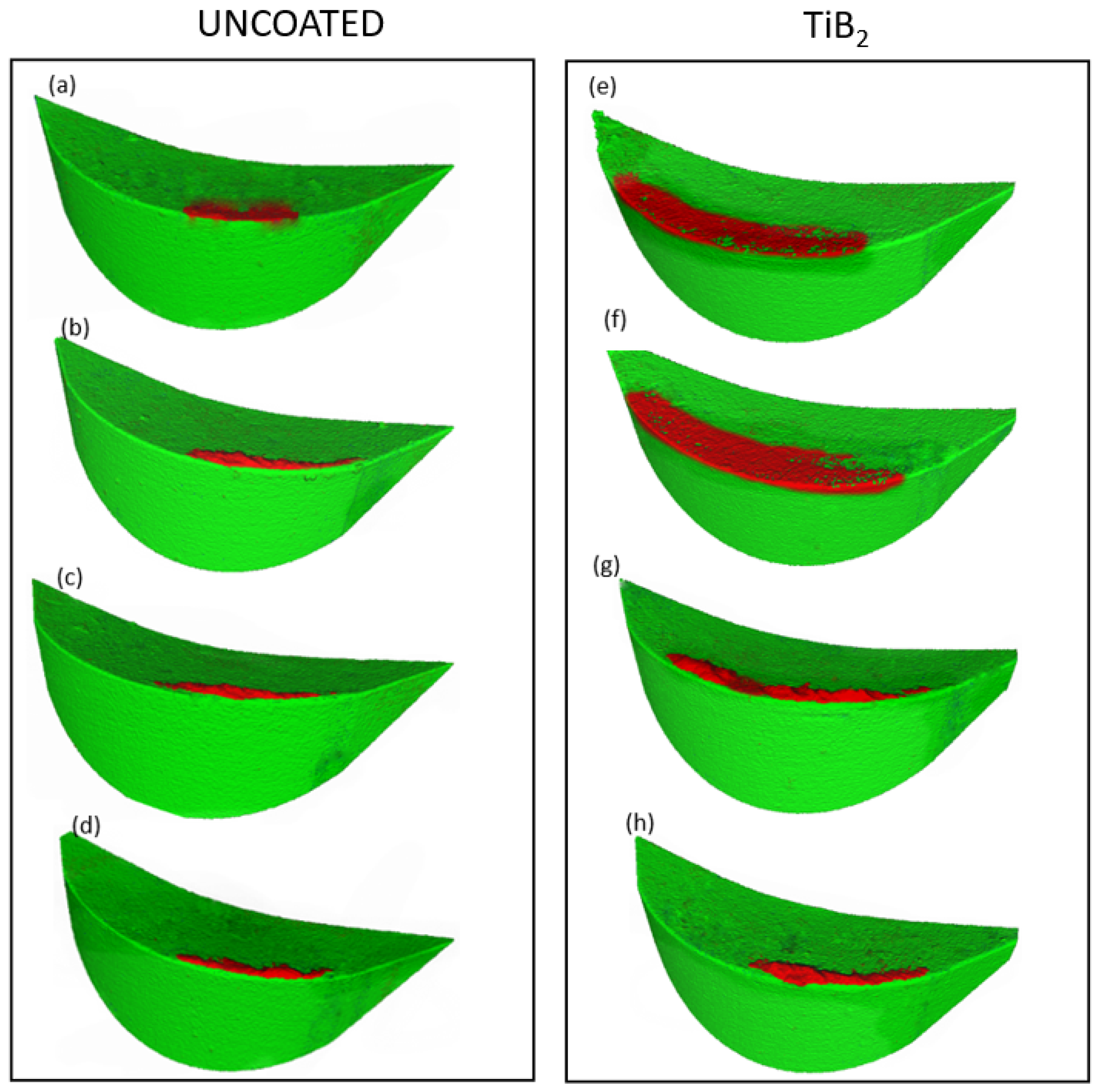
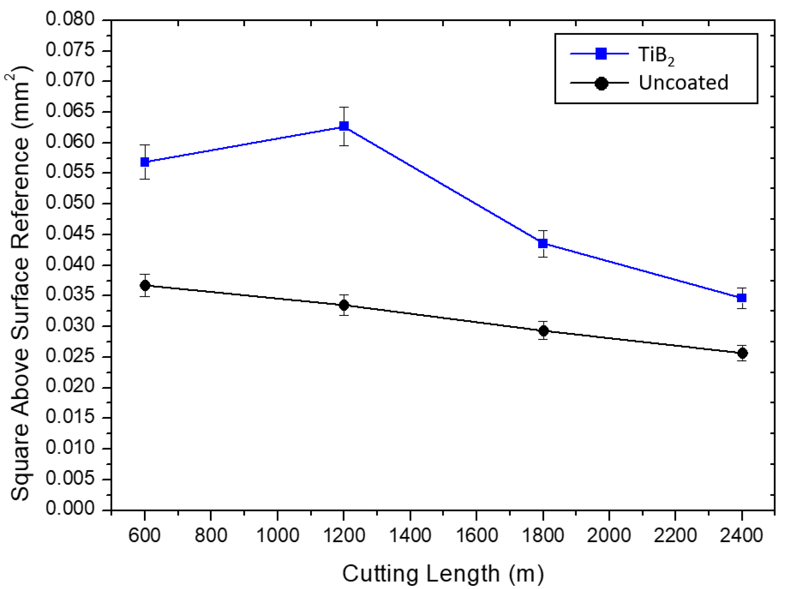
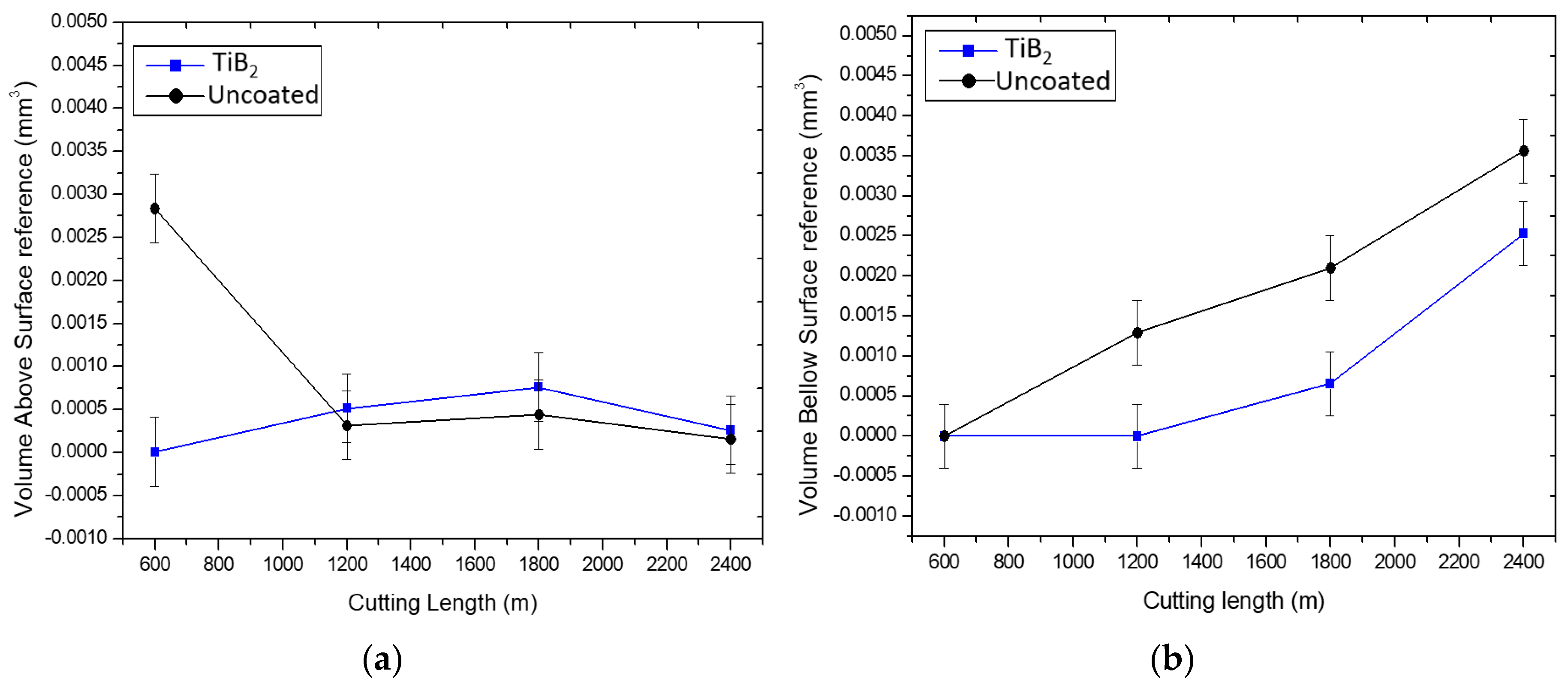
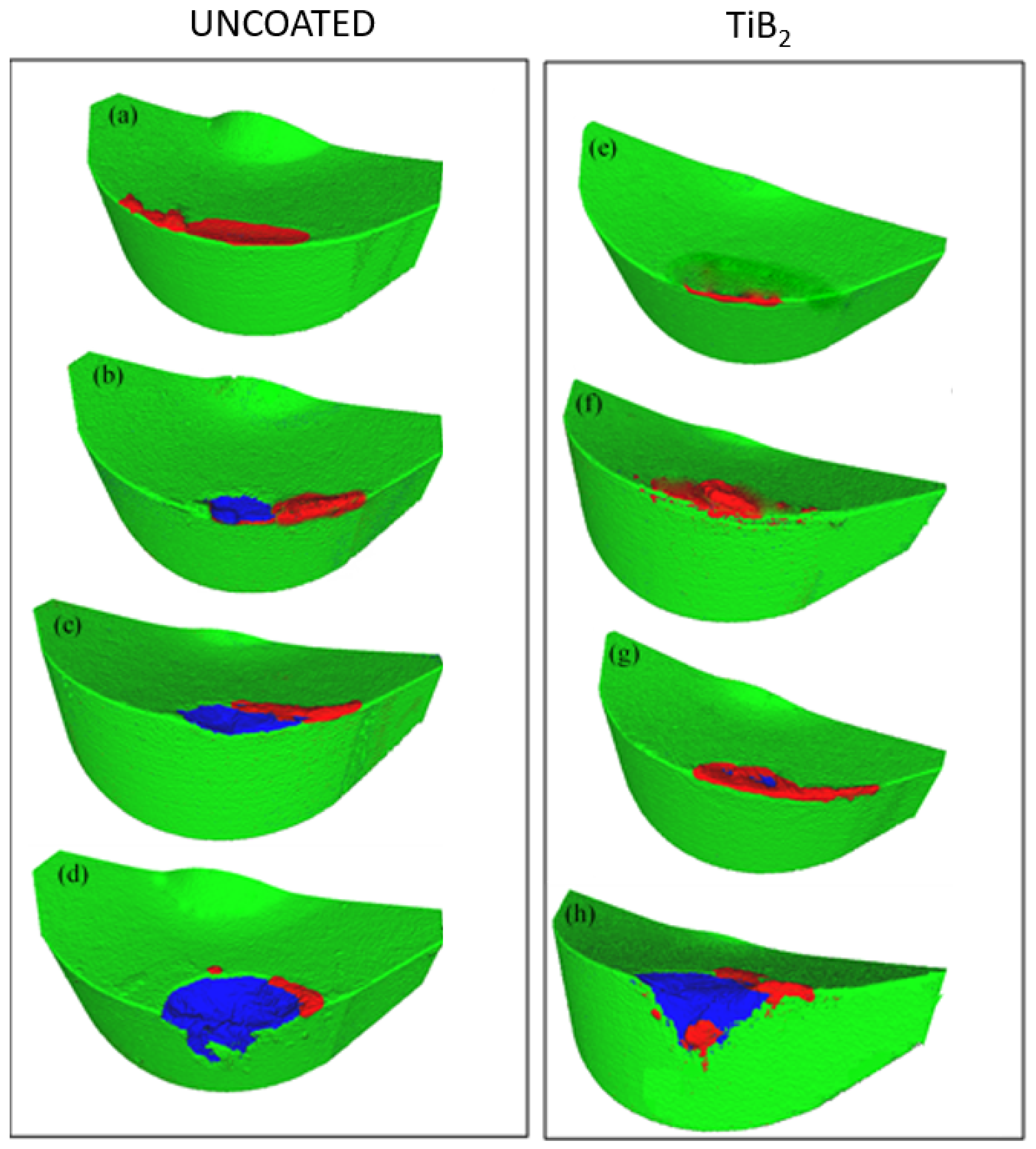
4.1. Wear Performance under Different Machining Conditions

Properties of the TiB2 coating studied are presented in Table 3. We can see in the data that the TiB2 coating has low residual stresses and low hardness. The coating is thus capable of sustaining harsh machining environments during the cutting of TiAl6V4, especially at low speeds (lower cutting temperatures), under conditions of intensive buildup edge formation. However, its efficiency varies under different machining conditions (higher cutting temperatures).

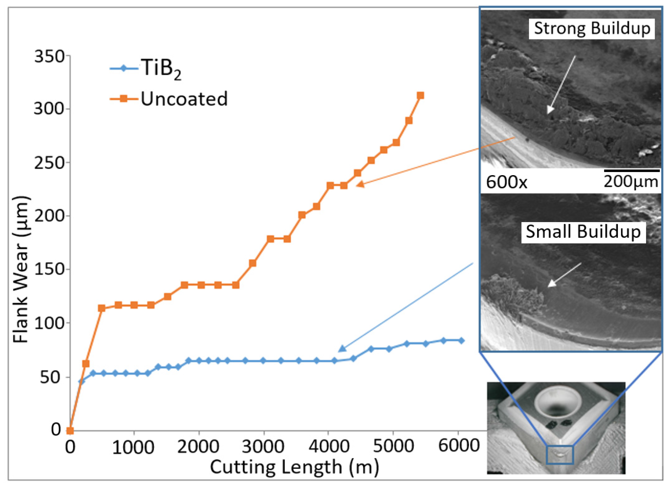
4.2. Rough Turning Operation at Low Speed

Flank wear data is presented in Figure 2. The data indicate that TiB2-coated carbide insert shows significant improvement in the wear rate, as soon as the uncoated insert demonstrates intensive wear rate above 300 microns. SEM images show strong buildup edge formation on the rake surface of the uncoated inset. In contrast, there is very low intensity of buildup edge formation on the surface of the TiB2-coated insert.
Figure 3 demonstrates HR XPS data on the worn rake and flank surfaces of the cutting tool. It shows that complex phenomena are taking place during rough turning, which include:
  • Formation of thermal barrier TiC interlayer at the chip/tool interface [21,23] (Figure 3a);
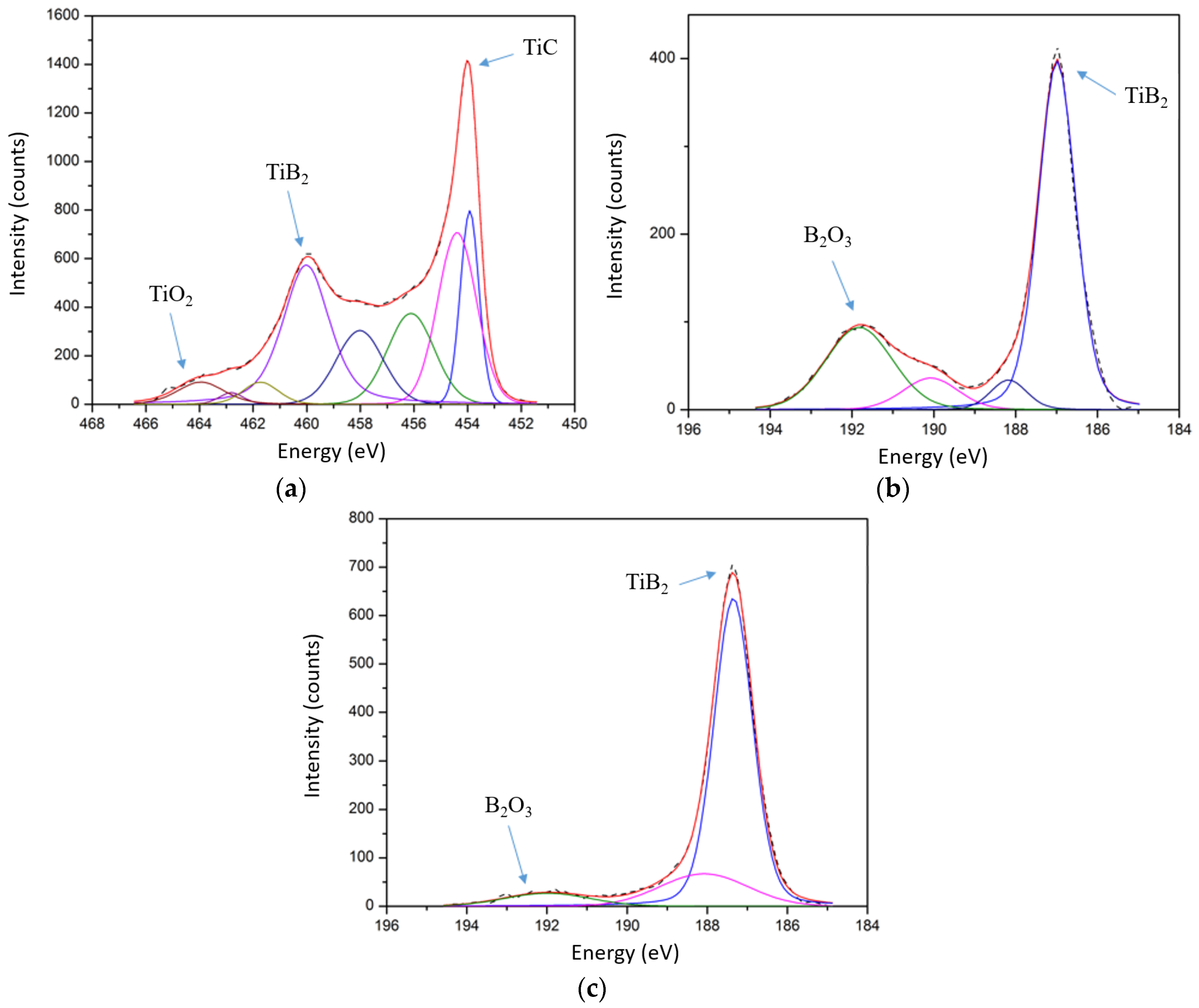
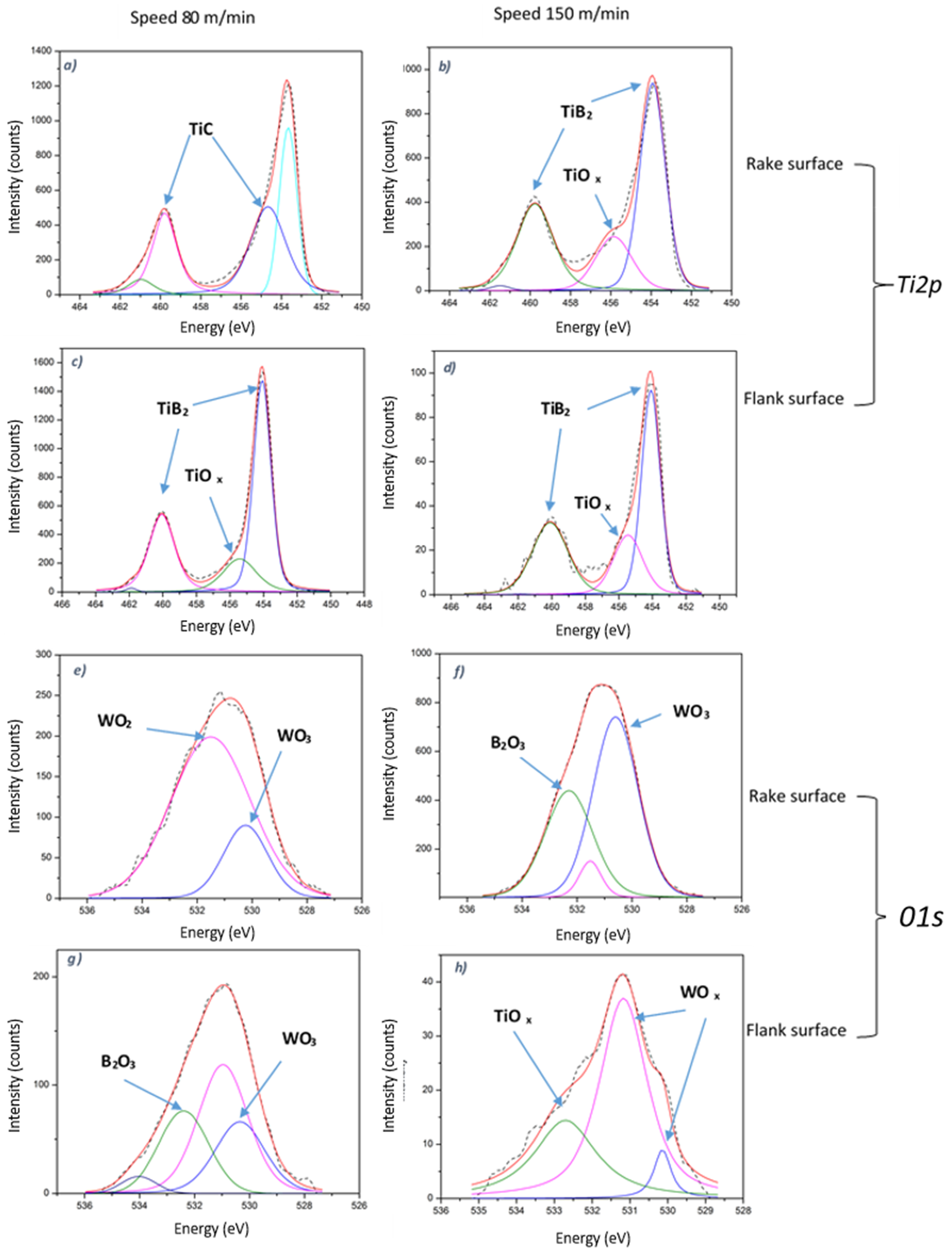
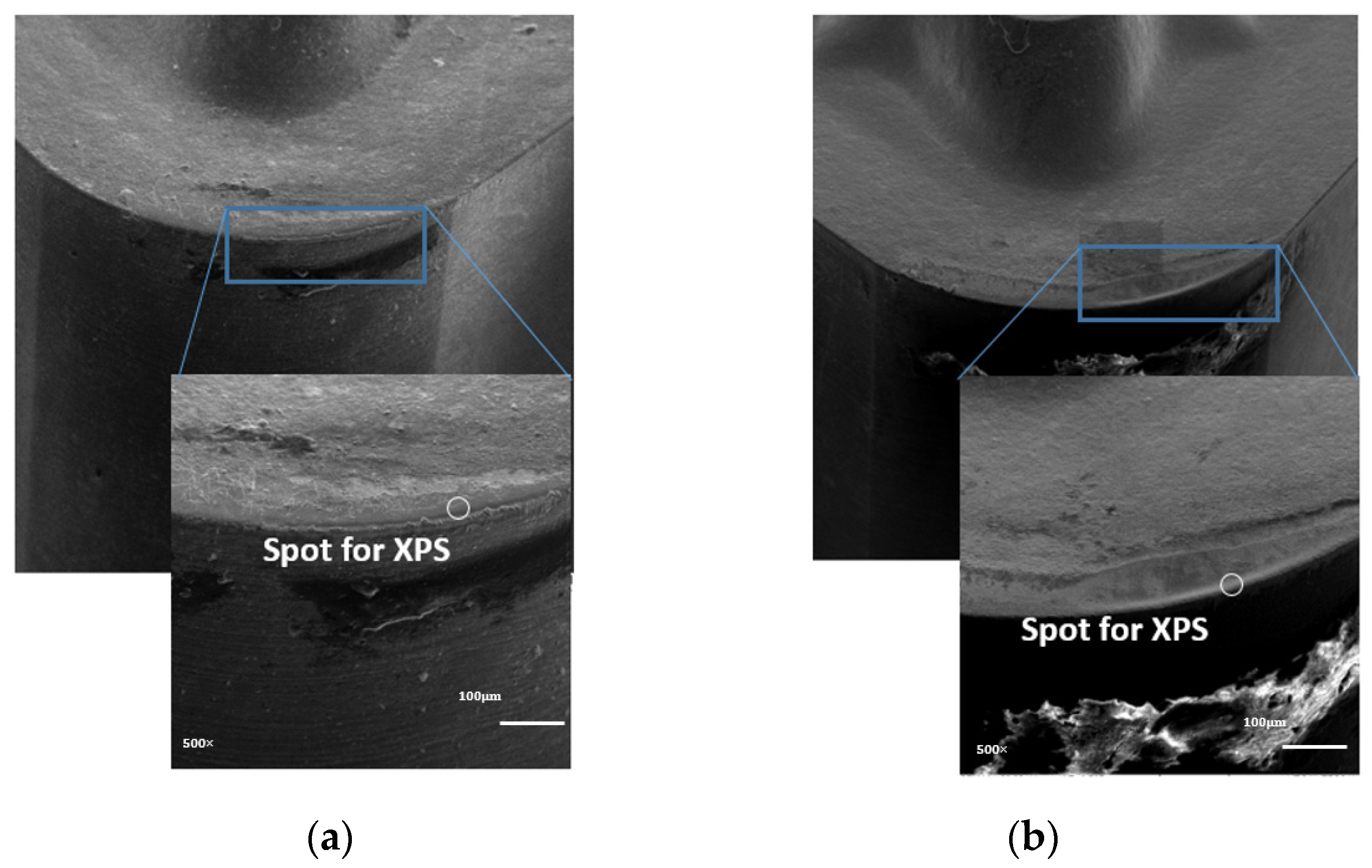
  • Formation of a substantial amount (around 24.9 at.%) of B2O3 lubricating tribo-films, which reduce intensity of buildup edge formation through surface lubrication on the rake surface (Figure 3b);
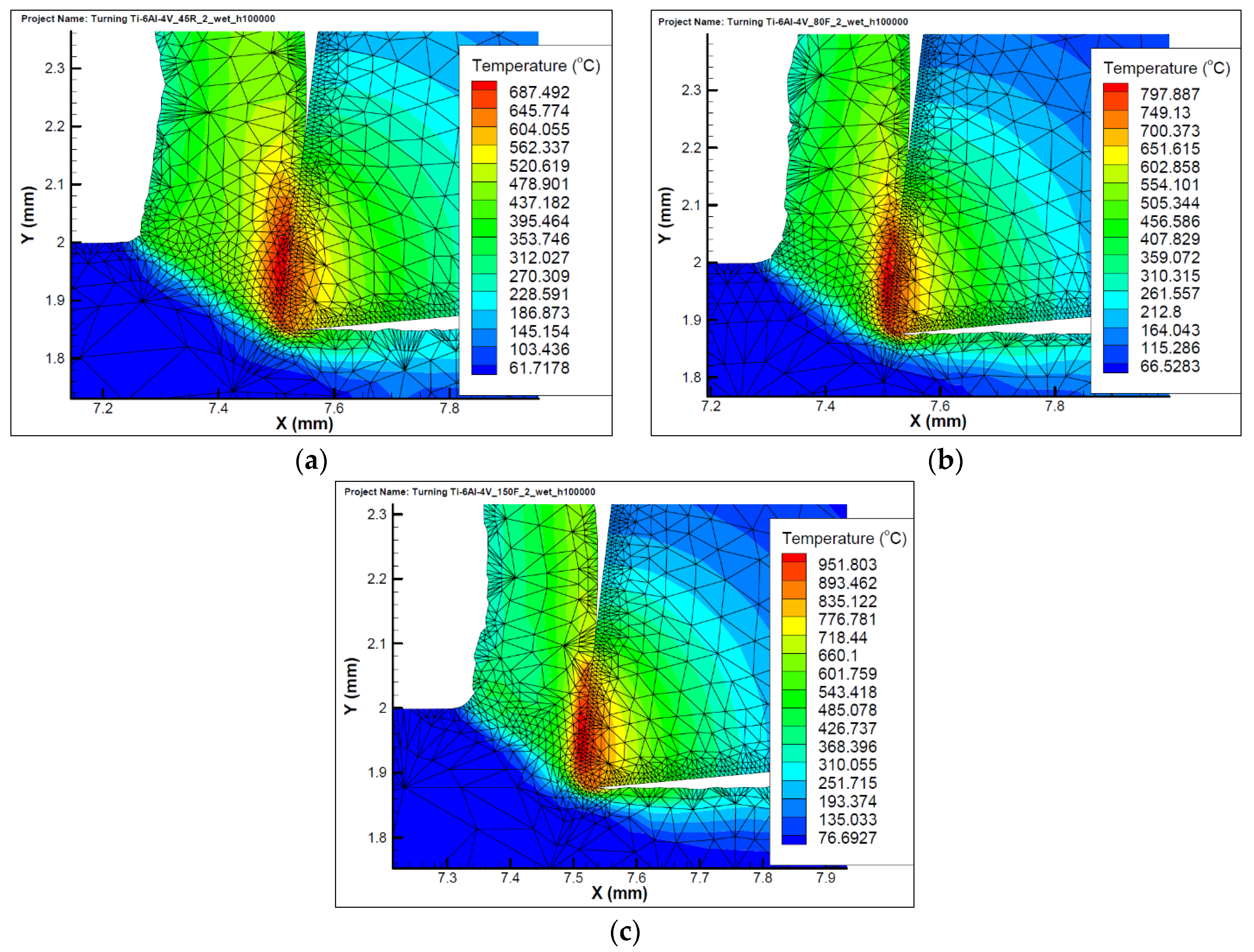
  • Formation of a smaller amount (only 6.5%) of B2O3 lubricating tribo-films due to lower temperatures on the flank surface in correspondence to temperature profile presented in Figure 1a.
Figure 4 exhibits COF vs. temperature data for the uncoated and TiB2-coated inserts. The data presented indicates the formation of B2O3 tribo-films that melt at 450 °C [24] and serve as a liquid lubricant [11]. The temperature during rough turning is relatively low (around 650–700 °C, Figure 1a) and these tribo-films are still fairly efficient [25] (see SEM images in Figure 2).
At higher temperatures, (machining at higher speeds) they do not perform their lubricating role with similar efficiency (see Section 4.3). This behavior was observed and reported by Senda et al. [26] and Munro [27].

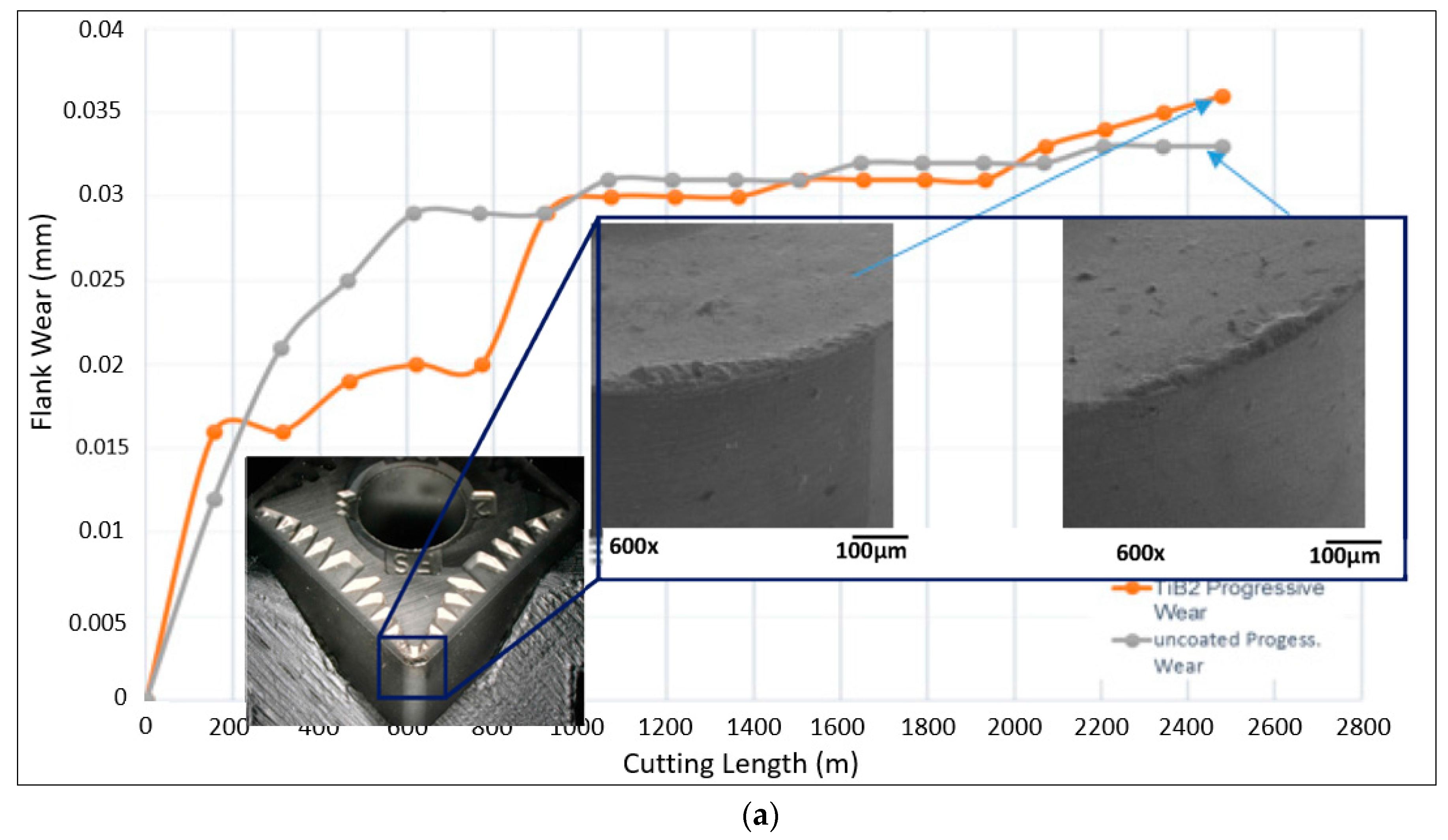
4.3. Finishing Operation

4.3.1. Machining at Lower Speeds: 80 m/min

Flank wear rate data are presented in Figure 5. Tool life is very similar for the coated and uncoated inserts. According to FEM showed in Figure 1b the temperature on the rake surface is around 750–800 °C [28].
3D progressive wear studies were performed by Alicona microscope. 3D images of worn inserts after 600, 1200, 1800, 2400 m length of cut are presented in Figure 6.
Numerical data on the square covered by buildup on the rake tool surface are presented in Figure 7.
The wear volumes data shown in Figure 6 illustrate that very low 3D tools wear as well as build up edge formation intensity (Figure 7) could be identified for the cutting inserts under investigation. Minor differences in the tool wear values were found (Figure 5 and Figure 6). Adhesion of the workpiece material with the buildup edge formation for both uncoated and TiB2-coated cutting inserts were observed. Only very small areas covered by buildups (Figure 6 and Figure 7) could be seen for the cutting inserts coated with TiB2, mostly during the running-in stage. This process is stabilized during the post running-in stage of wear and does not significantly affect the flank wear rate results (Figure 5). SEM studies confirmed that the buildup edge also forms under these conditions (Figure 8a).
XPS analysis was performed at the very cutting edge (see the spots marked at Figure 8). Figure 9 presents XPS data under different speeds in the area of the cutting edge for both rake and flank worn surfaces. As it could be seen from Figure 9a, the formation of the TiC interlayer is taking place [23] on the rake surface at the lower speed of 80 m/min.
In correspondence to the FEM temperature profile on the flank surface, (which indicate lower temperatures, see Figure 1b) only minor tribo-oxidation occurs with formation of only the TiOx phase (Figure 9c). Substantial amounts of lubricating WOx tribo-phases also form on the cutting edge area at a speed of 80 m/min (Figure 9e). This affects the wear performance of the cutting tools. It appears that at temperatures of 750–800 °C on the rake surface, (see Figure 1b) solid lubricating W–O tribo-phases perform as efficiently as liquid B-O tribo-phases. This explains why COF values under these temperatures are quite similar (Figure 4). Formation of both B2O3 and WO3 tribo-phases on the flank surface is shown in Figure 9g, but tribo-oxidation is less intensive compared to the rake surface due to the lower temperatures (see Figure 1).

4.3.2. Machining at Higher Speeds of 150 m/min

3D progressive wear volumes evaluation was performed by Alicona microscope. 3D images of worn inserts after 600 (Figure 10a,e), 1200 (Figure 10b,f), 1800 (Figure 10c,g), 2400 m (Figure 10d,h) length of cut are presented in Figure 10. In this case, the red color represents a material adherent at cutting tool (BUE) while blue color shows damage generated at the cutting tool (crater wear).
Numerical data on the volumetric 3D wear measurement for uncoated and TiB2-coated inserts is presented in Figure 11.
During the initial stage of wear, intensive adhesion of the workpiece material to the rake surface face can be observed (Figure 10a,b,e,f) for both uncoated and TiB2-coated tools. Formation of the unstable buildup structure and its further tearing leads to the chipping on the cutting edge (see Figure 10c,d,g,h, as well as Figure 10b). Moreover, chipping of the cutting edge leads to an increase in the intensity of the buildup edge formation. This is because the buildup edge tearing also removes a part of the cutting edge, which correspondingly may intensify cutting edge chipping.
We also have to keep in mind that at the higher speeds of 150 m/min the mechanism of wear is changing: buildup is quickly worn out (Figure 8b) and therefore the TiC thermal barrier layer does not form [23] (Figure 6b). Higher temperatures under operation (above 900–950 °C, Figure 1c) [28] lead to intensive cratering (Figure 1b and Figure 10b). Therefore, two simultaneously occurring phenomena affect flank wear rate (Figure 5): (a) the buildup edge tearing off and (b) the crater wear. The flank wear intensity of TiB2-coated tool is similar to the uncoated one. Formation of a large amount of lubricating B2O3 and WOx tribo-films (Figure 9f) does not result in high tool life. This is probably due to a higher coefficient of friction of both the TiB2 coating and uncoated tool at elevated temperatures (Figure 4) and dominating crater wear mechanism combined with intensive chipping. On the flank surface we can only see tribo-oxidation of both wearing-off coating layer and the substrate (Figure 9h).
In addition to COF vs. temperature measurements, the tribological performance of the cutting tools at elevated temperatures was evaluated through chip characteristics. This was accomplished via the characterization of chip undersurface morphology using Alicona microscope with simultaneous evaluation of the surface roughness. The studies performed show that there is no substantial difference in chip undersurface morphology (Figure 12): application of both uncoated and TiB2-coated tool results in visible stick-slip phenomenon [11], which is typical for the machining of Ti [28].
This means TiB2 does not improve tribological conditions under higher speeds of 150 m/min and indirectly confirms that B2O3 tribo-films do not affect tribological performance of the tool.

5. Conclusions

The studies performed show that during machining of TiAl6V4 aerospace alloy the efficiency of TiB2 coating application for carbide cutting tools strongly depends on the cutting conditions. FEM data on temperature profile obtained under real wet machining conditions is in strong agreement with tribological performance assessed through COF vs. temperature data as well as chip characteristic data. This allows us to evaluate the efficiency of the tribo-film formation on the friction surface, in particular TiC thermal barrier films as well as B2O3 lubricating films at different temperatures.
The comprehensive 3D wear evaluations combined with XPS and SEM studies of the worn surfaces show that the TiB2 coating is very efficient under rough turning conditions (at low cutting speeds of 45 m/min and high depth of cut of 2 mm) when intensive buildup edge formation is addressed. Based on our analysis, it is proposed that this is due to the formation of a large amount of B2O3 tribo-oxide, which serves as a liquid lubricant. On the contrary, the TiB2 coating shows practically no efficiency at the higher cutting speeds of 80 and 150 m/min under finishing machining operations (DOC 0.125 mm). This indicates that there is no universal solution for various machining conditions when different wear mechanisms are dominating. Therefore, a phenomena-based approach for coating design should be taken into consideration. This is a challenge for future research.

Acknowledgments

The authors acknowledge the financial support from the Natural Sciences and Engineering Research Council of Canada (NSERC) and the Canadian Network for Research and Innovation in Machining Technology (CANRIMT). The authors also acknowledge the MMRI for the use of its facilities.

Author Contributions

Jose Mario Paiva, conceived, designed the experiments, performed Alicona 3D wear measurements, analyzed the data and co-wrote the paper; Mohamed Abdul Manim Shalaby conceived, designed the experiments; Mohammad Chowdhury performed the machining experiments; Lev Shuster and Sergey Chertovskikh, performed the COF experiments; Danielle Covelli Performed XPS experiments; Edinei Locks Junior and Pietro Stolf Performed FEM modeling for machining of TiAl6V4; Amr Elfizy analyzed and discussed the results; Carlos Alberto Schuch Bork performed the SEM experiments on flank wear; German Fox-Rabinovich, analyzed, discussed the results and co-wrote the paper; and Stephen Clarence Veldhuis directed the experiments and analyzed the data.

Conflicts of Interest

The authors declare no conflict of interest.

References

  1. Veiga, C.; Davim, J.P.; Loureiro, A.J.R. Properties and applications of titanium alloys: A brief review. Rev. Adv. Mater. Sci. 2012, 32, 133–148. [Google Scholar]
  2. Guo, Y.B.; Li, W.; Jawahir, I.S. Surface integrity characterization and prediction in machining of hardened and difficult-to-machine alloys: A state-of-art research review and analysis. Mach. Sci. Technol. 2009, 13, 437–470. [Google Scholar] [CrossRef]
  3. Vogli, E.; Tillmann, W.; Selvadurai-Lassl, U.; Fischer, G.; Herper, J. Influence of Ti/TiAlN-multilayer designs on their residual stresses and mechanical properties. Appl. Surf. Sci. 2011, 257, 8550–8557. [Google Scholar] [CrossRef]
  4. Biksa, A.; Yamamoto, K.; Dosbaeva, G.; Veldhuis, S.C.; Fox-Rabinovich, G.S.; Elfizy, A.; Wagg, T.; Shuster, L.S. Wear behavior of adaptive nano-multilayered AlTiN/MexN PVD coatings during machining of aerospace alloys. Tribol. Int. 2010, 43, 1491–1499. [Google Scholar] [CrossRef]
  5. M’Saoubi, R.; Axinte, D.; Soo, S.L.; Nobel, C.; Attia, H.; Kappmeyer, G.; Engin, S.; Sim, W.M. High performance cutting of advanced aerospace alloys and composite materials. CIRP Ann. Manuf. Technol. 2015, 64, 557–580. [Google Scholar] [CrossRef]
  6. Cherukuri, R.; Molain, P. Lathe Turning of Titanium Using Pulsed Laser Deposited, Ultra-Hard Boride Coatings of Carbide Inserts. Mach. Sci. Technol. 2003, 7, 119–135. [Google Scholar] [CrossRef]
  7. Arrazola, P.-J.; Garay, A.; Iriarte, L.-M.; Armendia, M.; Marya, S.; Le Maître, F. Machinability of titanium alloys (Ti6Al4V and Ti555.3). J. Mater. Process. Technol. 2009, 209, 2223–2230. [Google Scholar] [CrossRef]
  8. Ikuta, A.; Shinozaki, K.; Masuda, H.; Yamane, Y.; Kuroki, H.; Fukaya, Y. Consideration of the adhesion mechanism of Ti alloys using a cemented carbide tool during the cutting process. J. Mater. Process. Technol. 2002, 127, 251–255. [Google Scholar] [CrossRef]
  9. Che-Haron, C.H.; Jawaid, A. The effect of machining on surface integrity of titanium alloy Ti–6%Al–4%V. J. Mater. Process. Technol. 2005, 166, 188–192. [Google Scholar] [CrossRef]
  10. Armendia, M.; Garay, A.; Iriarte, L.M.; Arrazola, P.J. Comparison of the machinabilities of Ti6Al4V and TIMETAL® 54M using uncoated WC–Co tools. J. Mater. Process. Technol. 2010, 210, 197–203. [Google Scholar] [CrossRef]
  11. Chowdhury, M.S.I.; Chowdhury, S.; Yamamoto, K.; Beake, B.D.; Bose, B.; Elfizy, A.; Cavelli, D.; Dosbaeva, G.; Aramesh, M.; Fox-Rabinovich, G.S.; et al. Wear behaviour of coated carbide tools during machining of Ti6Al4V aerospace alloy associated with strong built up edge formation. Surf. Coat. Technol. 2017, 313, 319–327. [Google Scholar] [CrossRef]
  12. Pamanik, A.; Littlefair, G. Machining of Titanium Alloy (Ti-6Al-4V)—Theory to application. Mach. Sci. Technol. 2015, 19, 1–49. [Google Scholar] [CrossRef]
  13. Corduan, N.; Himbart, T.; Poulachon, G.; Dessoly, M.; Lambertin, M.; Vigneau, J.; Payoux, B. Wear mechanisms of new tool materials for Ti-6Al-4V high performance machining. CIRP Ann. Manuf. Technol. 2003, 52, 73–76. [Google Scholar] [CrossRef]
  14. Hatt, O.; Crawforth, P.; Jackson, M. On the mechanism of tool crater wear during titanium alloy machining. Wear 2017, 374–375, 15–20. [Google Scholar] [CrossRef]
  15. Zhang, S.; Li, J.; Deng, J.; Li, Y. Investigation on diffusion wear during high-speed machining Ti-6Al-4V alloy with straight tungsten carbide tools. Int. J. Adv. Manuf. Technol. 2009, 44, 17–25. [Google Scholar] [CrossRef]
  16. Shaw, M.C. Metal Cutting Principles, 2nd ed.; Oxford University Press: Oxford, UK, 2005. [Google Scholar]
  17. Melkote, S.N.; Grzesik, W.; Outeiro, J.; Rech, J.; Schulze, V.; Attia, H.; Arrazola, P.J.; M’Saoubi, R.; Saldana, C. Advances in material and friction data for modelling of metal machining. CIRP Ann. Manuf. Technol. 2017, 66, 731–754. [Google Scholar] [CrossRef]
  18. Johnson, G.R.; Cook, W.H. Fracture characteristic of three metals subjected to various strains, strain rate, temperature and pressure. Eng. Fract. Mech. 1984, 21, 31–48. [Google Scholar] [CrossRef]
  19. Lee, W.S.; Lin, C.F. High-temperature deformation behaviour of Ti6Al4V alloy evaluated by high strain-rate compression tests. J. Mater. Process. Technol. 1998, 75, 127–136. [Google Scholar] [CrossRef]
  20. Chen, G.; Ren, C.; Yang, X.; Jin, X.; Guo, T. Finite element simulation of high-speed machining of titanium alloy (Ti-6Al-4V) based on ductile failure model. Int. J. Adv. Manuf. Technol. 2011, 56, 1027–1038. [Google Scholar] [CrossRef]
  21. Fox-Rabinovich, G.S.; Kovalev, A.I.; Shuster, L.S.; Bokiy, Y.; Dosbaeva, G.K.; Wainstein, D.L. Characteristic features of alloying HSS-based deformed compound powdered materials with consideration for tool self-organization at cutting. Wear 1997, 206, 214–220. [Google Scholar] [CrossRef]
  22. ISO 25178-2:2012 Geometrical Product Specifications (GPS)—Surface Texture: Areal—Part 2: Terms, Definitions and Surface Texture Parameters; International Organization for Standardization: Geneva, Switzerland, 2012.
  23. Qi, H.S.; Mills, B. Formation of a transfer layer at the tool-chip-interface during machining. Wear 2000, 245, 136–147. [Google Scholar] [CrossRef]
  24. Aouadi, S.M.; Gao, H.; Martini, A.; Scharf, T.W.; Muratore, C. Lubricious oxide coatings for extreme temperature applications: A review. Surf. Coat. Technol. 2014, 257, 266–277. [Google Scholar] [CrossRef]
  25. Narutaki, N.; Murakoshi, A.; Motonishi, S.; Takeyama, H. Study on Machining of Titanium Alloys. CIRP Ann. Manuf. Technol. 1983, 32, 65–69. [Google Scholar] [CrossRef]
  26. Senda, T.; Yamamoto, Y.; Ochi, Y. Friction and Wear Test of Titanium Boride Ceramics at Elevated Temperatures. J. Ceram. Soc. Jpn. 1993, 101, 461–465. [Google Scholar] [CrossRef]
  27. Munro, R.G. Material Properties of Titanium Diboride. J. Res. Natl. Inst. Stand. Technol. 2000, 105, 709–720. [Google Scholar] [CrossRef] [PubMed]
  28. Hartung, P.D.; Kramer, M.; von Turkovich, B.F. Tool Wear in Titanium Machining. CIRP Ann. 1982, 31, 75–80. [Google Scholar] [CrossRef]
Figure 1. FEM temperature profile at (a) 45, (b) 80, and (c) 150 m/min.
Coatings 07 00187 g001
Figure 2. Flank wear data vs. length of cut for the uncoated and TiB2 coating carbide turning inserts with SEM images of the worn surface (after length of cut of 4000 m).
Coatings 07 00187 g002
Figure 3. HR XPS data on the worn rake (a,b) and flank surfaces (c) after rough turning of TiAl6V4 alloy: (a) Ti2p; (b,c) B1s spectra.
Coatings 07 00187 g003
Figure 4. Coefficient of friction vs. temperature data for the uncoated and TiB2-coated inserts: (1) uncoated; (2) TiB2 coated.
Coatings 07 00187 g004
Figure 5. Flank wear data vs. length of cut for the uncoated and TiB2-coated carbide-turning inserts under finishing operations at the speeds of (a) 80 m/min and (b) 150 m/min.
Coatings 07 00187 g005aCoatings 07 00187 g005b
Figure 6. 3D progressive wear volume data on (ad) uncoated and (eh) TiB2-coated inserts, finish turning at 80 m/min. (a,e) 600 m length of cut; (b,f) 1200 m length of cut; (c,g) 1800 m length of cut; and (d,h) 2400 m length of cut.
Coatings 07 00187 g006
Figure 7. Numerical data on the rake surface square covered by buildup for uncoated and TiB2-coated inserts, finish turning at 80 m/min.
Coatings 07 00187 g007
Figure 8. SEM images of the coated tool worn surface: (a) 80 m/min; (b) 150 m/min.
Coatings 07 00187 g008
Figure 9. HR XPS data on the worn surfaces after finish turning of TiAl6V4 alloy (cutting edge area) at 80 and 150 m/min. Ti2p spectra: (a,b) at 80 and 150 m/min respectively, rake surface; and (c,d) flank surface correspondingly. O1s spectra: (e,f) at 80 and 150 m/min respectively, rake surface; and (g,h) flank surface correspondingly.
Coatings 07 00187 g009
Figure 10. 3D progressive wear volume data on uncoated (ad) and TiB2-coated (eh) inserts, finish turning at 150 m/min. (a,e) 600 m length of cut; (b,f) 1200 m length of cut; (c,g) 1800 m length of cut; (d,h) 2400 m length of cut.
Coatings 07 00187 g010
Figure 11. Numerical data on the volumetric 3D wear measurement for uncoated and TiB2-coated inserts, finish turning at 150 m/min: (a) rake surface square covered by buildup; (b) volumetric 3D wear data.
Coatings 07 00187 g011
Figure 12. Chips undersurface morphology evaluated by Alicona 3D microscope: (a) uncoated; (b) TiB2-coated and (c) surface roughness values (μm).
Coatings 07 00187 g012
Table 1. Workpiece, tool and coolant material properties and cutting contact conditions [18,19,20].
MaterialsPropertyWorkpieceToolCoolant
Density, ρ (kg/m3)443015,700980
Elastic modulus, E (GPa)110705
Poisson’s ratio, ʋ0.330.23
Specific heat, Cρ (J/kg·°C)670178
Thermal conductivity, λ (W/m·°C)6.624.0
Expansion Coefficient, αd W (μm/m/°C)95
Tmelt (°C)1630
Troom (°C)20
ContactHeat transfer Coeff., h (kW/m²·K)10
Heat partition Coeff., α0.5
Friction coefficient, μ0.2
Coolant modeEmulsion—Flood
Coolant Concentration6%
Jet Coolant Radius (mm)5
Friction energy transferred into heat, E100%
Johnson-Cook Constitutive Model Parameters for TiAl6V4 AlloyA (MPa)B (MPa)Cnm
7824980.0280.281
Table 2. Cutting data for the experiments performed.
Machining OperationCutting Tool SubstratesWorkpiece MaterialHardness (HRC)Speed (m/min)Feed (mm/rev)Depth of Cut (mm)
Rough turning, Wet machiningKennametalTiAl6V4 alloy37–38450.152
CNMG432
Grade K 313
turning inserts
Finish turning, Wet machiningKennametal800.12250.25
CNGG432FS1500.12250.25
Grade K 313
turning inserts
Table 3. Properties of the TiB2 coating [11].
CoatingArchitectureProperties
Thickness (μm)Hardness (GPa)Residual Stresses (GPa)
TiB2Monolayer1.7915.5 ± 4.3−0.633 ± 0.0838

