1. Introduction
During the early development of dental implants, and since, many edentulous patients have benefitted from treatments that have increased options for teeth replacement. Treatment using dental implants for partially dentate patients is considered a feasible option, making occlusal reconstruction possible for all types of patients [
1]. Like any other restoration, dental implants also experience mechanical or biological complications [
2]. These complications can be rectified within the implant prosthesis and, therefore, may not end up in failure. Some studies have reported technical complications within implant dentistry that have been the main reason for failures as mentioned above [
2]. Dental implant loss can be categorized as “early” or “late” depending on the extent of the time period taken for that loss after implantation. Late losses of dental implants are considered when the prosthesis has failed after a period of six months [
3].
In order to minimize failures, it is pivotal to understand the risk factors associated with failures and causing clinical complications. The primary predictors are chronic periodontitis, systemic diseases, poor quality of bone, smoking, and advanced age [
4,
5]. An all-important reason for loss of dental implants is mechanical complication. This may be due to mechanical damage to the implant itself, or to the supra-structure and mechanical supports. This leads to implant fractures, and can induce a severe complication of implant extraction with bone from the implanted area [
6]. The defects and the design of an implant are highly unlikely reasons for an immediate or even late fracture. There are load factors, which directly correspond to the direction of occlusal forces applied. These fractures are primarily featured in molar and premolar regions of the mouth. Habits such as bruxism may result in an excessive overload on the implant system, making it one of the most common failures [
7]. Implants with a smaller diameter are more vulnerable to fracture as compared with ones with larger diameters, in the posterior region [
8]; it is important to keep in mind, however, that each dental implant used may have a mechanical history of its own as compared with implants lost as a result of controlled fatigue [
9]. In addition, surface roughening procedures—which are particularly aimed at increasing osseointegration—may also contribute as a damaging factor. Surface changes such as scratches, dents, and craters may infest as additional causes for crack initiation and propagation [
10].
There have been advances reported in implant dentistry, with the success criteria staying scarcely centered on patients. Like any other restoration, there is a probable chance that all will undergo a reduction in strength over a period of time [
11]. Most implants do cross the expected longevity, after 10 years of service [
12]. Hence, characterization of the mechanical problems remains a very important and huge task. The analysis presents an opportunity for diagnosis of the failure and failure pattern, which may be suitable to know for design improvements.
Proper use of analytical techniques is imperative to understanding the clinical performance of medical devices. Despite considerable advancement in ex-vivo techniques, these measures are seldom deployed to characterize chemical composition of the implant surface. Since the structure of bone crystals determines the ultimate strength, it is therefore essential to determine the chemical information of inorganic minerals to fully understand and explain the performance of an implant [
13,
14]. Raman spectroscopy has been used as a potential technique for studying bone quality and surfaces. The technique can provide non-destructive qualitative and quantitative analysis of organic and inorganic constituents of bone via characteristic vibrational frequencies [
15]. It is a suitable technique to obtain information about the nature of calcium phosphate mineral phases, including hydroxyapatite [
16].
Currently, there is minimal evidence on structural alterations and changes in the mechanical properties of implants [
17]. The mechanical complications are common, showing a cumulative incidence of 1.8% in a follow-up done for up to 10 years [
18]. Comprehensive analyses of retrieved dental implants are rare in biomechanical and dental literature, as incidences of fractures and failures are considered low. Scanning electron microscopy revealed intra-oral fractures and fatigue striations in dental implants [
19]. However, studies did not show any failure analysis of retrieved implants under lab conditions which can provide some information on the operating mechanisms of dental implants. Most of the literature available does not comment on stress against the number of cycles to failure analysis [
20]. Hence, the aim of this study was to examine the surface of failed dental implants that were removed due to any biological reason. The hypothesis was that retrieved or failed dental implants have surface and mechanical property alterations after use. In addition, the surface properties of retrieved dental implants were analyzed by Raman spectroscopy to determine bone (apatite) formation around the implant surface. The metal composition of the implants was also checked. The analysis was also performed in SEM-EDX (energy dispersive X-ray spectroscopy in the scanning electron microscope). This identification is semi-quantitative, but allows the establishment of a clear distinction between the implants. The above studies illustrate the partial information on the retrieved dental implants. One can predict that there may be increased incidence of mechanical failures and complications with the passage of time. Therefore, exemplar testing was also performed complimented with nanoindentation testing to predict structural alterations and changes in mechanical properties after failure.
2. Materials and Methods
2.1. Implant Specimens
Thirty-eight dental implants were retrieved from 43 patients (mean age [±SD] considered was 50 ± 13.2 years) who underwent implant surgery (in Saudi hospital/OPD, Riyadh, Saudi Arabia) during a period of 6 years. The patients’ informed consent was obtained under a protocol approved by the Institutional and Ethical Review Board of King Saud University (FR-2017-46), explaining to them the use of the retrieved implants for scientific research. All efforts were made to protect the complete anonymity of the patient. The implants were collected from the upper and lower jaw, with failure most likely due to lack of bone support (suggested by operators). In addition, the retrieved implants were investigated for solely technical reasons, without addressing any medical issues. Although the patients’ medical background information was known, the information was not really considered. All implants that have failed within 6 years of their placement (2010–2016) were included. The study population included 23 males and 20 females. Failures were detected by measuring peri-implant radiographic examination, bleeding on probing, suppuration, and mobility. As soon as the implants were retrieved, specimens were stored in brand-new sterile plastic bottles. This procedure was monitored and carefully handled to avoid excessive and subsequent contamination. Dental implants studied were of a cylindrical design, with an implant diameter of 3.6 mm and lengths of 8 to 10 mm. These measurements were not part of the inclusion criteria. Previously, implant placements were carried out according to the following indications: single-tooth, partial edentulism (two or more implants), and complete edentulism under local anesthesia using the Swedish protocol [
21]. Twenty Straumann dental implants (Institute Straumann, Waldenburg, Switzerland) were retrieved after 6 years, while one was immediately retrieved after increased mobility (less than 6 years implant failure). Seventeen other dental implants were also retrieved (TiUnite
®, Nobel Biocare, Goteborg, Sweden) and analyzed by the same protocol described previously.
Surface Cleaning of Dental Implants
The cleaning protocol for all retrieved implants and implant parts involved the use of chemical solutions for the removal of blood/soft tissue along with organic layers. The retrieved specimens were inserted into 100 mL glass beakers filled with different chemical solutions for removal of debris. The specimens were completely inserted inside. Three percent sodium hypochlorite solution was used for the removal of blood/soft tissue in < 10 min. Pure acetone (CAS 67-41-1; Sigma Aldrich, St. Louis, MI, USA) was used for 30 min to remove organic layers. There was no effort to remove the inorganic layer; this was to carry out the analysis of hydroxyapatite bone crystals. While the specimens were inside the solution, the beaker was kept on a hot water ultrasonic bath. Specimens were thoroughly rinsed with water or ethyl alcohol between placement in different solutions.
2.2. Backscattering Scanning Electron Microscopy Analysis of Failed Implant Surfaces
Retrieved failed dental implants (n = 9 for each group; ST & TiUn) and control specimens were visualized using SEM in a back-scattering mode. Samples were rinsed with PBS and post-fixed for 1 h using (1%) osmium tetraoxide. After rinsing with PBS again, the specimens were subjected twice to dehydration in an ascending series of ethanol solutions (75%, 85%, 95%, and 100%, 60 min each). Specimens were then mounted with conductive tape on aluminum stubs (double-sided carbon tape) in such a way that they could be observed in a cross-sectional view and later stored in a desiccator for 24 h. They were sputter coated with a 30 nm thick (pre-set) layer of gold palladium alloy for 120 s and viewed at different magnifications using SEM (Hitachi S-3400N, Hitachi High Technologies America, Inc., Schaumburg, IL, USA) operated at an accelerating voltage of 10 kV. The images viewed on the monitor were evaluated by two examiners. The implants were specifically examined for early signs of mechanical failure (cracks) through a surface scanning of the entire periphery of the implant surface (360°). While examining, a few considerations, like identification of any surface treatment and location of defects, were taken into account. The dental implant samples (two implants each for both systems) were also analyzed by EDS (Joel, JSM-6380A Analytical Scanning Electron Microscope with EDS elemental analyzer, Tokyo, Japan) to verify the compositions of the materials by taking an electron beam voltage of 15 kV and a beam current less than 3 × 10⁻⁷.
2.3. Raman Spectroscopy Measurements
Raman spectroscopy was used to analyze the chemical composition and crystallinity of bone crystals present on failed dental implant surfaces (ST & TiUn). With this spectroscopic approach, the molecular properties of the newly formed bone around the failed implant (n = 4 for each group; ST & TiUn) could be evaluated. Micro-Raman measurements were performed using a Jasco NRS-2000C instrument (Jasco Inc., Easton, MD, USA). The spectrometer was connected to a microscope with 100× magnification and a 160 K frozen CD detector (Spec-10: 100B, Roper Scientific Inc., Trenton, NJ, USA). Spectral recording was done in a back-scattering mode (1 cm−1 spectral resolution) using a 100× objective lens, with an argon ion 514.5 nm laser at 785 nm wavelength (spectral resolution of 1.6 cm−1), and power < 500 μW with a superior signal/noise ratio having a laser driver power of about 5 mW. This was essential to allow a focus of 1 μm diameter within the sampling area. The spectrometer was set to operate in a confocal mode, with a slit opening of 11 μm, and a grating of 1200 mm−1. In the confocal mode, a spatial resolution of a 1–2 μm within the x–y plane was achieved. The spectra were recorded covering a total frequency range of 400–1800 cm−1. Characteristic Raman signatures were then selected as peaks, limited by a linear background. In order to obtain a descent representation of the specimens, six frames of 30 s exposure were recorded and later subjected to system background removal, spectral analysis, and dark count correction. The intensities were completely normalized for final analysis. All spectra were recalibrated to the amplitude of the respective spectra. These spectra were presumed to have contributed from the implant surface normalized around the 960 cm−1 region. No sample degradation is expected upon laser irradiation as Raman spectroscopy causes minimal changes on the specimens.
2.4. Fatigue Testing
The cyclic mechanical testing was carried out using a Minneapolis servo-hydraulic system (MTS, Minneapolis, MN, USA, with a 250 kN load capacity [
22]. The machine was driven under load control. In order to fix the testing implants on the machine, a custom-designed steel cage holding was machined containing a slotted steel cylinder. The implants were tested (
n = 3 for each group having same batch number with bone residues on the surface; ST & TiUn) under dry conditions and kept inside the steel cylinder up to the second thread around the head of the implant. The specimen holder was then inserted inside the holding stage at an angle of 30°, fixing it to the testing machine. This positioning converted the testing force into a bending moment applied to the implant abutment, according to the static bend strength of the retrieved implant specimens (ISO 14801 recommendation/standard for dynamic fatigue testing for dental implants) [
23]. At a displacement rate of 0.4 mm/min, quasi-static bending strength (a vertical load) was applied until the retrieved implant underwent a permanent plastic deformation or fracture, followed by a load drop. The machine was stopped when 5 × 10
6 cycles had acceded without apparent failure. The machine automatically stopped after fracture and recorded sinusoidal loads with minimum to maximum loading ratio of
R = 0.1, with test frequencies in the range of 2–15 Hz (ISO 14801 recommendations). All cyclic loads for each retrieved implant were scaled or normalized to their quasi-static test strength in the range of 0–1. The specimens were rigidly clamped at the base, which appeared more severe as compared with in vivo flexible conditions experienced by a dental implant. However, these rigid clamping conditions did not seem to affect conclusions drawn from the results. The testing was performed under ambient room temperatures.
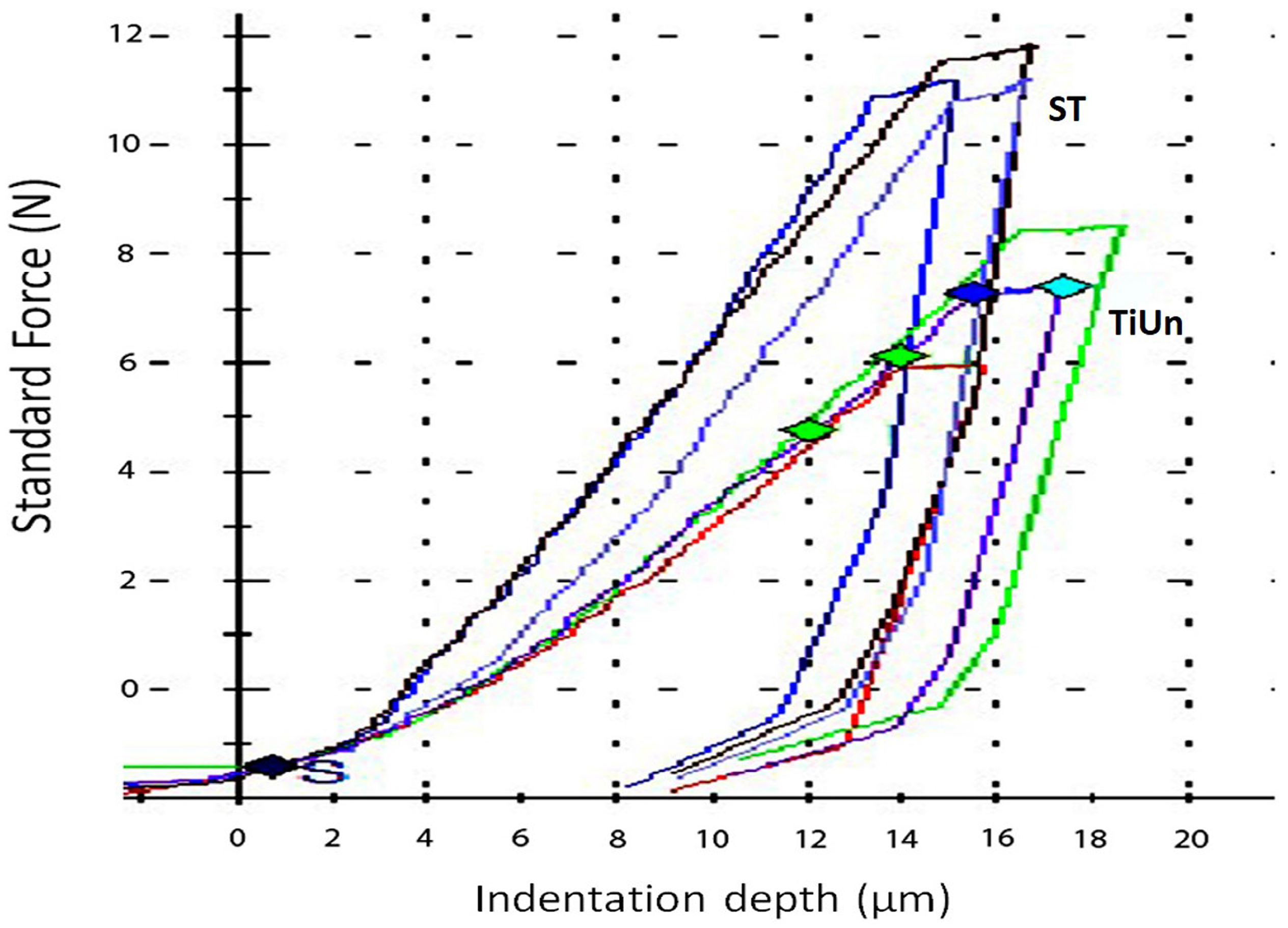
2.5. Instrumented Indentation Testing
Three specimens from each retrieved implant group (n = 3) were embedded in an epoxy resin (Epofix, Hatfield, PA, USA) along a longitudinal axis and were cut in the middle with a Struers diamond cut-off wheel (Struers, Denmark), ground with 2000 grit SiC papers, and polished with diamond pastes (DP, Struers) up to 1 μm in a grinding polishing machine (Buehler Minimet 1000 Polisher/Grinder, Lake Bluff, IL, USA). After cleaning the specimens inside an ultrasonic bath, the elastic index (ƞIT; elastic to total work ratio) and indentation modulus (EIT) were determined using a (instrumentation indentation) universal hardness testing machine (Zwick Roell, Ulm, Germany). Five indentation force depth curves were recorded for each specimen using a Vicker’s indenter (CSM Instruments, Peseux, Switzerland) with a 9.8 N load for 10 sec contact time. The average values for mechanical testings were recorded to characterize the retrieved dental implant specimens.
2.6. Statistical Analysis
All mechanical properties were statistically compared by an unpaired t test at a 95% confidence interval. All data were checked for normality using Shapiro–Wilk tests. The correlation between the observed defects was evaluated using Chi-square tests with the significance level set to p = 0.05.
4. Discussion
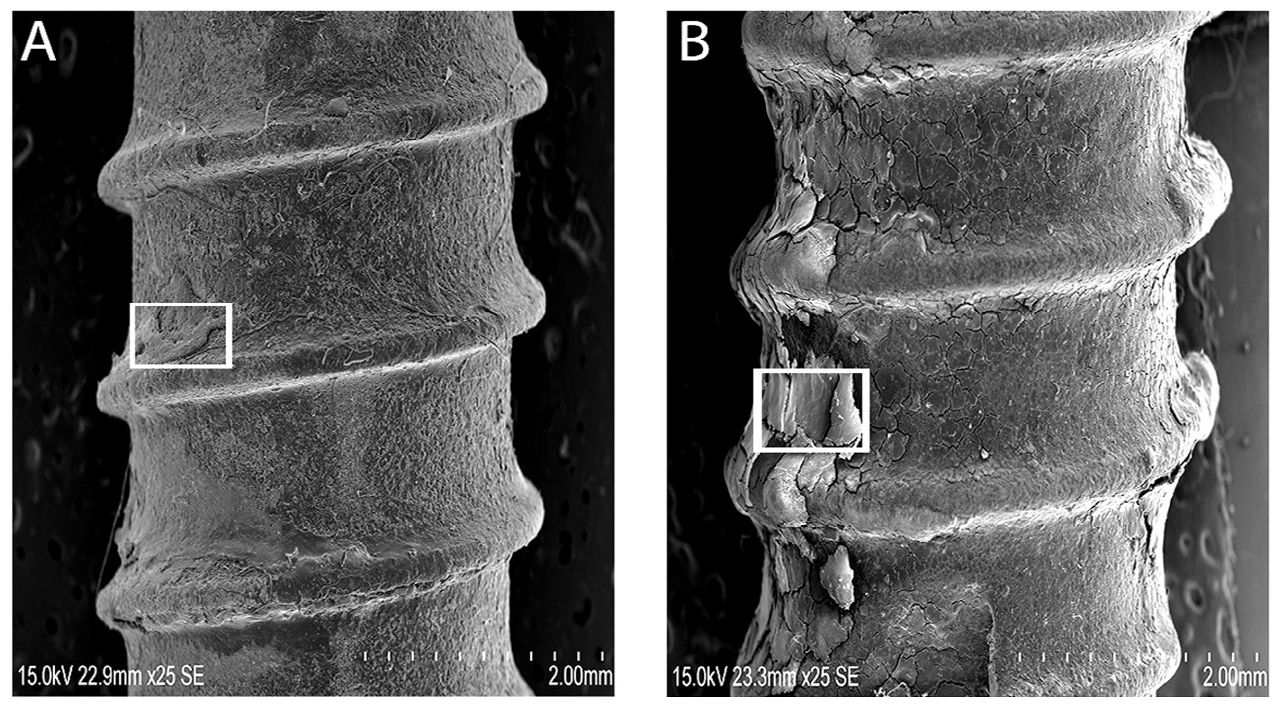
Despite the fact that the implants showed bone residues covering the implant surface, the dental implants may have failed due to progressive reduction of bone support or biological support. Yet, the qualitative analysis of bone on retrieved dental implants necessitated consideration of surface analysis for any mechanical crack formations. The retrieved implants were considered as “in-vivo” undergoing repeated loading inside the oral cavity, presenting enough evidence of oral stresses and its environment on mechanical integrity. Clinically failed dental implants were encapsulated with soft tissues, but showed areas of bone (
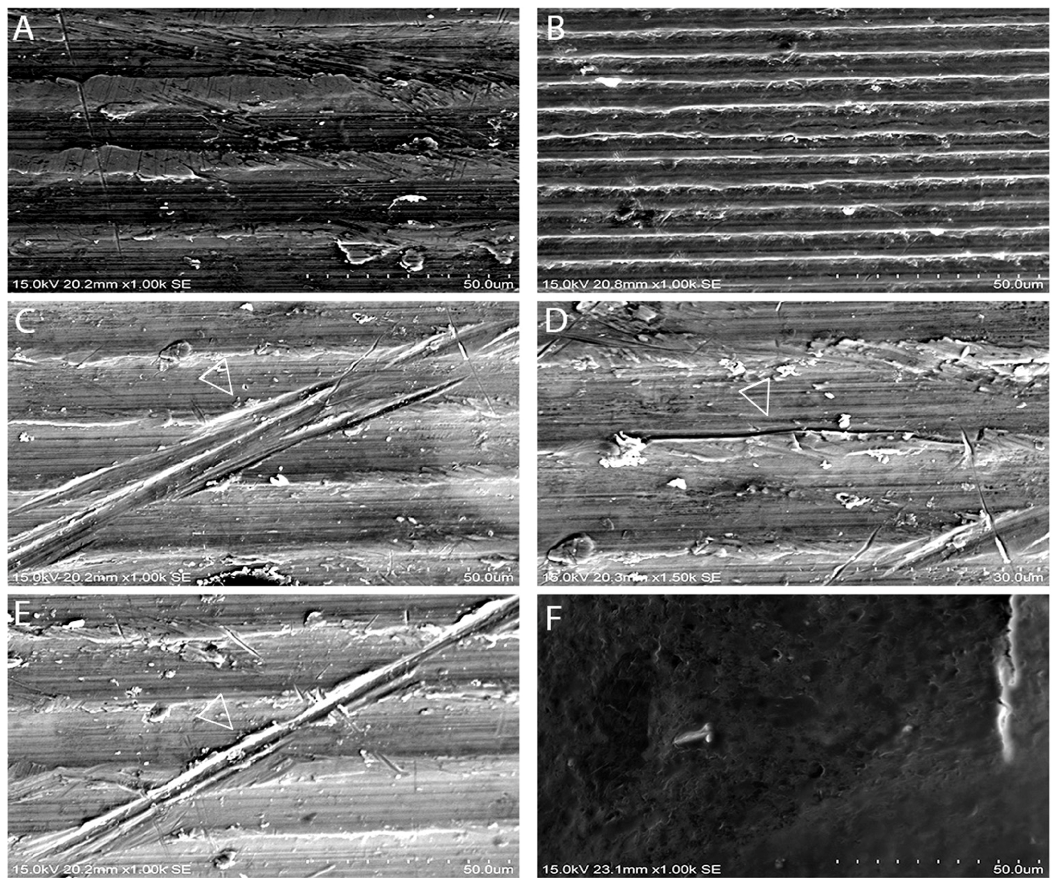
Figure 2A,B). In addition, there were alterations in the mineral composition and accumulation of organic material with retained oral integuments and bone-like formations inside ST implants (
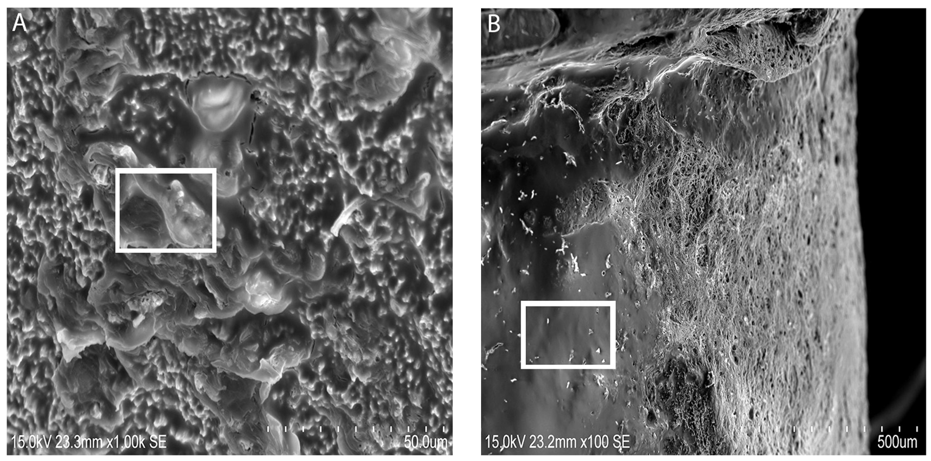
Figure 2C). The elemental composition of retrieved ST implants with bone-like formations was dominated with Ca and Na. Both groups of implants revealed a bone-like covering (
Figure 3A,B) with distinct gaps between the implant and bone. This may be due to the complex interaction of the implant surface with the biological environment into which it was inserted. Hydroxyapatite dissolution and reprecipitation can occur along the bone implant interface [
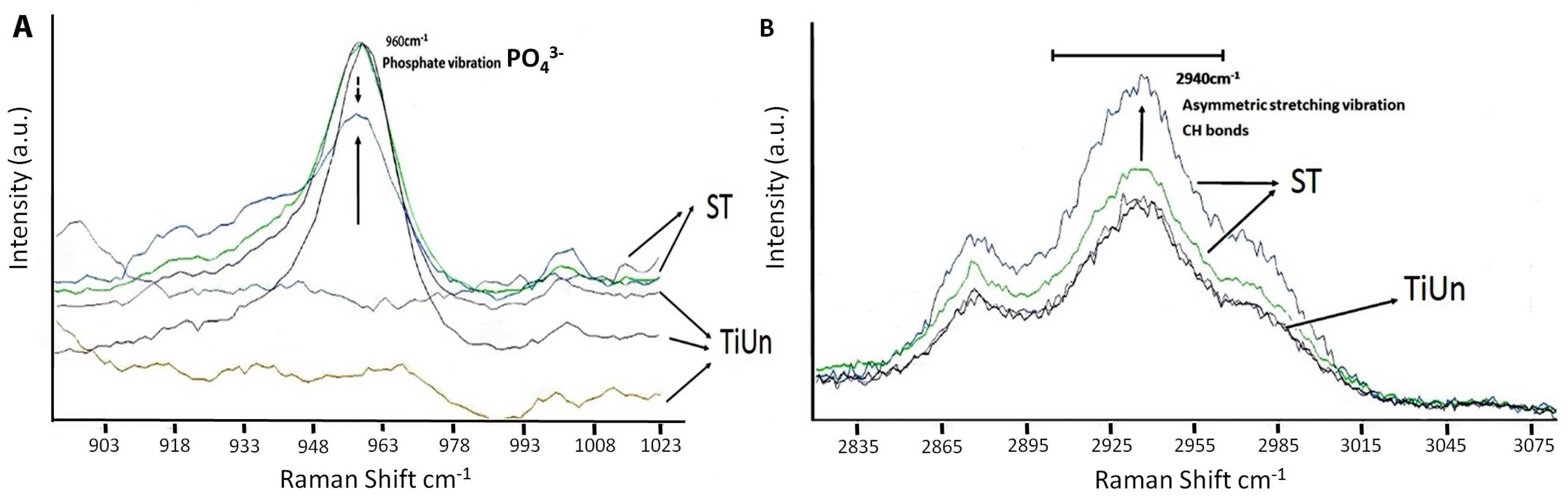
25]. The presence of a phosphate peak at 960 cm
−1 within the Raman spectrum supports the possibilities (
Figure 4) related to the presence of bone formation. The SEM images showed deposition on the surface of ST implants, which the authors speculated as hydroxyapatite crystals (
Figure 3A,B). This is in conjunction to the presence of a hydroxyapatite peak found in the Raman spectroscopy result. By comparing the SEM images (
Figure 3A,B), one can observe the aspect of the new bone surface which seems more dense in ST implant groups (
Figure 3A) as compared with TiUn (
Figure 3B). The TiUn groups were associated with crack-like defects or full cracks with a statistical difference. The results (
Table 1) indicate the proportion of defects found in both implant groups, further strengthening the fact that the TiUn implant groups had more reasons to fail. The surface of TiUn implants showed cracks in the vicinity of main cracks but showed no indication of a final fracture within the implant. Therefore, the hypothesis that retrieved or failed dental implants have surface property alterations can be partially rejected.
Surface characterizations of retrieved or failed dental implants have gained a lot of interest in the last years as a tool to interpret failure mechanisms [
26]. In an effort to eradicate variability in results due to placement of different dental implants amongst patients, only two types of implants were included in this study. This study was based on a random selection of implants of two different companies having undergone different surface preparation and lengths. Therefore, the samples collected are considered as representatives of the types of implants used in clinical implant dentistry. This failure analysis is reflective of the causes and means to understand and prevent failure reoccurrence by improving the dental implant’s biological and mechanical performance inside the oral cavity [
27]. The exposure of dental implants to any liquid medium mimicking oral environmental conditions was avoided and tests were performed in dry-air laboratory conditions, as received.
Raman spectroscopy enabled qualitative analysis at a molecular level, where it can predict the presence of bone and its maturity. It is an optical tool for less invasive and less destructive analysis of biological samples, giving precise information on biochemical composition [
28]. Many have accepted Raman spectroscopy as a viable tool for study of bone mineralization and analysis. The Raman spectra interfered with the fluorescence of biological specimens and hence is preferred over infra-red spectroscopy [
29]. By chemical mapping and monitoring peak intensities at 960 cm
−1 (
) and 2940 cm
−1 (CH bonds), it was possible to distinguish which implant type had bone growth around its surface. In the present study, the increased organic and inorganic peaks (
Figure 4A,B) showed an osseo-integration somehow taking place. The increase in the quality and sharpness of Raman peaks at 960 cm
−1 (chemical signature for bone) amongst ST implants was due to slightly more bone deposition on the implant surface, known as hydroxyapatite coverage. It is important to note that, despite being not statistically significant, the results of 960 cm
−1 amongst the ST implants at the surface of the inserted sites showed the same level of bone deposition in all specimens. We found a difference in Raman spectroscopic intensities between the two groups as the ST groups showed higher peak intensities than the TiUnite groups (
Figure 4A,B). The organic peaks at 2940 cm
−1 related to the CH bonds were found, showing the influence of collagen deposition (
Figure 4B). The organic bone matrices are primarily made up of type I collagen [
30,
31], synthesized by osteoblasts, that is mineralized with hydroxyapatite during the later stages of osteogenesis [
32]. Therefore, the higher deposition seen amongst the ST groups indicated a higher mineralization. In the present study, this correlation was found between the organic (2940 cm
−1) and inorganic contents (960 cm
−1), in particular within the ST groups. The ST implant surface was almost completely covered with the layer of bone minerals, with the exception of one peak in the TiUn group that showed higher crystallinity comparable to the ST group. The crystallinity of the formed bone is known to influence the clinical performance of the bone implant. The crystalline bone is less susceptible to dissolution leading to rapid supersaturation phosphate and calcium ions in the implant environment [
33]. When hydroxyapatite is low in crystallinity, this will elevate the local pH, resulting in a lesser cell proliferation and a lesser bone volume [
34]. Therefore, the hypothesis that retrieved or failed dental implants have surface property alterations can be partially rejected.
In order to understand the failure analysis, the study partly comprised fatigue testing to identify the fatigue fracture mechanism amongst the two groups. The results (
Table 2) indicate that the oral environment may have caused the significant reduction in the TiUn group. The authors speculate that the oral environment may have been a significant factor in the overall failure of the implants. The study did not identify or analyze corrosion mechanisms as this point was not elucidated in the project. This should be pivotal in future studies to analyze the fatigue or failure of dental implants. A typical biting force in an adult is close to 38.8 N to 661.5 N in upper first molars [
35].
Indentation techniques have been widely used for assessing bone tissue micromechanical properties [
36,
37]. Based on the results of this study, the null hypothesis was accepted, as retrieved implants demonstrate morphological alterations but no statistical differences. The indentation modulus (
EIT) at the surface-to-core cross sections of both the implant systems is less than half that of titanium (103 GPa) [
38]. It can be speculated that there could have been damage during implant insertion due to high profile of the bone. The presence of bone around the implant can be inferred by the elastic modulus measured by the indentation. The unexpectedly low Young’s modulus of the surface maybe also be due to testing of the bone on the implant surface rather than the alloy. There were no statistical differences between the two groups as far as the elastic index was concerned.
Special considerations were taken not to remove any inorganic layers on the retrieved dental implants by the use of sodium hypochlorite solution at a concentration of 3%. After cleaning with the solution, thorough rinsing of the implants was performed using water or ethyl alcohol to make sure there was no contamination left behind. Future studies are required to analyze any contamination due to the cleaning protocol and comparison studies for surface defects before implantation.


 ,
, 


