
Wear Transition of CrN Coated M50 Steel under High Temperature and Heavy Load


1
Research Lab of Space & Aerospace Tribology, Harbin Institute of Technology, Harbin 150001, China
2
School of Material Science and Technology, Harbin Institute of Technology, Harbin 150001, China
*
Author to whom correspondence should be addressed.
Coatings 2017, 7(11), 202; https://doi.org/10.3390/coatings7110202
Submission received: 22 September 2017
/
Revised: 3 November 2017
/
Accepted: 15 November 2017
/
Published: 20 November 2017
(This article belongs to the Special Issue Coatings for Harsh Environments)
Abstract
:The combination of high temperature indentation and wear test provides a useful way to investigate wear of CrN coating and wear transition mechanisms. In this paper, the high temperature hardness of CrN coatings and load bearing capacity, Lb, of CrN coated M50 disks were determined from spherical indentation at temperatures up to 500 °C. Wear tests with different normal loads were carried out at the same temperatures as the indentation tests. The results show that wear mechanism of CrN coating changes with external load, P, and temperature, T. Under a tested condition of P < Lb and T < 315 °C, abrasive is the dominant wear mechanism for CrN coating. Under a tested condition of P < Lb and T ≥ 315 °C, wear of CrN coating transitions into mild oxidation wear due to the lubricating effect of chromium oxide film. Under a tested condition of P > Lb and T < 315 °C, wear of CrN coating was controlled by coating fracture. Under a tested condition of P > Lb and T ≥ 315 °C, wear of CrN coating transitions into the severe wear mode, due to the tensile fracture of oxidation films, thereby leading to adhesion between CrN coating and tribo-counterpart. The presented method can be helpful in predicting permissible load and working temperature in tribological applications of CrN coating.
1. Introduction
Chromium nitride (CrN) films, with good oxidation, anti-corrosive and anti-adhesive properties [1,2,3,4], are promising candidates for protection in high temperature applications, such as for tools or aerospace rolling bearings. Nevertheless, the wear of such CrN coating–steel substrate systems at elevated temperatures is still not completely understood [5,6,7,8]. This is because the material removal process for CrN coatings is dependent on operation parameters (load, temperature, etc.). Wear mechanism for CrN coatings may be changed when the external load or working temperature are changed. Lim and Ashby [9] first suggested using the terms “wear transition” for describing the changing of dominant wear mechanisms with contact pressure and velocity in a steel tribo-pair. Later, Wang et al. [10] studied the wear transition for homogenous brittle materials, such as Al2O3, Si3N4 and SiC ceramics. There is still a lack of information about the wear transition of CrN coatings. Therefore, the aim of this paper is to evaluate dependency of the wear of CrN coatings on both temperature and external load.
The wear transition from abrasive wear to oxidative wear was frequently observed for CrN coatings at high temperature. Polcar et al. [11] performed elevated temperature ball-on-disc tests on CrN coatings sliding against Al2O3 ball. It was found that the tribological properties of CrN coatings at high temperature were predominantly influenced by formation of a chromium oxide tribo-layer. Qi et al. [12] studied the tribo-oxide behavior of CrN and Cr2N coatings. The dense Cr2O3 scales both formed on the Cr2N and CrN coatings after tribological tests at temperatures above 300 °C. Mandrino et al. [13] observed that the chromium-oxide films formed on CrN coatings were very thin (in 10–100 nm region). However, Scheerer et al. [14] argued that there may be critical loads, above which the lubricating of chromium oxide tribo-layer failed. He found that the high temperature wear of CrN coatings can be classified as oxidative mild wear under a low load, but different wear mechanisms under a high load, such as adhesive wear, delamination wear or the compound wear mechanisms containing oxidative wear and abrasive wear or adhesive wear. However, he did not further study how to determine the critical loads for a chosen CrN coating–substrate system.
By extension of the depth-sensing indentation techniques to elevated temperatures, the critical load for a coating–substrate system at high temperatures can be studied [15]. A comprehensive work on high-temperature sharp indentation has recently been presented by Smith et al. [16]. However, some researchers [17,18,19] argued that the indentation response was highly dependent on the tip geometry characteristic. As the oxidation of diamond is known to occur above 400 °C, the geometric variation of indenter’s diamond tip due to the asymmetric thermal expansion or erosion by oxidation is a serious concern at high temperatures. Using a tungsten carbide (WC) ball with high hardness and oxidation resistance as the indenter tip avoids any such geometric variation or erosion.
In this paper, a joint test rig, equipped with a φ1.588 WC ball as the indenter tip, was developed for performing both high temperature indentation tests and ball-on-disk tribological tests. Then, the indentation and wear tests on CrN (with different thickness) coated M50 disks were performed from 25 °C to 500 °C in open atmosphere. Hardness, H, and load bearing capacity, Lb, of CrN coated M50 disks at high temperatures were predicted by load–displacement measurements. Besides, post wear test examination revealed the relationships between applied loads and material removal patterns for CrN coated M50 disks at each temperatures. Based on these results, the wear transition mechanisms for CrN coated M50 disks were explored.
2. Materials and Methods
2.1. M50 Disks and CrN Coatings
The chemical composition of the as-received M50 disks was as follows (wt %): C 0.72, Mn 0.3, Si 0.2, Cr 3.72, Mo 4.0, Ni 0.1, V 1.0, Cu 0.03 and Fe balanced. All of the M50 disks with 50 mm in diameter and 6 mm in thickness were polished to surface roughness, Ra, of approximately 0.04 μm and cleaned with alkaline in an ultrasonic bath, dried in warm air.
CrN coatings were deposited on M50 steel disks by the multi-arc ion plating technique, which were commercially available, provided by Beijing Technology Science Corp., Ltd. (Beijing, China). The M50 disks were mounted on a rotating table (2 r/min) at a distance of 180 mm from the arc source. The growth rate of was approximately 2 μm/h, using the following process parameters: target material: two Cr targets with diameter 100 mm and 99.9% in purity being used as cathodes and placed oppositely with a distance of 460 mm; atmosphere: Ar-N2 mixture with an N2-partial pressure of 2.4 × 10⁻³ mbar (0.24 Pa) and a total working pressure of 4 × 10⁻³ mbar (0.4 Pa); bias: −70 V; temperature: 450 °C. Coating thickness was controlled by the deposition time. The coating thickness of the two kinds of CrN coated M50 disks were around 2 ± 0.2 μm and 5 ± 0.2 μm, corresponding to processing times of 60 min and 150 min, respectively.
2.2. Test Rig
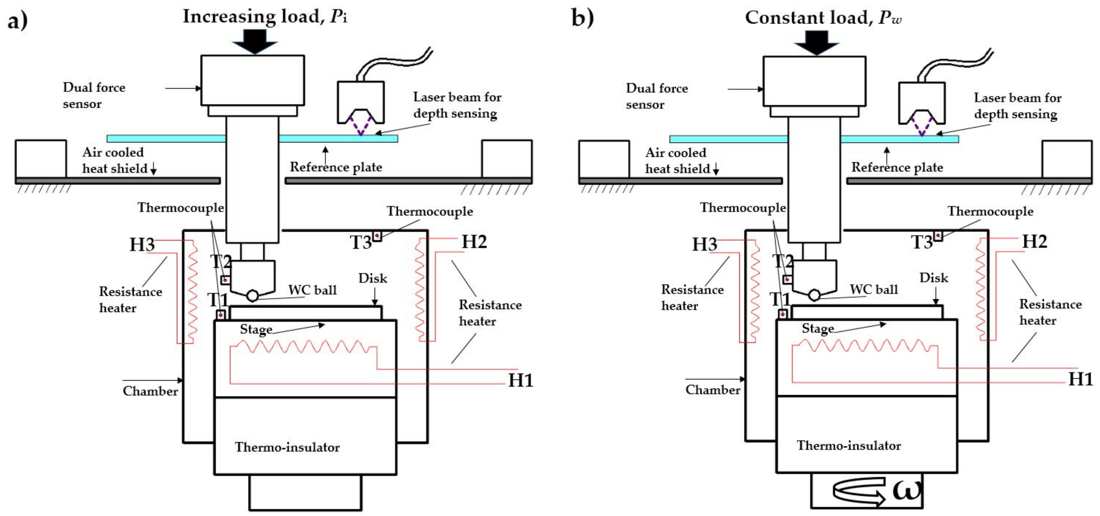
The joint test rig for high temperature micro-indentation and wear test was developed based on a Bruker CETR UMT-3 multifunction tribometer (Bruker, Billerica, MA, USA), as schematically shown in Figure 1. Balls of WC with a diameter of 1.588 mm and surface roughness, Ra, of 0.02 μm were used as the indenter tips and tribo-counterparts. The indented disk was fixed on specimen stage and heated by resistance heaters (labeled as H1) under the surface of stage. The thermocouple (labeled as T1) for controlling the sample temperature was placed 1 mm besides the disk. The thermocouple (labeled as T2) for measuring the indenter’s temperature was located 2 mm from WC ball. The thermocouple (labeled as T3) for controlling chamber temperature was placed on the cover of chamber. The resistance heaters (labeled as H2 and H3) for heating chamber were placed around the wall. Besides, an air-cooling thermal shield was placed between the chamber and loading cell for minimization of any heating of electronics in the loading cell. During indentation tests or wear tests, the temperature differences among T1, T2, and T3 was ensured to be less than 5 °C.
In indentation tests, the stage was kept stationary. The WC ball was pressed against tested surface under an increasing load, Pi, thus displacement occurred for the reference plate which was rigidly connected to the indenter, as shown in Figure 1a. The applied force, Pi, was measured by the load sensor (UMT, DFH-100-44163, scale 1000 N, resolution 0.01%, Bruker, Billerica, MA, USA). The displacement of the reference plate was recorded by the CCD laser sensor (LK-G10, scale ±1 mm, resolution 0.02%, Keyence, Osaka, Japan). In wear tests, the WC ball was pressed onto sample surface under a constant load, Pw, while the table was rotated at the given speed, ω.
2.3. Test Procedure
The parameters used in high temperature indentation and wear tests are shown in Table 1.
In the case of performing high temperature indentation tests, the WC ball was loaded against the tested surface at an initial load of 1 N. After a stabilization period about 300 s, the system was at thermal equilibrium. The loading and unloading rates were both 2 N/s. The peak load was 300 N. There was an additional holding at 10% of peak load at unloading stage for thermal drift correction. Indentation tests were performed at 25 °C, 200 °C, 315 °C, 400 °C and 500 °C for all samples. Six repetitions were carried out at each temperature to confirm the repeatability. The experimental parameters for the wear tests were as follows: the normal loads of 10 N, 15 N, and 25 N; a linear speed of 10.5 mm/s; a total of 900 revs for each tests. Wear tests were also performed at 25 °C, 200 °C, 315 °C, 400 °C and 500 °C for all samples. After the wear tests, scanning electron microscope (SEM, Quanta2000, Philips, Amsterdam, The Netherlands) and energy dispersive X-ray spectroscopy (EDS, EDAX-7760/68 ME, Ametek, Berwyn, PA, USA) were used to evaluate the wear scars.
2.4. Theoretical Background for Spherical Indentation
The measured displacement of the reference plate consisted of contact interference between WC ball and indented samples, elastic deformation of the testing frame, and thermal drift. In the present study, the linearity correction method [20] was valid for eliminating the effects of thermal drift and elastic deformation of the testing frame.
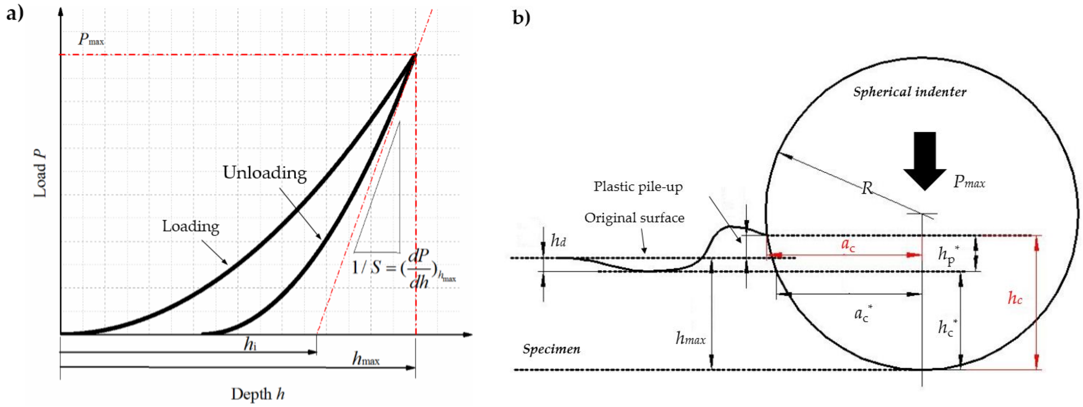
Figure 2a shows a typical indentation load–depth curve. For high alloy steels that have significant “plastic pile-up” generated in material during indention process, Figure 2b shows the typical indentation morphology by spherical indenter.
As shown in Figure 2a, the maximum depth, hmax, was the total displacement of the indented surface and the indenter at maximum load, Pmax. The slope of the unloading curve at Pmax was the indentation stiffness of the specimen and indenter, noted as 1/S. The intercept depth, hi, was obtained by extrapolating the tangent line of the initial unloading curve to P = 0. In addition, some indentation depths were defined from indentation morphology, as shown in Figure 2b. hc was the actual contact depth considering “plastic pile-up”. ac was the actual contact radius. The deflection depth, hd, was the depth to which the maximum indentation depth, hmax, was reduced by elastic deflection of the indented material. The difference of hmax and hd was the elastic contact depth, hc*. The increase in depth from hc* to hc by the “plastic pile-up” phenomenon was defined as hp*. Finally, the actual contact depth, hc, can be expressed as:
Kim et al. [21] studied the actual contact depth during spherical indentation of many kinds of tool steels. According to his study, the elastic contact depth, hc*, and the pile-up depth, hp*, could be expressed as:
where χ is a constant related to the indenter shape; χ = 0.75 for a spherical indenter. n is the working-hardening exponent for indented material, and n was set as 0.25 in the present study. R was the radius of the ball. Then, the composite hardness, Hsys, and composite elastic modulus, Er, of the CrN coating–M50 substrate system were determined as follows:
The composite hardness of coating–substrate system was thus the result of the two, coating and substrate, contributed. In order to determine the true hardness of the coating, it was necessary to separate these contributions. According to the model advanced by Puchi-Cabrera [22], the relationship between the composite hardness of coating–substrate system and the independent hardness of coating and substrate can be expressed as:
where Hs is the substrate hardness. Hc is the coatings hardness. Zr is the relative indentation depth, and Zr = 2ac/7tc. tc is the coating thickness. k and n are the constants characteristic of the coating–substrate system. Puchi-Cabrera [22] studied the indentation response of the CrN coated tool steel. According to his study, k and n were determined to be 2.3 and 0.25, respectively.
3. Results
3.1. Indentation Tests at Elevated Temperatures
Elevated temperature indentation test results of uncoated M50 disks, 2 μm CrN coated M50 disks and 5 μm CrN coated ones are shown in Figure 3.
Using Equations (1)–(5), hardness of M50 substrate, Hs, and composite hardness of CrN coated M50 disks, Hsys, were calculated from the load–depth curve shown Figure 3. Then, using Equation (6), the absolute hardness of 2 μm CrN coating and 5 μm CrN coating were calculated, as presented in Figure 4. In general, CrN coatings with all thicknesses showed a decreasing of hardness with temperatures. When the tested temperature was below 315 °C, the hardness of 2 μm thick CrN coating was higher than 5 μm thick CrN coating. However, when the tested temperature was above 400 °C, the 5 μm thick CrN coating had higher values in hardness. The 2 μm thick CrN coating had reduction of 49% in hardness values when the temperature increased from 25 to 500 °C. By comparison, the 5 μm thick CrN coating only had a reduction of 26%. It can be concluded that a thicker CrN coating would be helpful in maintaining the stability of surface hardness in high temperatures.
Figure 5 presents the loading curves and corresponding contact stress curves of 2 μm CrN coated M50 disks and 5 μm CrN coated ones in the load range of 1–50 N. The contact stress during indentation tests can be calculated using the following equation [23]:
where σ is mean contact stress, and ac is the contact radius during indentation.
In Figure 5a,c, the loading curves were continuous up to a certain load, at which a sudden displacement burst occurred, indicating the occurrence of “pop-in” behavior. According to Shao [24], the indentation stress-induced phase transition with material volume reduction (i.e., coating cracking) was the prerequisite to “pop-in” behavior. Hence, the indentation load, corresponding to the appearance of a “pop-in” event, could possibly be considered as an evaluation tool of load bearing capacity for the coating–substrate system. In another aspect, as shown in Figure 5b,d, it was found that the contact stress reached its maximum values at this indentation load. The external load corresponding to the “pop-in” behavior was named as the load bearing capacity, Lb, for a coating–substrate system.
It can be concluded that the load bearing capacities of CrN coated M50 disks decreased with temperatures. As illustrated in Figure 5a,b, for the 2 μm CrN coated M50 disks, a normal load of 10 N was always less than its load bearing load bearing capacity, Lb, in temperature range of 25–500 °C. However, an external load of 15 N was higher than its load bearing capacity when the temperature was elevated to 500 °C. An external load of 25 N was always higher than its load bearing capacity at any temperature. As illustrated in Figure 5c,d, for the 5 μm CrN coated M50 disks, an external load of 10 N, 15 N or 25 N was always less than its load bearing capacity in temperature range of 25–500 °C.
3.2. Tribological Responses
Figure 6a–f shows the friction coefficient curves and penetration depth during wear test of 5 μm CrN coated M50 disks as a function of temperatures under the tested loads of 10 N, 15 N, and 25 N. The variation of width of wear scars with temperatures is depicted in Figure 6g.
As illustrated in Figure 6a,c,e, running-in was presented by an increase of the friction coefficient during first several dozens to hundreds of cycles for all measured temperatures and loads. In the running-in stage, the friction force is mainly contributed to deform and fracture the contact asperities [25]. Due to the lower hardness of the coating material at higher tested temperature, it would take less number of cycles for the friction coefficient to reach the steady stage.
For 5 μm CrN coated M50 disks tested under each load, the stable values of friction coefficient were all found to be decreased with temperatures. At the temperatures of 25 °C and 200 °C, the friction coefficient was determined to be about 0.6. However, it decreased to 0.4 at 315 °C, then gradually decreased to the lowest value of 0.3 at the highest temperature of 500 °C.
As shown in Figure 6b,d,f, the variation trends of penetration depth at the temperatures above 315 °C were quite different from those at the temperatures below 200 °C. Due to the lower hardness of CrN coating at high temperatures, the penetrate depth increased more sharply at the temperatures above 315 °C than at the temperature below 200 °C in first 300 cycles. After 300 cycles of relative sliding, the penetration depth went on increasing linearly with distance at the temperatures below 200 °C, however, was much slowed down the temperatures above 315 °C. Meanwhile, the fluctuation in friction coefficient with sliding distance was also weakened when the tested temperatures were equal or above 315 °C. According to Polcar [11], the reduction of penetration depth at the temperatures above 315 °C might contributed to the self-lubricant function of the formed chromium oxide tribo-layer.
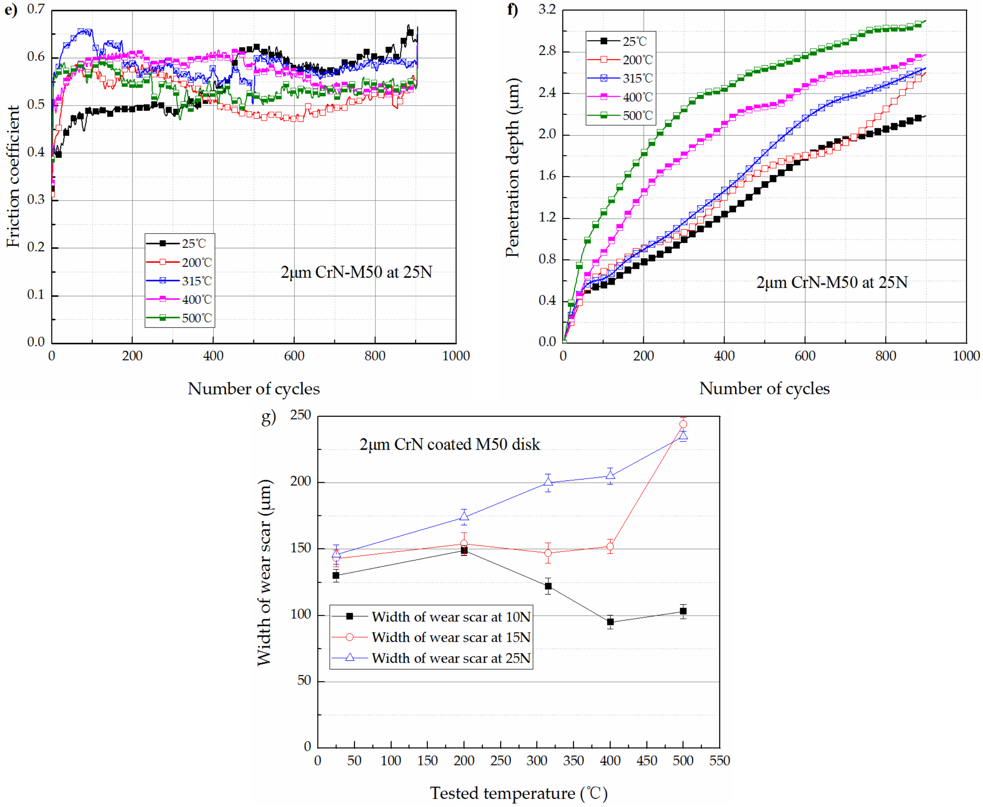
The high temperature tribological response of 2 μm CrN coated M50 disks under each tested loads were quite different from the 5 μm CrN coated M50 disks. Figure 7a–f shows the friction coefficient curves and penetration depth during wear test of 2 μm CrN coated M50 disks as a function of temperatures under the tested loads of 10 N, 15 N and 25 N. The variation of width of wear scars with temperatures is depicted in Figure 7g.
As shown in Figure 6a and Figure 7a, under the tested load of 10 N, the stable values of friction coefficients of 2 μm CrN coated M50 samples were similar to those of the 5 μm CrN coated M50 samples at each tested temperatures. As shown in Figure 7c, under the applied load of 15 N, the friction coefficients of 2 μm CrN coated M50 samples were still similar to those for the 5 μm CrN coated M50 samples when the tested temperatures were equal or below 400 °C. However, at the tested temperature of 500 °C, the friction coefficient substantially increased from 0.25 to 0.55 during the wear test. As shown in Figure 7e, under the applied load of 25 N, the values of friction coefficients at each temperatures were all above 0.5. As shown in Figure 7g, the width of wear scars was found to be always increased with the tested temperatures under the tested load of 25 N.
As shown in Figure 7b, the variation trends of penetration depth with temperatures of 2 μm CrN coated M50 samples was similar to 5 μm CrN coated ones. As shown in Figure 7d, when the tested load was increased to 15 N which was above the load bearing capacity of the 2 μm CrN coated M50 disks at 500 °C, the penetration depth substantially increased at about 700 cycles. It should be noted that the friction coefficient was also substantially increased at about 700 cycles. As shown in Figure 7f, under an applied load of 25 N which exceed the load bearing capacity of the 2 μm CrN coated M50 disks at any tested temperatures, the wear reduction function of chromium oxide tribo-layer failed. It can be observed that the wear rate always increased with temperatures under the load of 25 N for the 2 μm CrN coated M50 disks.
3.3. Morphology and EDS Results of Worn Surfaces
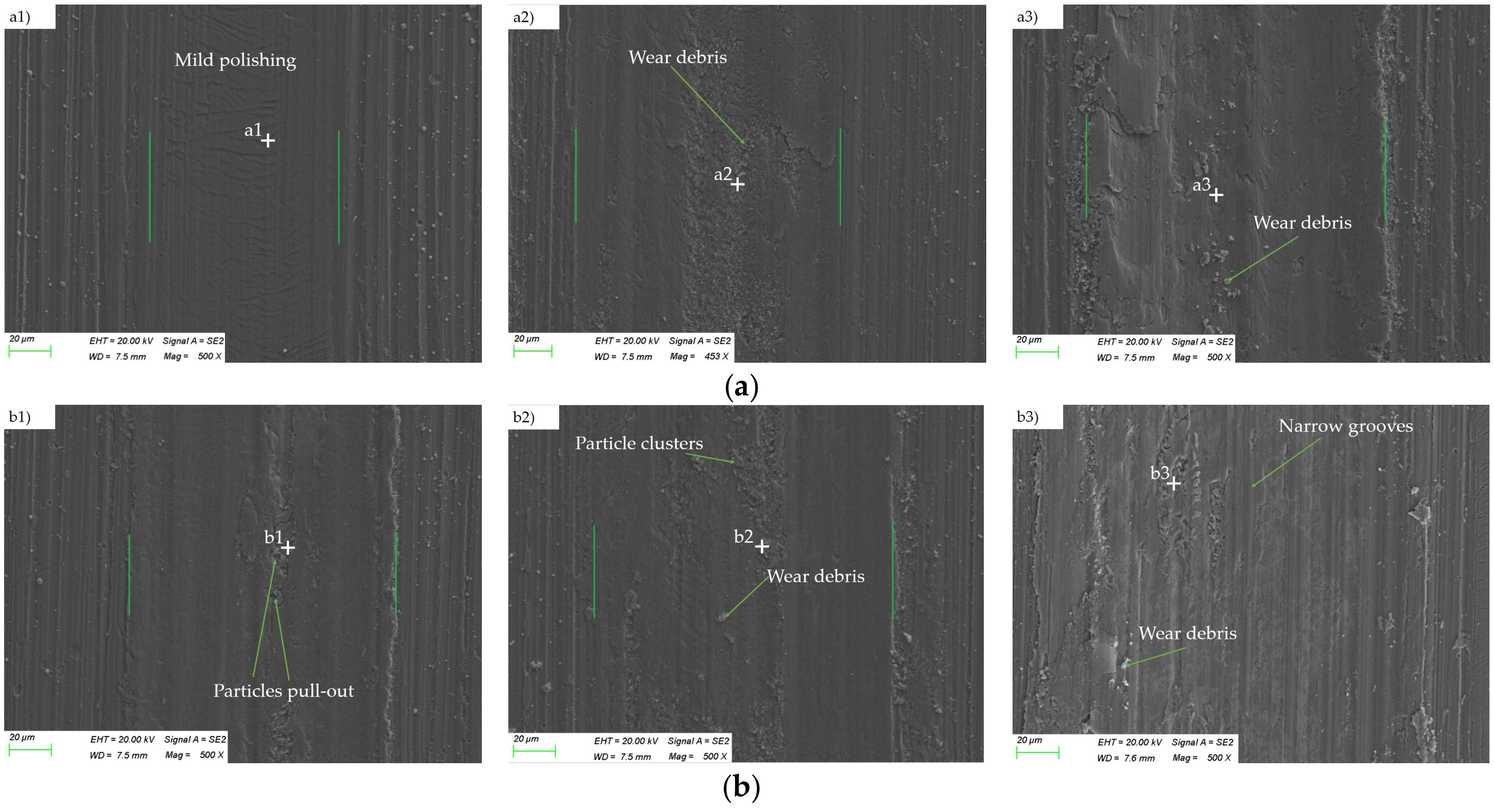
Figure 8 showed the morphology of worn tracks on 5 μm CrN coated M50 disks under various loads at the temperatures of 25 °C and 200 °C. Small pits, narrow grooves parallel to the sliding direction, and wear debris were detected on the worn surfaces. EDS was used to identify the chemical compositions in different zones, and the results are listed in Table 2.
The EDS analysis results (at.%) revealed that the worn tracks contained primarily Cr and N after 900 cycles of relative sliding at 25 °C or 200 °C. More importantly, a few W were detected in the worn tracks. It can be confirmed that slight material removal occurred for CrN coatings and WC ball during wear testing at 25 °C and 200 °C, indicating that the dominant wear mechanism at these two temperatures was mild abrasive wear.
In addition to the decreasing of friction coefficient, the morphology of worn tracks at the temperatures above 315 °C was also much different from those at the temperatures below 315 °C. Figure 9 shows the morphology of wear tracks on 5 μm CrN coated M50 disks when the temperatures were equal or above 315 °C. In Figure 9a, it can be noticed that the worn tracks were quite smooth after sliding at 315 °C for 900 cycles under each tested loads. In Figure 9b,c, it can be noticed that the worn surfaces were roughened with oxidized clusters. However, small pits, narrow grooves, and wear debris almost disappeared on the worn surfaces. SEM observation of wear tracks confirmed the existence of tribo-layers with lamellae structure over the worn tracks when wear tests on CrN coatings were performed at the temperatures above 315 °C.
EDS analysis results are listed in Table 3. It can be observed that the O contents approached or surpassed that of N in the worn area after 900 cycles of relative sliding at 315 °C, 400 °C or 500 °C. Meanwhile, the worn area contained primarily Cr and O. This meant that a mass of tribo-oxides formed on worn surfaces. As referred above [12], the oxidation of PVD CrN coating material started at the temperature around 300 °C. More importantly, a few W were detected in the worn area, indicating that the oxide film can prevent the adhesion between CrN coating and WC ceramic ball and possess self-lubricant function. Thus, the friction coefficient and width of wear scars decreased at 315 °C. It is clear that wear of CrN coating at temperatures equal or above 315 °C was mild oxidative wear.
It can be concluded that, for 5 μm CrN coated M50 disks, the dominant wear mechanism transitioned from mild abrasive wear to mild oxidation wear when the temperatures were above 315 °C.
Figure 10 presents the morphology of worn tracks on 2 μm CrN coated M50 disks under various loads at the temperatures of 25 °C and 200 °C. As shown in Figure 10a1,a2,b1,b2, under the applied load of 10 N or 15 N, the worn tracks on 2 μm CrN coated M50 disks and the worn tracks on 5 μm CrN coated M50 disks presented similar morphology. The dominant wear mechanism for the 2 μm CrN coated M50 samples under the applied load of 10 N or 15 N was mild abrasive wear, corresponding to smooth worn surfaces with wear debris and narrow grooves presented in the worn area. However, when the load was increased to 25 N, local coating fracture can be observed on the edge of the wear scars for the 2 μm CrN coated M50 disks, as illustrated in Figure 10a3,b3. EDS analysis results are listed in Table 4. EDS analysis of the coating delamination area (Points a3, b3) confirmed the significant increasing of Fe element, indicating the partial detachment of coating material. The results above indicated that, at lower tested temperatures, the wear of CrN coatings transitioned from mild abrasive wear to the coating fracture controlled wear when the applied load exceeded its the load carrying capacity.
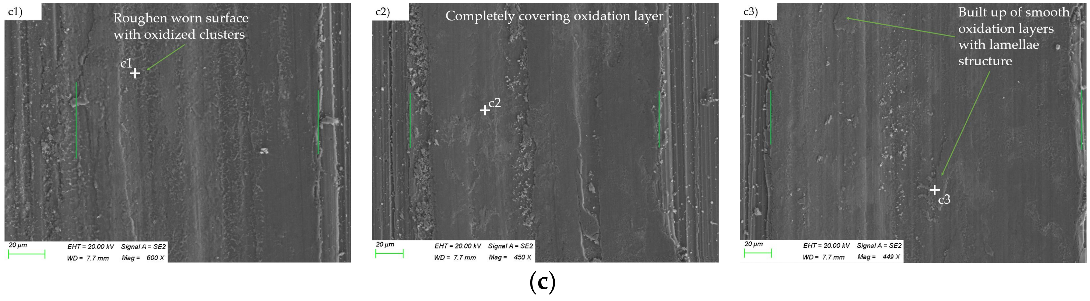
Figure 11 shows the morphology of worn tracks on 2 μm CrN coated M50 disks when the tested temperatures were equal or above 315 °C. As shown in Figure 11a1,b1,c1, under a tested load of 10 N, the dominant wear mechanism for the 2 μm CrN coated M50 samples was mild-oxidation wear when the tested temperatures were above 315 °C. In additional, under a tested load of 15 N, the wear of 2 μm CrN coated M50 samples could still be characterized as mild-oxidation wear at the temperature of 315 °C and 400 °C, as illustrated in Figure 11a2,b2. However, when the tested temperature was elevated to 500 °C, the oxidation layers were stripped from the surface of coating under the applied load of 15 N, as illustrated in Figure 11c2. It should be pointed out that the external load of 15 N just exceeded the load-bearing limitation of 2 μm CrN coated M50 disk at the temperature of 500 °C, as shown in Figure 5c,d. While the tested load was increased to 25 N, no obvious oxidation layers were detected after wear tests at temperatures of 315 °C, 400 °C and 500 °C, as illustrated in Figure 11c3,d3,e3.
EDS analysis results are listed in Table 5. EDS analysis of Points a3, b3, and c3 revealed that the contents of Fe, O significantly surpassed that of Cr, N in the worn area after 900 cycles of relative sliding under the load of 25 N at 315 °C, 400 °C or 500 °C. This indicated the severe materials removal occurred for CrN coatings, thereby leading to exposure of M50 substrate. Besides, it can be noticed that there were delaminated regions and oxidation clusters in a widespread dispersion on the worn tracks. It can be conclude that, at higher tested temperatures, the wear of CrN coated M50 steel transitioned from mild oxidation wear to the compound wear mechanisms containing oxidative wear, coating delamination or adhesive wear when the external load exceeded its load bearing capacities. This was also the key reason why the high temperature friction coefficient of the 2 μm CrN coated M50 samples suddenly increased under the tested load of 25 N.
4. Discussion
The lubricating function of chromium oxide film were further utilized by many researchers to develop the so-called “chameleon” coating for high temperature application, such as CrN–Ag [26]. For those CrN based hard composited coatings, the soft metal possessed solid lubricating function at lower temperatures, while the chromium oxide tribo-layer possessed lubricating function at higher temperatures. It is provn that formed chromium oxide film was found to provide a long endurance and friction coefficients within 0.3–0.4 at 400–500 °C in air [27]. This was coincidence with the present study. However, Voevodin et al. [28] argued that, to develop the “chameleon” coating with better temperature-adaptive property, the functional temperature range of soft metal lubricating and chromium oxide film lubricating should be with certain degrees of overlapping. In this study, it was found that the chromium oxide film lubricating started at temperature about 300 °C. Furthermore, we believe that this conclusion would be useful in the CrN based hard composited coating design.
Many researchers also concerned on the critical load for high temperature application of CrN coating or CrN based temperature-adaptive coating. In this study, the high temperature indentation test was employed to study the load bearing capacity of CrN coating–substrate system, and it was found that the obtained load bearing capacity can be cited as the critical load for high temperature application of CrN coatings. The failure mechanism of the chromium oxide film is summarized as follows.
Taking the 2 μm CrN coated M50 disks as an example, under an external load of 15 N, which just exceeded its load bearing capacity at 500 °C, the stripping and piling up of the oxide film was observed, as illustrated in Figure 11c2. As pointed by Holmberg [29], this kind of thin film failure is related to the tensile fracture and subsequently detachment from the interface. Cracks on the interface were an essential factor triggering this kind of failure. SEM observation verified that radical cracks were generated on the coating surface when the 2 μm CrN coated M50 disk was indented under a load of 15 N at 500 °C (see Figure 12).
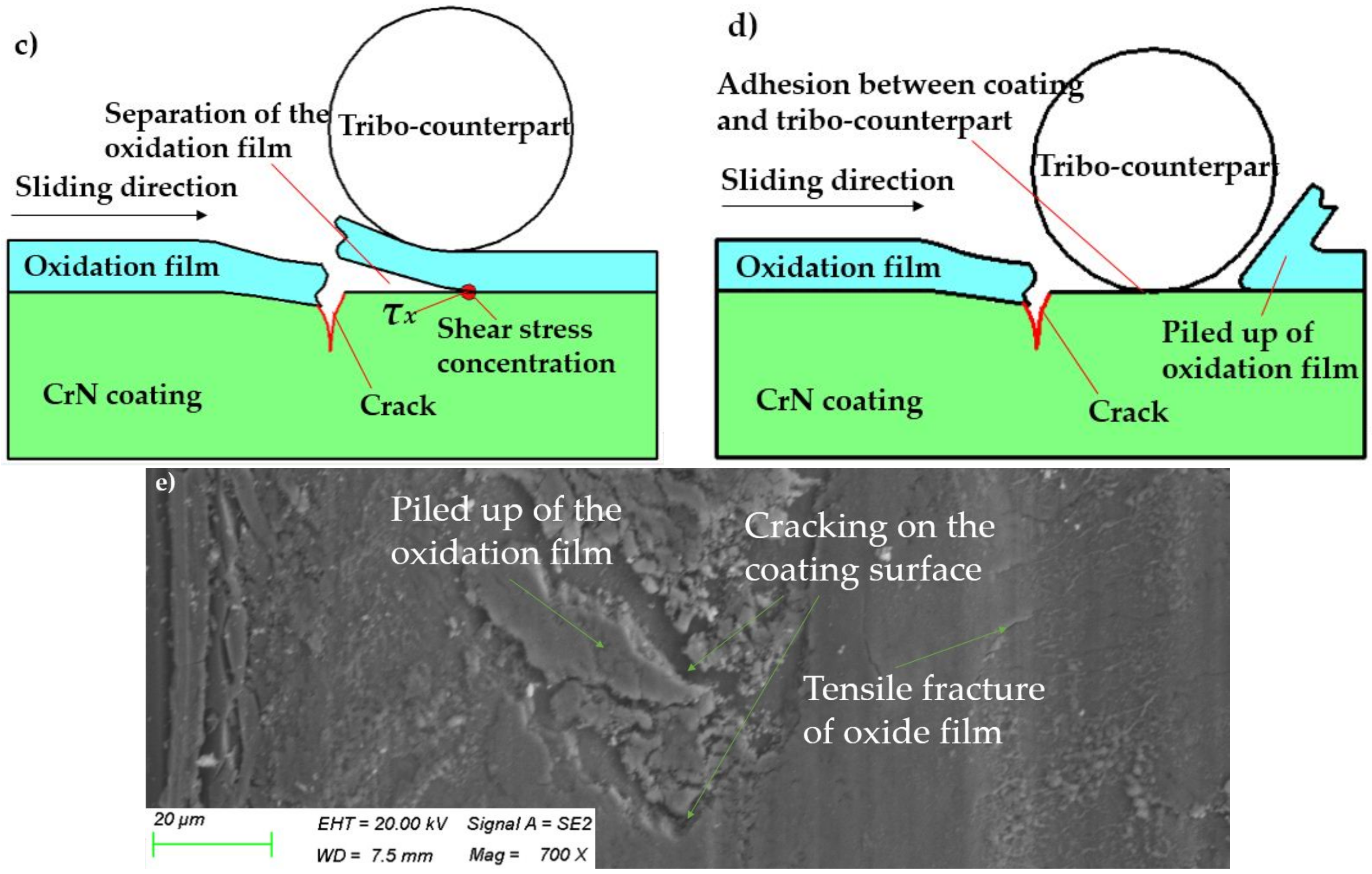
The chromium oxide film would act as a cantilever beam when cracks were on the surface of CrN coating. The stress concentration would be generated in the center of the cantilever beam, as shown in Figure 13a, thereby resulting in the tensile fracture of the oxide film, as depicted in Figure 13b. Then, shear stress concentration would be generated on the interface between the chromium oxide film and CrN coating surface. The shear stress concentration finally resulted in the separation of the oxide film from the coating surface, as illustrated in Figure 13c. As the failure of oxidation film occurred, the adhesion between coating material and tribo-counterpart occurred, resulting in the wear transition for CrN coated M50 steel, as illustrated in Figure 13d. The failure mechanisms for the oxide film was also confirmed by the morphology of wear tracks on 2 μm CrN coated M50 disks at the load of 15 N and temperature of 500 °C, as shown in Figure 13e.
In the current study, four types of wear were detected for the CrN coated M50 disks under various of loads and temperatures: abrasive wear; mild oxidation wear; coating fracture controlled wear; and the compound wear mechanisms containing oxidative wear, coating delamination or adhesive wear. According to the above discussion, the characteristics of wear transition for CrN coated M50 steel at elevated temperatures are summarized in Table 6.
5. Conclusions
The combination of high temperature spherical indentation and wear test provides a useful and unique way to study the relationships between operating conditions and wear mechanisms of CrN coating at elevated temperatures. The main conclusions are summarized as follows:
- The hardness of CrN coating decrease with temperatures: When the tested temperature was below 315 °C, the hardness of 2 μm thick CrN coating was higher than 5 μm thick CrN coating. However, when the tested temperature was above 400 °C, the 5 μm thick CrN coating had higher values in hardness. A thicker CrN coating would be helpful in maintaining the stability of surface hardness in high temperatures.
- Wear of CrN coating changes with external load, P, and temperature, T: Under the tested condition of P < Lb and T < 315 °C, abrasive is the dominant wear mechanism for CrN coating. With a tested condition of P < Lb and T ≥ 315 °C, wear of CrN coating transitions into mild oxidation wear due to the lubrication effect of oxidation layers. Under the tested condition of P > Lb and T < 315 °C, wear of CrN coating was controlled by coating fracture. Under the tested condition of P > Lb and T ≥ 315 °C, wear of CrN coating transitions into the severe wear mode with a combination of detachment, adhesion and oxidation, due to the tensile fracture of oxidation films, thereby leading adhesion between CrN coating and tribo-counterpart.
- The presented analysis method can be helpful in predicting the permissible loads for a CrN coating–M50 substrate system at the given temperature. To conclude, it can be helpful in the tribological design for CrN coatings and allow the rational selection of coating thickness for a particular high temperature application.
Acknowledgments
This work was supported by the National Natural Science Foundation of China (Grant No. 51675120).
Author Contributions
Guangze Tang contributed the deposition of CrN coatings. Le Gu contributed to the discussion of failure mechanism of chromium oxide film. Yuze Mao contributed to the SEM observation and EDS analysis. Chi Zhang analyzed the test results and wrote the paper.
Conflicts of Interest
The authors declare no conflicts of interest.
References
- Gilewicz, A.; Chmielewska, P.; Murzynski, D.; Dobruchowska, E.; Warcholinski, B. Corrosion resistance of CrN and CrCN/CrN coatings deposited using catholic arc evaporation in Ringer’s and Hank’s solutions. Surf. Coat. Technol. 2016, 299, 7–14. [Google Scholar] [CrossRef]
- Podgornik, B.; Sedlaček, M.; Mandrino, D. Performance of CrN coatings under boundary lubrication. Tribol. Int. 2016, 96, 247–257. [Google Scholar] [CrossRef]
- Ding, J.; Zhang, T.; Yun, J.M.; Kang, M.C.; Wang, Q.; Kim, K.H. Microstructure, mechanical, oxidation and corrosion properties of the Cr-Al-Si-N Coatings deposited by a hybrid sputtering system. Coatings 2017, 7, 119. [Google Scholar] [CrossRef]
- Khanna, R.; Ong, J.L.; Oral, E.; Narayan, R.J. Progress in wear resistant materials for total hip arthroplasty. Coatings 2017, 7, 99. [Google Scholar] [CrossRef]
- Ramadoss, R.; Kumar, N.; Dash, S.; Arivuoli, D.; Tyagi, A.K. Wear mechanism of CrN/NbN super lattice coating sliding against various counter-bodies. Int. J. Refract. Met. Hard Mater. 2013, 41, 547–552. [Google Scholar] [CrossRef]
- Silva, F.; Martinho, R.; Andrade, M.; Baptista, A.; Alexandre, R. Improving the wear resistance of moulds for the injection of glass fibre-reinforced plastics using PVD coatings: A comparative study. Coatings 2017, 7, 28. [Google Scholar] [CrossRef]
- Gouveia, R.M.; Silva, F.J.G.; Reis, P.; Baptista, A.P.M. Machining duplex stainless steel: Comparative study regarding end mill coated tools. Coatings 2016, 6, 51. [Google Scholar] [CrossRef]
- Kawahara, Y. An overview on corrosion-resistant coating technologies in biomass/waste-to-energy plants in recent decades. Coatings 2016, 6, 34. [Google Scholar] [CrossRef]
- Lim, S.C.; Ashby, M.F. Overview No. 55 wear mechanism maps. Acta Metall. 1987, 35, 1–24. [Google Scholar] [CrossRef]
- Wang, Y.; Stephen, M.H. Wear and wear transition mechanisms of ceramics. Wear 1996, 195, 112–122. [Google Scholar] [CrossRef]
- Polcar, T.; Parreira, N.M.G.; Novák, R. Friction and wear behaviour of CrN coating at temperatures up to 500 °C. Surf. Coat. Technol. 2007, 201, 5228–5235. [Google Scholar] [CrossRef]
- Qi, Z.; Liu, B.; Wu, Z.; Zhu, F.; Wang, Z.; Wu, C. A comparative study of the oxidation behavior of Cr2N and CrN coatings. Thin Solid Films 2013, 544, 515–520. [Google Scholar] [CrossRef]
- Mandrino, D.; Podgornik, B. XPS investigations of tribofilms formed on CrN coatings. Appl. Surf. Sci. 2017, 396, 554–559. [Google Scholar] [CrossRef]
- Scheerer, H.; Hoche, H.; Broszeit, E.; Berger, C. Tribological properties of sputtered CrN coatings under dry sliding oscillation motion at elevated temperatures. Surf. Coat. Technol. 2001, 142–144, 1017–1022. [Google Scholar] [CrossRef]
- Beake, B.D.; Fox-Rabinovich, G.D.; Veldhuis, S.C.; Goodes, S.R. Coating optimization for high speed machining with advanced nanomechanical test methods. Surf. Coat. Technol. 2009, 203, 1919–1925. [Google Scholar] [CrossRef]
- Smith, J.F.; Zheng, S. High temperature nanoscale mechanical property measurements. Surf. Eng. 2000, 16, 143–146. [Google Scholar] [CrossRef]
- Everitt, N.M.; Davies, M.I.; Smith, J.F. High temperature nanoindentation—The importance of isothermal contact. Philos. Mag. 2011, 91, 1221–1244. [Google Scholar] [CrossRef]
- Sander, T.; Tremmel, S.; Wartzack, S. A modified scratch test for the mechanical characterization of scratch resistance and adhesion of thin hard coatings on soft substrates. Surf. Coat. Technol. 2011, 206, 1873–1878. [Google Scholar] [CrossRef]
- Ghosh, S.; Yadav, S.; Das, G. Ball Indentation Technique: A currently developed tool to study the effect of various heat treatments on the mechanical properties of En24 steel. Mater. Lett. 2008, 62, 3966–3968. [Google Scholar] [CrossRef]
- Wheeler, J.M.; Armstrong, D.E.J.; Heinz, W.; Schwaiger, R. High temperature nanoindentation: The state of the art and future challenges. Curr. Opin. Solid State Mater. Sci. 2015, 19, 354–366. [Google Scholar] [CrossRef]
- Kim, S.H.; Lee, B.W.; Choi, Y.; Kwon, D. Quantitative determination of contact depth during spherical indentation of metallic materials—A FEM study. Mater. Sci. Eng. A 2006, 415, 59–65. [Google Scholar] [CrossRef]
- Puchi-Cabrera, E.S. A new model for the computation of the composite hardness of coated systems. Surf. Coat. Technol. 2002, 160, 177–186. [Google Scholar] [CrossRef]
- Kot, M.; Rakowski, W.; Lackner, J.M.; Major, L. Analysis of spherical indentations of coating-substrate systems: Experiments and finite element modeling. Mater. Des. 2013, 43, 99–111. [Google Scholar] [CrossRef]
- Huang, X.; Etsion, I.; Shao, T.M. Indentation pop-in as a potential characterization of weakening effect in coating/substrate systems. Wear 2015, 338–339, 325–331. [Google Scholar] [CrossRef]
- Mo, J.L.; Zhu, M.H. Sliding tribological behaviors of PVD CrN and AlCrN coatings against Si3N4 ceramic and pure titanium. Wear 2009, 267, 874–881. [Google Scholar] [CrossRef]
- Mulligan, C.P.; Papi, P.A.; Gall, D. Ag transport in CrN–Ag nanocomposite coatings. Thin Solid Films 2012, 520, 6774–6779. [Google Scholar] [CrossRef]
- Mulligan, C.P.; Blanchet, T.A.; Gall, D. CrN–Ag nanocomposite coatings: High-temperature tribological response. Wear 2010, 269, 125–131. [Google Scholar] [CrossRef]
- Voevodin, A.A.; Muratore, C.; Aouadi, S.M. Hard coatings with high temperature adaptive lubrication and contact thermal management: Review. Surf. Coat. Technol. 2014, 257, 247–265. [Google Scholar] [CrossRef]
- Matthews, A.; Franklin, S.; Holmberg, K. Tribological coatings: Contact mechanisms and selection. J. Phys. D Appl. Phys. 2007, 40, 5463–5475. [Google Scholar] [CrossRef]
Figure 1.
Schematic of the joint test rig for high temperature micro-indentation and wear test: (a) for indentation test; (b) for wear test.
Figure 1.
Schematic of the joint test rig for high temperature micro-indentation and wear test: (a) for indentation test; (b) for wear test.

Figure 2.
The typical load–depth curve and indentation morphology by spherical indenter: (a) the typical load–depth curve; (b) the typical indentation morphology by spherical indenter for steels.
Figure 2.
The typical load–depth curve and indentation morphology by spherical indenter: (a) the typical load–depth curve; (b) the typical indentation morphology by spherical indenter for steels.

Figure 3.
Load–depth curves of the samples as a function of temperatures: (a) uncoated M50 disk; (b) 2 μm CrN coated M50 disk; and (c) 5 μm CrN coated M50 disk.
Figure 3.
Load–depth curves of the samples as a function of temperatures: (a) uncoated M50 disk; (b) 2 μm CrN coated M50 disk; and (c) 5 μm CrN coated M50 disk.
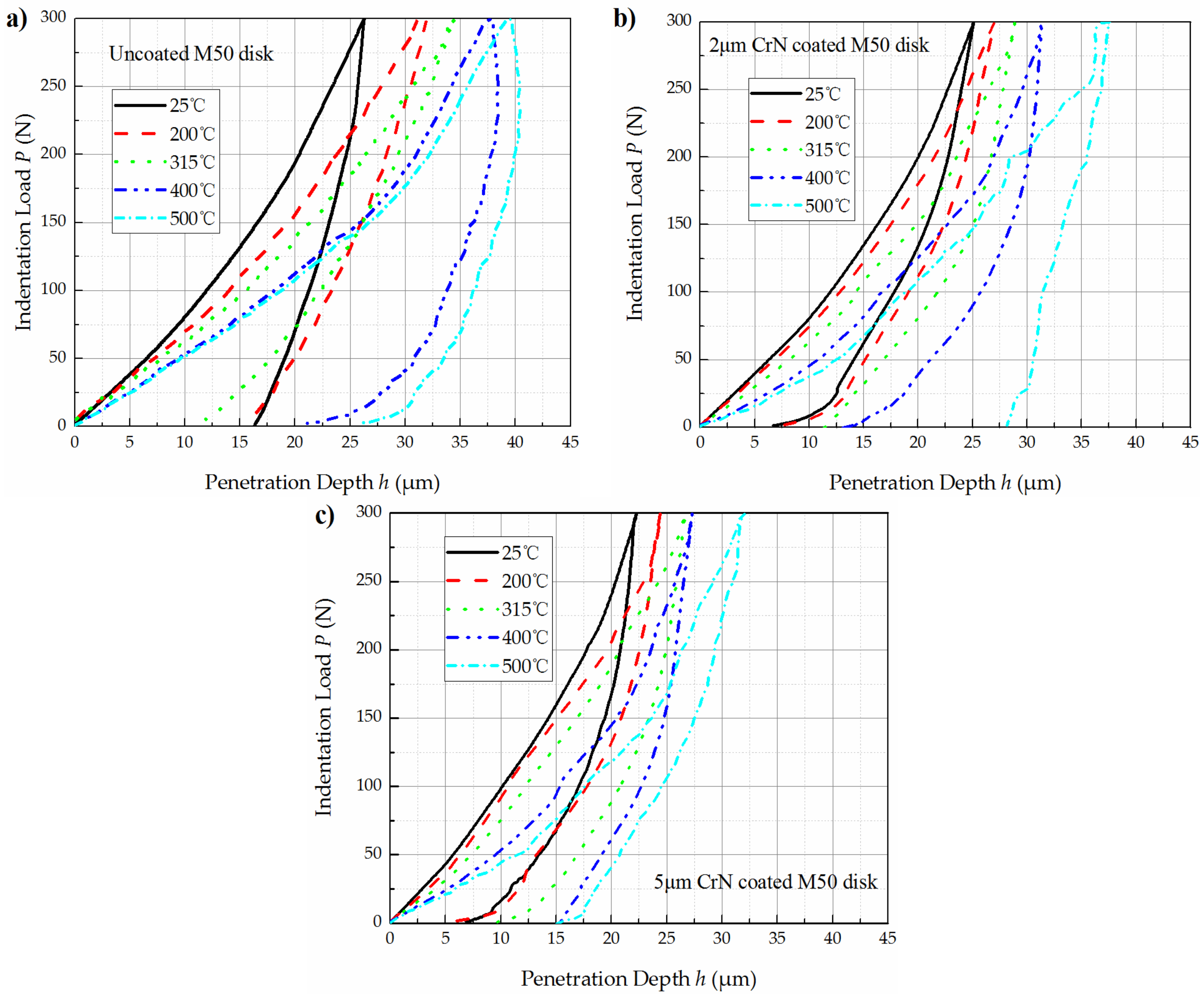
Figure 4.
Hardness of CrN coating as a function of temperatures.
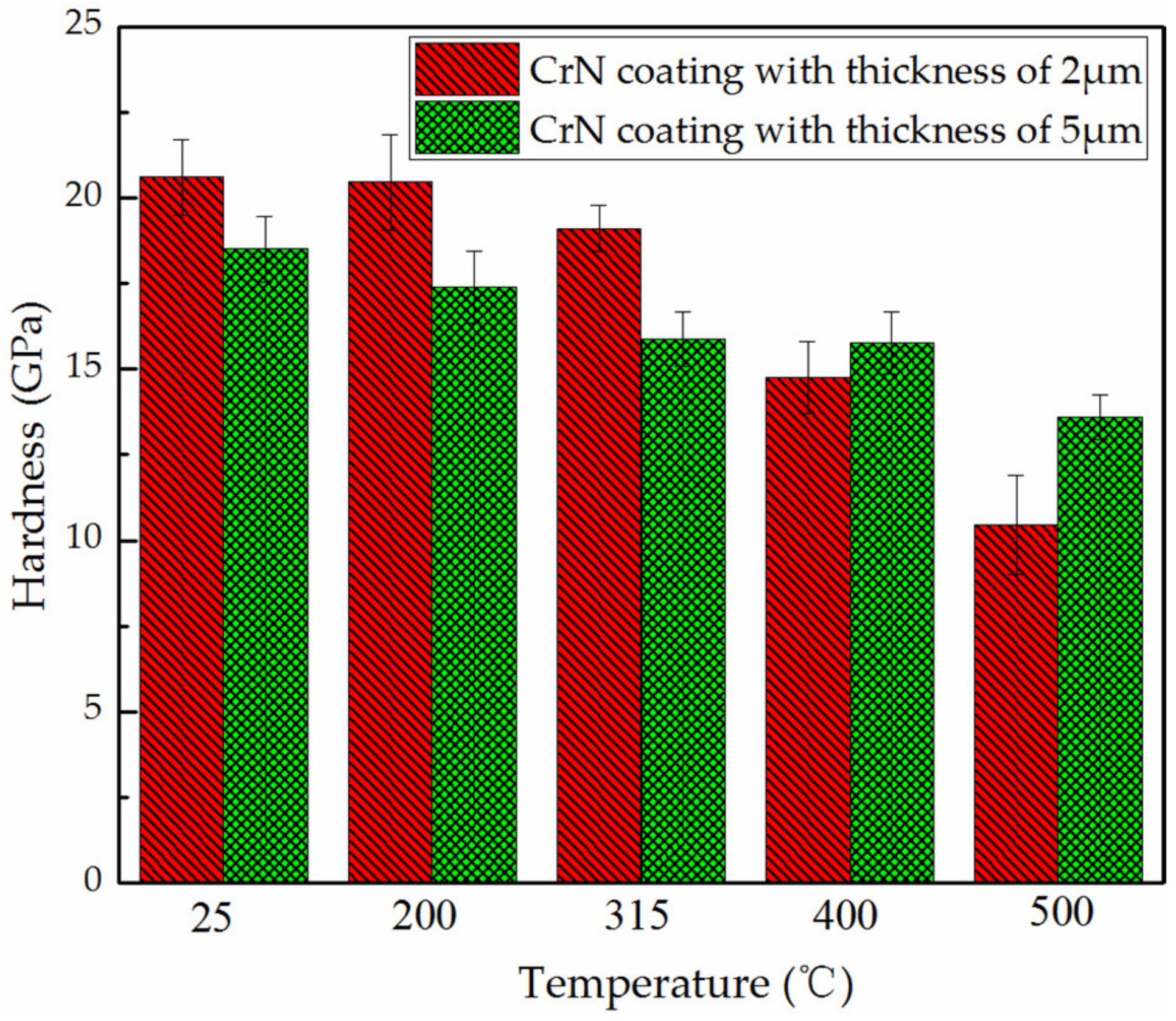
Figure 5.
Loading curves and corresponding contact stress curves of the samples as a function of temperatures in the load range of 1–50 N: (a) loading curves of 2 μm CrN coated M50 disk; (b) contact stress curves of 2 μm CrN coated M50 disk; (c) loading curves of 5 μm CrN coated M50 disk; and (d) contact stress curves of 5 μm CrN coated M50 disk.
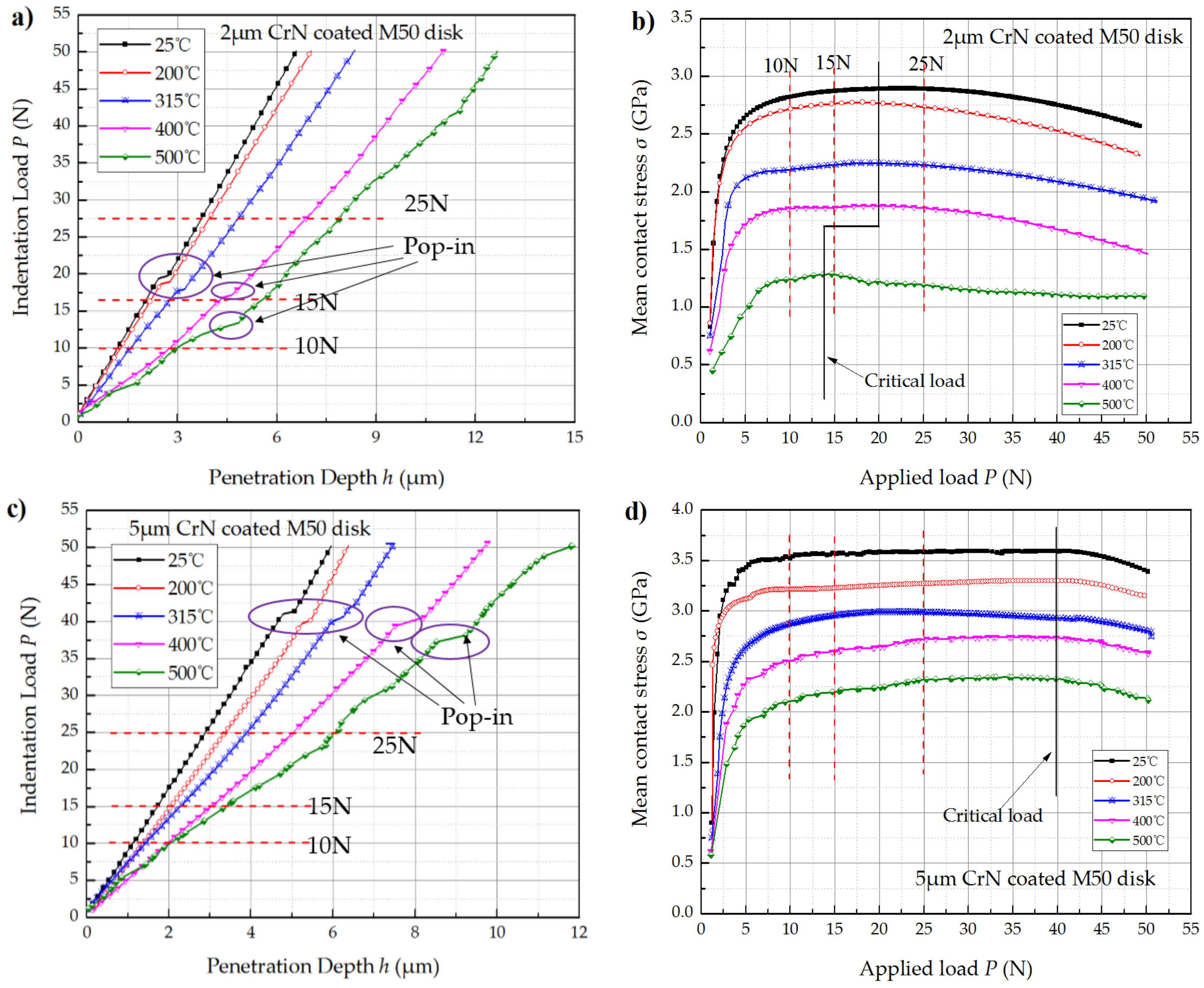
Figure 6.
Friction coefficient curves and penetration depth during wear test of the 5 μm CrN coated M50 disks: (a) variation of friction coefficient with temperatures under 10 N; (b) variation of penetration depth with temperatures under 10 N; (c) variation of friction coefficient with temperatures under 15 N; (d) variation of penetration depth with temperatures under 15 N; (e) variation of friction coefficient with temperatures under 25 N; (f) variation of penetration depth with temperatures under 25 N; and (g) variation of width of wear scars with temperatures.
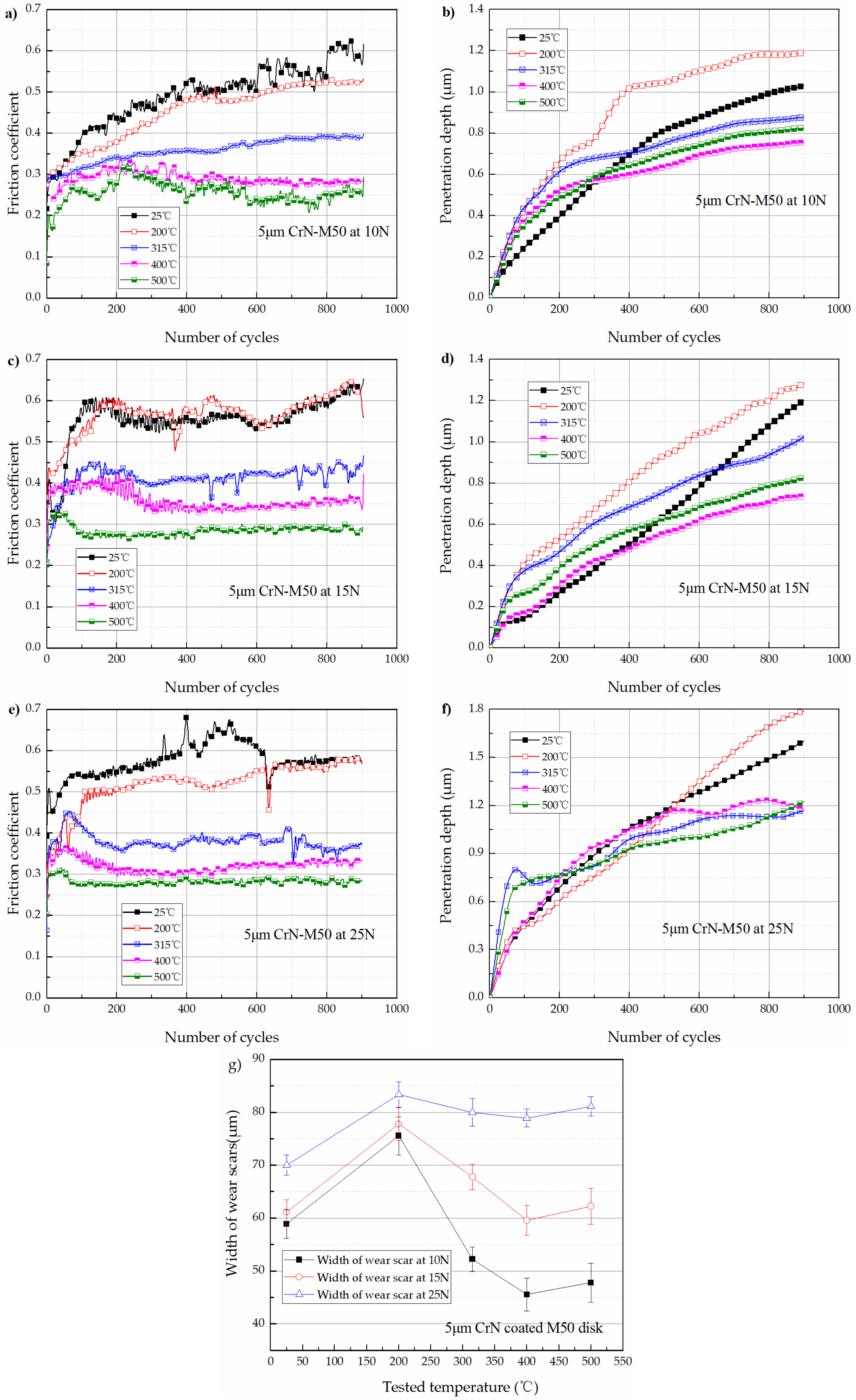
Figure 7.
Friction coefficient curves and penetration depth during wear test of the 2 μm CrN coated M50 disks: (a) variation of friction coefficient with temperatures under 10 N; (b) variation of penetration depth with temperatures under 10 N; (c) variation of friction coefficient with temperatures under 15 N; (d) variation of penetration depth with temperatures under 15 N; (e) variation of friction coefficient with temperatures under 25 N; (f) variation of penetration depth with temperatures under 25 N; and (g) variation of width of wear scars with temperatures.
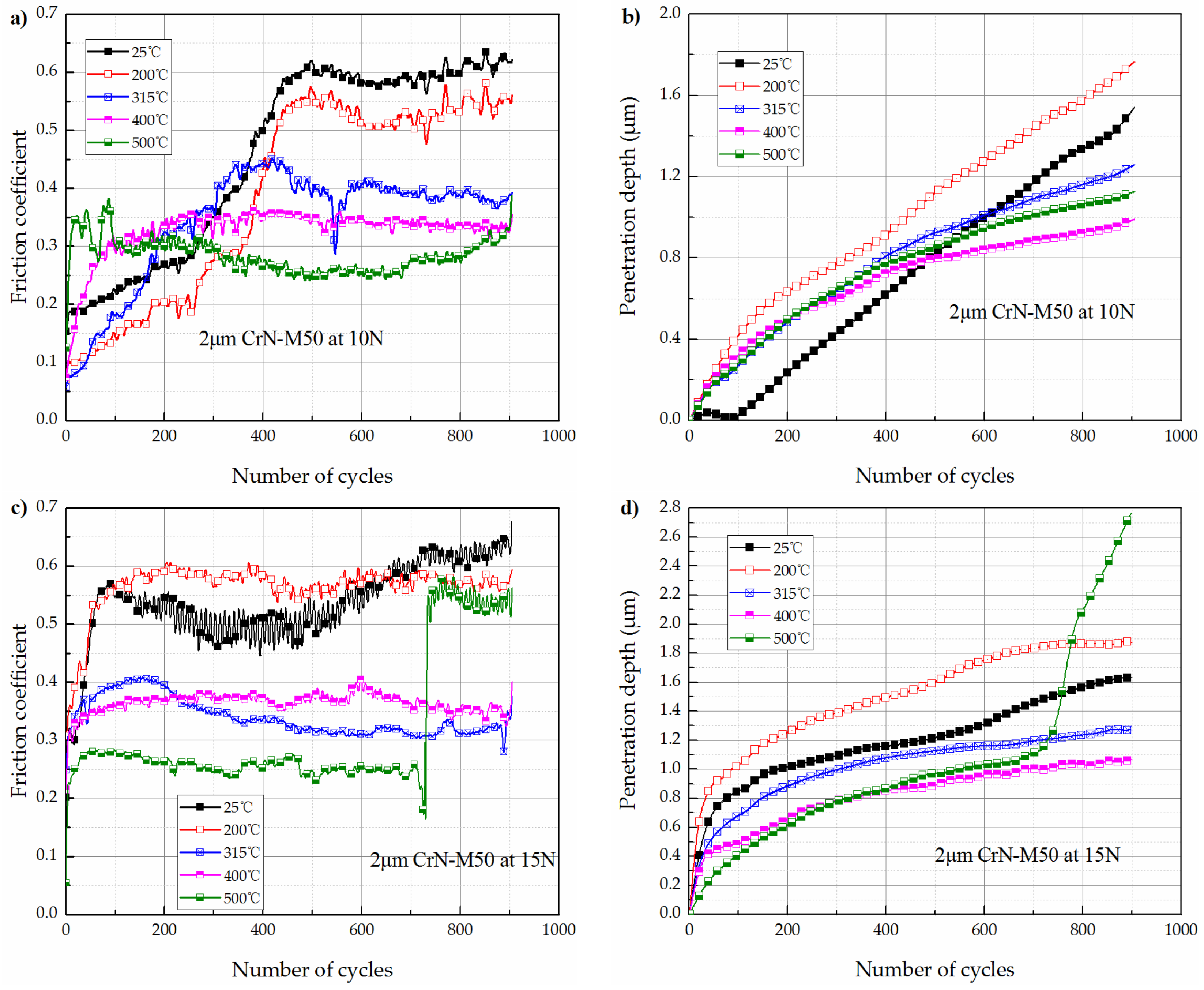

Figure 8.
Morphology of the worn tracks on 5 μm CrN coated M50 disks: (a) at the temperature of 25 °C under the load of (a1) 10 N, (a2) 15 N, and (a3) 25 N; and (b) at the temperature of 200 °C under the load of (b1) 10 N, (b2) 15 N, and (b3) 25 N.
Figure 8.
Morphology of the worn tracks on 5 μm CrN coated M50 disks: (a) at the temperature of 25 °C under the load of (a1) 10 N, (a2) 15 N, and (a3) 25 N; and (b) at the temperature of 200 °C under the load of (b1) 10 N, (b2) 15 N, and (b3) 25 N.

Figure 9.
Morphology of the worn tracks on 5 μm CrN coated M50 disks: (a) at the temperature of 315 °C under the load of (a1) 10 N, (a2) 15 N, and (a3) 25 N; (b) at the temperature of 400 °C under the load of (b1) 10 N, (b2) 15 N, and (b3) 25 N; and (c) at the temperature of 500 °C under the load of (c1) 10 N, (c2) 15 N, and (c3) 25 N.
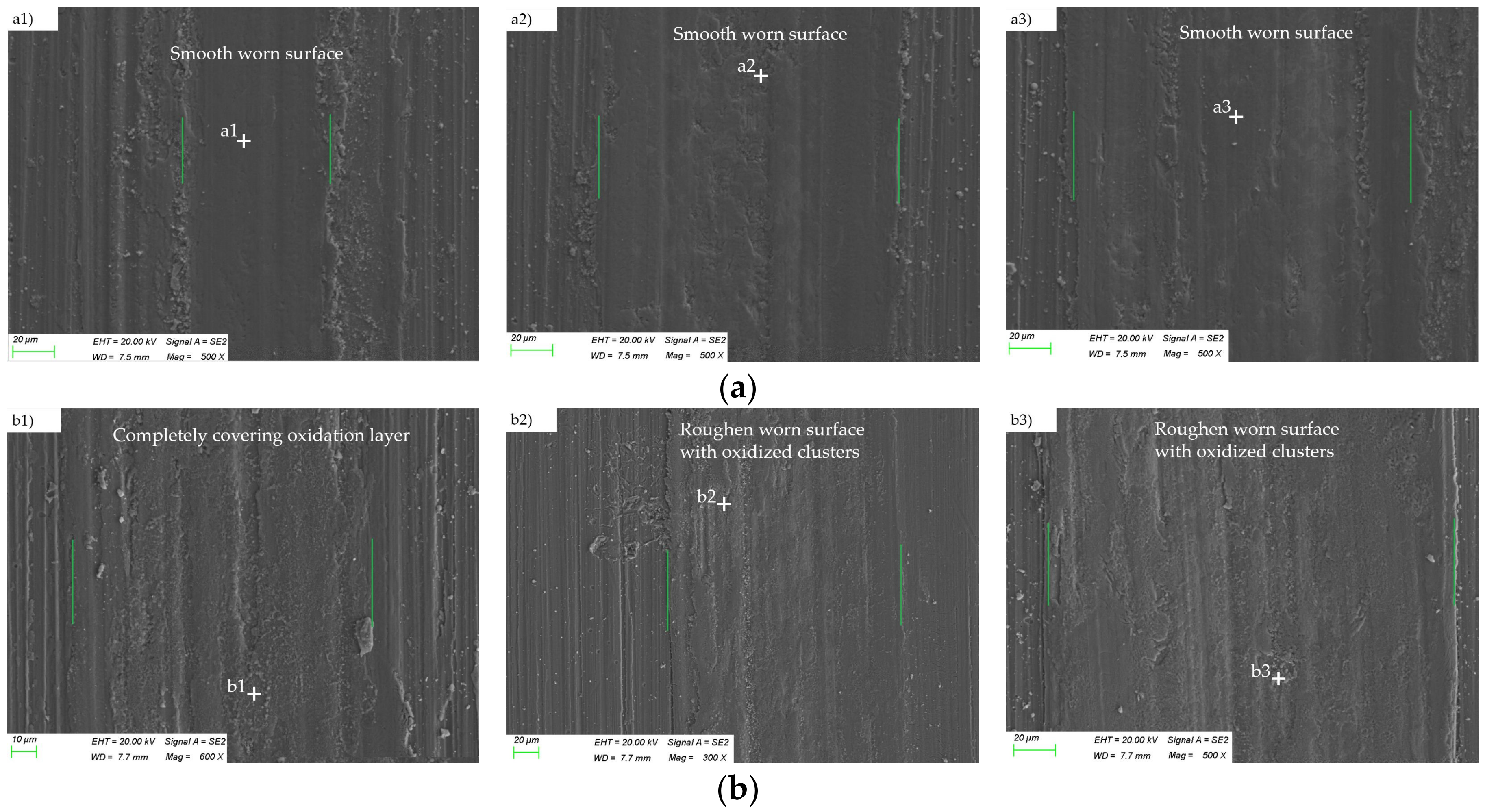

Figure 10.
Morphology of the worn tracks on 2 μm CrN coated M50 disks: (a) at the temperature of 25 °C under the load of (a1) 10 N, (a2) 15 N, and (a3) 25 N; and (b) at the temperature of 200 °C under the load of (b1) 10 N, (b2) 15 N, and (b3) 25 N.
Figure 10.
Morphology of the worn tracks on 2 μm CrN coated M50 disks: (a) at the temperature of 25 °C under the load of (a1) 10 N, (a2) 15 N, and (a3) 25 N; and (b) at the temperature of 200 °C under the load of (b1) 10 N, (b2) 15 N, and (b3) 25 N.
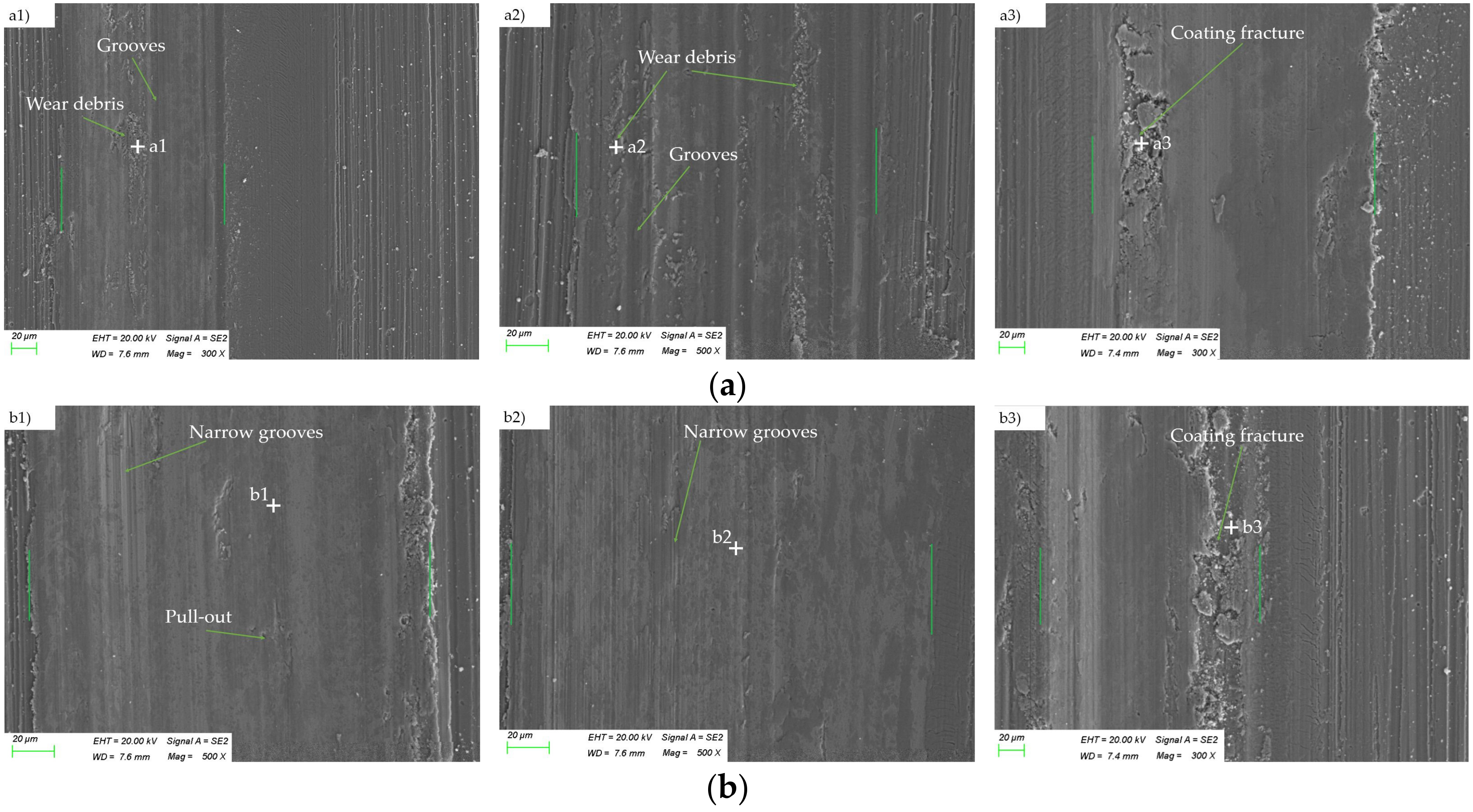
Figure 11.
Morphology of the worn surfaces of 2 μm CrN coated M50 disks: (a) at the temperature of 315 °C under the load of (a1) 10 N, (a2) 15 N, and (a3) 25 N; (b) at the temperature of 400 °C under the load of (b1) 10 N, (b2) 15 N, and (b3) 25 N; and (c) at the temperature of 500 °C under the load of (c1) 10 N, (c2) 15 N, and (c3) 25 N.

Figure 12.
SEM observation of the indented surface of 2 μm CrN coated M50 disks under a load of 15 N and temperature of 500 °C.
Figure 12.
SEM observation of the indented surface of 2 μm CrN coated M50 disks under a load of 15 N and temperature of 500 °C.
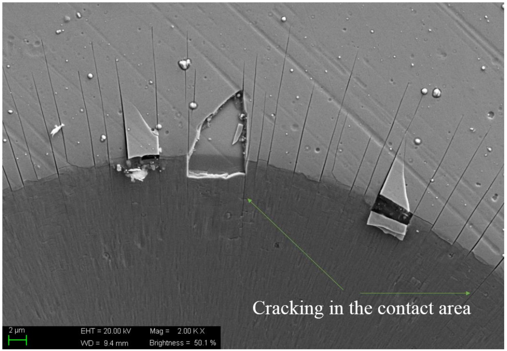
Figure 13.
The schematic drawing of the failure of oxidation film: (a) tensile stress concentration; (b) tensile fracture of oxidation film; (c) shear stress concentration; (d) adhesion occurred after the failure of oxidation film; and (e) verification of the failure mechanisms from the wear scar morphologies of the 2 μm CrN coated M50 disks under the load of 15 N and temperature of 500 °C.


Table 1.
Parameters used in high temperature indentation tests and wear tests.
| Indentation Test | Wear Test | ||
|---|---|---|---|
| Initial contact load | 1 N | Normal load | 10 N, 15 N, 25 N |
| Loading/unloading rate | 2 N/s | Linear speed | 10.5 mm/s |
| Peak load | 300 N | Revs | 900 |
| Holding load | In unloading stage at 30 N | Temperature | 25 °C, 200 °C, 315 °C, 400 °C, 500 °C |
| Holding duration | 60 s | ||
| Temperature | 25 °C, 200 °C, 315 °C, 400 °C, 500 °C | ||
Table 2.
The EDS analysis results corresponding to the positions in Figure 8.
Table 2.
The EDS analysis results corresponding to the positions in Figure 8.
| Element, at.% | Positions | |||||
|---|---|---|---|---|---|---|
| a1 | a2 | a3 | b1 | b2 | b3 | |
| Cr | 40.12 | 42.43 | 36.92 | 44.34 | 46.42 | 35.02 |
| N | 47.68 | 38.06 | 35.21 | 31.8 | 38.68 | 30.14 |
| O | 2.33 | 6.06 | 8.77 | 7.98 | 6.92 | 10.37 |
| Fe | 1.7 | 4.53 | 5.89 | 11.87 | 0.93 | 7.96 |
| W | 5.3 | 7.64 | 14.11 | 5.15 | 6.71 | 16.10 |
Table 3.
The EDS analysis results corresponding to the positions in Figure 9.
Table 3.
The EDS analysis results corresponding to the positions in Figure 9.
| Element, at.% | Positions | ||||||||
|---|---|---|---|---|---|---|---|---|---|
| a1 | a2 | a3 | b1 | b2 | b3 | c1 | c2 | c3 | |
| Cr | 46.39 | 46.23 | 36.6 | 30.19 | 36.2 | 37.99 | 38.36 | 35.08 | 32.35 |
| N | 23.72 | 21.95 | 25.67 | 17.75 | 13.61 | 21.28 | 13.65 | 11.61 | 7.88 |
| O | 22.43 | 25.61 | 30.58 | 37.97 | 44.96 | 38.38 | 41.51 | 44.98 | 51.35 |
| Fe | 4.19 | 5.39 | 6.34 | 12.43 | 3.39 | 2.02 | 3.87 | 6.47 | 5.81 |
| W | 0.07 | 0.04 | 0.05 | – | – | – | – | – | – |
Table 4.
The EDS analysis results corresponding to the positions in Figure 10.
Table 4.
The EDS analysis results corresponding to the positions in Figure 10.
| Element, at.% | Positions | |||||
|---|---|---|---|---|---|---|
| a1 | a2 | a3 | b1 | b2 | b3 | |
| Cr | 48.32 | 42.71 | 34.96 | 31.25 | 36.7 | 12.7 |
| N | 40.27 | 36.84 | 5.49 | 37.53 | 37.93 | 24.65 |
| O | 3.41 | 9.28 | 7.77 | 10.4 | 13.76 | 14.26 |
| Fe | 8.32 | 9.43 | 48.05 | 15.94 | 9.2 | 46.96 |
| W | 4.27 | 2.95 | 0.71 | 3.07 | 2.93 | – |
Table 5.
The EDS analysis results corresponding to the positions in Figure 11.
Table 5.
The EDS analysis results corresponding to the positions in Figure 11.
| Element, at.% | Positions | ||||||||
|---|---|---|---|---|---|---|---|---|---|
| a1 | a2 | a3 | b1 | b2 | b3 | c1 | c2 | c3 | |
| Cr | 37.48 | 32.19 | 17.92 | 32.65 | 21.61 | 4.9 | 23.58 | 18.3 | 4.0 |
| N | 21.93 | 18.67 | 10.45 | 20.97 | 13.72 | 4.53 | 22.68 | 13.85 | 3.47 |
| O | 34.39 | 35.16 | 36.24 | 39.64 | 44.06 | 35.14 | 44.59 | 40.78 | 31.0 |
| Fe | 5.52 | 6.22 | 32.76 | 6.61 | 18.75 | 52.79 | 8.48 | 24.87 | 54.79 |
| W | – | – | 1.9 | – | – | 2.15 | – | – | 3.21 |
Table 6.
Wear transition for CrN coated M50 steel at elevated temperatures and its characteristics.
| Temperatures | Load | |
|---|---|---|
| Below the Load Bearing Limit | Above the Load Bearing Limit | |
| Below 315 °C | Mild-abrasive wear | Coating fracture controlled wear |
| Equal or above 315 °C | Mild-oxidation wear | Compound wear mechanisms containing oxidative wear, coating delamination and adhesive wear |
© 2017 by the authors. Licensee MDPI, Basel, Switzerland. This article is an open access article distributed under the terms and conditions of the Creative Commons Attribution (CC BY) license (http://creativecommons.org/licenses/by/4.0/).
Share and Cite
MDPI and ACS Style
Zhang, C.; Gu, L.; Tang, G.; Mao, Y. Wear Transition of CrN Coated M50 Steel under High Temperature and Heavy Load. Coatings 2017, 7, 202. https://doi.org/10.3390/coatings7110202
AMA Style
Zhang C, Gu L, Tang G, Mao Y. Wear Transition of CrN Coated M50 Steel under High Temperature and Heavy Load. Coatings. 2017; 7(11):202. https://doi.org/10.3390/coatings7110202
Chicago/Turabian StyleZhang, Chi, Le Gu, Guangze Tang, and Yuze Mao. 2017. "Wear Transition of CrN Coated M50 Steel under High Temperature and Heavy Load" Coatings 7, no. 11: 202. https://doi.org/10.3390/coatings7110202
Note that from the first issue of 2016, this journal uses article numbers instead of page numbers. See further details here.