Article

Surface Roughness Reduction of Additive Manufactured Products by Applying a Functional Coating Using Ultrasonic Spray Coating

1
Institute for Materials Research (IMO), Hasselt University, Wetenschapspark 1, B-3590 Diepenbeek, Belgium
2
Flanders Make vzw, Oude Diestersebaan 133, B3920 Lommel, Belgium
3
IMEC vzw, Division IMOMEC, Wetenschapspark 1, B-3590 Diepenbeek, Belgium
*
Author to whom correspondence should be addressed.
Coatings 2017, 7(12), 208; https://doi.org/10.3390/coatings7120208
Submission received: 20 October 2017 / Revised: 14 November 2017 / Accepted: 20 November 2017 / Published: 23 November 2017

Abstract

:
To reduce the high surface roughness of additive manufactured (AM) products, typically a post-treatment is required. Subtractive post-treatments are often performed by hand and are therefore expensive and time consuming, whereas conventional additive post-treatments, such as pneumatic spray coating, require large quantities of coating material. Ultrasonic spray coating, in contrast, is an additive post-treatment technology capable of applying coatings in an efficient way, resulting in less material usage. In this paper, we investigate the application of the ultrasonic spray coating process and the final properties of the coated AM part by applying a thin coating to reduce surface roughness of the AM substrate and to impart hydrophobic functionality. The hydrophobic coating is applied onto flat selective laser sintered (SLS) surfaces prepared from polyamide 12 (PA12) having a surface roughness of Ra = 20 µm. The hydrophobic coating consists of 5 wt % polyvinylidene fluoride (PVDF) in acetone. The coated substrates are analyzed for roughness using a profilometer, a contact angle using a goniometer, and a coating uniformity and thickness using light and scanning electron microscopes. The layer formation applying the ultrasonic spray coating is studied and compared with layer formation using pneumatic spray coating. It is found that a roughness reduction down to 5 µm was achieved via an ultrasonic spray coating with 30 layers of PVDF solution. It is shown in cross-section electron microscopy pictures that, due to the nature of the ultrasonically generated droplets, the rough and porous surface of the SLS surface is filled with the PVDF material after which the roughness is reduced by adding a thin layer on top. In comparison to a standard industry-applied pneumatic spray coating process, the results obtained from ultrasonic spray coating show less material usage, a reduced roughness, and a better filling of the pores, obviously resulting in optimized adhesion.

1. Introduction

Additive manufacturing is a collective term used to describe production processes creating 3D objects by applying the material layer by layer on top of each other. Additive manufacturing processes in general come with several advantages: the production of highly complex geometrical shapes and structures, which might not be possible to be produced using the conventional subtractive methods, and the possibility of using lattice structures inside the object to reduce weight, save material, and lower cost. One of the issues holding back the additive manufacturing processes to be used in mass production is its inherent high surface roughness which is often not suitable for many applications. To circumvent this problem, a post-treatment is generally applied. There are two ways to reduce surface roughness. The first route is subtractive, where the surface roughness is reduced by removing material from the object. The second route is using an additive post-treatment by apply a coating onto the object. Additive post-treatments have several advantages over subtractive post-treatments. Firstly, additive post-treatments do not remove any material from the initial product, meaning mechanical properties are not affected. Secondly, coatings can be applied without direct contact between the coating device and the object, whereas for complex geometries it can be very time-consuming or even impossible to apply a subtractive post-treatment. However, additive post-treatments using current coating technologies apply a high amount of material onto the AM piece such that their dimensions are substantially increased. In addition to this, it is important when using additive post-treatment methods to consider the adhesion of the coating onto the AM surface. In this paper, we investigate the use of an additive post-treatment technology, i.e., an ultrasonic spray coating, to deposit a thin coating on top of an additive manufactured part to reduce surface roughness and impart hydrophobic functionality.
Spray coating is a technology that is mainly used in industry for car body painting or other applications in which thick (100 µm) layers have to be applied on top of a freeform product. The ink is atomized at the nozzle of the spray head generating a continuous flow of droplets. When pneumatic systems are used, the droplets have a broad distribution of diameter due to the application of pressurized air or gas breaking up the ink into droplets. By applying pressurized gas to create the droplets, the kinetic energy of the droplets is also defined in a broad window. This inherently results in droplets fired at the surface without precise control of diameter and speed. For applications where 100 µm thick layers are needed, this is not detrimental as the droplets mainly have diameters below 30 µm. However, when thin coatings have to be applied (below 1 µm), this pressure-based spray coating is not the perfect choice. More advanced spray generation methods are available using directed carrier gasses or electro-spraying [1,2]; however, the kinetic impact of the droplets still influences the spreading of the droplets and thus the final layer quality.
Ultrasonic spray coating (USSC) uses the principle of ultrasonic atomization of the ink. 
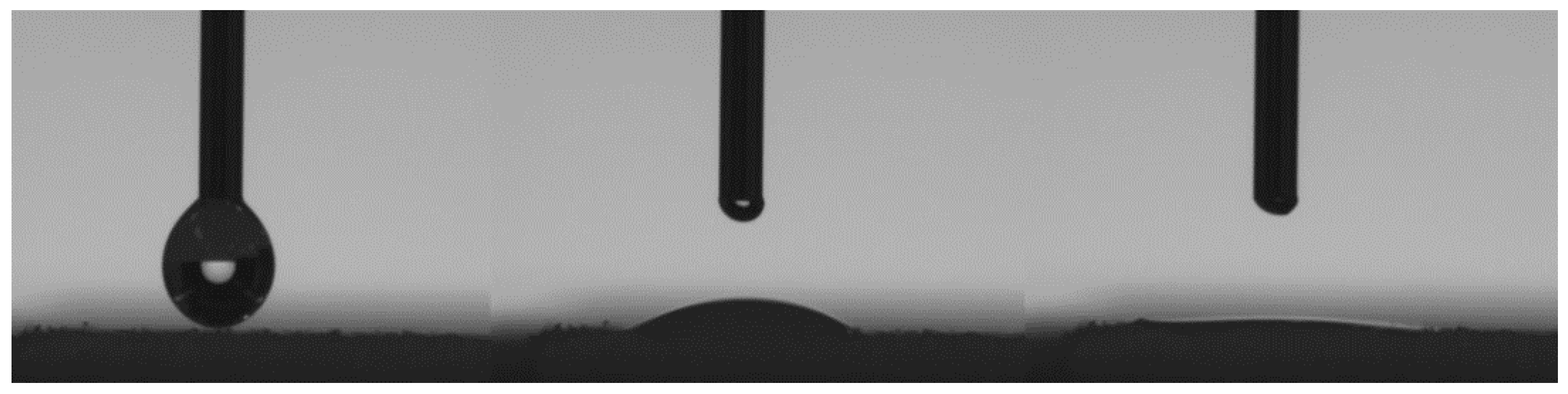
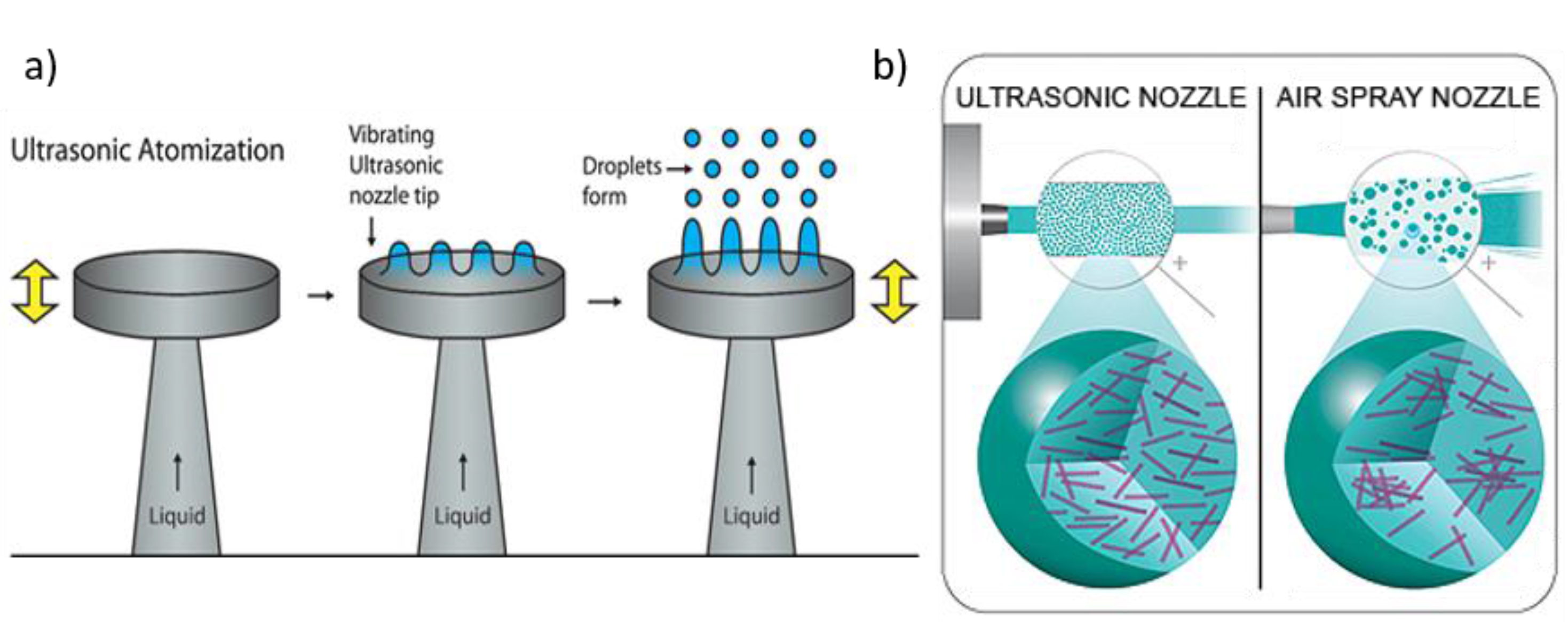
Figure 1a below schematically shows the working principle of ultrasonification, whereas Figure 1b shows the difference in drop formation between pressure-based and ultrasonic spray coating [3].
This ultrasonic atomization of the ink is in contrast to other known spray coating technologies in which the ink is atomized applying only pressure. For USSC, a liquid feed will guide ink to the head where a thin liquid film will form, due to the vibration standing waves will form in the ink film. The tops of these standing waves will detach at sufficient high vibration amplitudes and form small droplets. These droplets are guided to a substrate via a carrier gas, which is additionally used as a shaping gas. The main factor that determines the drop size is the frequency of the ultrasonification and the surface tension and the density of the ink being atomized, with the drop size being inversely proportional to the frequency to the power 2/3.
drop   size ~ f ( 2 3 )
There are several recent articles that have investigated the relationship between drop size and applied frequency upon ink density and surface tension. This results in several formulas to deduce the drop size dependency [4,5,6]. Related to inks being applied within both processes, there are some parameters that can influence the atomization of the liquids depending on the type of liquid. One can divide the inks as follows:
  • Single component inks;
  • True solutions;
  • Mixtures with undissolved particles.
Pure liquids are mainly viscosity limited with a maximum viscosity of about 100 mPa·s. However, this also means that the flow rate will be limited as a result of this higher viscosity. True solutions have limits similar to those of the pure liquids, but with a possible point of attention when high molecular weight polymer chains are dissolved. These polymer chains can induce high extensional viscosities and stabilize filaments between droplets and thus limit droplet formation. Mixtures with undissolved solids are limited by particle size, the concentration of the solids, and the interaction between the solids and the carrier. Particle size is critical; if the particle is larger than one-tenth of the median drop size, the mixture will not atomize properly. The maximum flow rate is mainly limited by the oscillation frequency and the atomization area of the nozzle.
The ultrasonic spray coating system has been applied in recent research for many different applications and functional materials. In one article [7], a mixture of SiC (80 or 800 nm particles) and ethanol was prepared to study the suspension and spraying parameters. The biggest difference between suspensions with either 80 or 800 nm particles will be in their density and surface tension. Further, the authors concluded that up to 16 wt % SiC in aqueous suspension only resulted in a drop size variation of about 1 micrometer. However, the cluster size and morphology were affected by two main factors: the kinetic energy of the droplet and the evaporation behavior of the droplet. Other process optimization work was performed as described in an article by Bose et al. [8]. In this study, they tried to deduce the important parameters for ultrasonic spraying coating while maintaining the ink and changing the effective spray parameters. They were able to deduce three distinct regions: wet, dry, and just wet. In the wet regime, the formation of edge peaks (at the edges of the shadow mask) was observed. In the dry regime, these peaks did not show up, but the resulting film had a fairly high roughness. The third regime, just wet, was the regime that combined the low roughness of the wet regime and the limited formation of the edge peaks due to the shadow mask. This just wet regime was important for the eventual film formation and depended heavily on the used solvents. This does mean that, for each different ink, the spray height and hotplate temperature will need to be tuned. Several articles have been dedicated to the droplet’s impact and behavior once the droplet hits the substrate. In one article [9], the authors describe a model for the drying time of droplets (from ultrasonic spray coating) on a substrate and experimentally link this drying time to the film’s morphology. Interestingly, the authors do not include any information on the wetting behavior of the ink on the substrate. The results look promising but need additional validation for different ink systems. In another work [10], the authors describe the effect of spray parameters on the morphology of spray coating a solution of P3HT:PCBM (poly(3-hexathiophine-2,5-diyl) (P3HT), [6,6]-Phenyl C61 butyric acid methyl ester (PCBM)) in ODCB (1,2-dichlorobenzene). They noticed that films deposited by spray coating had a fairly high roughness. Additionally, they deduced that the pressure of the carrier gas has a profound effect on droplet collision and coalescence for low pressures, while high pressures resulted in turbulence and, as a result, collision and coalescence. Applications achieved with ultrasonic spray coating of functional materials have been shown in recent work. Graphene flakes [11] in a DMF/ethanol solution, polystyrene nanoparticles from water–ethanol [12] and PEDOT:PSS (poly(3,4-ethylenedioxythiophene) polystyrene sulfonate) [13] are deposited using ultrasonic spray coating for their application in organic photovoltaic or layer formation studies.
The USSC system has, to the best of the authors’ knowledge, never been used to coat 3D parts to reduce roughness or add functional coatings. Therefore, in this work, the deposition of a functional ink is applied on flat additive manufactured substrates to study how the parameters of the USSC system can be adapted to reduce roughness and add functional coatings, which, in future work, can be applied on 3D Additive Manufactured (AM) pieces. How ink formulation and the ultrasonic spray coat parameters influence the flow behavior on the substrate is studied. The aim of this research is to optimize the kinetics of the droplets after atomization in such a way that the ink will flow into the valleys of the rough AM substrate, preventing the coverage of the top region of this same substrate. This way, the roughness is drastically reduced without the need to overcoat the sample with too much material. Finally, a thin top-coating can be applied to end up with a fully closed coating—also covering the top regions—having a very low roughness, less material usage, and a predicted adhesion improvement. To state this, the ultrasonic spray coating technology is compared to the pressurized spray coating technology showing the optimized coating formation. The choice of ink is not only based on its rheological properties but also on its final functional properties. Polyvinylidene fluoride (PVDF) as a material is chosen for its hydrophobic properties, as will be shown further in the results section of this paper. Finally, it should be noted that this work has been performed with flat AM substrates. Once the transition to 3D AM pieces will be made, the influence of the nozzle height and other parameters were carefully reviewed to exclude any influence of these USSC parameters on the final result. However, the USSC system is equipped with a robotic arm that can turn and twist such that for 3D pieces the nozzle distance can be kept the same when moving over the 3D piece and the direction of the droplets towards the substrate is always perpendicular.

2. Materials and Methods

2.1. Substrates

A flat tile, selective laser sintered (SLS) from nylon 12 (PA-12; ρ (25 °C) = 1000 kg/m3, Tglass = 37–43 °C) was used as substrate. The substrates were obtained from Materialise NV (Leuven, Belgium) as flat tiles (20 mm × 20 mm × 1 mm) and they did not undergo any form of post-treatment except for excessive loose grain removal by brushing or air blowing. The following cleaning procedure was applied before spray coating using an ultrasonic bath:
  • Soap water for 15 min to remove grease,
  • H2O for 15 min, twice, to remove soap,
  • Acetone for 15 min,
  • Isopropyl alcohol for 15 min.
When the cleaning process was completed, the substrates were air-dried.

2.2. Coating Material

The hydrophobic coating consisting of a certain wt % polyvinylidene fluoride (PVDF) (ρ (25 °C) = 127 kg/mol, Tmelt = 160 °C) dissolved in acetone with concentrations of 1–10 wt % was tested. The coating was prepared by dissolving PVDF in acetone under stirring at 80 °C for 15 min. This resulted in a coating solution with a viscosity of 3 mPa·s at 25 °C (measured using an AR G2, stress controlled rheometer from TA Instruments, New Castle, DE, USA). After applying the coating, thermal curing, in a box oven at 175 °C for 15 min, was carried out to ensure proper adhesion onto the substrate. Thermal curing below 175 °C for 10 min resulted in a lower mobility of the PVDF containing droplets, preventing flow of the PVDF into the pores of the SLS substrate. Initial testing with profilometry (Dektak XT from Bruker, Billerica, MA, USA) and scanning electron microscopy (FEG-SEM, Thermo Fisher Scientific, Waltham, MA, USA) showed that the curing process has no visible influence on the roughness of the substrates themselves due to a full covering of the substrate and a high heat absorption by the coating.

2.3. Coating Process

The coating was applied using ultrasonic spray coating. An Exactacoat Ultrasonic Coating System from Sono-Tek (Milton, NY, USA) equipped with an Impact EDGE ultrasonic spraying nozzle was used for the experiments in this article. This nozzle allows a spraying width up to 15 cm and the Impact EDGE system maintains precise control of the coating at the required flow rate. Several parameters of the ultrasonic spray coating process are optimized in order to achieve the best result in terms of the amount of deposited material, the final roughness, the layer thickness, and the flow behavior of the ink onto the AM substrate. The parameters that are altered for the ultrasonic spray coating process are as follows:
  • The height between nozzle and substrate (from 5 to 7 cm in steps of 1 cm);
  • The amount of sprayed ink in function of time (from 1.5 to 2 mL/min in steps of 0.1 mL/min);
  • The applied power for the atomization (from 1.0 to 3.0 W in steps of 0.5 W);
  • The amount of spray passes (from 1 to 30 passes in steps of 1 spray pass).
Further, the speed of the spray nozzle (10 mm/s), the temperature of the substrate table (30 °C), and the overpressure of the carrier gas (0.13 bar) were fixed throughout all experiments.

2.4 Analysis

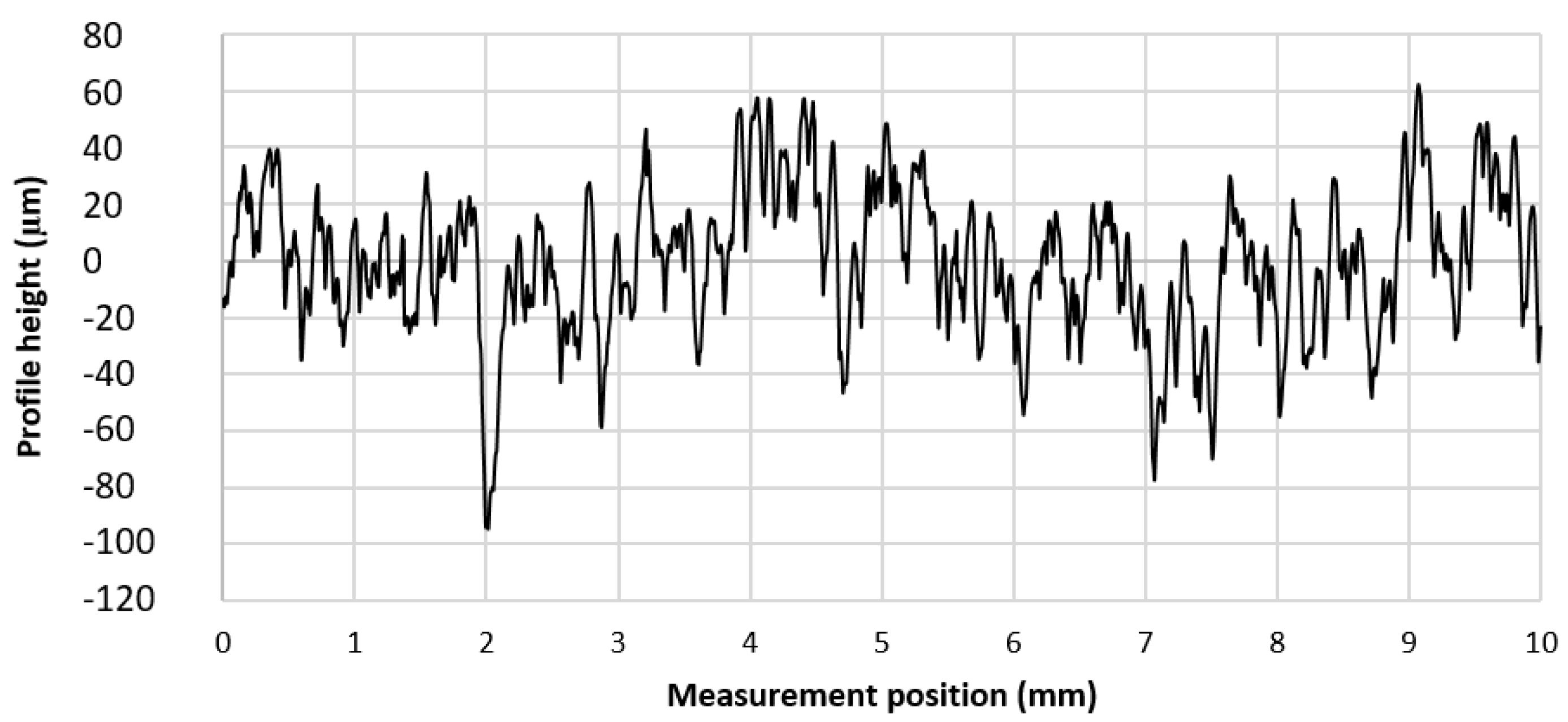
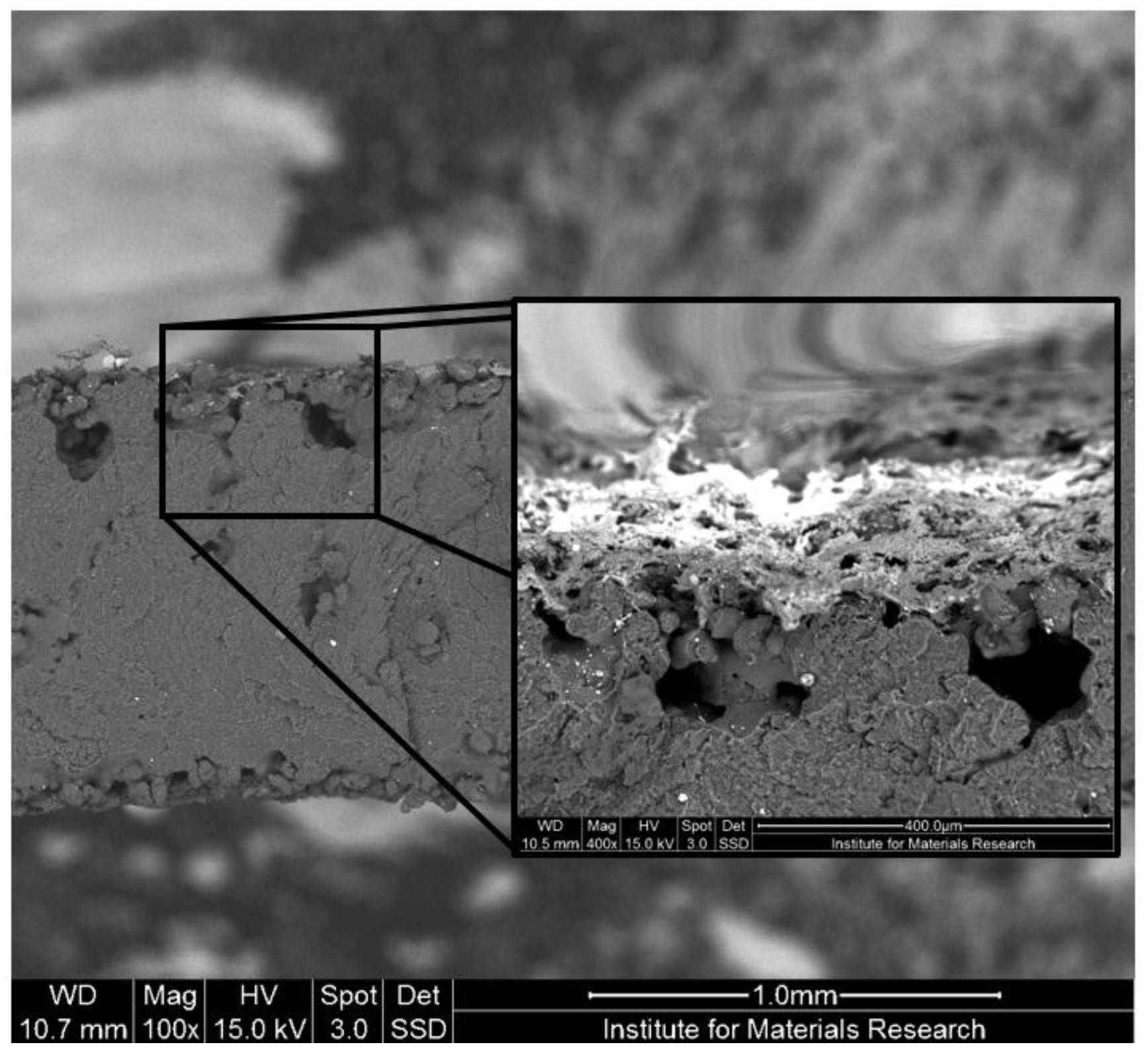
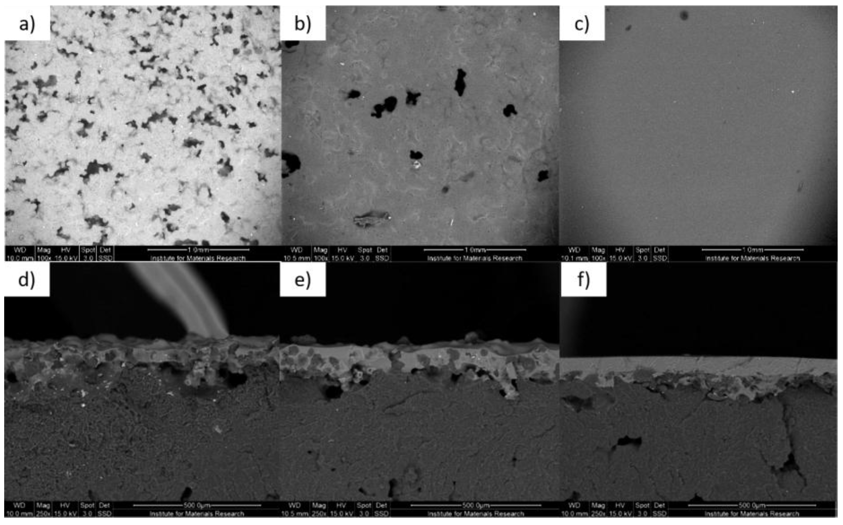
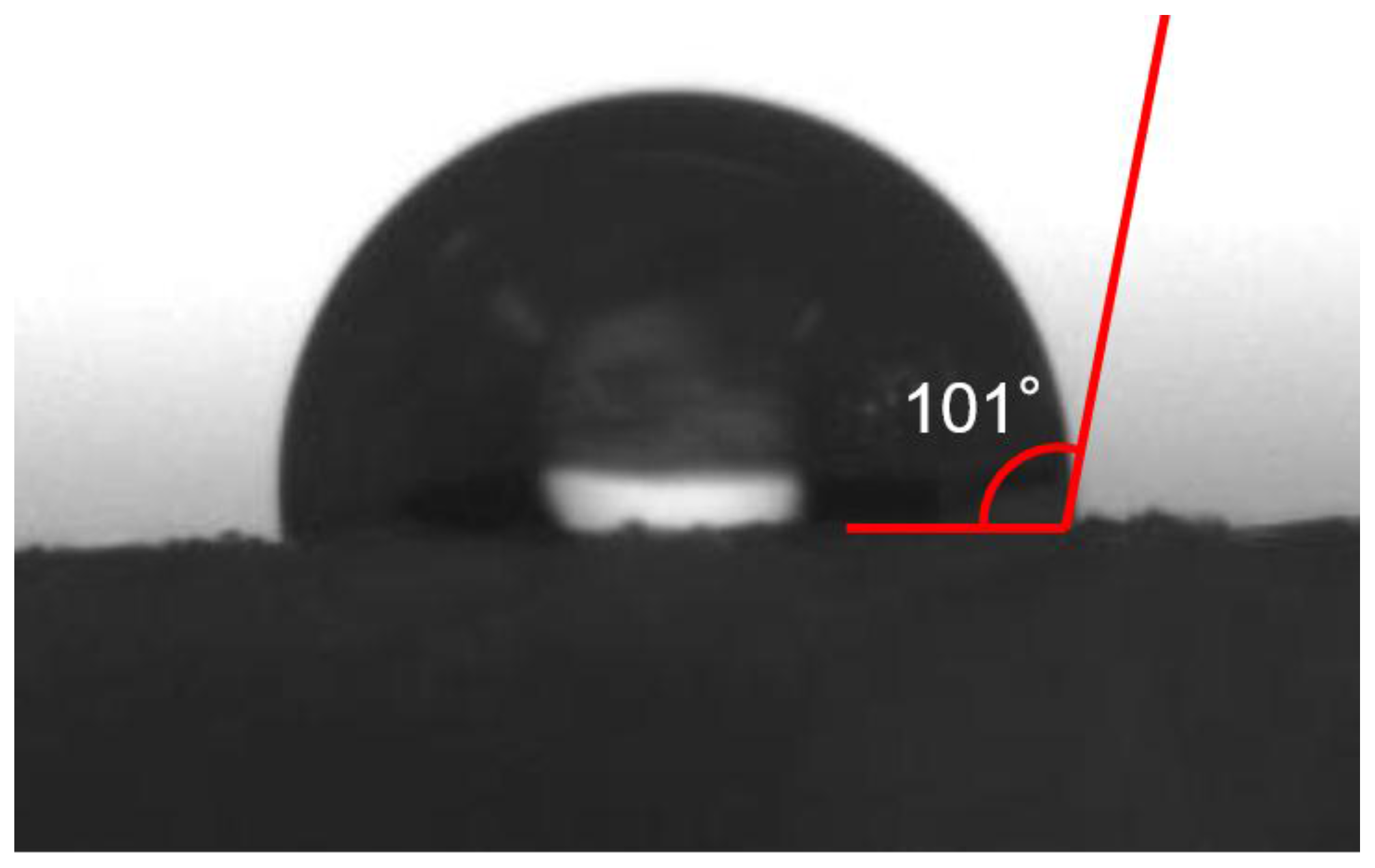
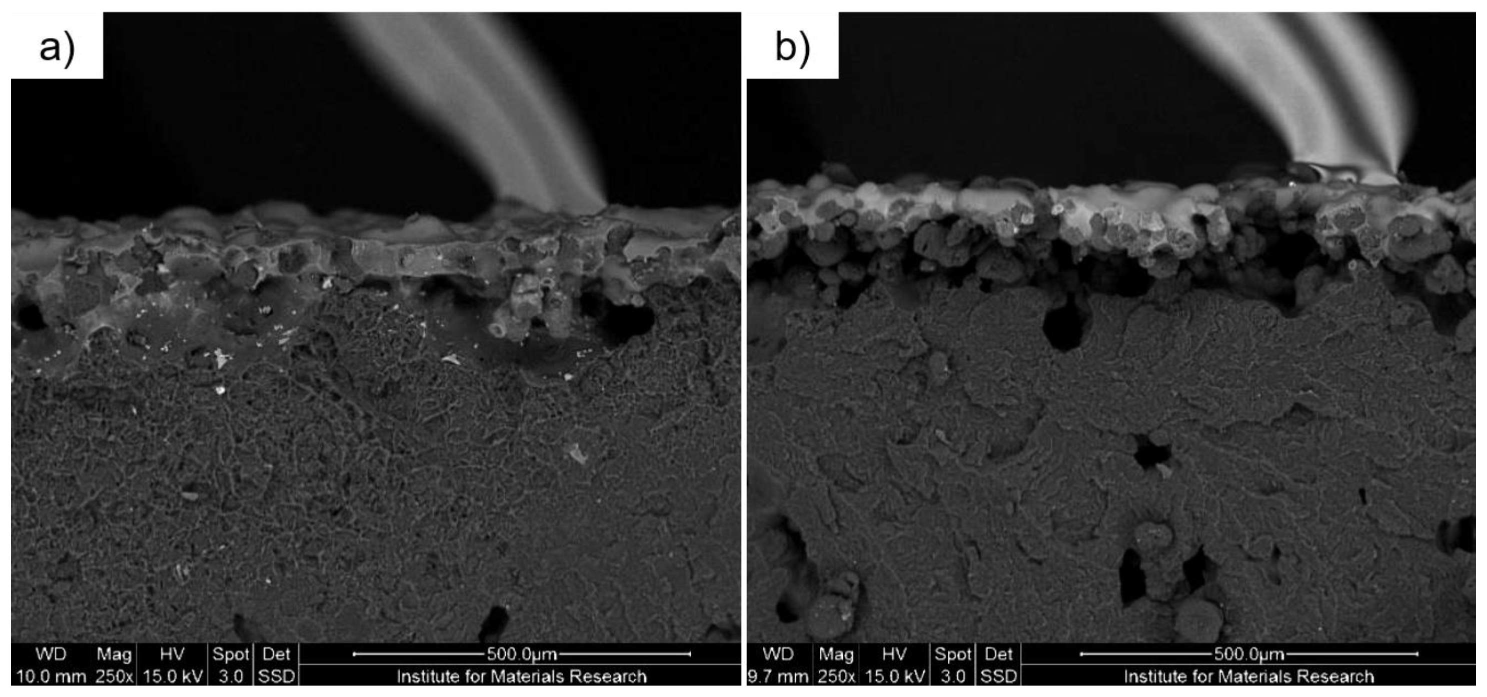
After applying the coating onto the substrate, the surface was analyzed with an Axiovert 40 MAT optical microscope (Carl Zeiss, Oberkochen, Germany) to acquire qualitative information on the coverage and flow behavior of the coating material. The surface roughness was measured with a profilometer (Dektak XT from Bruker, Billerica, MA, USA) and the hydrophobicity of the coated substrates was inferred by performing contact angle measurement with an OCA 15plus system from Data Physics (San Jose, CA, USA). To obtain coating thickness and surface uniformity, the samples were imaged using an FEI Quanta 200F Field Emission Gun Scanning Electron Microscope (FEG-SEM, Thermo Fisher Scientific, Waltham, MA, USA) in back-scattered electron (BSE) mode for an optimized z-contrast.

3. Results

3.1. Substrates

The surface of the original substrates has a roughness of Ra = 20 μm, whereas the peak-to-peak value is measured as Rt = 150 μm. An example of a profilometry measurement for an SLS substrate used in this work is shown in Figure 2. The surface roughness of these 3D printed SLS substrates is due to the PA-12 particles and the additive manufacturing process.

3.2. Wetting

The wetting behavior of the coating ink onto the substrate was analyzed by applying a droplet of ink onto the substrate. Due to the low viscosity and good wetting properties, the PVDF ink completely wets the 3D printed PA-12 substrate (see Figure 3). This behavior implies a very efficient usage of the coating material to reduce the surface roughness. Ideally, the ink will flow into the pores of the surface before the solvent evaporates without being pinned onto the top rough parts of the SLS substrate.

3.3. Optimal Parameters

Preliminary tests were conducted to optimize different parameters of the ultrasonic spray coating process. It was concluded that 5 wt % PVDF in acetone was the optimal composition. A lower loading led to a higher amount of coating layers to be deposited, increasing the processing time. A higher loading led to drying of the ink during deposition and a subsequent coating of the top parts of the rough surface. The influence of the different ultrasonic spray coating parameters were evaluated for the PVDF ink, and the final concluded optimal parameters are shown in Table 1. However, when we look at the variation in the parameters as described in Section 2.3, important conclusions can be drawn. When the nozzle height was too low, the droplets were still too wet, resulting in a higher mobility and therefore a non-uniform coating. For nozzle heights that were too high, the solvent evaporated nearly completely during flight, resulting in a dry PVDF coating on top of the SLS substrates, so no penetration of the PVDF into the pores of the substrate was possible. The same argument can be made for the applied power for the atomization. Lower levels of power that were too low resulted in a lower kinetic energy of the droplets, so the coating was too wet, resulting in a non-uniform coating. If kinetic energy was too high, there was little or no penetration of PVDF into the pores of the substrate. Further, it was noticed that a low amount of spayed ink as a function of time meant that too many spray passes were needed for full coverage, so this last parameter was coupled with the amount of spray passes. It was found that, for 1.9 mL/min, up to 30 spray passes were needed for full coverage. This was then set as the optimized parameters.
Next, we focused on the optimal amount of coating layers. The coating parameters shown in Table 1 were applied whilst applying 10, 20, and 30 layers. The results were repeated several times, yielding the average results shown in Table 2.
Applying 30 layers of PVDF coating shows a drastic roughness reduction in comparison to applying only 10 or 20 layers. This is explained by the fact that, for the first 20 layers, the pores of the AM SLS substrate were filled, resulting in no—or little—change in surface roughness. This especially is visible in the Rt values and to a lesser extent in the Ra values. Once the pores were filled, the material started to build up from the valleys of the rough surface towards the top, drastically decreasing the surface roughness from approximately 12 µm down to 5 µm. In the last column of Table 2, the amount of sprayed material was calculated from an ultrasonic spray coating process on glass. The layer thickness directly expresses the amount of material deposited; for the deposition on glass, a smooth layer was achieved. It is clear that doubling the amount of passes in turn doubles—within a limited error margin—the amount of sprayed material.
As discussed above, by applying more than 20 layers, the porous structure of the SLS substrates is covered. Any additional amount of coating material will end up covering and smoothing the surface of the substrate. This transition of pore filling to smooth surface covering was visualized using a scanning electron microscope, images from which are shown in Figure 4. The dark spots on the images represent gaps in the PVDF coating. After a 10-layer coating was applied, some spots remain uncoated due to the material’s flowing into the pores. This results in a negligible roughness reduction, shown in Figure 4a. The 20-layer coating shows much improvement over 10 layers, but it is still not optimal, as can be seen in Figure 4b. Further increasing the coating layers to 30 yielded a smooth uniform coating, as can be seen in Figure 4c. Cross-section images of the coated substrates for the same amount of spray passes are shown in Figure 4d–f and confirm this behavior.

3.4. Hydrophobicity

As the coating consisted of PVDF and acetone, the fluorine molecules in the polymer imparted a hydrophobic property to the AM SLS partly due to the low surface free energy of PVDF, as shown in Figure 5. The resulting contact angle of water after coating with PVDF was 101°, showing the hydrophobic behavior of the applied coating. To show that this indeed acts as a hydrophobic coating on top of the roughness reduction, the contact angle of the initial uncoated sample was also measured. The contact angle was measured as 114°. For the samples that still have a rough surface, the contact angle was measured between 110° and 116°. For the USSC sample with 10 passes, the contact angle was 110°. For the sample with 20 passes, the contact angle was 116°. For the pneumatic spray coated sample, a contact angle of 113° was measured. These higher contact angles were expected, since, for rough samples with sharp peaks, water droplets are pinned at the surface and therefore achieve these higher contact angles. Further, in literature, it has been shown that a smooth PA12 sample exhibits a contact angle starting from 60° [14]. This was also tested for our SLS substrates. A substrate was first smoothened using sand paper to a final roughness of 6.1 µm. By applying this subtractive smoothing technique, the sharp peaks were leveled out and droplet pinning at the surface stopped. A contact angle of 81° was measured. This clearly indicates that the PVDC layer applied by USSC after 30 passes not only smoothens the surface by pore filling but also adds a hydrophobic coating with a contact angle that changes from a value from 60° (for smooth PA12) or 81° (for a smoothened substrate applying sandpaper treatments) to 101°.

3.5. Comparison with Pneumatic Spray Coating

A comparison was made with the pneumatic spray coating process because of the similarity between both processes. The same coating ink (5 wt % PVDF-acetone) was used in a pneumatic spray coater with three different parameter combinations, as shown in Table 3. The optimization of the pneumatic spray coating and the parameters mentioned in Table 3 are obtained after a preliminary parameter study. The spray opening diameter was changed from 1.0 to 2.0 mm in steps of 0.1 mm, and the pressure was kept constant at an overpressure of 0.6 bar. This last value, 0.6 bar, corresponds to 8.7 psi. It is clear that the applied pressure for pneumatic spray coating was 4–5 times higher than that for ultrasonic spray coating, where the overpressure was 0.13 bar (2.0 psi).
First, it should be mentioned that fewer coating passes were needed for the pressurized spray coating, as more material was deposited per pass. It should also be noted that a huge difference in process adjustability considering the different number of variable parameters was found as compared to the ultrasonic spray coating process as shown in Table 4. The surface roughness results combined with the layer thickness for each parameter combination are shown in Table 4.
These results show Ra values before and after the PVDF coating was cured. Note that results before thermal curing are not mentioned, as the curing step is necessary to ensure proper adhesion. Tests showed that the thermal curing had no influence on the surface roughness in the ultrasonic spray coating process, meaning its only purpose was ensuring the durability of the applied coating. The results shown in Table 4 on the other hand show a drastic change in surface roughness before and after curing (∆Ra). Eventually, neither one of the parameter sets shows a notable roughness reduction post-curing. Within these results lies the key principle to clarify the success of the ultrasonic spray coating results opposed to the pneumatic spray coating process. Figure 6 shows a cross-section image of a pneumatic spray coated substrate before thermal curing.
The image shows a rough PVDF layer resting on top of the original substrate. The coating material itself laying on top of the substrate makes the surface roughness measurement return promising results. When curing the coating, the PVDF will not flow into the pores of the surface but stays on top of the original surface and even—by curing—takes the shape of the initial surface. Therefore, the roughness before curing, compared to after curing, is lower (as the layer is still in the wet regime and thus much smoother) and when the PVDF coating is drying, it goes along with the surface roughness before coating.
In Figure 7a, the cross-sectional picture for an ultrasonic spray coated sample with 30 spray passes is shown. From this picture, the above-mentioned results and hypothesis on pore filling and surface reduction is proven when it is compared to the cross-sectional picture in Figure 7b of the pressurized spray coating. It is clear from this image that the coating does not properly flow into the pores and lies on top of the surface following the original surface profile. The coating material stacked on top of the peaks of the surface is wasted and adds to the roughness, and the pores are not filled properly. This is also detrimental to the adhesion between the coating and the substrate.

4. Discussion and Conclusions

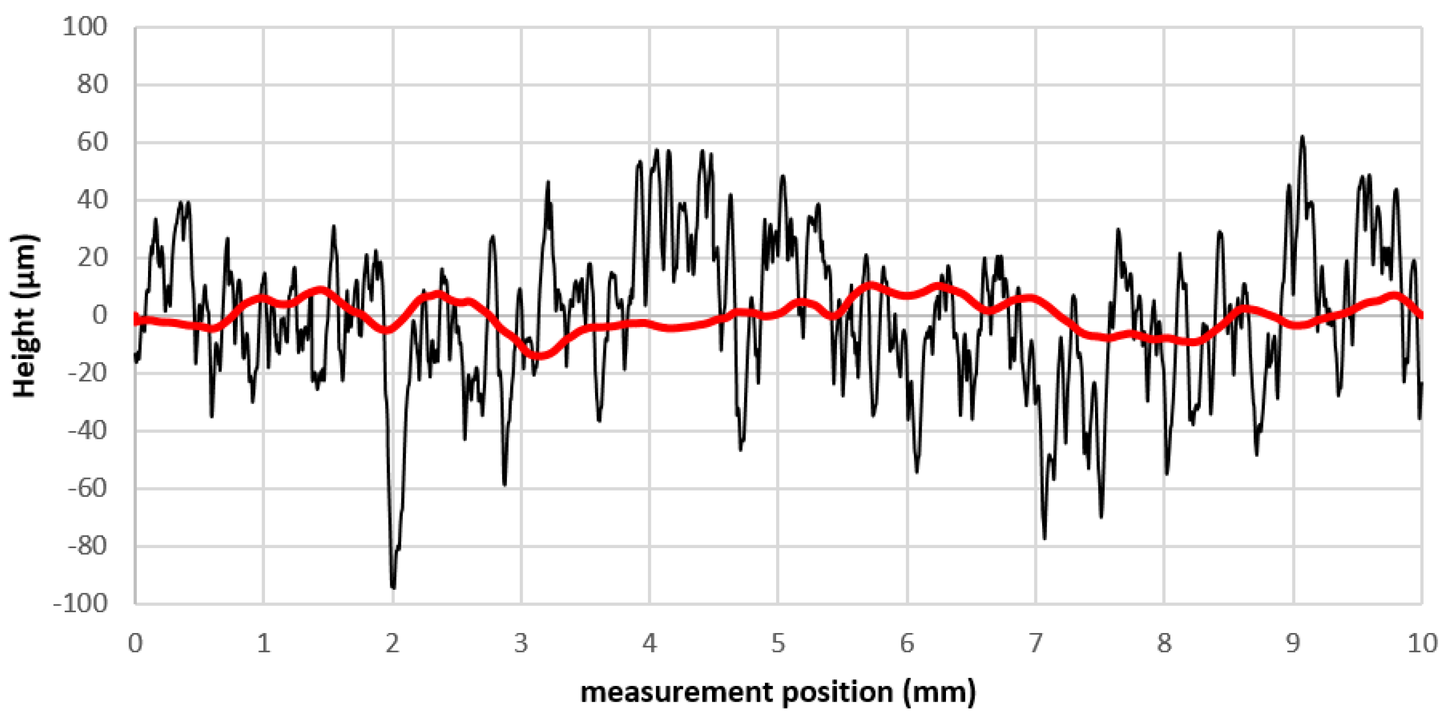
In this article, the possibilities of ultrasonic spray coating for surface roughness reduction on additive manufactured pieces are explored. It is shown here that a roughness reduction below 5 µm can be achieved solely by process optimization. Promising results, as shown in Figure 8, confirm the added value of this process, increasing the potential of the additive manufacturing field.
The ultrasonic spray coating process is capable of precisely applying coating in a controlled manner such that the ink reaches the surface while still wet. This means that the ink can flow into the pores because of its low viscosity and surface tension. The solvent evaporates, leaving the active material in the pores that will gradually fill up the pores. In the pneumatic spray coating process, the spray conditions cannot be controlled as precisely as they can in ultrasonic spray coating conditions, which causes a large amount of sprayed material to sit on top of the rough surface without penetrating the pores. Additionally, the solvent evaporates the coating and cannot flow properly after arriving on the substrate surface, causing the active material to sit on top of it. We can conclude therefore that ultrasonic spray coating has the following advantages over conventional pneumatic spray coating:
  • A higher roughness reduction is achieved without adding material on top of the SLS substrate. To achieve the same roughness reduction as in the USSC, a thicker coating using PS was necessary due to the non-existing pore filling; therefore, a higher amount of coating material is likely needed for the same smoothing process.
  • The material deposited by ultrasonic spray coating can more easily penetrate the porous surface structure of the additive manufactured piece. This is explained by the fact that the ink droplets, created by the ultrasonic vibrations, have nearly no kinetic energy when created at the spray nozzle. It is the carrier gas that, by applying a specific pressure, focuses the droplets towards the substrate with a tunable kinetic energy/speed. For a low kinetic energy, the droplets arrive with low speed at the porous surface and the polymer deposited can more easily find, due to capillary forces, its way inside the pores. For the pneumatic spray coating, the kinetic energy of the droplets, fired at the surface, is so large that penetration is more difficult and the polymer is deposited on top of the surface without penetrating. It is believed that, due to this difference in the flow behavior of the polymer in and on the surface, the adhesion of the ultrasonically sprayed coatings, compared to that of pneumatically sprayed coatings, is better.
To achieve a further and more efficient roughness reduction, a combination of three distinct aspects, namely, process optimization, ink optimization, and substrate preparation is needed. By doing so, an even better penetration of the ink inside the pores can be achieved. When the substrate is pre-treated, a different wetting behavior between the valleys and the top of the rough surface can be achieved, leading to better flow of the ink inside the valleys. Further work will involve ink optimization to achieve different kinetics of the polymer-solvent blend when reaching the surface such that the mobility of the ink on the surface is enhanced.

Acknowledgments

The authors would like to thank the support of Flanders Make vzw for partial funding of the ultrasonic spray coating installation.

Author Contributions

Wim Deferme and Jeroen Drijkoningen conceived and designed the experiments. Sam Slegers and Mathias Linzas performed the experiments and analyzed the data. Jan D’Haen contributed to analysis by SEM. Jeroen Drijkoningen, Naveen Krishna Reddy, and Wim Deferme analyzed the results. Sam Slegers and and Mathias Linzas wrote the article. The original idea for the study and major endorsement came from Wim Deferme.

Conflicts of Interest

The authors declare no conflict of interest.

References

  1. Steirer, K.X.; Reese, M.O.; Rupert, B.L.; Kopidakis, N.; Olson, D.C.; Collins, R.T.; Ginley, D.S. Ultrasonic spray deposition for production of organic solar cells. Sol. Energy Mater. Sol. Cells 2009, 93, 447–453. [Google Scholar] [CrossRef]
  2. Zhao, X.; Lojewski, B.; Yang, W.; Zhu, T.; Mi, B.; Gao, Z.; Huang, W.; Deng, W. Electrospray as a Fabrication Tool in Organic Photovoltaics. Rev. Nanosci. Nanotechnol. 2012, 1, 172–186. [Google Scholar] [CrossRef]
  3. Nanotechnology Coatings Deposited Using Ultrasonic Spray. Available online: http://www.sonotek.com/nanotechnology-overview/ (accessed on 28 August 2017).
  4. Rajan, R.; Pandit, A.B. Correlations to predict droplet size in ultrasonic atomization. Ultrasonics 2001, 39, 235–255. [Google Scholar] [CrossRef]
  5. Yasuda, K.; Badno, Y.; Yamaguchi, S.; Nakamura, M.; Oda, A.; Kawase, Y. Analysis of concentration characteristics in ultrasonic atomization by droplet diameter distribution. Ultrason. Sonochem. 2005, 12, 37–41. [Google Scholar] [CrossRef] [PubMed]
  6. Kim, J.; Kim, K.; Ha, K.; Kim, M. Numerical analysis for the optimum condition of ultrasonic nebulizing. Jpn. J. Appl. Phys. 2016, 55, 07KE03. [Google Scholar] [CrossRef]
  7. Bastwros, M.; Kim, G. Ultrasonic spray deposition of SiC nanoparticles for laminate metal composite fabrication. Powder Technol. 2015, 288, 279–285. [Google Scholar] [CrossRef]
  8. Bose, S.; Keller, S.S.; Alstrøm, T.S.; Boisen, A.; Almdal, K. Process optimization of ultrasonic spray coating of polymer films. Langmuir 2013, 29, 6911–6919. [Google Scholar] [CrossRef] [PubMed]
  9. Lonakar, G.S.; Mahajan, M.S.; Ghosh, S.S.; Sali, J.V. Modeling thin film formation by Ultrasonic Spray method: A case of PEDOT:PSS thin films. Org. Electron. 2012, 13, 2575–2581. [Google Scholar] [CrossRef]
  10. Xie, Y.; Gao, S.; Eslamian, M. Fundamental Study on the Effect of Spray Parameters on Characteristics of P3HT:PCBM Active Layers Made by Spray Coating. Coatings 2015, 5, 488–510. [Google Scholar] [CrossRef]
  11. Modesto-López, L.B.; Miettinen, M.; Torvela, T.; Lähde, A.; Jokiniemi, J. Direct deposition of graphene nanomaterial films on polymer-coated glass by ultrasonic spraying. Thin Solid Films 2015, 578, 45–52. [Google Scholar] [CrossRef]
  12. Stryckers, J.; D’Olieslager, L.; Silvano, J.V.M.; Apolinario, C.K.; Laranjeiro, A.C.G.; Gruber, J.; D’Haen, J.; Manca, J.V.; Ethirajan, A.; Deferme, W. Layer formation and morphology of ultrasonic spray coated polystyrene nanoparticle layers. Phys. Status Solidi 2016, 6, 1–6. [Google Scholar] [CrossRef]
  13. Liu, S.; Zhang, X.; Zhang, L.; Xie, W. Ultrasonic spray coating polymer and small molecular organic film for organic light-emitting devices. Sci. Rep. 2016, 6, 37042. [Google Scholar] [CrossRef] [PubMed]
  14. Extrand, C.W. Contact Angles and Their Hysteresis as a Measure of Liquid-Solid Adhesion. Langmuir 2004, 20, 4017–4021. [Google Scholar] [CrossRef] [PubMed]
Figure 1. (a) The process of ultrasonic atomization of the coating ink at the spray nozzle; (b) Comparison of droplet size and active material distribution between ultrasonic spray coating and pneumatic spray coating [3]. Copyright 2017 Sono-Tek.
Coatings 07 00208 g001
Figure 2. Profilometry measurement of an untreated selective laser sintered (SLS) substrate.
Coatings 07 00208 g002
Figure 3. Wetting behavior of the polyvinylidene fluoride (PVDF)–acetone solution onto a nylon 12 SLS sample.
Coatings 07 00208 g003
Figure 4. (ac) Scanning electron microscope surface images of a 10, 20, and 30-layer PVDF coating on SLS substrates, respectively, in BSE mode; (df) Scanning electron microscope cross-section images of a 10, 20, and 30-layer PVDF coating on SLS substrates, respectively, also in BSE mode.
Coatings 07 00208 g004
Figure 5. Contact angle made by water on a PVDF-coated flat SLS substrate.
Coatings 07 00208 g005
Figure 6. Scanning electron microscope cross-sectional image of a PVDF-coated SLS substrate by pneumatic spray coating.
Coatings 07 00208 g006
Figure 7. Scanning electron microscope cross-sectional images of a PVDF-coated SLS substrate applied by (a) ultrasonic spray coating and (b) pneumatic spray coating.
Coatings 07 00208 g007
Figure 8. Surface roughness profile of an untreated SLS sample compared to the result of applying a 30-layer PVDF coating by ultrasonic spray coating.
Coatings 07 00208 g008
Table 1. Optimal parameters for the ultrasonic spray coating process whilst applying 10 layers of PVDF coating on SLS substrates.
ParametersOptimal Value
Ink (wt %)5
Volume flow (mL/min)1.9
Nozzle speed (mm/s)10
Nozzle frequency (kHz)120
Power (W)2.5
Pressure (bar)0.13
Hotplate temperature (°C)30
Spraying height (cm)6
Ra (µm)15.1
Rt (µm)117.9
Table 2. Roughness results for the initial substrate before coating and after applying 10, 20, and 30 layers of coating.
# LayersRa (µm)Rt (µm)Layer Thickness (µm)
0201500
1015.1117.925.1
2011.9112.342.3
304.830.173
Table 3. Parameter combinations for the pneumatic spray coating process.
Parameters123
# Layers325
Spray opening diameter (mm)1.01.61.6
Pressure (bar)0.60.60.6
Table 4. Pneumatic spray coating results, PVDF coating on SLS substrates.
Parameters123
Layer thickness (µm)24.612.624.2
Ra (µm) pre-curing11.815.914.8
Ra (µm) post-curing18.420.219.6
Ra (%)35.721.424.3

