
Graphene Coating on Copper by Electrophoretic Deposition for Corrosion Prevention

Colloids and Materials Chemistry Department, CSIR—Institute of Minerals and Materials Technology, Bhubaneshwar 751013, India
*
Author to whom correspondence should be addressed.
Coatings 2017, 7(12), 214; https://doi.org/10.3390/coatings7120214
Submission received: 1 October 2017
/
Revised: 20 November 2017
/
Accepted: 22 November 2017
/
Published: 30 November 2017
(This article belongs to the Special Issue Electrophoretic Deposition)
Abstract
:In this paper, we report the use of a simple and inexpensive electrophoretic deposition (EPD) technique to develop thin, uniform, and transparent graphene oxide (GO) coating on copper (Cu) substrate on application of 10 V for 1 s from an aqueous suspension containing 0.03 wt % graphene oxide. GO was partially reduced during the EPD process itself. The GO coated on Cu was completely reduced chemically by using sodium borohydride (NaBH4) solution. The coatings were characterized by field emission scanning electron microscope (FESEM), Raman spectroscopy, Fourier-transform infrared spectroscopy (FTIR), XRD, and UV/VIS spectrophotometry. Corrosion resistance of the coatings was evaluated by electrochemical measurements under accelerated corrosion condition in 3.5 wt % NaCl solution. The GO coated on Cu and chemically reduced by NaBH4 showed more positive corrosion potential (Ecorr) (−145.4 mV) compared to GO coated on Cu (−182.2 mV) and bare Cu (−235.3 mV), and much lower corrosion current (Icorr) (7.01 µA/cm2) when compared to 15.375 µA/cm2 for bare Cu indicating that reduced GO film on copper exhibit enhanced corrosion resistance. The corrosion inhibition efficiency of chemically reduced GO coated Cu was 54.40%, and its corrosion rate was 0.08 mm/year as compared to 0.18 mm/year for bare copper.
1. Introduction
Copper, an excellent thermal and electrical conductor, has an invaluable application for the manufacturing of electrical products; its alloying properties and ductility includes its use in building constructions, industrial machinery, and equipment, respectively. However, the applications of copper have been limited because of its chemically reactive nature. Corrosion of copper can occur when the metal interacts with a non-inert environment, like sea water and oxygen rich moist atmosphere [1]. Chloride ion present in sea water is very aggressive for copper, causing severe corrosion. Therefore, the development of an efficient and durable anti-corrosion protective coating is much needed for its use in the above applications [2].
Nano-science and nano-technology has enabled the possibility of designing an environmental friendly, robust oxidation and corrosion resistant coatings to increase the durability of materials, even under severe environmental conditions. Recent studies of barrier films have focused on the liquid phase deposition of ceramic coatings (alumina, zirconium dioxide etc.) [3,4], epoxy coatings (polyamide, polyaniline etc.) [5], film coatings (polymers) [6], etc. Among these, graphene coatings has an extraordinary mechanical, electrical, thermal, optical, and physical properties, and has potential use as transparent conductive film, in composite materials and other applications.
Graphene (Gr), is a two-dimensional, single atom thick honeycomb crystal lattice of carbon allotrope formed by tightly packed sp2 carbon atoms. Because of the free electrons, it has high electron mobility (250,000 cm2/V) [7,8], ballistic transport, and quantum hall effect at room temperature [9]. It is regarded as the world’s thinnest material, as well as being transparent (optical transparency: ~97.7%), flexible and impermeable, and is 200 times stronger than steel. In addition, it has a high mechanical strength of 1100 GPa (Young’s modulus) and breaking strength of 125 GPa, which is close to that of carbon nanotube, which is 100 times larger than a sheet of steel with a similar thickness [10]. The emergence of graphene with these unique properties raised the possibilities of development of robust corrosion resistance materials for protecting copper from deterioration from corrosion under stringent environment condition. However, immobilization of graphene directly on metal surfaces is difficult as it is hydrophobic in nature. Hence, the conversion of graphene to graphene oxide (GO) makes GO nano sheets more hydrophilic as it consists of a hexagonal carbon network with both sp2 and sp3 hybridized carbon atoms with hydroxyl and epoxy functional groups on its basal plane, and carbonyl and carboxyl groups on the edges [11,12]. Studies by Yivlialin et al. [13] on the electrochemical anion intercalation between the basal graphite planes has revealed that at relatively high electrochemical potentials, when oxidation occurs, graphite electrodes undergo significant anion intercalation processes, facilitating production of graphene oxide.
Globally, the scientific community has used graphene as an efficient filler for high quality polymer matrix nanocomposite coating to enhance the performance of coating significantly by using some new and advanced techniques [2]. Many of the investigators have used solution based deposition methods, including membrane filtration [14], dip coating [15], layer-by-layer (LbL) [16], spray coating [17], spin coating [18], chemical vapour deposition (CVD) [19], and physical vapour deposition (PVD) [20] to prepare thin graphene based films on metal surfaces. But, a great majority of them [18,20] used the expensive CVD method for deposition of graphene on metals. It is a high temperature process; growth temperature usually varies from 650 °C to 1000 °C, depending on the nature of the substrate and carbon source [11] Graphene coating on copper by CVD technique, reported by Raman et al. [21] showed that impedance of the metal to electrochemical degradation is increased with reduction in anodic and cathodic current densities of graphene coated copper. Kirkland et al. [22] also conducted this technique to study the properties of graphene as a corrosion barrier on nickel and copper sample. Recently, Wang et al. [23] demonstrated a uniform deposition of high quality graphene directly on a wafer-scale Ge substrate, and has been aimed to replace silicon in metal-oxide-semiconductor field-effect transistors (MOSFETs) for the next generation. Gold plated copper is important in producing electronic connectors. So, Geckle et al. studied gold plated copper in non-inert environment like chlorine, hydrogen sulfide, and nitrogen oxide [24]. However, the coating of graphene via the CVD technique has some limitations as it involves high vacuum system and small sample size [25]. Physical vapour deposition (PVD) is mainly based on vacuum and plasma technologies, by which layered or graded structures of thin films can be easily achieved. However, this method is relatively expensive and also involves complicated vacuum and plasma equipment [26]. Therefore, it is of great interest to develop a simple, inexpensive, and colloidal coating technique that is based on aqueous suspension for economically feasible graphene oxide coatings [11].
Studies on many different techniques have shown that most of the coating failures resulting in corrosion is commonly due to coating defects [24]. The adhesion of the coating on metal surface also plays an important role in effectiveness of the coating against corrosion [27]. Electrophoretic deposition (EPD), a colloidal processing technique, has shown a great promise in producing uniform and homogeneous coating with good adhesion, overcoming the problems that are associated with coating defects. For the last few years, this method has gained a considerable interest in a wide range of novel applications, in advanced ceramic materials and coatings to fabricate thin films, multi-layered nanocomposites, hybrid materials, etc. In this technique, charged colloidal particles dispersed in a liquid medium, migrate under the influence of an electric field towards oppositely charged electrodes by the application a certain DC voltage [28]. It is a very versatile, fast, and cost effective technique because it can be modified easily for specific applications, and it is easy to control the deposition rate, thickness, and uniformity of coating. Generally, EPD involves organic liquids as the suspending medium because of their higher density, good chemical stability, and low conductivity [29]. But, the use of aqueous system has more advantages as they need much lower voltage, lower cost, has less risk of fire, and is more environmental friendly than the hazardous organic liquids [30]. These advantages have prompted interest to develop water based graphene oxide coating by EPD. There have been several reports on the use of EPD technique for producing graphene coating for corrosion prevention [31,32,33,34,35,36,37,38]. Although uniform layer of graphene nano-sheet have been deposited via this technique, they have reported wide variation in corrosion prevention. Therefore, the objective of the present study is to develop GO coating on copper from aqueous suspension via EPD for application in a non-inert environment to inhibit the copper attrition from oxidation and corrosion. The corrosion behaviour in stringent saline environment was evaluated by potentiodynamic polarization curves.
2. Materials and Methods
The copper sheet (purity: 99.99%) was purchased from Sigma-Aldrich (Bangalore, Karnataka, India). It was polished with 220 grit silicon carbide paper and was ultrasonically cleaned with a combination of distilled water and acetone for 30 min before coating. Graphite powder with purity 95% was purchased from Sigma-Aldrich to prepare graphene oxide (GO).
Modified Hummer’s method [39,40] was used to synthesize graphene oxide. 2 g of graphite powder was mixed with 1 g of NaNO3 followed by the addition of 46 mL of concentrated sulfuric acid under constant stirring. After 1 h, 6 g of KMnO4 was added to the above solution with vigorous stirring under ice bath, at a temperature below 15 °C to avoid explosion. The mixture was constantly stirred for 12 h at 35 °C and the resulting brownish paste was diluted by adding 500 mL of distilled water with vigorous stirring. Finally, 10 mL of H2O2 (30%) was added slowly to the mixture, after which the colour of the mixture changed to bright yellow. The resulting mixture was centrifuged and washed with HCl and distilled water, sequentially to remove the residual ions. Further, it was dried over a rotary evaporator to obtain the GO flakes.
For electrophoretic deposition, the graphene oxide thus prepared was first dispersed in distilled water by ultrasonication (Probe sonicator) for about 10 min. The loosely held GO nano-sheets were completely dispersed, forming a brown translucent suspension. The streaming potential of the suspension measured by particle charge detector (PCD-04 pH; Mutek, Herrsching, Germany) showed a negative potential of −1000 mV at its natural pH (i.e., 3.4). Thus, an anodic electrophoretic deposition process (as shown in Figure 1) was used for coating GO on copper. A copper strip (3.5 cm × 0.8 cm) was used as the deposition electrode (anode) and a palladium (Pd) sheet (2 cm × 2 cm) was used as the cathode. The electrodes were hung vertically into the suspension in a glass beaker at a gap of 2 cm from each other. A constant dc voltage (10 V) was applied to the suspension for an optimized time of 1 s, using a source meter (Model 2410, Keithley Instruments Inc., Cleveland, OH, USA). The coated green samples were dried overnight at room temperature [29].
The GO coated on copper was then reduced chemically by dipping it in sodium borohydride (NaBH4) solution as the reducing agent [41]. For the purpose of comparison, the GO that was prepared by modified Hummer’s method was also chemically reduced by dispersing it in 50 mL of DI water along with 0.57 gm of sodium borohydride (NaBH4) and 0.225 gm of calcium chloride (CaCl2) as the catalyst for about 12 h at room temperature. The reduced GO was filtered to separate it from the solution for characterization.
Microstructural characterization of GO and GO coated on Cu were made using Field Emission Scanning Electron Microscope (Supra-55, Zeiss instruments, Jena, Germany). The absorption peak of GO and GO coated on Cu was obtained from UV-spectrometer (UV-2450, Shimadzu, Tokyo, Japan). The Raman scattering experiments were carried out using Raman spectrometer (InVia Renishaw, Gloucestershire, UK) equipped with air cooled CCD (Charge Coupled Device) detector with incident argon laser excitation wavelength of 514 nm. Fourier transform infrared spectroscopy (PerkinElmer Spectrum Gx, Norwalk, CT, USA) was performed over a scanning range of 500–4000 cm−1 for functional group analysis. Electrochemical investigations were performed using CHI-660D electrochemical workstation (Austin, TX, USA) instrument in 3.5% sodium chloride (NaCl) solution at room temperature.
3. Results and Discussion
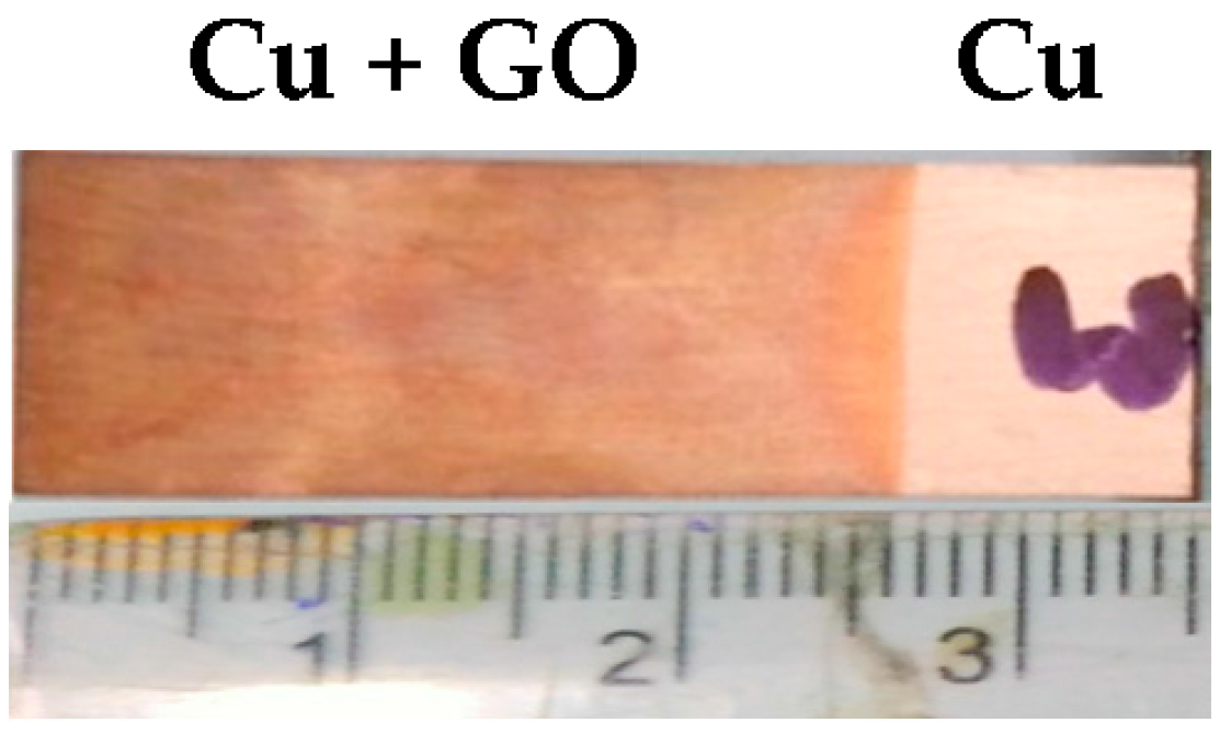
A transparent and very thin and uniform coating of GO (as shown in Figure 2) was obtained upon drying of the film deposited by electrophoretic deposition. The deposited layer (0.3 mg) was smooth and uniform.
3.1. Characterization of Coating
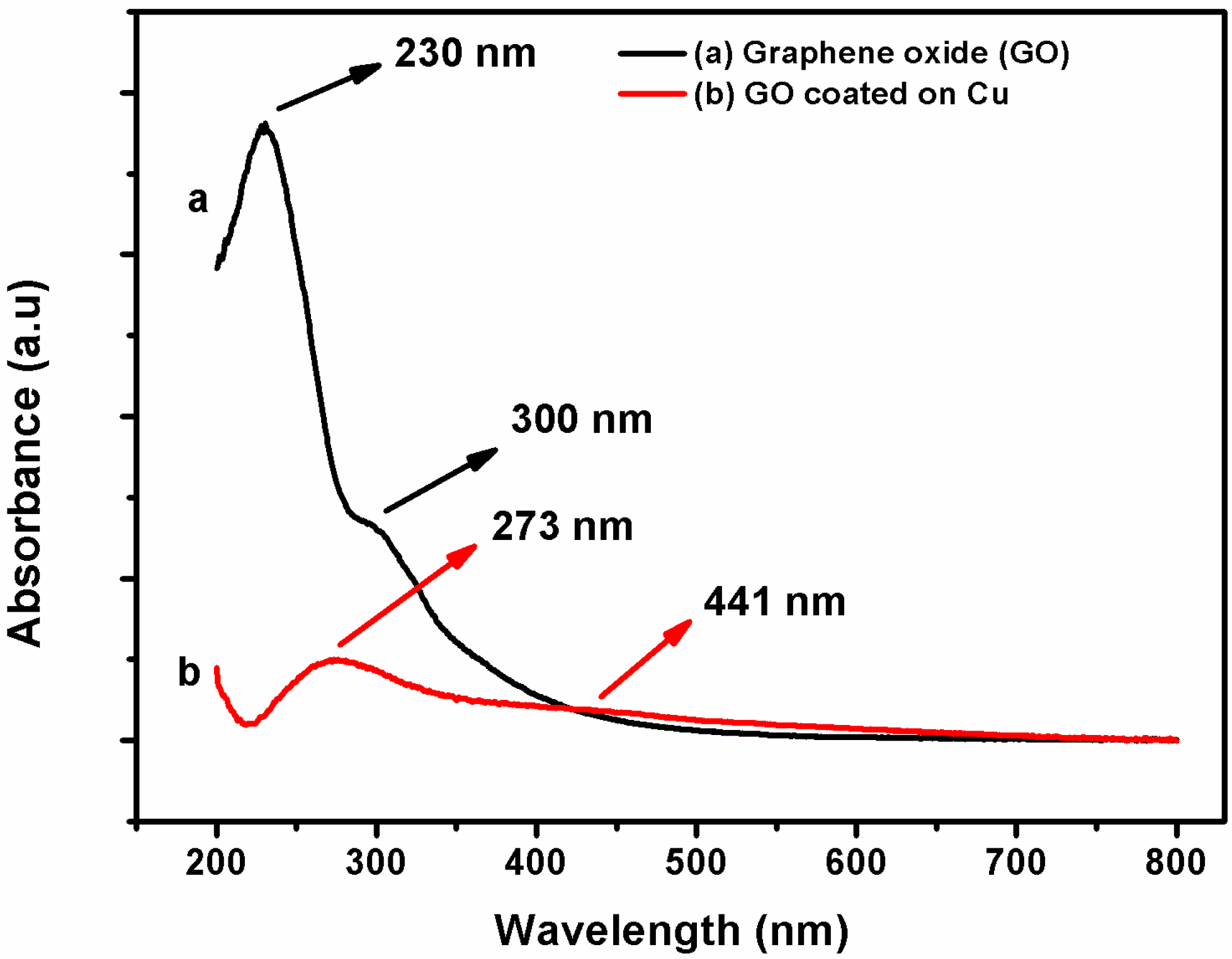
The UV-Visible spectra of GO is shown in Figure 3. In this absorbance spectra, the main spectrum of GO (Figure 3a) has an absorption peak at 230 nm, attributed to π-π* transition of the aromatic C–C ring and weak absorption at 300 nm due to n-π* transition of C–O bond [42]. The GO coated on copper surface was scrapped and was dispersed in de-ionized water for UV analysis. It shows a very low intense absorption peak of π-π* transition of the aromatic C–C ring, which has been red shifted to 273 nm due to the extended conjugation of double bond in the aromatic ring. This red shift indicates the reduction of some functional groups like epoxy, –OH group, etc. Generally, oxidation occurs at anode and reduction at cathode. However, UV analysis of coated GO (Figure 3b), scrapped from copper anode in the electrophoretic deposition, suggests that a partial reduction of GO has taken place at the anode during EPD. The suggested mechanism of reduction is as follows [43]:
RCOO− → RCOO + e− (oxidation of carboxylate)
RCOO → R + CO2 (oxidation decarboxylation)
2R → R–R (dimerization of radicals)
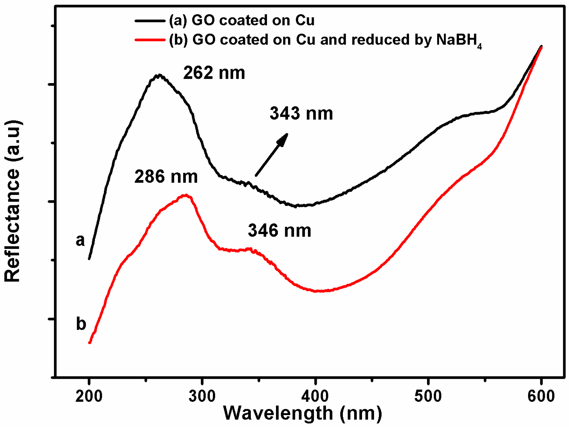
For the characterization of GO coated electrophoretically on copper, UV analysis was done in reflectance mode using the thin film attachment. The results are presented in Figure 4. The spectrum of GO on copper (Figure 4a) shows a reflectance peak at 262 nm due to π-π* transition of the aromatic C–C ring and a reflectance peak at 343 nm due to n-π* transition of C–O bond. The spectrum of GO coated on Cu and completely reduced by NaBH4 has been red shifted and shows a strong reflectance peak at 286 nm for π-π* transition and a shoulder at 346 nm for n-π* transition (Figure 4b). This is partially due to the extended conjugation of double bond in the aromatic ring because of the electrochemical reduction of GO during EPD.
Raman spectroscopy is widely used to characterize crystal structure, disorder, and defects in graphene-based materials. Figure 5 shows the Raman spectra of graphene oxide (GO), GO coated on Cu, and GO coated on Cu and chemically reduced by NaBH4. The D-peak of GO, GO coated Cu, and chemically reduced GO coated Cu located at 1352 cm−1, 1349 cm−1, and 1345 cm−1, respectively, are attributed to defects induced in graphene nano-sheets or their agglomeration. The G-peak for GO, GO coated Cu at 1603 cm−1, and for chemically reduced GO coated Cu at 1589 cm−1 is due to the first order scattering of the E2g phonon of sp2 C-atoms [44]. The absence of two-dimensional (2D)-band in graphene oxide indicates that all graphite layers have been oxidized after oxidation, while the presence of this band in reduced GO coated Cu confirms that the product is composed of a few layered graphene. The increase of the D-peak intensity of reduced GO coated Cu indicates the forming of new graphitic domains, which are smaller in size but more in numbers in comparison to GO coated Cu before reduction. The subsequent increase in D/G intensity ratio from GO to GO coated on Cu and GO coated on Cu after chemical reduction, as shown in figure indicates the presence of localized sp3 defects within the sp2 carbon network due to reduction of exfoliated GO [2].
Attenuated total reflectance Fourier-transform infrared spectroscopy (ATR-FTIR) measurement was employed to characterize the structure and functional groups of the materials. It is used here to investigate the bonding interactions in graphene before and after oxidation, and it is assumed that the intensities of the peaks are directly related to the amount of sample present. Figure 6 shows the stretching of hydroxyl and carboxyl groups in a broad range of 3000–3600 cm−1 for GO, whereas for GO coated Cu and chemically reduced GO coated Cu, there is no stretching of these groups. The C–H stretching for GO shows two sharp peaks at 2918 cm−1 and 2847 cm−1, whereas chemically reduced GO coated Cu show a broad peak in a range of 2987–2847 cm−1. The C=O carbonyl stretching at 1712 cm−1 shows the peak for GO only. This confirms the reduction of GO to rGO. The epoxy C–O–C and alkoxy C–O group stretching frequency show peaks at 1261 cm−1 and 1050 cm−1, respectively. The peak at 2169 cm−1 shows the peak for the presence of CO2 in GO flake. The high intensity of the main peaks in GO confirms the presence of a large amount of oxygen functional groups after the oxidation process. The peak at 1618 cm−1 is related to the bending vibrations of –OH group in adsorbed water molecules. After the reduction of GO, hydroxyl, and carbonyl groups were significantly decreased and the sp2 hybridized in-plane C=C ring stretching at 1538 cm−1 was present. However, in order to effectively eliminate oxygen functional groups on carbon planes, strongly acidic environment might be required [45].
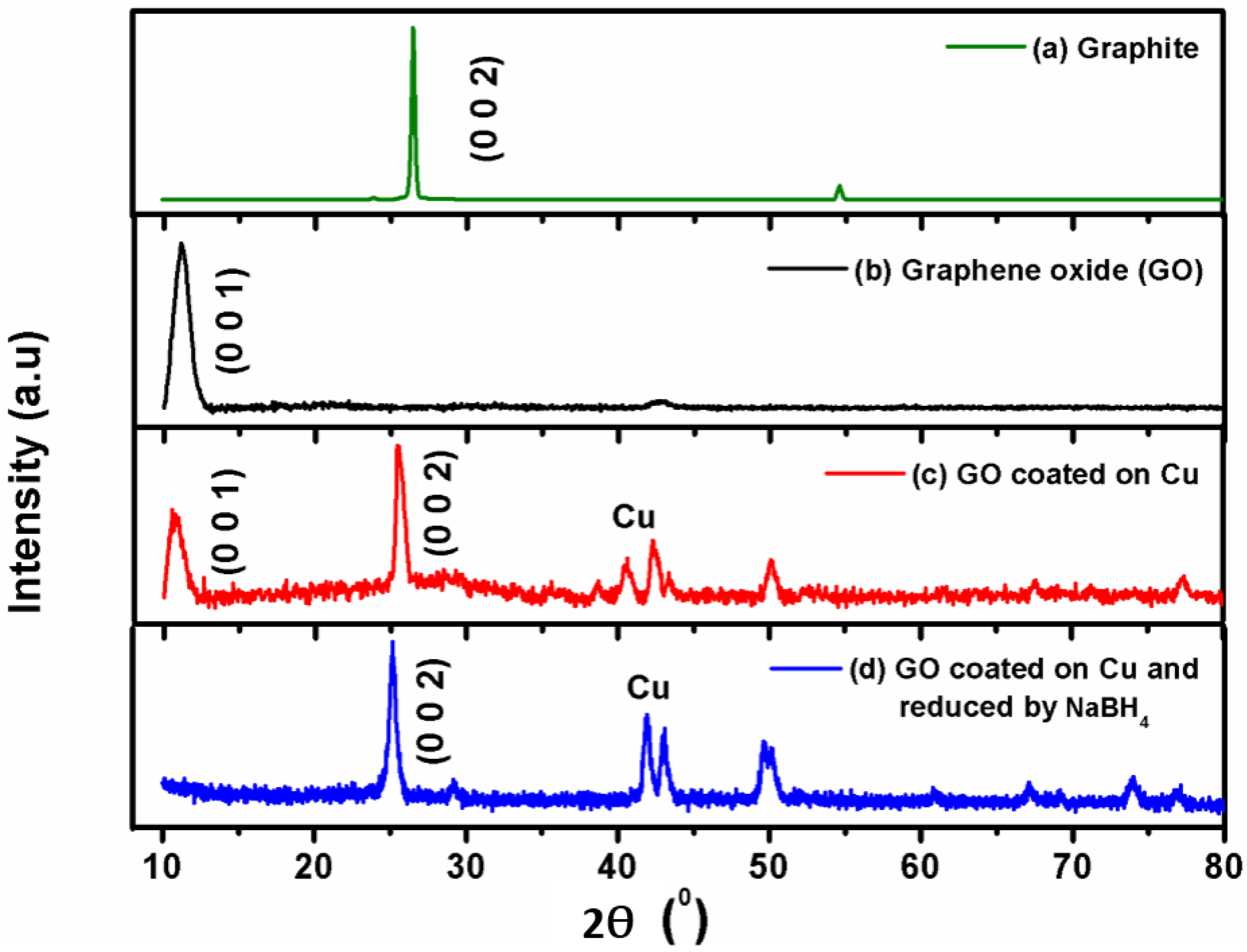
The XRD patterns of graphite, GO, GO on Cu, and GO coated on Cu and reduced by NaBH4 are shown in Figure 7. Pristine graphite shows a strong and sharp diffraction peak at 2θ = 26.5°, corresponding to the highly organized layer structure with an interlayer distance of 0.34 nm along the (002) orientation. After the chemical oxidation and exfoliation, the (002) diffraction peak of graphite is disappeared with the introduction of (001) diffraction peak at 2θ = 11°, which corresponds to GO. An increased interlayer distance between consecutive carbon basal planes is attributed to the intercalation of oxygen containing functional groups, such as hydroxyl, epoxy, carboxyl, and water molecules into carbon layer structure. Thus, the XRD pattern of GO confirms that the original graphite powders had almost been completely oxidized. The GO coated copper on the other hand, exhibits a new diffraction peak at 2θ = 25.5°, which can be explained by the removal of oxygen functional groups, causing a decrease in d-spacing. However, the GO coated on Cu could not be completely reduced through electro-chemical reduction for which a small characteristic diffraction peak of graphene oxide (001) at approximately 2θ = 11° still remained in the XRD spectra [46]. The GO coated on Cu, and reduced by NaBH4 shows a sharp diffraction peak (002) at 2θ = 26.15°, which indicates the removal of oxygen atoms that got into the inter-layer spacing of graphite during the intercalation process. This confirms the reduction of GO to rGO [46]. The short & sharp peak at 2θ = 43° corresponds to the peak of copper.
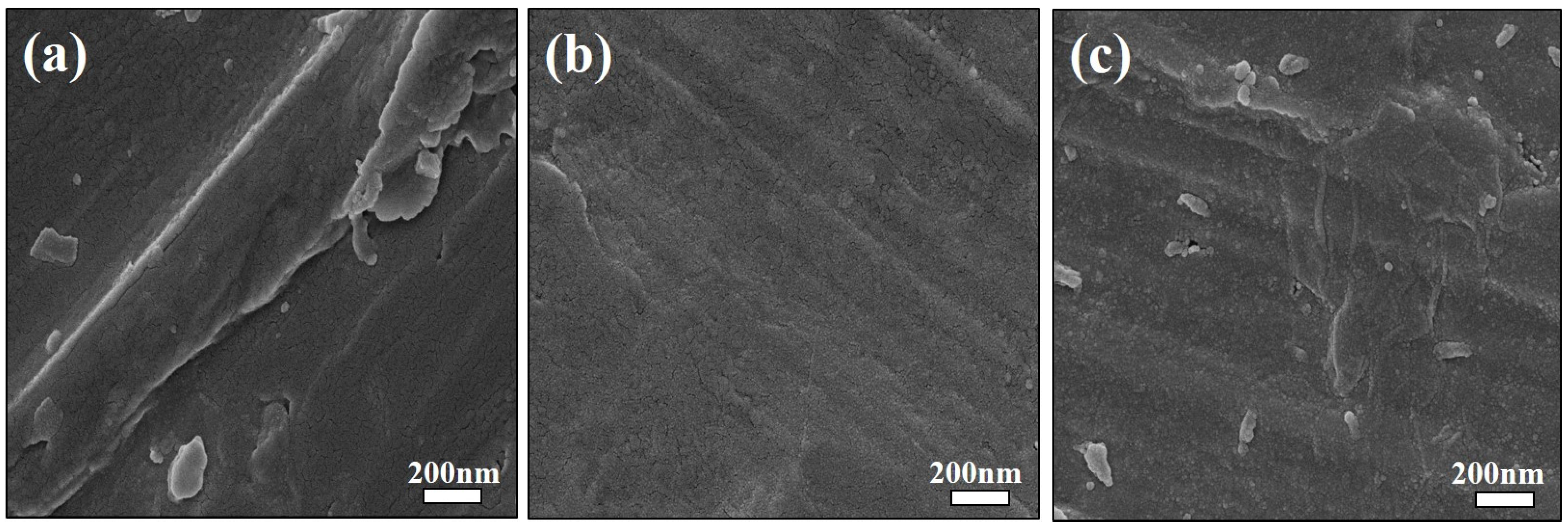
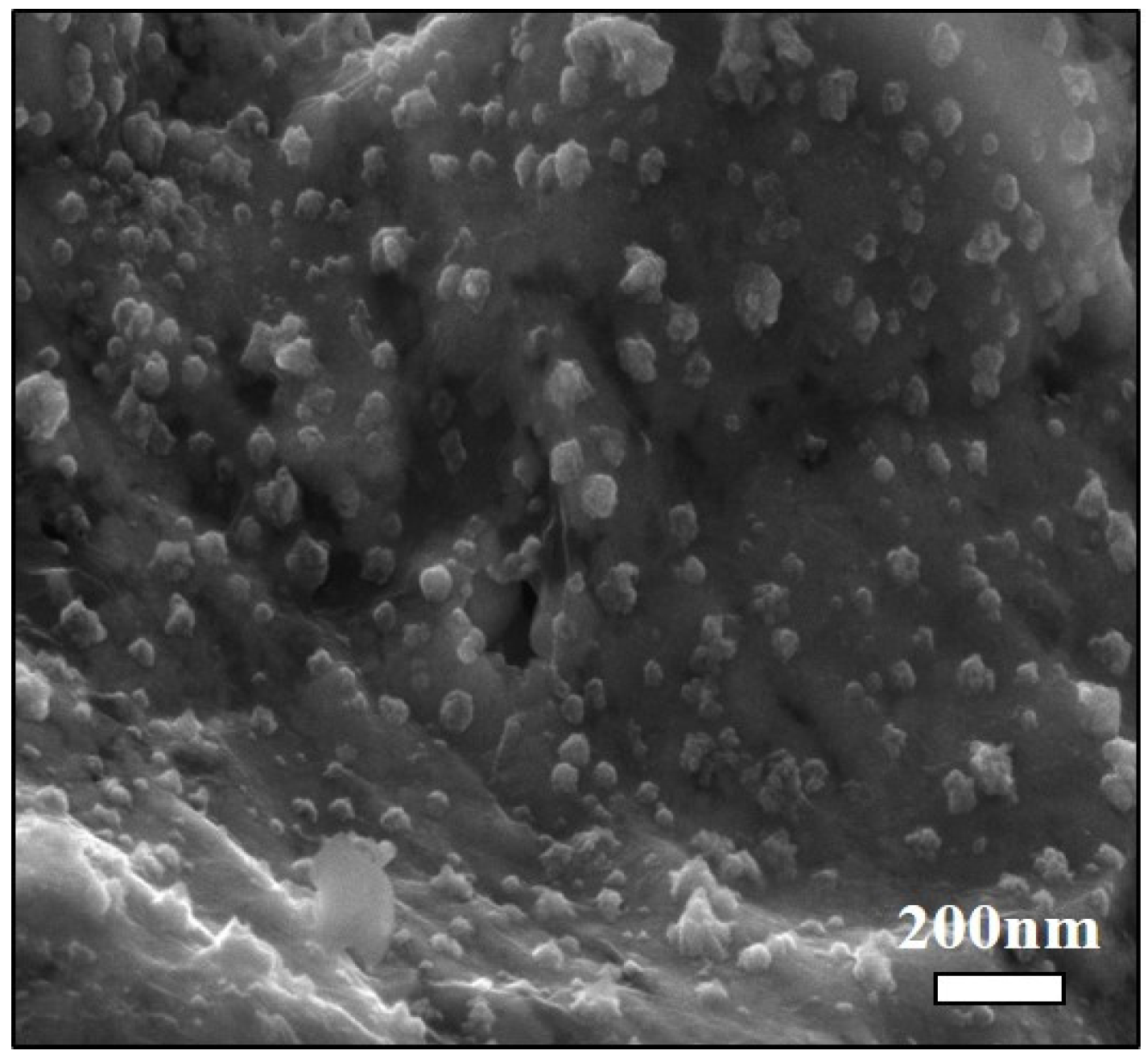
The morphology and structure of GO coated on copper and GO coated on copper and reduced by NaBH4 was investigated through field emission scanning electron microscope (FESEM). Figure 8a presents the representative FESEM image of bare copper. Figure 8b represents a uniform, very thin, and transparent coating of GO sheets on copper substrate. The sheet is so thin that an electron beam can be passed through the sample. It implies that graphene oxide (GO) have well defined and interlinked three-dimensional graphene sheets, forming a porous network that resembles a loose sponge like structure. The nano-particles on the surface of GO sheets are attributed to gold nanoparticles that are deposited during gold sputter coating for FESEM sample preparation. Figure 8c represents FESEM image of chemically reduced GO nano-sheets, revealing a crumpled, rippled, and randomly aggregated structure that is associated with each other, which was the result of reduction in presence of sodium borohydride (NaBH4) [47]. Agglomeration of reduced GO sheets is because of removal of oxygenated species upon reduction of GO. The corrugated morphology suggests the intrinsic nature of graphene, because the 2D membrane structure would be thermodynamically stable via blending [48].
3.2. Corrosion Resistance
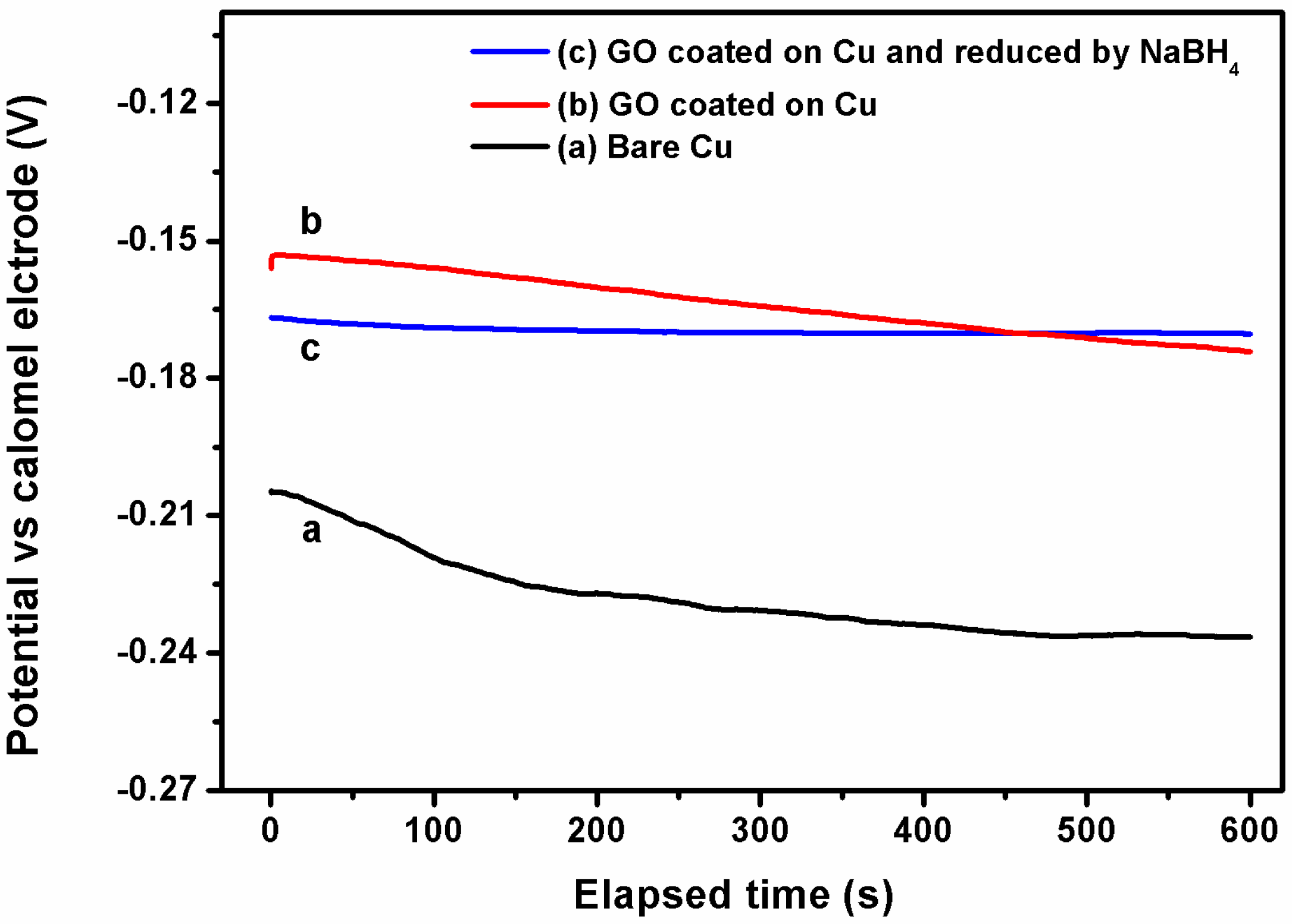
Open circuit potential (OCP) was recorded for bare Cu, GO coated on Cu, and GO coated on Cu and reduced by NaBH4 as a function of time in 3.5 wt % NaCl solution at room temperature. The measurements showed that the potential of bare Cu initially decreases to 30 mV within 5 min, and then remained stable at values close to −236 mV (Figure 9).
The Eocp values for GO coated on Cu and GO coated on Cu and reduced by NaBH4 remained almost stable, at values close to −174 mV and −170 mV by 10 min. Since all of the samples attained a stable OCP in about 10 min, therefore, all subsequent corrosion evaluation tests were conducted after stabilizing the samples in 3.5% NaCl for 10 min. Since Eocp is the measure of corrosion susceptibility, the shift in Eocp values observed on both GO coated on Cu and GO coated on Cu and reduced by NaBH4 towards more positive side when compared to bare copper indicates that GO coated on Cu and chemically reduced GO on Cu increases the corrosion resistance of the Cu substrate compared to bare copper [49].
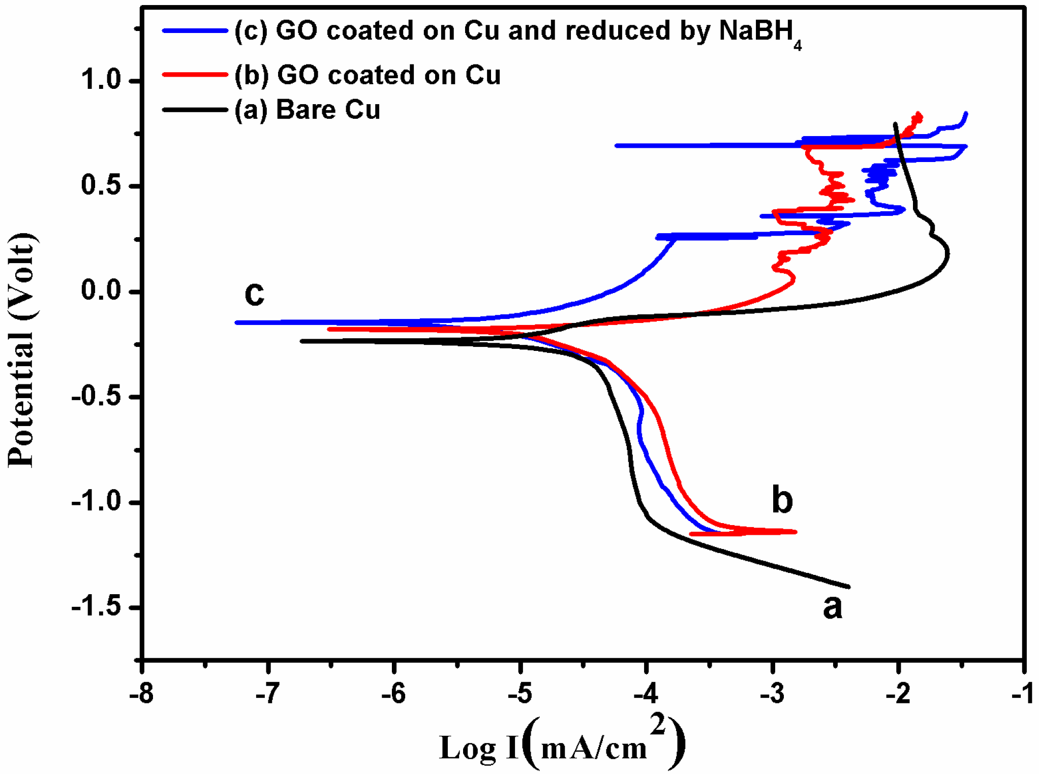
Figure 10 shows the potentiodynamic polarization curves of bare Cu, GO coated on Cu and GO coated on Cu after reduction. During this test, the anodic dissolution rate of Cu at a given potential is estimated by the anodic current densities, while the rate of oxygen reduction reaction determines the cathodic current densities. The polarization curve of GO coated on Cu and GO coated on Cu after reduction exhibits more positive magnitude in comparison to bare Cu, suggesting that GO coated on Cu remarkably decreases the dissolution of copper [20]. The corrosion potential, Ecorr, (i.e., the intercept of the anodic and cathodic regions of the plot) of GO coated on Cu after reduction has more positive value (−145.4 mV) in comparison to GO coated on Cu (−182.2 mV) and bare Cu (−235.3 mV) in saline environment containing 3.5 wt % NaCl solution. This signifies that GO coated on Cu after reduction acts as a very strong passivation layer against ion diffusion and corrosion. On the other hand, the decrease in current density (Icorr) from 15.375 µA/cm2 for bare Cu to 7.01 µA/cm2 for reduced GO coated on Cu proved that GO coating acts as a barrier to the underlying Cu surface and therefore inhibits the Cu attrition.
The ECorr and ICorr values obtained from tafel plot are summarized in Table 1. The corrosion inhibition efficiency (ɳ) and corrosion rate (CR) of GO coated on Cu and chemically reduced GO coated on Cu were estimated by using the following equation [2]:
where, “I” is the polarized current density. The inhibition efficiency of GO coated on Cu was calculated to be 54.40%. The corrosion rate (CR) can be calculated by employing the following equation according to the American Society for Testing and Materials (ASTM) standard G102 [50]:
where, the corrosion rate constant (K) = 3272 mm/year, equivalent weight (EW) = 31.7 gm of Cu, the density (ρ) of Cu = 8.97 gm/cm3 and surface area of the sample (A) = 0.8 cm2.
ɳ = {[Icorr (Cu) – Icorr (GO/Cu)]/Icorr} × 100
CR = K [Icorr/ρA] × EW
The calculated value of corrosion rate (CR) for bare Cu and chemically reduced GO coated on Cu was found to be 0.18 mm/year and 0.08 mm/year, respectively. This observation evidently reveals that GO coating increases the corrosion resistance twice to that of bare Cu, implying much enhanced protection from corrosion.
FESEM micrographs of GO coated on copper and chemically reduced by NaBH4 after 10 min of exposure to 3.5 wt % NaCl solution at room temperature is depicted in Figure 11. The surface of the coated sample seems to degrade at some isolated areas, but is almost undamaged. This reveals the fact that graphene oxide is strongly adhered to the surface of the copper, protecting it from corrosion by the strong salt solution. The spherical dot like morphology on the surface is possibly a result of local aggregation of the reduced graphene oxide (rGO) due to its interaction with NaCl. The stability of reduced graphene oxide (rGO) materials is not well understood till date. Qi et al. [51] examined the electrokinetic properties and aggregation kinetics of three rGOs that were synthesized by reducing graphene oxide (GO) with N2H4, NaBH4, and l-ascorbic acid. In NaCl solution, the critical coagulation concentrations of the materials correlated reasonably with their C/O ratios. The increased aggregation tendency of rGOs was caused mainly by their increased hydrophobicity rather than decreased surface charge negativity. For both monovalent and divalent cations, less densely hydrated cations were more effective in causing aggregation than more densely hydrated cations.
Our results of improvement in corrosion resistance of GO coated on Cu by EPD were comparable to those coated by other methods, such as drop casting reported by Krishnamoorthy et al. [52]. Corrosion potential (Ecorr) of bare Cu measured in 3.5% NaCl reported by them was about −269.89 mV. The Ecorr of GO coated copper substrates exhibited a shift towards the positive side (Ecorr = −131.73 mV). Thus, GO coating significantly improved the corrosion resistance of the copper substrates by decreasing the Icorr. The corrosion inhibition efficiency of Krishnamoorthy et al. [52] was 70% compared to bare copper. In our earlier study [2], the graphene nanosheets coated copper exhibited a very less negative Ecorr value (−211.0 mV) in comparison to bare copper (−691.4 mV), and Icorr value of 4.0 µA/cm2 in comparison to bare copper (38.25 µA/cm2) in 3.5% NaCl. In another study, Sai et al. [53] reported 91% corrosion inhibition efficiency by dip-coated rGO on mild steel when tested in 3.5% NaCl. However, such improvement in corrosion inhibition efficiency was achieved on samples coated for three times by dip coating, because a single dip-coating produced incomplete coverage of the surface. In our study, we have achieved corrosion inhibition efficiency of 54.40% after a single coat by EPD at 10 V for 1 s. Our results adds further evidence to the scientific literature to suggest that GO coating holds a great potential in the fabrication of corrosion-resistant coatings.
4. Conclusions
A thin and uniform coating of graphene oxide (GO) on copper was obtained by electrophoretic deposition from 0.03 wt % aqueous suspension at pH 3.4 on application of 10 V for 1 s. The GO coated on copper was partially reduced during electrophoretic deposition. The GO coated on Cu was completely reduced chemically using aqueous solution of NaBH4 as the reducing agent. Chemical reduction of GO coated on Cu resulted in crumpled, rippled, and randomly aggregated surface structure. UV visible spectra of GO, GO coated on Cu, and GO coated on Cu and reduced by NaBH4 revealed that the peak at 230 nm due to π-π* transition of C–C ring obtained on GO red shifted to 262 nm after electrophoretic deposition. Similarly, the peak at 300 nm (n-π* transition of C–O bond) obtained for GO, red shifted to 343 nm for GO coated Cu. These results confirmed the partial reduction of GO during EPD. After reduction with NaBH4 a strong reflectance peak at 286 nm for π-π* transition and a shoulder at 346 nm for n-π* transition confirmed the complete reduction of GO film. The absence of 2D-band in Raman spectra of GO indicates that all of the graphite layers have been oxidized. Appearance of the 2D band on reduced GO coated on Cu confirmed that the product is composed of layered graphene. A strong peak at 1538 cm−1 in the FTIR spectra of GO coated Cu and reduced by NaBH4 was due to sp2 hybridized in-plane C=C ring stretching. This peak was absent on GO and GO coated on Cu.
The GO coating, as well as reduced GO coating, exhibited an enhanced corrosion resistance when compared to bare copper. The corrosion potential, Ecorr, of GO coated on Cu and reduced by NaBH4 was more positive (−145.4 mV) as compared to GO coated Cu (−182.2 mV) and bare Cu (−235.3 mV). This indicates that reduced GO film on copper acts as very strong passivation layer against ion diffusion and corrosion. The corresponding corrosion current density (Icorr) was much lower (7.01 µA/cm2) for chemically reduced GO coated Cu when compared to 15.375 µA/cm2 for bare Cu, indicating that GO coating acts as a barrier to the underlying Cu surface, and therefore inhibits Cu attrition. The corrosion inhibition efficiency of reduced GO coated Cu was found to be 54.40%. The corrosion rate for bare Cu and reduced GO coated Cu was found to be 0.18 mm/year and 0.08 mm/year, respectively, suggesting that reduced GO coating shows two-fold increase in corrosion resistance when compared to bare Cu.
Acknowledgments
This work was supported with funding from Board of Research for Nuclear Science (BRNS), Mumbai. The authors thank the Director, Institute of Minerals and Materials Technology, Bhubaneswar for permission to publish this paper.
Author Contributions
N. Usha Kiran performed the experiments and wrote the manuscript; Sanjukta Dey performed the corrosion resistance evaluation of the coatings by electrochemical polarization measurements and interpretation of the data; Bimal P. Singh conceived and designed the experiments, contributed in procuring reagents/materials/analysis tools and reviewed the manuscript; Laxmidhar Besra performed the experiments, analyzed the data and reviewed the manuscript.
Conflicts of Interest
The authors declare no conflict of interest.
References
- Rahmanto, W.H.; Gunawan, R.N. Corrosion rate of copper and iron in seawater based on resistance measurement. J. Coast. Dev. 2002, 5, 67–74. [Google Scholar]
- Singh, B.P.; Nayak, S.; Nanda, K.K.; Jena, B.K.; Bhattacharjee, S.; Besra, L. The production of a corrosion resistant graphene reinforced composite coating on copper by electrophoretic deposition. Carbon 2013, 61, 47–56. [Google Scholar] [CrossRef]
- Basu, S.; Singh, P.K.; Huang, J.-J.; Wang, Y.-H. Liquid-Phase Deposition of Al2O3 Thin Films on GaN. J. Electrochem. Soc. 2007, 154, H1041–H1046. [Google Scholar] [CrossRef]
- Silickas, P.; Valiulis, A.V. Liquid-phase deposition and the properties of thin zirconium dioxide films on different substrates. Mater. Sci. 2008, 44, 211–215. [Google Scholar] [CrossRef]
- Talo, A.; Passiniemi, P.; Forsén, O.; Yläsaari, S. Polyaniline/epoxy coatings with good anti-corrosion properties. Synth. Met. 1997, 85, 1333–1334. [Google Scholar] [CrossRef]
- Li, X.; Yu, X.; Han, Y. Polymer thin films for antireflection coatings. J. Mater. Chem. C 2013, 1, 2266–2285. [Google Scholar] [CrossRef]
- Geim, A.K.; Novoselov, K.S. The rise of graphene. Nat. Mater. 2007, 6, 183–191. [Google Scholar] [CrossRef] [PubMed]
- Singh, V.; Joung, D.; Zhai, L.; Das, S.; Khondaker, S.I.; Seal, S. Graphene based materials: Past, present and future. Prog. Mater. Sci. 2011, 56, 1178–1271. [Google Scholar] [CrossRef]
- Sanjinés, R.; Vâju, C.; Smajda, R.; Mionić, M.; Magrez, A. Electrical properties and applications of carbon based nanocomposite materials: An overview. Surf. Coat. Technol. 2011, 206, 727–733. [Google Scholar] [CrossRef]
- Jeon, I.-Y.; Choi, H.-J.; Bae, S.-Y.; Change, D.W.; Baek, J.-B. Wedging graphite into graphene and graphene-like platelets by dendritic. J. Mater. Chem. 2011, 21, 7820–7826. [Google Scholar] [CrossRef] [Green Version]
- Singh, B.P.; Jena, B.K.; Bhattacharjee, S.; Besra, L. Development of oxidation and corrosion resistance hydrophobic graphene oxide-polymer composite coating on copper. Surf. Coat. Technol. 2013, 232, 475–481. [Google Scholar] [CrossRef]
- Tong, Y.; Bohmb, S.; Song, M. Graphene Based Materials and Their Composites as Coatings. Aust. J. Nanomed. Nanotechnol. 2013, 1, 1003. [Google Scholar]
- Yivlialin, R.; Bussetti, G.; Brambilla, L.; Castiglioni, C.; Tommasini, M.; Duò, L.; Passoni, M.; Ghidelli, M.; Casari, C.S.; Li Bassi, A. Microscopic Analysis of the Different Perchlorate Anions Intercalation Stages of Graphite. J. Phys. Chem. C 2017, 121, 14246–14253. [Google Scholar] [CrossRef]
- Dikin, D.A.; Stankovich, S.; Zimney, E.J.; Piner, R.D.; Dommett, G.H.B.; Evmenenko, G.; Nguyen, S.T.; Ruoff, R.S. Preparation and characterization of graphene oxide paper. Nature 2007, 448, 457–460. [Google Scholar] [CrossRef] [PubMed]
- Wang, X.; Zhi, L.; Müllen, K. Transparent, conductive graphene electrodes for dye-sensitized solar cells. Nano Lett. 2008, 8, 323–327. [Google Scholar] [CrossRef] [PubMed]
- Li, X.; Zhang, G.; Bai, X.; Sun, X.; Wang, X.; Wang, E.; Dai, H. Highly conducting graphene sheets and Langmuir–Blodgett films. Nat. Nanotechnol. 2008, 3, 538–542. [Google Scholar] [CrossRef] [PubMed]
- Gilje, S.; Han, S.; Wang, M.; Wang, K.L.; Kaner, R.B. A chemical route to graphene for device applications. Nano Lett. 2007, 7, 3394–3398. [Google Scholar] [CrossRef] [PubMed]
- Tung, V.C.; Allen, M.J.; Yang, Y.; Kaner, R.B. High-throughput solution processing of large-scale graphene. Nat. Nanotechnol. 2009, 4, 25–29. [Google Scholar] [CrossRef] [PubMed]
- Prasai, D.; Tuberquia, J.C.; Harl, R.R.; Jennings, G.K.; Rogers, B.R.; Bolotin, K.I. Graphene: Corrosion-inhibiting coating. ACS Nano 2012, 6, 1102–1108. [Google Scholar] [CrossRef] [PubMed]
- Narula, U.; Tan, C. Determining the Parameters of Importance of a Graphene Synthesis Process Using Design-of-Experiments Method. Appl. Sci. 2016, 6, 204. [Google Scholar] [CrossRef]
- Singh Raman, R.K.; Chakraborty Banerjee, P.; Lobo, D.E.; Gullapalli, H.; Sumandasa, M.; Kumar, A.; Choudhary, L.; Tkacz, R.; Ajayan, P.M.; Majumder, M. Protecting copper from electrochemical degradation by graphene coating. Carbon 2012, 50, 4040–4045. [Google Scholar] [CrossRef]
- Kirkland, N.T.; Schiller, T.; Medhekar, N.; Birbilis, N. Exploring graphene as a corrosion protection barrier. Corros. Sci. 2012, 56, 1–4. [Google Scholar] [CrossRef]
- Wang, G.; Zhang, M.; Zhu, Y.; Ding, G.; Jiang, D.; Guo, Q.; Liu, S.; Xie, X.; Chu, P.K.; Di, Z.; et al. Direct growth of graphene film on germanium substrate. Sci. Rep. 2013, 3, 2465. [Google Scholar] [CrossRef] [PubMed]
- Geckle, R.J.; Mroczkowski, R.S. Corrosion of Precious Metal Plated Copper Alloys Due to Mixed Flowing Gas Exposure. IEEE Trans. Compon. Hybrids Manuf. Technol. 1991, 14, 162–169. [Google Scholar] [CrossRef]
- Chen, S.; Brown, L.; Levendorf, M.; Cai, W.; Ju, S.-Y.; Edgeworth, J.; Li, X.; Magnuson, C.W.; Velamakanni, A.; Piner, R.D.; et al. Oxidation resistance of graphene-coated Cu and Cu Ni alloy. ACS Nano 2011, 5, 1321–1327. [Google Scholar] [CrossRef] [PubMed]
- Yang, L. Coatings for Corrosion Protection of Metals and Alloys. Master’s Thesis, McMaster University, Hamilton, ON, Canada, 2012. [Google Scholar]
- Zhou, X. Graphene Oxidation Barrier Coating. Bachelor’s Thesis, University of Colorado, Boulder, CO, USA, 2011. [Google Scholar]
- Besra, L.; Liu, M. A review on fundamentals and applications of electrophoretic deposition (EPD). Prog. Mater. Sci. 2007, 52, 1–61. [Google Scholar] [CrossRef]
- Besra, L.; Uchikoshi, T.; Suzuki, T.S.; Sakka, Y. Bubble-free aqueous electrophoretic deposition (EPD) by pulse-potential application. J. Am. Ceram. Soc. 2008, 91, 3154–3159. [Google Scholar] [CrossRef]
- Ferrari, B.; Moreno, R. Electrophoretic deposition of aqueous alumina slips. J. Eur. Ceram. Soc. 1997, 17, 549–556. [Google Scholar] [CrossRef]
- An, S.J.; Zhu, Y.; Lee, S.H.; Stoller, M.D.; Emilsson, T.; Park, S.; Velamakanni, A.; An, J.; Ruoff, R.S. Thin film fabrication and simultaneous anodic reduction of deposited graphene oxide platelets by electrophoretic deposition. J. Phys. Chem. Lett. 2010, 1, 1259–1263. [Google Scholar] [CrossRef]
- Park, J.H.; Park, J.M. Electrophoretic deposition of graphene oxide on mild carbon steel for anti-corrosion application. Surface Coat. Technol. 2014, 254, 167–174. [Google Scholar] [CrossRef]
- He, W.; Zhu, L.; Chen, H.; Wang, Y.; Li, W.; Liu, H.; Wang, Y. Electrophoretic deposition of graphene oxide as a corrosion inhibitor for sintered NdFeB. Appl. Surface Sci. 2013, 279, 416–423. [Google Scholar] [CrossRef]
- Singh, D. Electrophoretic Deposition of Graphene on Copper and its Corrosion Behaviour. Master’s Thesis, NIT Rourkela, Odisha, India, 2017. [Google Scholar]
- Raza, M.A.; Rehman, Z.U.; Ghauri, F.A.; Ahmad, A.; Ahmad, R.; Raffi, M. Corrosion study of electrophoretically deposited graphene oxide coatings on copper metal. Thin Solid Films 2016, 620, 150–159. [Google Scholar] [CrossRef]
- Raza, M.A.; Ali, A.; Ghauri, F.A.; Aslam, A.; Yaqoob, K.; Wasay, W.; Raffi, M. Electrochemical behavior of graphene coatings deposited on copper metal by electrophoretic deposition and chemical vapor deposition. Surface Coat. Technol. 2017. In press. [Google Scholar] [CrossRef]
- Al-Sammarraie, A.M.A.; Raheema, M.H. Electrodeposited Reduced Graphene Oxide Films on Stainless Steel, Copper, and Aluminum for Corrosion Protection Enhancement. Int. J. Corros. 2017, 2017, 6939354. [Google Scholar] [CrossRef]
- Diba, M.; Fam, D.W.H.; Boccaccini, A.; Shaffer, M.S.P. Electrophoretic deposition of graphene-related materials: A review of the fundamentals. Prog. Mater. Sci. 2016, 82, 83–117. [Google Scholar] [CrossRef]
- Shahriary, L.; Athawale, A. Graphene Oxide Synthesized by using Modified Hummers Approach. Int. J. Renew. Energy Environ. Eng. 2014, 2, 58–63. [Google Scholar]
- Kang, J.H.; Kim, T.; Choi, J.; Park, J.; Kim, Y.S.; Chang, M.S.; Jung, H.; Park, K.T.; Yang, S.J.; Park, C.R. Hidden Second Oxidation Step of Hummers Method. Chem. Mater. 2016, 28, 756–764. [Google Scholar] [CrossRef]
- Yang, Z.; Zheng, Q.; Qiu, H.; LI, J.; Yang, J. A simple method for the reduction of graphene oxide by sodium borohydride with CaCl2 as a catalyst. New Carbon Mater. 2015, 30, 41–47. [Google Scholar] [CrossRef]
- De, D.; Chakraborty, M.; Majumdar, S.; Giri, S. Bandgap engineering through nanocrystalline magnetic alloy grafting on reduced graphene oxide. Phys. Chem. Chem. Phys. 2014, 16, 19661–19667. [Google Scholar] [CrossRef] [PubMed]
- Lih, E.T.Y.; Zaid, R.B.M.; Ling, T.L.; Chong, K.F. Facile Corrosion Protection Coating from Graphene. Int. J. Chem. Eng. Appl. 2012, 3, 453. [Google Scholar] [CrossRef]
- Sobon, G.; Sotor, J.; Jagiello, J.; Kozinski, R.; Zdrojek, M.; Holdynski, M.; Paletko, P.; Boguslawski, J.; Lipinska, L.; Abramski, K.M. Graphene oxide vs. reduced graphene oxide as saturable absorbers for Er-doped passively mode-locked fiber laser. Opt. Express 2012, 20, 19463–19473. [Google Scholar] [CrossRef] [PubMed]
- Loryuenyong, V.; Totepvimarn, K.; Eimburanapravat, P.; Boonchompoo, W.; Buasri, A. Preparation and Characterization of Reduced Graphene Oxide Sheets via Water-Based Exfoliation and Reduction Methods. Adv. Mater. Sci. Eng. 2013, 2013, 923403. [Google Scholar] [CrossRef]
- Fu, C.; Zhao, G.; Zhang, H.; Li, S. Evaluation and Characterization of Reduced Graphene Oxide Nanosheets as Anode Materials for Lithium-Ion Batteries. Int. J. Electrochem. Sci 2013, 8, 6269–6280. [Google Scholar] [CrossRef]
- Thema, F.T.; Moloto, M.J.; Dikio, E.D.; Nyangiwe, N.N.; Kotsedi, L.; Maaza, M.; Khenfouch, M. Synthesis & characterization of graphene thin films by chemical reduction of exfoliated and intercalated graphite oxide. J. Chem. 2013, 2013, 150536. [Google Scholar] [CrossRef]
- Antony, R.P.; Preethi, L.K.; Gupta, B.; Mathews, T.; Dash, S.; Tyagi, A.K. Efficient electrocatalytic performance of thermally exfoliated reduced graphene oxide-Pt hybrid. Mater. Res. Bull. 2015, 70, 60–67. [Google Scholar] [CrossRef]
- Mišković-Stanković, V.; Jevremović, I.; Jung, I.; Rhee, K. Electrochemical study of corrosion behavior of graphene coatings on copper and aluminum in a chloride solution. Carbon 2014, 75, 335–344. [Google Scholar] [CrossRef]
- ASTM G102-89(2015)e1 Standard Practice for Calculation of Corrosion Rates and Related Information from Electrochemical Measurements; ASTM (American Society for Testing and Materials) International: West Conshohocken, PA, USA, 2015.
- Qi, Y.; Xia, T.; Li, Y.; Duan, L.; Chen, W. Colloidal Stability of Reduced Graphene Oxide Materials Prepared Using Different Reducing Agents. Environ. Sci. Nano 2016, 3, 1062–1071. [Google Scholar] [CrossRef]
- Krishnamoorthy, K.; Ramadoss, A.; Kim, S.-J. Graphene Oxide Nanosheets for Corrosion-Inhibiting Coating. Sci. Adv. Mater. 2013, 5, 406–410. [Google Scholar] [CrossRef]
- Sai Pavan, A.S.; Ramanan, S.R. A study on corrosion resistant graphene films on low alloy steel. Appl. Nanosci. 2016, 6, 1175–1181. [Google Scholar] [CrossRef]
Figure 1.
Schematic of Electrophoretic deposition process for coating graphene oxide on copper.
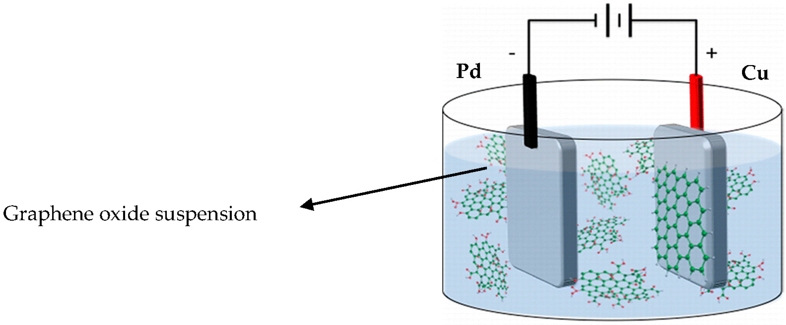
Figure 2.
Photograph of copper substrate coated with graphene oxide (GO).

Figure 3.
UV-Visible spectrum of (a) GO & (b) GO coated on copper (Cu).

Figure 4.
UV-Visible spectrum of (a) GO coated on Cu, and (b) GO coated on Cu and reduced by NaBH4, in reflectance mode.
Figure 4.
UV-Visible spectrum of (a) GO coated on Cu, and (b) GO coated on Cu and reduced by NaBH4, in reflectance mode.

Figure 5.
Raman spectroscopy of (a) graphene oxide (GO), (b) GO coated on Cu, and (c) GO coated on Cu and reduced by NaBH4.
Figure 5.
Raman spectroscopy of (a) graphene oxide (GO), (b) GO coated on Cu, and (c) GO coated on Cu and reduced by NaBH4.

Figure 6.
Attenuated total reflectance Fourier-transform infrared spectroscopy (ATR-FTIR) spectroscopy for (a) graphene oxide, (b) GO coated on Cu, and (c) GO coated on Cu and reduced by NaBH4.
Figure 6.
Attenuated total reflectance Fourier-transform infrared spectroscopy (ATR-FTIR) spectroscopy for (a) graphene oxide, (b) GO coated on Cu, and (c) GO coated on Cu and reduced by NaBH4.
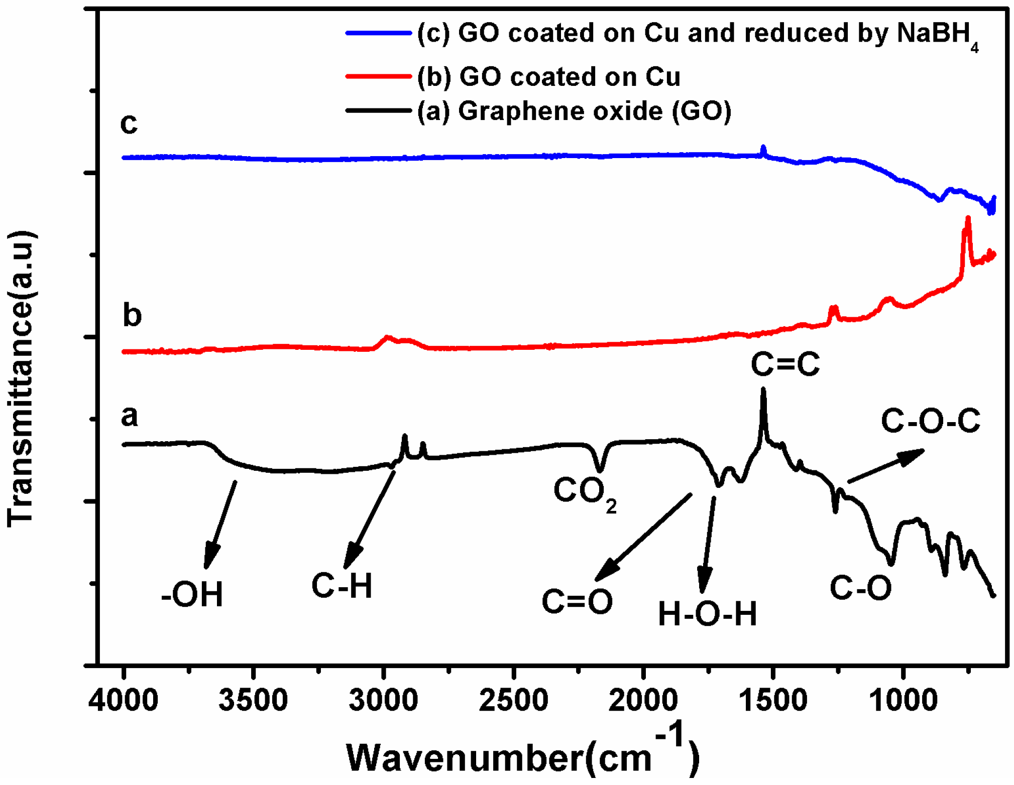
Figure 7.
XRD patterns recorded for (a) pristine graphite, (b) graphene oxide (GO), (c) GO coated on Cu, and (d) GO coated on Cu and reduced by NaBH4.
Figure 7.
XRD patterns recorded for (a) pristine graphite, (b) graphene oxide (GO), (c) GO coated on Cu, and (d) GO coated on Cu and reduced by NaBH4.

Figure 8.
FESEM images of (a) bare copper, (b) GO coated copper, and (c) GO coated on copper and reduced by sodium borohydride (NaBH4).
Figure 8.
FESEM images of (a) bare copper, (b) GO coated copper, and (c) GO coated on copper and reduced by sodium borohydride (NaBH4).

Figure 9.
Open circuit potential (OCP) of (a) bare Cu; (b) GO coated on Cu; and, (c) GO coated on Cu and reduced by NaBH4.
Figure 9.
Open circuit potential (OCP) of (a) bare Cu; (b) GO coated on Cu; and, (c) GO coated on Cu and reduced by NaBH4.

Figure 10.
Tafel polarization curve (TPC) of (a) bare copper, (b) GO coated on Cu, and (c) GO coated on Cu and reduced by NaBH4.
Figure 10.
Tafel polarization curve (TPC) of (a) bare copper, (b) GO coated on Cu, and (c) GO coated on Cu and reduced by NaBH4.

Figure 11.
Field emission scanning electron microscope (FESEM) image of GO coated on Cu and chemically reduced by NaBH4 after corrosion test in 3.5% NaCl solution.
Figure 11.
Field emission scanning electron microscope (FESEM) image of GO coated on Cu and chemically reduced by NaBH4 after corrosion test in 3.5% NaCl solution.


Table 1.
Ecorr, Icorr values obtained from Figure 10 and calculated corrosion rate and inhibition efficiency.
Table 1.
Ecorr, Icorr values obtained from Figure 10 and calculated corrosion rate and inhibition efficiency.
| Sample | Ecorr (mV) | Icorr (µA/cm2) | Corrosion Rate (mm/year) | Inhibition Efficiency (%) |
|---|---|---|---|---|
| Bare copper | −235.3 | 15.375 | 0.18 | – |
| GO Coated copper | −182.2 | 12.44 | 0.15 | 19.08 |
| GO Coated Cu after reduction | −145.4 | 7.01 | 0.08 | 54.40 |
© 2017 by the authors. Licensee MDPI, Basel, Switzerland. This article is an open access article distributed under the terms and conditions of the Creative Commons Attribution (CC BY) license (http://creativecommons.org/licenses/by/4.0/).
Share and Cite
MDPI and ACS Style
Usha Kiran, N.; Dey, S.; Singh, B.P.; Besra, L. Graphene Coating on Copper by Electrophoretic Deposition for Corrosion Prevention. Coatings 2017, 7, 214. https://doi.org/10.3390/coatings7120214
AMA Style
Usha Kiran N, Dey S, Singh BP, Besra L. Graphene Coating on Copper by Electrophoretic Deposition for Corrosion Prevention. Coatings. 2017; 7(12):214. https://doi.org/10.3390/coatings7120214
Chicago/Turabian StyleUsha Kiran, N., Sanjukta Dey, Bimal P. Singh, and Laxmidhar Besra. 2017. "Graphene Coating on Copper by Electrophoretic Deposition for Corrosion Prevention" Coatings 7, no. 12: 214. https://doi.org/10.3390/coatings7120214
Note that from the first issue of 2016, this journal uses article numbers instead of page numbers. See further details here.