1. Introduction
Injection moulding is probably the most widely used plastics manufacturing technology. Nowadays, increasing requirements demanded by designers have driven the use of short glass fibers as reinforcements in many parts, namely for the automotive industry. Abrasion is a typical phenomenon in the plastic injection moulding process and it becomes even more important when plastics are reinforced with glass fibres [
1,
2,
3,
4,
5]. Otherwise, maintenance operations related to moulds represent the costs and inactivity periods of the mould which affect the competitiveness of the process and are strongly connected to the concept of the life cycle cost [
6].
New developments in the polymer industry led to the use of new polymer formulations and blends that are more and more aggressive to steel mould cavities due to gases generated into the mould, causing serious corrosion problems, which bring new challenges to the coatings research and industry [
7]. This problem is magnified by the temperature effect [
8], and it is even more important when we are talking about lighting reflector systems and other automotive parts where transparency and/or surface quality are critical requirements for the customer and no scratches or other scars are allowed [
7]. The Fresnel lens, manufactured by injection moulding, also requires a high quality level, preventing the occurrence of any kind of superficial defects in the mould cavities [
9]. In these cases, usually no reinforcements are applied, and the corrosion and the high pressures exerted into the mould are the main problems to overcome.
However, despite some other important issues related to mould cavity degradation, such as adhesion and fatigue, abrasion plays an important role, severely affecting the surface quality of the mould and, subsequently, the quality and brightness of the injected part’s surface. Indeed, the natural motion of the fibre tips during the injection flow induces small scratches both in the screw and barrels of the injection machine as well as in the mould cavity, leading to bright degradation of the mould cavity surface. Tribological problems associated with the plastics moulding process can often be solved by an appropriate surface modification. Several techniques can be efficient to increase the wear behaviour of the mould cavity surface or other mechanical tools, such as ion implantation, physical vapour deposition (PVD), chemical vapour deposition (CVD), and standard diffusion processes, namely plasma nitriding [
10,
11,
12,
13].
Some authors even developed test models in order to simulate the tribological mechanisms involved inside the injection machine barrel, but without complete success, because only some of the main wear mechanisms were effectively tested [
14]. However, there are other subjects that deserve our attention, namely the heat insulation and/or heat transfer phenomena that cannot be neglected with the coating application, constituting a new concern in the coating selection process [
15]. Effectively, the coating must help to improve the wear resistance but it must also help to maintain or even decrease the injection cycle time, leading to a productivity improvement by keeping or improving the part cooling process after injection.
In order to overcome these problems, some authors have investigated a diversified number of surface treatments and tribological coatings [
1,
2,
3,
5,
15,
16,
17,
18,
19,
20]. In fact, recent developments in coatings technology allow a multifaceted approach to each problem, using mono- or multilayered coatings, single composition or graded layers, conventional or nanostructured films. More recently, some authors have tested selected films by submitting them to real injection conditions [
1,
2,
3,
21], obtaining results that allow us to think that coatings should be applied to moulds in a competitive way. The wear improvement of some steel mould inserts was also tested using a polycrystalline diamond [
22] provided with an interlayer in order to avoid the diffusion of C into the Fe (substrate).
In this work, two dissimilar approaches were conducted using different coating concepts: two monolayer films (TiAlN and TiAlSiN) and two multilayer nanostructured coatings (CrN/TiAlCrSiN and CrN/CrCN/DLC). The main goal of this work was to characterise and compare the wear behaviour of these coatings under real conditions of plastic injection moulding, using glass fibre–reinforced polypropylene. This work also intended to find a competitive way to increase the life cycle of the moulds, minimizing maintenance operations and costs.
2. Materials and Methods
2.1. Substrates Material and Preparation
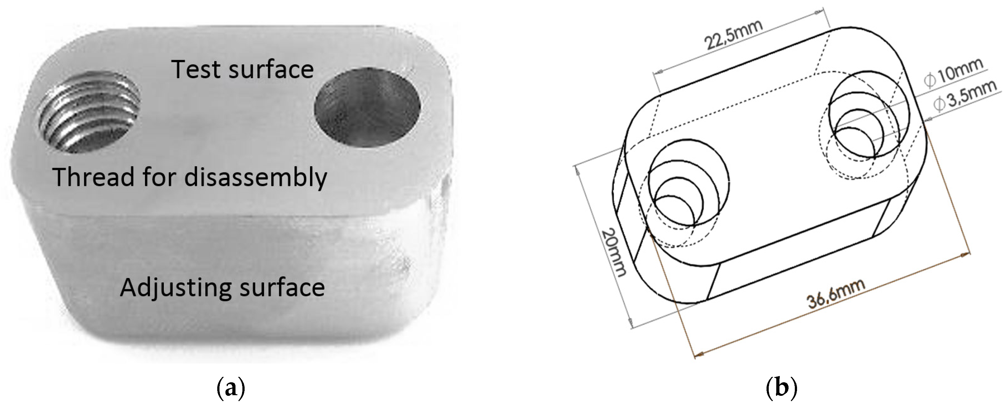
Plastic injection moulds manufacturers typically use AISI P20 tool steel (Bohler Uddeholm, Vienna, Austria) as main material for mould cavities, which is usually supplied in the hardened state. Thus, this material was used as substrate for this work. AISI P20 steel was subject to mass spectroscopy analysis and the chemical composition (wt %) obtained was the following one: 0.35% C, 0.29% Si, 1.95% Cr, 1.39% Mn, 0.19% Mo, 1.00% Ni and 0.01% S. The hardness of the steel was assessed using a universal hardness tester EMCO (model M4U, EMCO-TEST Prüfmaschinen GmbH, Kellau, Kuchl, Austria) carrying out five tests and taking the average value of 380 HBW 2.5/187.5/5. In order to carry out the wear tests, two different kinds of samples were used: laboratorial samples with a quadrangular shape of 25 mm × 25 mm and 2 mm thickness, and industrial samples with a specific shape allowing its insertion on proper cavities machined in the mould, allowing the contact of the samples with the plastic flow during each injection cycle. The cavities dug into the mould have a slight conical shape, allowing a better adjustment of the samples in the cavity. The shape of the industrial samples can be observed in
Figure 1. These samples were placed in the plastic feed channel of the mould, letting its surface coincident with the remaining surface of the feed channel. Surface of both kind of samples was milled in a Computer Numeric Control machining centre and further ground until an average surface roughness of 0.06 μm has been retrieved, which is enough to observe wear phenomena and is similar to surface roughness usually used in this kind of injection tools.
2.2. Coatings Deposition
Coatings were produced using a CemeCon CC800/9 PVD unbalanced magnetron sputtering reactor (CemeCon, A.G., Wurselen, Germany). The following deposition parameters were similar for every coatings here referred: Gas pressure 500 mPa, Temperature 500 °C, Target power density 16 A·cm
−2, Bias in the range of −120 V to −50 V, and deposition time 4 h. However, in order to produce each coating, different targets and gases were used, as pointed in
Table 1, which summarises these conditions.
In order to ensure the correct exposure of the samples to the targets and the best homogeneity of the films, sample’s holder was animated with a circular motion of 1 rotation per minute.
In the particular case of the CrN/CrCN/DLC multi-layered coating, the CrN bottom and intermediate layers were generated from two Cr targets using N and Ar+ feed gas, when for the last one C2H2 was added to N and Ar+. For the top layer, the Cr targets were hidden behind the shutters and two graphite targets were exposed.
2.3. Coatings Characterization
After deposition, both film thickness and morphology were assessed by SEM (scanning electron microscopy, FEI, Hillsboro, OR, USA) using a FEI Quanta 400FEG scanning electron microscope provided with an EDAX Genesis X-ray spectroscope (EDS—energy dispersive spectroscopy, EDAX, Mahwah, NJ, USA). For the thickness measurement, a metallographic preparation was done; samples were partially cut in the reverse side of the coating and then they are submerged in liquid nitrogen during 20 min in order to promote a brittle behavior. At that time, samples were taken and mechanically broken, minimizing by this way plastic deformations close to the cutting edge. Then, they were embedded in resin with cross section turned to the working face. Further, the assembled set was ground with F1200 sandpaper until main grooves disappear and then, it was polished with diamond grit solutions of 3 and 1 μm during 10 min each one. Surface morphology and roughness were also evaluated by Atomic Force Microscopy (AFM) (VEECO Instruments, Ltd., Woodbury, NY, USA) using a VEECO Multimode atomic force microscope system (7 nm tip radius) provided with the NanoScope 6.13 software (version 6.13, Bruker, New York, NY, USA). In these analyses, two different areas were considered: 10 μm × 10 μm and 50 μm × 50 μm, comparing the results. A CAMECA Electron Probe Micro-Analysis (EPMA) system (SX-50 model, CAMECA Instruments, Inc., Madison, WI, USA) was also used equipped with wavelength dispersive spectroscopy (WDS) system (version 2.0, CAMECA Instruments, Inc., Madison, WI, USA), allowing confirm the coatings chemical composition. Micro-hardness was also quantified using Fischerscope® H100 equipment (Fischerscope, Windsor, CT, USA), provided with Vickers indenter. A normal load of 50 mN was selected keeping it constant during 30 s, avoiding by this way creep phenomena. This equipment produces a values chart that allows obtaining “load–depth” curves, which let to compute hardness and Young’s modulus values.
2.4. Adhesion Analysis
The adhesion between each coating and substrate was assessed by scratch test and Rockwell indentation. Scratch tests were carried out using a CSM REVETEST equipment (CSEM, Neuchatel, Switzerland) following the procedures recommended by the BS EN 1071-3 (2005) standard [
23]. The normal load was increasing from 0 to 80 N using a growing up rate of 100 N·min
−1 and the indenter sliding speed used was 10 mm·min
−1. Regarding the surface texture effect due to grinding process, two orthogonal measurements were considered allowing to understand the texture effect on the adhesion failure mechanisms. In each orthogonal direction three tests were made in order to maximise the results accuracy. Then, grooves were carefully observed by optical microscopy, correlating the distance of the groove and film detachment phenomena detected on the scratch with the applied load in each point. The grooves observation lets identifying when cohesive and adhesive failures occur, allowing to determine the corresponding load. Another technique was also used permitting to confirm qualitative results. Following the VDI 3198:1991 standard [
24], Rockwell indentations were done at 294 N (30 kgf) and 980 N (100 kgf) normal loads, using an EMCO M4U 025 Universal Hardness Tester (EMCO-TEST Prüfmaschinen GmbH, Kellau, Kuchl, Austria). Indentation borders were observed in order to identify the presence of cracks and its pattern.
2.5. Micro-Abrasion Tests
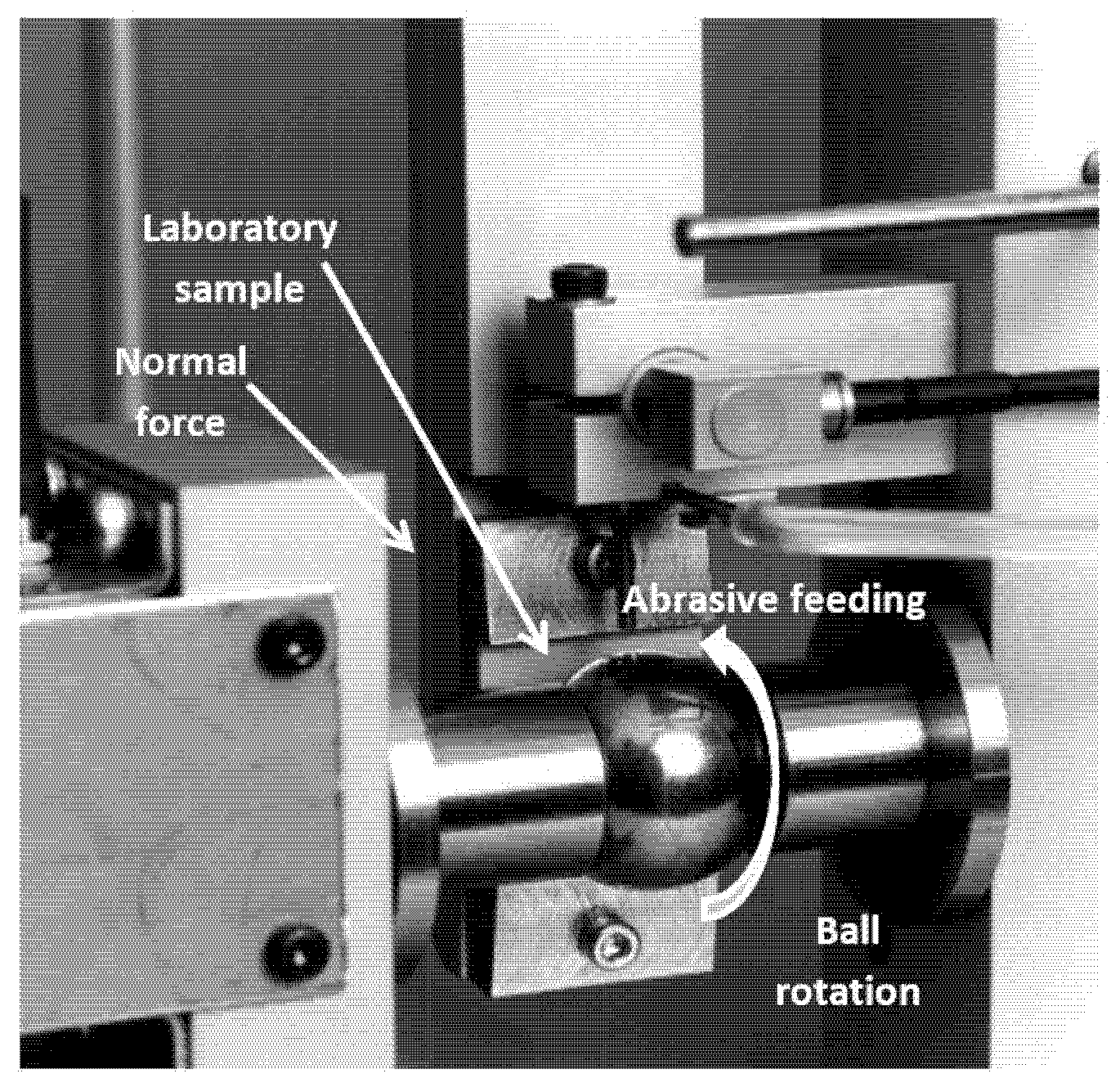
In order to evaluate the wear behaviour of the three coatings and obtain comparable results with other types of coatings, micro-abrasion test configuration is an accurate option, being perfectly suitable for thin films wear characterization. Thus, a PLINT TE 66 tribometer (
Figure 2) using ball-cratering configuration was used. In this test, a ball of AISI 52100 steel with 25 mm diameter was used as counter body. This ball, initially in polished state, was etched using a 10% NITAL solution during 20 s, increasing its surface roughness and allowing better abrasive particles motion. These tests use abrasive slurry composed by 35.4 g of SiC F1200 powder (following FEPA 42-2:2006 standard [
25]), with average particle size of 4.3 μm, standard deviation 1.4 μm, homogeneously distributed in 100 mL distilled water. This slurry is continuously stirred by a magnetic issue into a glass container, during the wear tests. The sample surface in test is pressed against the ball by a vertical bar sustained by a pivot system, rotating on it. The ball rotation speed was 80 rpm, corresponding to 0.105 m·s
−1 and a normal load of 0.25 N was applied in all tests. Three different test lengths were agreed: 200, 500 and 700 cycles, corresponding to sliding distances of 15.71, 39.27 and 54.98 m, respectively. Attending each test conditions set, five different tests were carried out trying to increase the accuracy of the results. After the tests, all wear scars were observed by optical microscopy, using an OLYMPUS BX51M microscope provided with 12.5 megapixel OLYMPUS digital camera and AnalySIS DOCU image software (version 5.0, Olympus, Tokyo, Japan). Some results were later explored by SEM, using the above-mentioned equipment.
2.6. Industrial Wear Tests
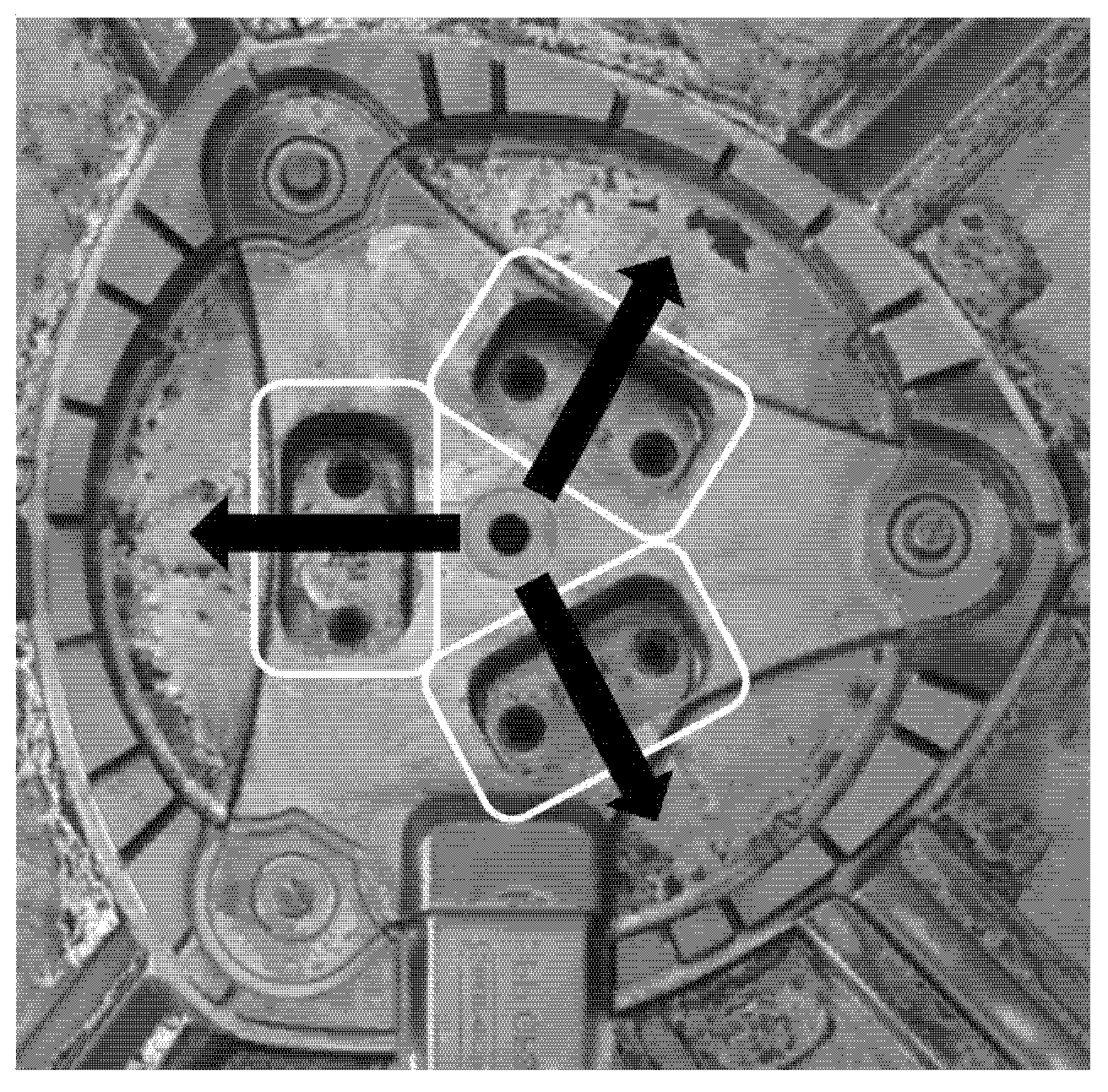
As previously referred, the main objective of this work is to study the wear resistance of the coatings when applied in injection mould cavities used to produce glass fibre–reinforced plastic parts for automotive industry. Thus, an industrial mould often used for the production of radiator plastic fans was selected and three cavities symmetrically distributed and crossing the runners were machined into the mould allowing that samples surface fits well on the cavity due to the progressive section of the sample and cavity and allow that the sample exposed face is in the same plane of the mould surface in this area. The cavities were located centred on each plastic runner as depicted in
Figure 3. During the injection cycle, glass fibre–reinforced plastic flows by the main feed channel (sprue) at the centre, being then split in three different ways. Arrows included in this figure intend to show the three directions of the plastic flow towards the secondary plastic feed channels (runners). These arrows were drawn over the sample cavities specially produced on the mould. Inserts were located in a turbulent area, in order to maximise the abrasive effect of the glass fibres, due to a previous quick flow direction shift. The composite used in the process is polypropylene reinforced with 30 wt % glass fibres and 9 × 10
4 injection cycles were performed allowing study the wear behaviour of the coating. It is well-known that, in these conditions, uncoated AISI P20 tool steel presents eye-visible severe wear scars. In these conditions, mould needs a complicate and expensive maintenance process, involving production breaks, accurate production plans and smart stock management or delivery delays. For this purpose, a KRAUSS MAFFEI injection machine (Krauss-Maffei Wegmann GmbH & Co. KG, Munich, Germany) was used presenting 5000 kN clamp force and inner initial pressure of 140 bar on the mould. The injection speed used was 50 m·s
−1 and injection temperature was about 250 °C.
3. Results and Discussion
The chemical composition of the films was evaluated using electron-probe microanalysis. The results can be seen in
Table 2, showing that the compositions are in line with the targets and gases used in the deposition process and fulfil the initial expectations. The coatings’ thickness was assessed by SEM, leading to the values listed in
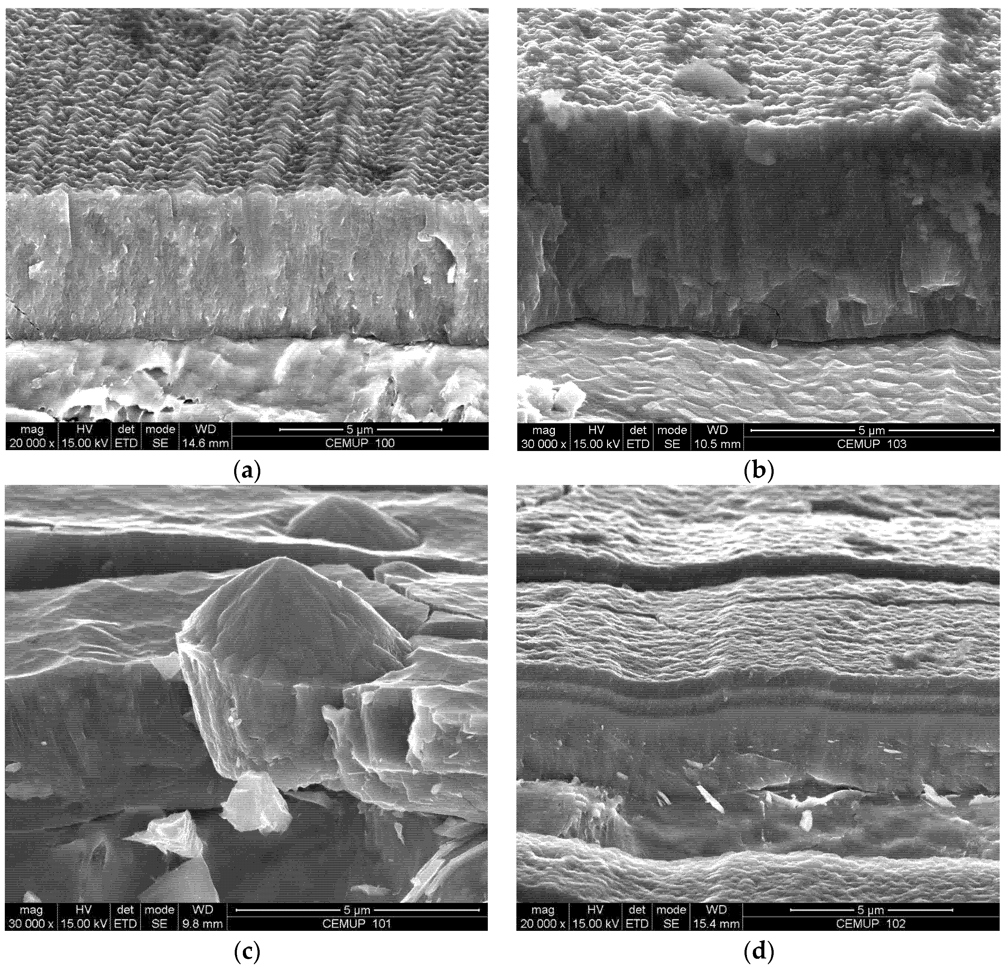
Table 3, in the range of 3.5 to 4.5 µm, as desired, having been controlled by both the deposition rate and time. The morphology of the coatings was analysed by SEM as well, denoting that the films tend to follow the substrate topography, keeping the thickness approximately constant along the surface. The coatings’ surface was relatively smooth, as shown in
Figure 4, as expected when the films are produced using the magnetron sputtering technique. The nanostructured coating shown in
Figure 4d corresponded to different CrCN phases, one of them more carbon-rich than the other, which was obtained providing C
2H
2 periodically and controlled over time. However, the TiAlSiN film presented some aggregates at the surface, which can originate from tribological problems, both through the generation of preferred sites for crack nucleation and problems related to the release of these large particles in contact the counter-face. The roughness was evaluated by profilometry and yields to confirm that Ra values were in the range of 0.033 µm to 0.061 µm for all coatings. The
Ra values obtained by the AFM evaluation were slightly different, varying in the range of 0.028 µm to 0.053 µm, this difference being mainly attributed to the lower area of analysis. The values obtained are in line with the requirements usually defined for inner mould surfaces for the plastic injection moulding of non-visible automotive parts, such as the case studied in this work. The micro-hardness was measured using different techniques due to the low thickness of the CrN/CrCN/DLC final layers, revealing that the hardest coating was the CrN/TiAlCrSiN coating and the softest was the CrN/CrCN/DLC coating. Taking into account the curves’ load/depth of displacement of the indenter generated by the micro-hardness equipment, Young’s modulus was also assessed, allowing us to compute the reduced Young’s modulus, the values of which are shown in
Table 3, which allowed us to compute the values of the H
3/E
r2 ratio, a good indicator for the coatings’ resistance to plastic deformation. In this case, the best and worst plastic deformation resistance was presented by CrN/TiAlCrSiN and CrN/CrCN/DLC coatings, respectively. Believing just in the hardness values obtained, the CrN/TiAlCrSiN coating would present the best wear resistance due to it having highest value in the range of coatings tested in this work.
Adhesion tests were carried out using two different techniques: scratch tests and indentation tests, as described in the Experimental Section. The scratches produced during the tests were carefully analysed by optical microscopy and allowed us to observe some typical phenomena usually occurring in these tests, namely conformal cracking (TiAlSiN) plus lateral chipping (TiAlN), coating delamination in the scratch channel and lateral cracking (CrN/TiAlCrSiN). In general, the critical loads that caused the coatings’ failure in these tests were below the expectations. These values varied between 20 and 25 N, considering the two orthogonal directions selected. Films with similar compositions usually present critical loads for adhesion or cohesion failure at about 70 or even 75 N. Thus, the indentation technique was also used in order to cross the results and to guarantee that the coatings’ adhesion was enough to continue to the wear tests. Except the CrN/CrCN/DLC coating, all coatings were subject to indentation tests using 30 and 100 kgf as described in the Experimental Section and subsequently observed by optical microscopy, allowing us to observe that indentation borders presented mainly a cracking pattern of small radial cracks in all the films observed. Despite some reports that CrN-based coatings present delamination in the borders of the indentation [
26], no delaminations were observed in the samples used in this work. Thus, all the films were considered suitable for wear tests.
The micro-abrasion tests were carried out following the conditions already mentioned in the Experimental Section. Due to the low thickness of the films, after some ball revolutions in the micro-abrasion tests, the coating was consumed by abrasion and just the film border prevented greater wear [
27]. Thus, in these cases, it was necessary to measure the inner and outer diameter of the crater, which corresponded to the substrate and coating-resistant area. In order to analyse the coatings’ behaviour, just the removed material corresponding to the coating was considered for calculations (c—coating). The results showed that the wear coefficient (
kc) was the smallest for the TiAlN coating while it was the greatest for the CrN/TiAlCrSiN coating, corresponding to the better wear resistance (
k−1) of the TiAlN coating, which also presented a relatively low reduced Young’s modulus. The results summary of these tests can be seen in
Table 4.
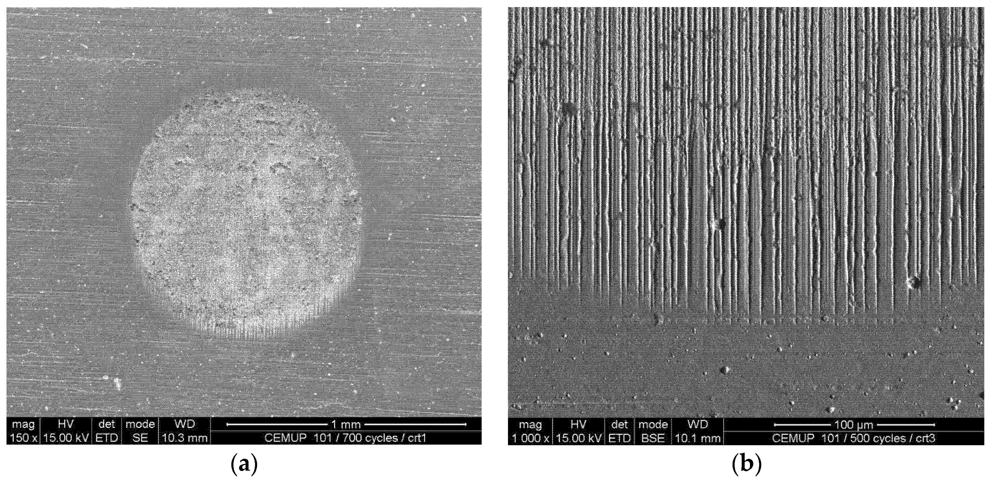
Figure 5 depicts the usual shape of each crater with the typical border corresponding to the film’s resistant thickness, whereas the inner area corresponds to the substrate that was in contact with the ball and the abrasive slurry after coating perforation.
Figure 5b shows the typical way out border of the slurry, displaying how the abrasive particles scratched the coating into the crater, reducing this effect as the ball left the contact area of the sample. As shown in
Table 4, regarding just the micro-abrasion tests, the best wear behaviour was shown by the CrN/TiAlCrSiN coating, allowing a useful lifespan 65.5 times greater than the uncoated substrate. However, these tests should be considered comparative, using the wear resistance already obtained and computed in similar conditions when testing other coatings. The wear phenomena expected in the plastic injection moulding process are quite different, just because the difference in the hardness between materials and the density of abrasive particles present in the contact are also quite different.
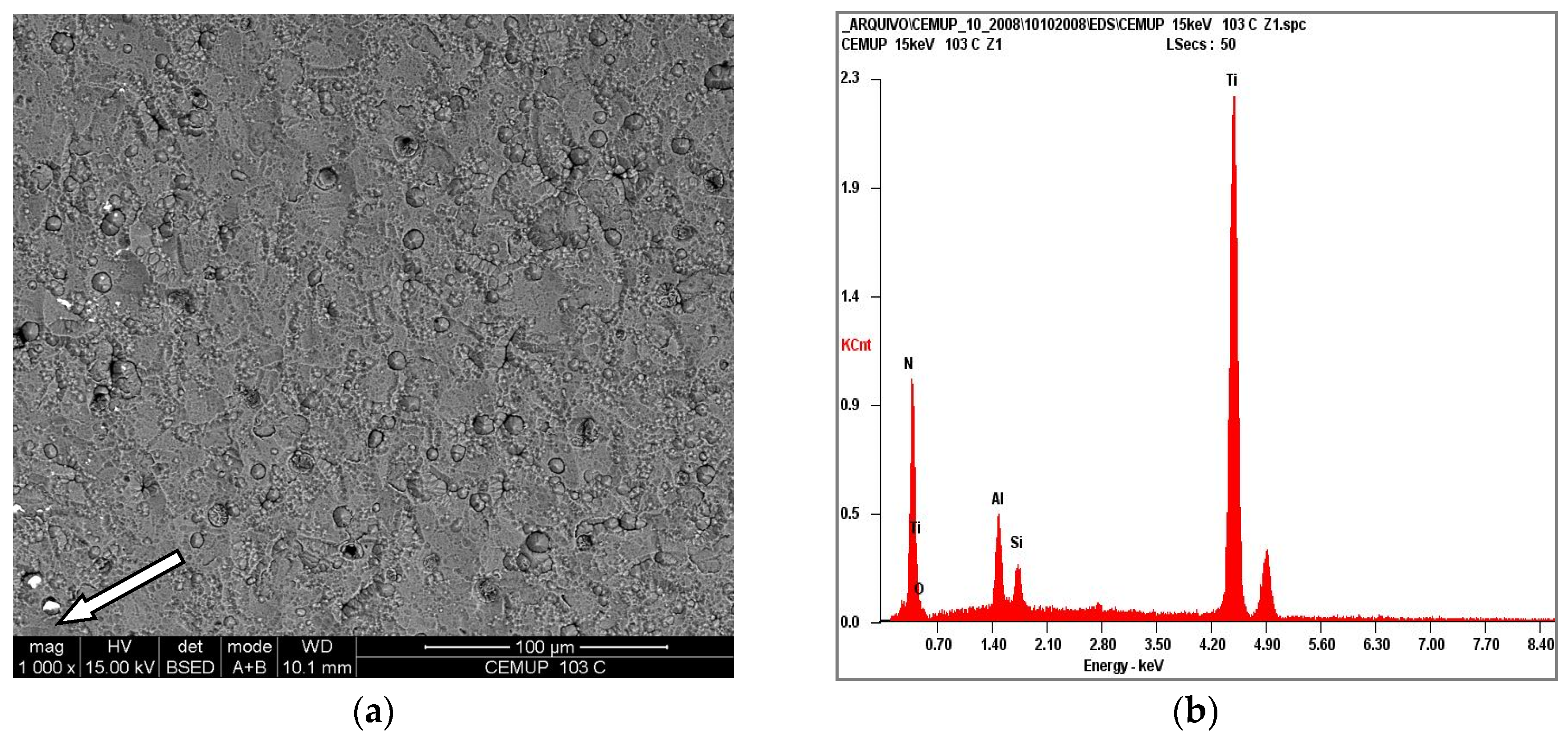
Assuming that industrial tests could lead to significantly different results, the industrial tests were performed by inserting three different samples into cavities previously machined in the mould and adjusting them in order to keep their surface on the same plane of the remaining inner surface of the mould. Thus, the reinforced plastic could flow through the feed channels, tangentially abrading the mould and sample surface during its motion along the feed channels, with some turbulence caused by the directional flow shift of the reinforced plastic close to the sample’s position. Each sample was provided with a different coating, allowing us to test three different coatings in each setup. The injection conditions and reinforced plastic properties had already been previously announced. After 9 × 10
4 injection cycles, the lowest volume of the coating removed by abrasion and adhesion was achieved by the hardest multilayer coating, CrN/TiAlCrSiN. The results in this test were obtained by analysing the material removed from the surface due to the glass fibres’ abrasion during the injection cycle runs, as can be seen in
Figure 6. The surface of the coatings was analysed by SEM and wear scars or detachments were identified by computed with homemade software (PAQI) which allows us to determine the percentage of the coating area removed. Complementary EDS tests were also conducted in order to verify the absence of coating in those areas.
The thickness of the coatings was already analysed by profilometry, based on the surface of the samples not exposed to the plastic flow. The results can be seen in
Table 5.
Regarding these last results, the hardness seems to play an important role in the wear behavior of the multilayered coating when submitted to the injection of reinforced polypropylene. On the other hand, TiAlN presented the best wear behavior when submitted to micro-abrasion tests, even presenting a lower hardness than the CrN/TiAlCrSiN coating and also a relatively low H3/E2 ratio, showing low resistance to plastic deformation. Thus, this work allowed us to observe that micro-abrasion tests cannot be used to predict the coating lifespan when applied to mould cavities for the reinforced plastic injection moulding process.


