Article

Microstructural Changes of Al Hot-Dipped P91 Steel during High-Temperature Oxidation

1
School of Advanced Materials Science and Engineering, Sungkyunkwan University, Suwon 16419, Korea
2
Department of Mechanical Engineering, Mehran University of Engineering and Technology, SZAB Campus, Khairpur Mir’s 66020, Pakistan
*
Author to whom correspondence should be addressed.
Coatings 2017, 7(2), 31; https://doi.org/10.3390/coatings7020031
Submission received: 30 December 2016 / Revised: 6 February 2017 / Accepted: 13 February 2017 / Published: 17 February 2017

Abstract

:
The 9Cr-1Mo steel (ASTM P91) was hot-dip aluminized, and its microstructural changes during oxidation were studied. Before oxidation, the coating consisted of (Al-rich topcoat containing a small amount of Al5Fe2 and Al13Fe4)/(Al13Fe4-rich, Al13Fe4-containing alloy layer)/(Al5Fe2 alloy layer containing a small amount of Al9Cr4 precipitates), from the surface. During oxidation at 700–900 °C for 20–100 h, Al diffused inward and the substrate elements migrated outward to broaden and soften the coating, and also to transform (high Al)-Fe intermetallics to (low Al)-Fe intermetallics. The phases in the coating progressively transformed during oxidation as follows; (Al-rich topcoat)/(Al5Fe2–rich, Al13Fe4-containing alloy layer)/(Al5Fe2 alloy layer)→(α-Al2O3 scale)/(Al13Fe4–rich, Al5Fe2-containing layer)/(Al5Fe2 layer)/(AlFe interlayer)→(α-Al2O3 scale)/(AlFe–rich, Al5Fe2-containing layer)/(AlFe layer)/(AlFe3 layer))→((α-Al2O3, Fe2O3)-mixed scale)/(AlFe3 layer)/(Fe(Al) layer) from the surface. As the oxidation progressed, the scale changed from α-Al2O3 to the (α-Al2O3, Fe2O3)-mixture, which provided the necessary oxidation resistance.

1. Introduction

The 9Cr-1Mo ferritic steel (ASTM P91) was developed to replace low-alloy ferritic steels such as 1Cr-0.5Mo (ASTM P12) and 2.25Cr-1Mo (ASTM P22). It has advantageously lower thermal expansion coefficients, better mechanical properties, and high-temperature corrosion resistance compared to low-alloy ferritic steels. It is also less expensive than austenitic stainless steels. However, the main limitation to its wide industrial application is its fast degradation at high temperatures, because scales consisting of iron oxides form due to the low Cr concentration. The critical concentration needed to form the protective Cr2O3 surface scale is about 10–12.5 wt % Cr for Fe-Cr alloys [1]. When 9Cr-1Mo steels oxidized at 650 °C, the scale composed of Fe3O4, Fe2O3, and (Fe,Cr)3O4 formed [2], restricting their application above 650 °C [3]. Hence, the high-temperature oxidation resistance of 9Cr-1Mo steels needs to be improved through surface modification techniques. Aluminum hot-dipping is a simple, cost-effective coating technique that could form the compact, slow growing, protective alumina scale in reaction with oxygen at high temperatures [4,5,6,7,8,9,10,11,12,13,14,15]. It also improves the surface hardness by forming Al-Fe intermetallics [5,7,9,13]. Diverse aluminized coatings have been obtained by hot-dipping carbon steels in Al [5,7,12,13] and Al-Si molten baths [5,9], 5Cr-0.5Mo steels in Al [14] and Al-Si molten baths [16], and 9Cr-1Mo steels in Al-Si [17] and Al-Si-Mg molten baths [15]. They significantly enhanced the high-temperature oxidation and corrosion resistance of the underlying steels through forming α-Al2O3 [5,7,9,12,13,14,17,18], α-Al2O3 + FeAl [6,15], and FeAl [16] layers. However, microstructural changes during high-temperature oxidation and the oxidation resistance of 9Cr-1Mo steels that were hot-dipped in the Al molten bath have not been adequately investigated before. The aim of this study was to hot-dip aluminize the 9Cr-1Mo steel in order to form the Al topcoat and Al-Fe alloy layer, and examine the oxidation behavior at high temperatures. Also, the oxidation behavior of the uncoated 9Cr-1Mo steel was investigated for comparison purposes. Particular emphasis was placed on the coating thickness, coating microstructure, coating phases, and the scales that formed on the coating during oxidation at high temperatures. These characteristics vary sensitively, depending on the Al hot-dipping temperature, time, bath composition, and the composition of the substrate. The importance and influence of AlxFey phases on the performance of coating is a distinct area of discussion. Our study will only be focused towards the characterization of Al hot-dipped coatings on P91 steel in order to evaluate the microstructural changes during high-temperature oxidation.

2. Materials and Methods

A P91 steel plate (80 × 30 × 3 mm3 in size) with a nominal composition of Fe-9Cr-1Mo-0.45Mn-0.4Si-0.2V-0.08Nb-0.1C (wt %) was selected as the substrate. Both sides of the steel plate were ground to 1000 grit SiC finish, cleaned in 10 vol % HCl solution to remove the surface oxide, subjected to the liquid flux treatment with 20 vol % (KCl + AlF3 in 4:1 weight ratio) solution, and dipped in molten Al for 5 min at 800 °C, on top of which a solid flux (KCl + NaCl + AlF3 in 2:2:1 weight ratio) was spread to protect molten Al from oxidation. After hot dipping, the aluminized P91 steel plate was pulled out, cooled to room temperature, cleaned using 5 vol % HNO3 solution to remove the flux on the surface, and then oxidized at 700, 800, and 900 °C for up to 100 h in air. When oxidized at 900 °C for 100 h, the uncoated steel oxidized fast, and the enhanced counterdiffusion in the coated steel made the coating and substrate somewhat ambiguous. Therefore, the time at the 900 °C condition was optimized to 20 h to show the microstructural changes of Al hot-dipped P91 steel during high-temperature oxidation. The uncoated sample was also oxidized at similar conditions for comparison purposes and in order to evaluate the diffusion mechanism using marker testing. The samples were inspected using an optical microscope (OM; Leica DM2700, Leica Microsystems, Heerbrugg, Switzerland), a field-emission scanning electron microscope (SEM; JSM-7600 F, Jeol, Tokyo, Japan) equipped with an energy dispersive spectrometer (EDS; XMAX, Oxford INCA Energy, Abingdon, UK), an electron probe microanalyzer (EPMA; Shimadzu, EPMA 1600, Kyoto, Japan), and a high-power X-ray diffractometer (HP-XRD; Bruker D8 Advance, Bruker Corporation, Karlsruhe, Germany) with Cu-Kα radiation at 40 kV and 300 mA. The microstructures of the aluminized layer and the steel substrate were etched for 10 s using Keller’s reagent and Vilella’s reagent, respectively. Vickers microhardness was measured using a microhardness tester (MVK-H2, Mitutoyo Corporation, Kanagawa, Japan) at a load of 100 g with an indentation time of 5 s. Hereafter, the compositions are denoted in atomic percentages (%), unless otherwise stated.

3. Results and Discussion
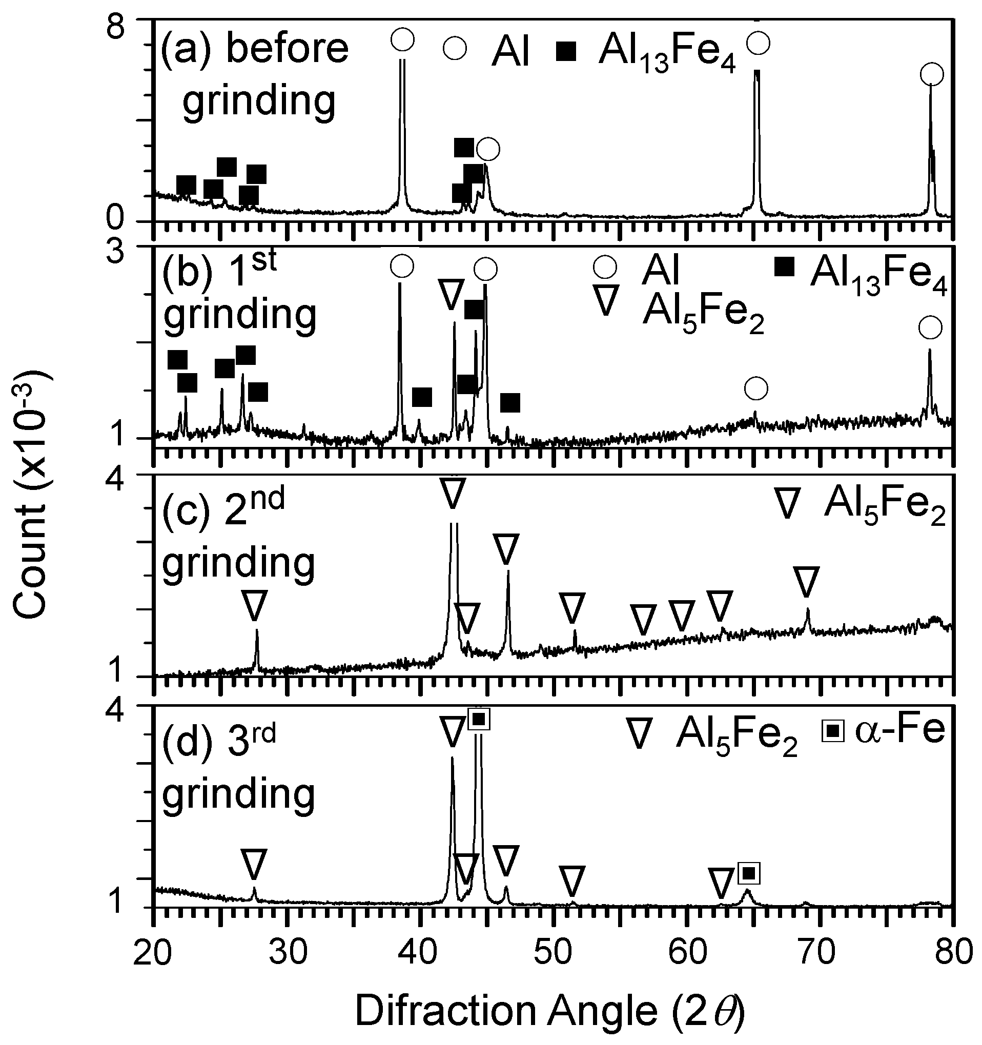
Figure 1 and Figure 2 show XRD/SEM/EDS analytical results of the Al hot-dipped P91 steel. To identify the coating phases, the Al-coating was successively ground off from the surface using the abrasive paper, and X-ray analysis was performed as follows. From the surface, [Al(s), Al13Fe4(w)] (Figure 1a), [Al(s), Al13Fe4(m), Al5Fe2(m)] (Figure 1b), Al5Fe2(s) (Figure 1c), and [α-Fe(s), Al5Fe2(m)] (
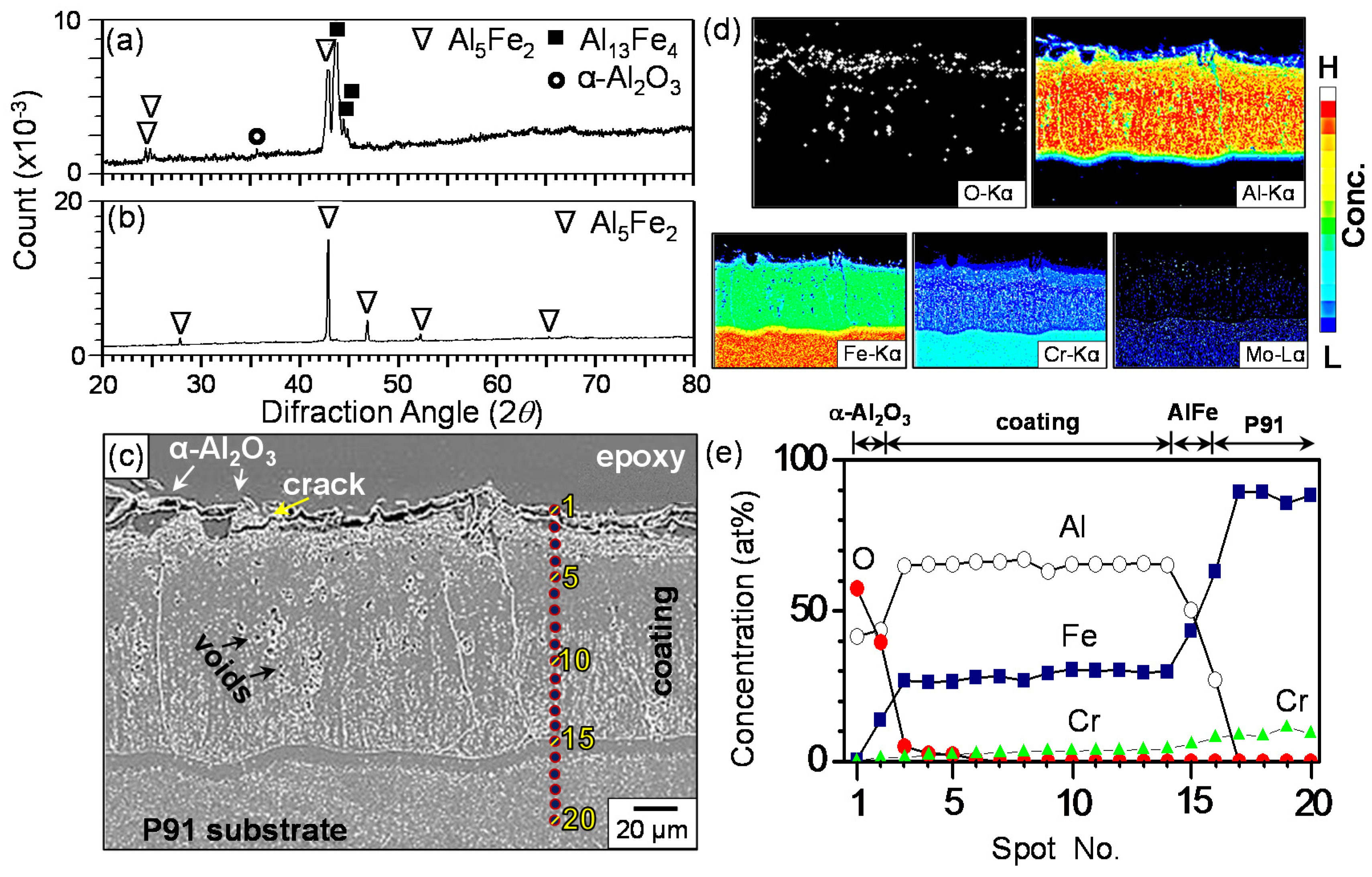
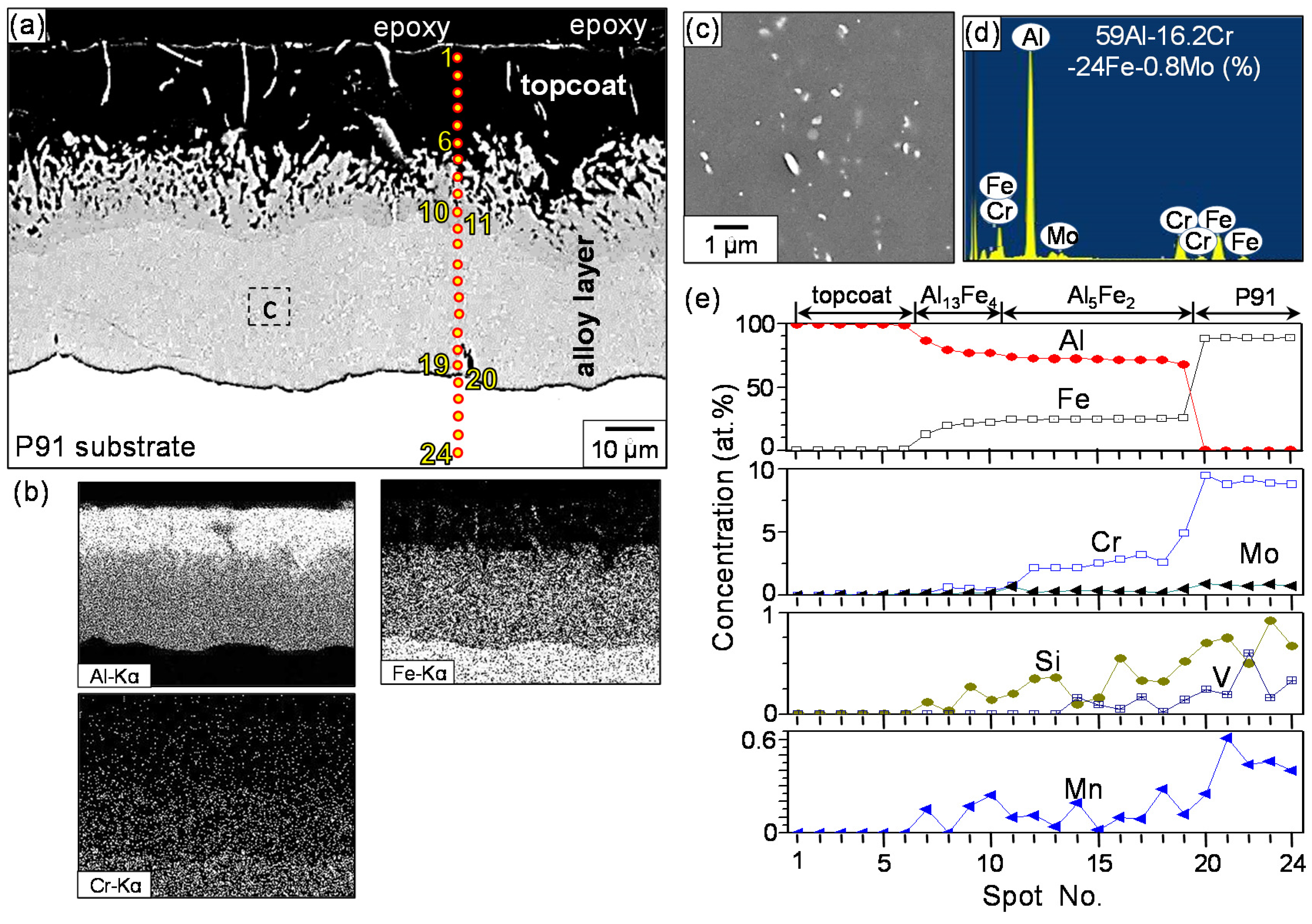
Figure 1d) phases were detected. Here, (s), (m), and (w) denote that the intensity of the diffraction patterns were strong, medium, and weak, respectively. Hot dipping formed a ~20 μm-thick topcoat (spots 1–6), ~15 μm-thick transient alloy layer (spots 7–10), and ~35 μm-thick underlying alloy layer (spots 11–19) on the steel substrate (spots 20–24) (Figure 2a). The topcoat (spots 1–6) consisted primarily of Al with a small amount of Al13Fe4 (in the whole topcoat) and Al5Fe2 (at the lower part of the topcoat). The presence of Al13Fe4 and the absence of Al5Fe2 at the upper part of the topcoat is plausible, considering the Al concentration gradient during hot dipping (Figure 1a,b). The alloy layer consisted primarily of Al13Fe4 (spots 7–10) and Al5Fe2 (spots 11–19). Al5Fe2 in Figure 1b–d, and α-Fe in Figure 1d belonged to the alloy layer and the substrate, respectively. White strings inside the topcoat (spots 1–6) were Al-Fe intermetallics (see Al and Fe maps of Figure 2b), which were found to be Al13Fe4 and Al5Fe2 embedded in the Al-rich topcoat (see Figure 1a,b). While Al diffused inwards, substrate elements such as Fe and Cr diffused outwards according to the concentration gradient (Figure 2b). Orthorhombic Al5Fe2 had 30% vacancies along the c-axis, through which the counter diffusion of Al and Fe occurred rapidly [4,8,13,14,18]. Hence, the Al5Fe2 layer (spots 11–19) was thicker than the Al13Fe4 layer (spots 7–10 inside the alloy layer) [10,11]. On the other hand, in the case of low-alloyed carbon steels, the characteristic finger- or tongue-like morphology that oriented along the c-axis of Al5Fe2 generally developed at the coating/substrate interface [4,5,6,9,10,12,13]. Such a morphology however was not noticeable around the spots 19–20 shown in Figure 2a, because vacancies in Al5Fe2 were occupied more by substrate elements in the current high-alloyed Cr steel, resulting in the flattening of the coating/substrate interface and narrowing of the alloy layer. The major substrate element, Fe, diffused outward through the alloy layer into the topcoat (see the Fe map of Figure 2b), and reacted with the molten aluminum to form Al13Fe4 and Al5Fe2 strings (see spots 1–6 in Figure 2a). The enlarged image of the alloy layer revealed scattered, white particles in the alloy layer (Figure 2c). Figure 2d indicates that white particles were probably Al9Cr4 precipitates that could dissolve up to 32.5% Fe [19]. The counterdiffusion of Al and the substrate elements due to the concentration gradients that were generated during hot dipping resulted in the formation of the topcoat, the Al13Fe4 layer, and the Al5Fe2 layer, as shown in Figure 2e. Moving from spot 19 towards the surface, the concentration of Cr decreased from 4.9% (spot 19) to 0.1% (spot 3), whilst the other alloying elements such as Mo, Mn, Si, and V decreased from 0.5% (spot 19) to 0% (spot 3) (Figure 2e). The average composition of spots 1–2 was 99.7%Al-0.3%Fe, indicating the dissolution of Fe in Al and/or the presence of a small amount of Al13Fe4 in the Al-rich topcoat.
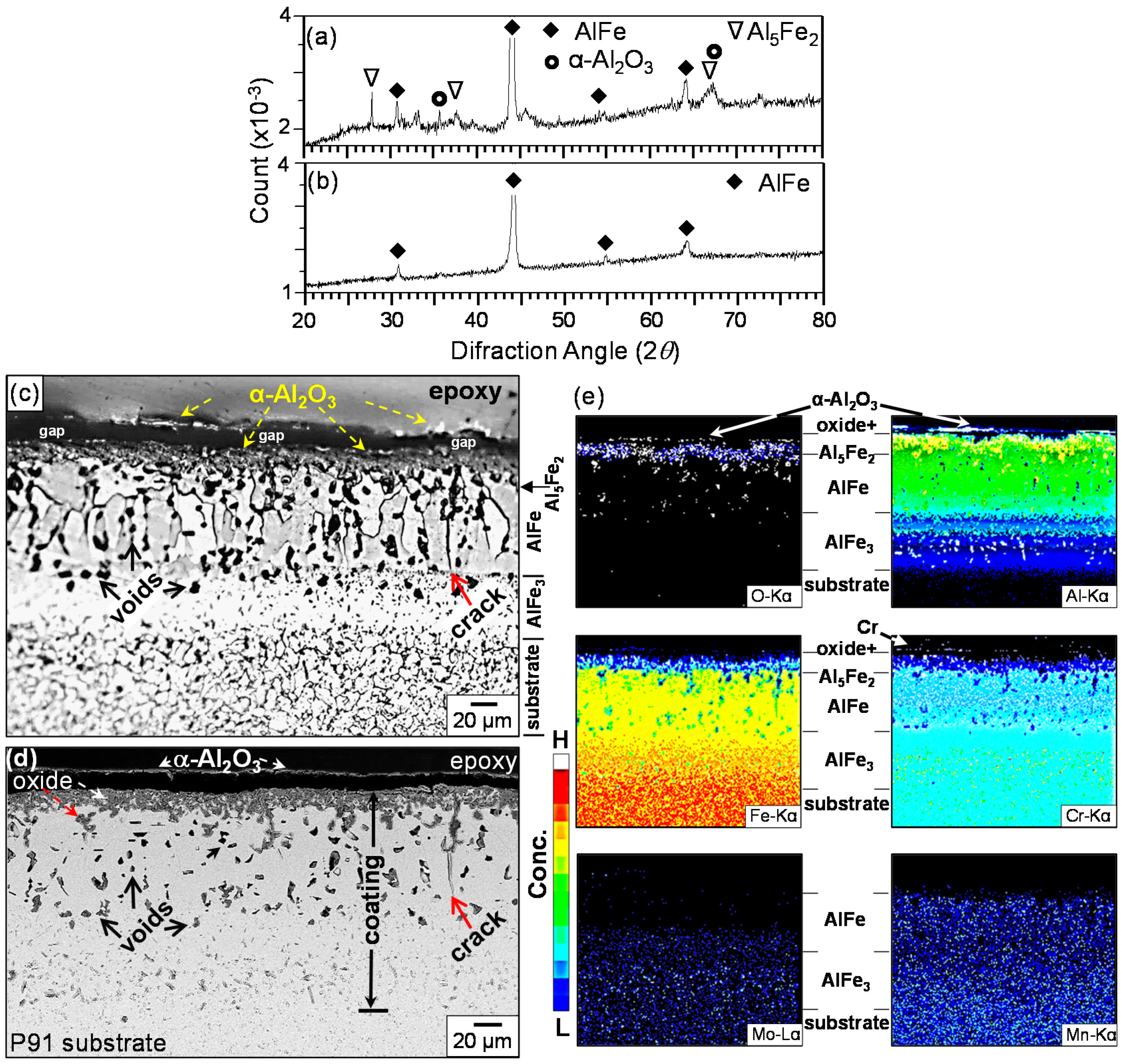
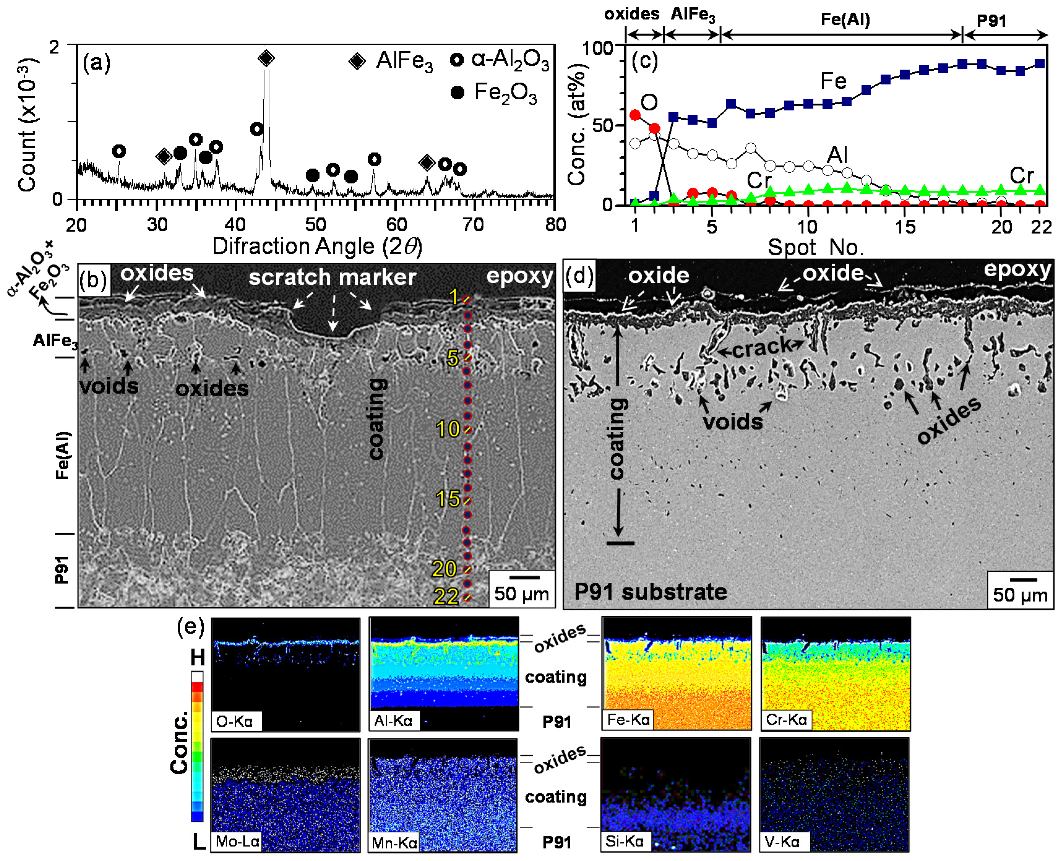
Figure 3 shows XRD/EPMA/EDS results of the Al hot-dipped P91 steel after oxidation at 700 °C for 100 h. Aluminum in the topcoat either oxidized to the α-Al2O3 scale or transformed to Al-Fe intermetallics through the reaction with outwardly diffusing Fe atoms, as shown in Figure 3a. Here, the α-Al2O3 scale formed above the (Al13Fe4, Al5Fe2)-mixed layer that originated from the Al-rich topcoat. The alloy layer that consisted of Al13Fe4 and Al5Fe2 (Figure 2a) became only Al5Fe2 due to the counterdiffusion of Al and the substrate elements during heating (Figure 3b). Counterdiffusion increased the coating thickness from 70 μm (spots 1–19 in Figure 2a) to 125 μm (spots 3–16 in Figure 3c). Figure 2d shows EPMA maps of the thin α-Al2O3 surface scale (spots 1–2 in Figure 3c), the coating that consisted primarily of Al5Fe2 (spots 3–16 in Figure 3c), and the steel substrate (spots 16–20 in Figure 3c). The α-Al2O3 oxide was susceptible to spallation owing to its mismatch of the thermal expansion coefficient with the underlying coating (see spots 1–2 in Figure 3c). Hence, the α-Al2O3 peak was weak in Figure 3a. Unequal mass flow and volume change due to the transformation of the topcoat and the alloy layer to Al13Fe4 and Al5Fe2 generated cracks and numerous voids in the coating [5,6,7,9,14,15] (Figure 3c). The loosely adherent α-Al2O3 scale was partially broken (see the Al map of Figure 3d). In Figure 3d, the inwardly diffusing Al diluted the concentration of Fe, Cr, and Mo in the coating. A small amount of oxygen dissolved in the coating. In Figure 3e, the α-Al2O3 oxide (spots 1–2) formed on the Al-Fe coating that consisted primarily of Al5Fe2 (spots 3–14). Around spot 3, Al13Fe4 coexisted with Al5Fe2 (see Figure 3a,e). This was plausible considering the Al concentration gradient. AlFe, which can exist in the Al concentration range of 23.3%–55%, existed at the coating/substrate interface (see spot 15 in Figure 1d). Unlike the ductile AlFe phase, Al13Fe4 and Al5Fe2 were brittle. This is another reason for the breakage and subsequent spallation of the oxide scale. The concentration of dissolved Cr decreased gradually from 4.2% (spot 14) to 0.1% (spot 1). Since Al (m.p. = 660 °C) can diffuse rapidly and readily oxidize due to its high oxygen affinity, the transformation of the topcoat and the alloy layer to the α-Al2O3 scale and Al-Fe intermetallics seemed to occur quickly.
The optical microstructure of Figure 3c is shown in Figure 4. The α-Al2O3 scale consisted of fine, round grains, because it grew slowly. Most of the coating consisted of numerous grains that elongated along the counterdiffusion direction of the Al and substrate elements. Particularly, Al5Fe2 grew fast perpendicular to the sample surface [4]. AlFe grains were largely square (see spot 15 in Figure 3c and Figure 4). The area immediately below the AlFe layer was bright, because rounding occurred during polishing due to the hardness difference between the AlFe intermetallic and the substrate.
Figure 5 shows XRD/OM/EPMA results of the Al hot-dipped P91 steel after oxidation at 800 °C for 100 h. Weak α-Al2O3 peaks were detected in Figure 5a due to the slow growth rate and poor adherence of the α-Al2O3 scale. The coating just below the α-Al2O3 scale consisted of AlFe as the major phase and Al5Fe2 as the minor phase (Figure 5a). However, most of the coating consisted of AlFe (Figure 5b). In Figure 3, the coating just below the scale consisted of Al13Fe4 as the major phase and Al5Fe2 as the minor phase, while most of the coating consisted of Al5Fe2. Thus, it is seen that the increment of the heating temperature from 700 to 800 °C led to the formation of Al5Fe2 instead of Al13Fe4, and AlFe instead of Al5Fe2 through the enhanced counterdiffusion of the Al and substrate elements. Figure 5c shows a ~4 μm-thick α-Al2O3 layer, ~20 μm-thick Al5Fe2-rich layer, ~70 μm-thick AlFe layer, ~65 μm-thick newly formed transient coating, and the substrate that consisted of equiaxed grains. Elongated Al5Fe2 grains shown in Figure 4 grew to coarse, columnar AlFe grains in Figure 5c. The optical image shown in Figure 5c shows the α-Al2O3 scale either detached or adherent, Al5Fe2-rich layer, AlFe layer, transient coating, and the substrate. The Kirkendall effect and the Al-Fe phase transformation generated many voids (dark spots in the coating) and some cracks (Figure 5c,d). In Figure 5e, Al diffused inwardly to the bottom of the transient coating, which was believed to consist of AlFe3, because AlFe3 could form between AlFe and α-Fe according to the Al-Fe binary phase diagram. In Figure 5e, the major alloying element, Cr, diffused up to the surface to dissolve in the α-Al2O3 layer. The second major alloying element, Mo, was denuded at the upper part of the coating owing to its small solubility in AlFe [20]. The third major alloying element, Mn, was present in the whole coating.
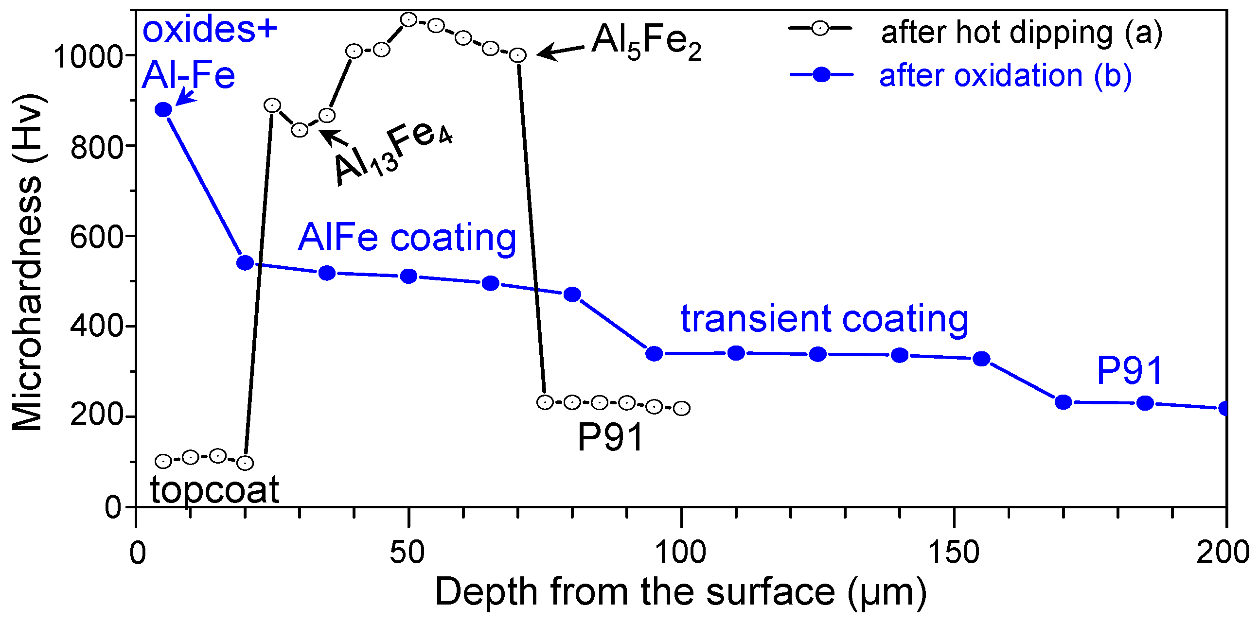
The Vickers microhardness of the sample, outlined in Figure 2 and Figure 5, is displayed in Figure 6. Before heating, the average microhardness of the Al-rich topcoat, Al13Fe4 layer, Al5Fe2 layer, and substrate was 105, 863, 1031, and 228 Hv, respectively. The lowest and highest microhardness was similarly reported in the Al-topcoat and Al5Fe2-alloy layer, respectively [4,13]. The Al-rich topcoat disappeared after oxidation at 800 °C for 100 h in air [13]. Heating broadened and softened the alloy layer so that the average microhardness of the (oxides, Al-Fe)-mixed layer, AlFe layer, AlFe3 transient layer, and the substrate became 879, 507, 336, and 227 Hv, respectively. The increment of the surface hardness of the hot-dip aluminized P91 steel improves the wear resistance and thereby the performance of structural components [13].
Figure 7 shows the XRD/SEM/EDS/EPMA results of the Al hot-dipped P91 steel after oxidation at 900 °C for 20 h. In Figure 7a, α-Al2O3(m) and Fe2O3(w) formed on the AlFe3(s) coating. From Figure 7b,c, it is seen that the ~35 μm-thick (α-Al2O3, Fe2O3)-mixed oxide layer either detached or adherent (spots 1–2), ~90 μm-thick AlFe3 layer (spots 3–5), and the ~255 μm-thick Fe(Al) coating (spots 6–18; α-Fe layer dissolved with some Al) existed on the substrate (spots 19–22). Iron diffused outwardly to form Fe2O3 (Figure 7a), whose amount was smaller than that of α-Al2O3 (spots 1–2 in Figure 7c). Moving from the oxide layer through the AlFe3/Fe(Al) coating to the substrate, the concentration of Al and oxygen decreased, while those of Fe and Cr increased (Figure 7c). In Figure 7b, a scratch was shown at the surface. It was made using a knife prior to oxidation in order to study the oxidation mechanism of the hot dipped sample. If the scratch was buried by oxides after oxidation, the oxidation had to be controlled by the outward diffusion of substrate elements. However, this was not observed in Figure 7b, indicating that no significant outward diffusion of substrate elements to form the oxide scale had occurred. In Figure 7d, internal oxides, voids, and cracks were seen in the AlFe3/Fe(Al) coating. Voids in the AlFe3 layer were coarser than those in the Fe(Al) layer, because the inward transport of Al from the AlFe3 coating into the Fe(Al) coating occurred faster than the outward migration of substrate elements such as Fe, Cr, Mo, Mn, Si, and V towards the surface [6] (Figure 7e). The substrate was void-free (Figure 7d). Figure 7e indicates that substrate elements diffused up to the surface, while Al diffused inwardly down to the Fe(Al) layer. In Figure 5c, the ~4 μm-thick α-Al2O3 layer, ~20 μm-thick Al5Fe2-rich layer, ~70 μm-thick AlFe layer, and ~65 μm-thick transient AlFe3 layer existed on the substrate. When compared to Figure 5c, the following observations were noticeable due to the enhanced reaction rate and counterdiffusion at 900 °C. The (Al5Fe2-rich layer)/(AlFe layer) (Figure 5c) changed to the AlFe3 coating (Figure 7c). The transient AlFe3 layer (Figure 5c) changed to the Fe(Al) coating (Figure 7c). Grains in the Fe(Al) coating were much more coarse, and columnar than those in the transient AlFe3 layer, confirming the increased growth rate of grains along the direction of counterdiffusion (Figure 7b). The α-Al2O3-rich scale that had some Fe2O3 grew predominantly inwards through the cracks (Figure 6d,e). The densities of Al13Fe4, Al5Fe2, AlFe, and AlFe3 were 3.849, 3.96, 5.67, and 6.57 g∙cm−3, respectively. When hard, brittle Al13Fe4 and Al5Fe2 layers, viz. low density phases, transformed to soft, ductile AlFe and AlFe3 layers, viz. high density phases, the volume shrank, and therefore cracks were generated [14,15].
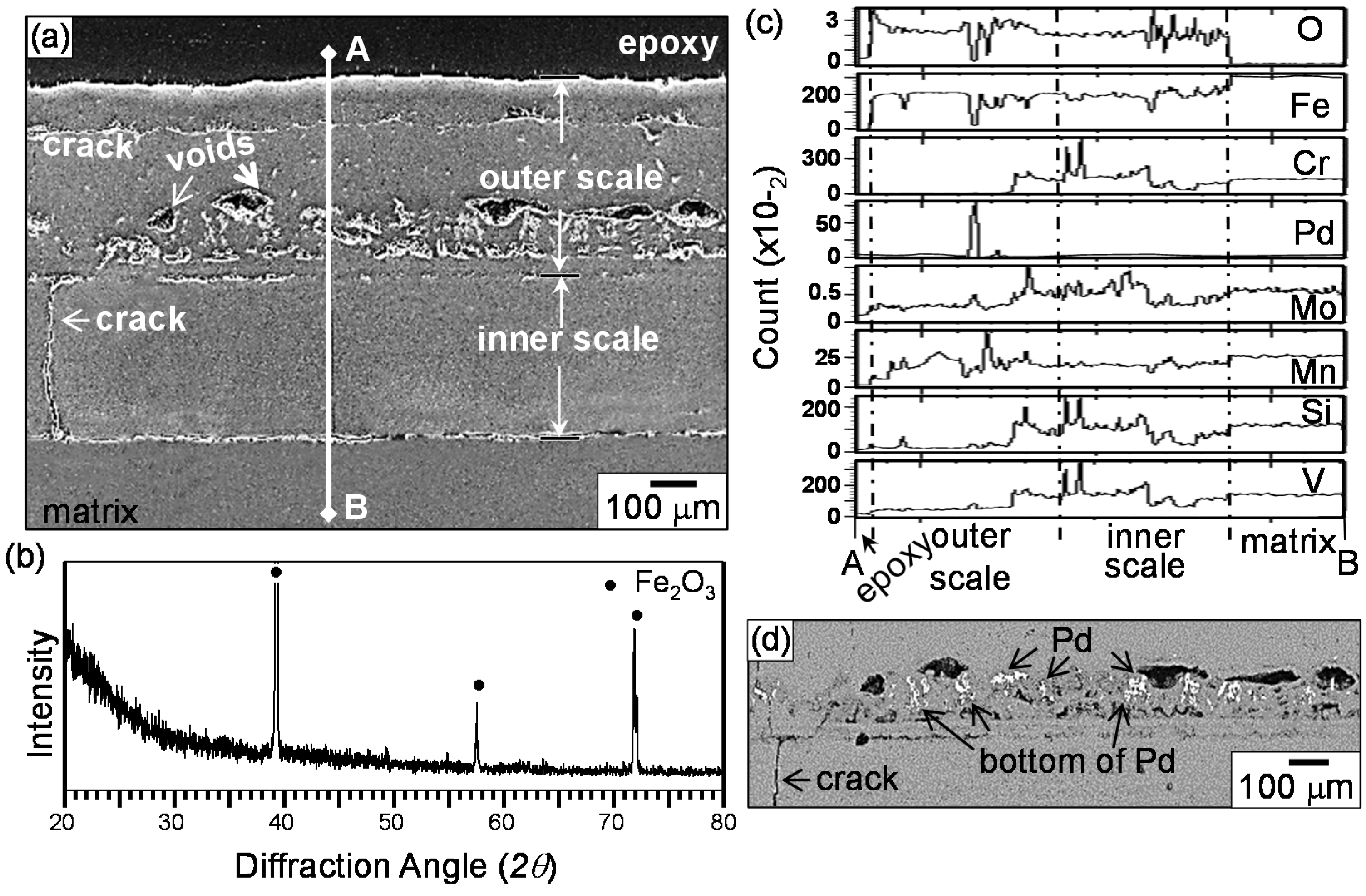
The beneficial effect of Al hot-dipping in increasing the oxidation resistance of P91 steel is clearly seen from the comparison of Figure 7 and Figure 8. The uncoated P91 steel formed an outer 425 μm-thick oxide scale and an inner 360 μm-thick oxide scale (Figure 8a). Cracks and voids were generated due to the increased thermal and growth stresses aroused in the thick scale, which deteriorated the scale adherence. The outer scale consisted primarily of Fe2O3 (Figure 8b), where a small amount of alloying elements such as Cr, Mo, Mn, Si, and V dissolved (Figure 8c). All the matrix elements such as Fe, Cr, Mo, Mn, and Si were found in the inner scale (Figure 8c). In Figure 8d, white spots were Pd particles that were sprayed on the surface prior to oxidation in order to study the oxidation mechanism of P91 steel. The bottom of the Pd particles corresponded to the original sample surface. The Pd marker experiment indicated that the outer scale formed primarily by the outward diffusion of substrate elements, while the inner scale formed by the inward transport of oxygen. When cations diffused outwardly, they pushed the Pd particles upward, which was responsible for the Pd signal in the middle of the outer scale (Figure 8c) and the Pd particles above the interface of the outer/inner oxide scale (Figure 8d). In the case of coated steel, the selective oxidation of Al led to the formation of the Al2O3-rich scale, which effectively protected the steel from oxidation. The oxide scale partially broke and spalled owing to its mismatch in the thermal expansion coefficient with the underlying Al-Fe coating that underwent the phase transformation during oxidation.

4. Conclusions

The Al hot-dipped coating that formed on P91 steel consisted of the topcoat (rich in Al, with a small amount of needle-like Al5Fe2 and Al13Fe4) and alloy layer (marginally consisted of Al13Fe4, and mostly consisted of Al5Fe2, with tiny scattered Al9Cr4 precipitates). Interdiffusion between the Al and substrate elements during oxidation always broadened the coating, diluted the concentration of Al to change the composition of the Al-Fe phases, and mechanically softened the coating through counterdiffusion. The oxidation at 700 °C for 100 h led to the formation of the poorly adherent α-Al2O3 scale, changed the Al-rich topcoat to the Al13Fe4-rich layer containing some Al5Fe2, and also changed the alloy layer that consisted of (Al13Fe4 layer/Al5Fe2 layer) to the Al5Fe2 layer having fine, elongated grains, below which another thin AlFe layer was newly formed at the coating/substrate interface. The oxidation at 800 °C for 100 h similarly formed the poorly adherent α-Al2O3 scale. Since counterdiffusion progressed further, the Al13Fe4-rich layer containing some Al5Fe2 changed to the AlFe-rich layer containing some Al5Fe2, changed the Al5Fe2 layer having fine, elongated grains to the AlFe layer having coarse, columnar grains, and formed the wide AlFe3 layer instead of the thin AlFe layer on the substrate. When oxidized further at 900 °C for 20 h, the increased counterdiffusion and reaction rate eventually led to the formation of the (α-Al2O3, Fe2O3)-mixed oxide scale because Al was diluted and Fe was accumulated at the surface, whilst the coating consisted of the outer AlFe3 layer and the inner Fe(Al) layer. The results indicated that hot-dip aluminizing increased the high-temperature oxidation resistance of P91 steel because of the formation of poorly adherent α-Al2O3 surface scale and AlFe/AlFe3 alloy layer phases, regardless of the cracks and voids, which were unavoidable in the coating during oxidation. The uncoated P91 steel failed to provide the oxidation resistance and formed the thick oxide scales that had cracks and voids.

Acknowledgments

This work was supported under the framework of the international cooperation program managed by the National Research Foundation of Korea (2016K2A9A1A01952060).

Author Contributions

Muhammad Ali Abro conceived of and carried out the experimental tests, and wrote the paper; Dong Bok Lee reviewed the data, revised, and finalized the paper.

Conflicts of Interest

The authors have no conflict of interest.

References

  1. Vossen, J.P.T.; Gawenda, P.; Rahts, K.; Röhrig, M.; Schorr, M.; Schütze, M. Limits of the oxidation resistance of several heat-resistant steels under isothermal and cyclic oxidation as well as under creep in air at 650 °C. Mater. High Temp. 1997, 14, 387–401. [Google Scholar] [CrossRef]
  2. Wright, I.G.; Dooley, R.B. A review of the oxidation behaviour of structural alloys in steam. Int. Mater. Rev. 2010, 55, 129–167. [Google Scholar] [CrossRef]
  3. Sundararajan, T.; Kuroda, S.; Seal, S. High temperature corrosion of nanoceria coated 9Cr-1Mo ferritic steel in air and steam. Surf. Coat. Technol. 2006, 201, 2124–2130. [Google Scholar] [CrossRef]
  4. Kobayashi, S.; Yakou, T. Control of intermetallic compound layers at interface between steel and aluminum by diffusion-treatment. Mater. Sci. Eng. A 2002, 338, 44–53. [Google Scholar] [CrossRef]
  5. Abro, M.A.; Bak, S.H.; Lee, D.B. High temperature corrosion of Al-1% Si coated carbon steels in N2/0.1% H2S Gas. J. Nanosci. Nanotechnol. 2016, 16, 11247–11251. [Google Scholar] [CrossRef]
  6. Wang, C.J.; Chen, S.M. The high-temperature oxidation behavior of hot-dipping Al–Si coating on low carbon steel. Surf. Coat. Technol. 2006, 200, 6601–6605. [Google Scholar] [CrossRef]
  7. Abro, M.A.; Lee, D.B. Effect of Al hot-dipping on high-temperature corrosion of carbon steel in N2/0.1% H2S gas. Metals 2016, 6, 38. [Google Scholar] [CrossRef]
  8. Richards, R.W.; Jones, R.D.; Clements, P.D.; Clarke, H. Metallurgy of continuous hot dip aluminizing. Int. Mater. Rev. 1994, 39, 191–212. [Google Scholar] [CrossRef]
  9. Abro, M.A.; Lee, D.B. High temperature corrosion of hot-dip aluminized steel in Ar/1%SO2 gas. Met. Mater. Int. 2017, 23, 92–97. [Google Scholar] [CrossRef]
  10. Bouche, K.; Barbier, F.; Coulet, A. Intermetallic compound layer growth between solid iron and molten aluminium. Mater. Sci. Eng. A 1998, 249, 167–175. [Google Scholar] [CrossRef]
  11. EI-Mahallawy, N.A.; Taha, M.A.; Shady, M.A.; EI-Sissi, A.R.; Attia, A.N.; Reif, W. Analysis of coating layer formed on steel strips during aluminising by hot dipping in Al-Si baths. Mater. Sci. Technol. 1997, 13, 832–840. [Google Scholar] [CrossRef]
  12. Abro, M.A.; Lee, D.B. Aluminizing and corrosion of carbon steels in N2/0.5% H2S Gas at 650–850 °C. J. Kor. Inst. Surf. Eng. 2015, 48, 110–114. [Google Scholar] [CrossRef]
  13. Deqing, W. Phase evolution of an aluminized steel by oxidation treatment. Appl. Surf. Sci. 2008, 254, 3026–3032. [Google Scholar] [CrossRef]
  14. Cheng, W.J.; Chang, Y.Y.; Wang, C.J. Observation of high-temperature phase transformation in the aluminide Cr-Mo steel using EBSD. Surf. Coat. Technol. 2008, 203, 401–406. [Google Scholar] [CrossRef]
  15. Chang, Y.Y.; Tsaur, C.C.; Rock, J.C. Microstructure studies of an aluminide coating on 9Cr-1Mo steel during high temperature oxidation. Surf. Coat. Technol. 2006, 200, 6588–6593. [Google Scholar] [CrossRef]
  16. Cheng, W.J.; Wang, C.J. EBSD characterization of high-temperature phase transformations in an Al-Si coating on Cr-Mo steel. Mater. Charact. 2012, 64, 15–20. [Google Scholar] [CrossRef]
  17. Chang, Y.Y.; Cheng, W.J.; Wang, C.J. Growth and surface morphology of hot-dip Al-Si on 9Cr-1Mo steel. Mater. Charact. 2009, 60, 144–149. [Google Scholar] [CrossRef]
  18. Wang, D.; Shi, Z.; Zou, L. A liquid aluminum corrosion resistance surface on steel substrate. Appl. Surf. Sci. 2003, 214, 304–311. [Google Scholar]
  19. Palm, M. The Al-Cr-Fe system-Phases and phase equilibria in the Al-rich corner. J. Alloys Compd. 1997, 252, 192–200. [Google Scholar] [CrossRef]
  20. Titran, R.H.; Vedula, K.M.; Anderson, G.G. High temperature properties of equialomic FeAl with ternary additions. Mater. Res. Soc. Symp. Proc. 1985, 39, 309–317. [Google Scholar] [CrossRef]
Figure 1. XRD patterns of the Al hot-dipped P91 steel: (a) before grinding; (b) after first grinding; (c) after second grinding; (d) after third grinding.
Coatings 07 00031 g001
Figure 2. Al hot-dipped P91 steel. (a) SEM cross-sectional back-scattered electron (BSE) image (etched); (b) EDS maps of (a); (c) enlarged image of the rectangular area marked in (a); (d) EDS spectrum of white particles shown in (c); (e) EDS concentration profiles along the spots 1–24 marked in (a).
Coatings 07 00031 g002
Figure 3. Al hot-dipped P91 steel after oxidation at 700 °C for 100 h. (a) XRD pattern before grinding; (b) XRD pattern after grinding off the surface; (c) etched electron probe microanalyzer (EPMA) cross-sectional image; (d) EPMA maps of (c); (e) EDS concentration profiles along spots 1–20 marked in (c).
Coatings 07 00031 g003
Figure 4. Optical microstructure of Al hot-dipped P91 steel after oxidation at 700 °C for 100 h (etched).
Coatings 07 00031 g004
Figure 5. Al hot-dipped P91 steel after oxidation at 800 °C for 100 h. (a) XRD pattern before grinding; (b) XRD pattern after grinding off the surface; (c) cross-sectional optical microstructure (etched); (d) EPMA BSE cross-sectional image; (e) EPMA maps of ((d)).
Coatings 07 00031 g005
Figure 6. Vickers microhardness variation along the depth for Al-hot dipped P91 steel: (a) before oxidation; (b) after oxidation at 800 °C for 100 h.
Coatings 07 00031 g006
Figure 7. Al hot-dipped P91 steel after oxidation at 900 °C for 20 h: (a) XRD pattern; (b) cross-sectional SEM image (etched); (c) EDS concentration profiles along spots 1–22 marked in ((b)); (d) cross-sectional EPMA image (unetched); (e) EPMA maps of ((d)).
Coatings 07 00031 g007
Figure 8. Uncoated P91 steel after oxidation at 900 °C for 20 h: (a) cross-sectional EPMA image (unetched); (b) XRD pattern; (c) EPMA line profiles along A–B marked in (a); (d) enlarged SEM-BSE image around the outer/inner oxide scale shown in (a).
Coatings 07 00031 g008

