Article

A Field Performance Evaluation Scheme for Microwave-Absorbing Material Coatings

School of Information and Electronic Engineering, Shandong Institute of Business and Technology, Yantai 264005, China
*
Author to whom correspondence should be addressed.
Coatings 2017, 7(3), 38; https://doi.org/10.3390/coatings7030038
Submission received: 18 January 2017 / Revised: 9 February 2017 / Accepted: 28 February 2017 / Published: 2 March 2017

Abstract

:
Performance evaluation is an important aspect in the study of microwave-absorbing material coatings. The reflectivity of the incident wave is usually taken as the performance indicator. There have been various methods to directly or indirectly measure the reflectivity, but existing methods are mostly cumbersome and require a strict testing environment. What is more, they cannot be applied to field measurement. In this paper, we propose a scheme to achieve field performance evaluation of microwave-absorbing materials, which adopts a small H-plane sectoral horn antenna as the testing probe and a small microwave reflectometer as the indicator. When the size of the H-plane sectoral horn antenna is specially designed, the field distribution at the antenna aperture can be approximated as a plane wave similar to the far field of the microwave emitted by a radar unit. Therefore, the reflectivity can be obtained by a near-field measurement. We conducted experiments on a kind of ferrite-based microwave-absorbing material at X band (8.2–12.4 GHz) to validate the scheme. The experimental results show that the reflectivity is in agreement with the reference data measured by the conventional method as a whole.

1. Introduction

Absorbing materials refer to those materials that can absorb the electromagnetic energy projected onto their surfaces, and transform the electromagnetic energy into heat or other forms of energy. With the development of science and technology, electronic products are widely used in production and life. They have made a great contribution to the progress of human civilization, but at the same time brought a negative impact on the environment because of the electromagnetic interference of electronic products. To eliminate the harmful effects of electromagnetic waves, various absorbing materials have emerged [1,2,3,4]. In military applications, absorbing materials are also prevalent in weapons manufacturing, especially to made fighter aircrafts stealthy. The application of absorbing materials to military stealth is highly valued around the world [5].
Usually, the reflectivity of the incident wave is used to indicate the performance of absorbing materials. There are two ways to measure the reflectivity. The indirect method is performed by measuring the permittivity and permeability, the thickness of the absorbing material, and then deriving the reflectivity by a corresponding formula. The other method is to get the reflectivity directly by measuring the reflected power of a plane wave projected on the absorbing material [6].
Technologies for measuring the permittivity and permeability of the absorbing material can be divided into two categories: The time-domain method and the frequency-domain method. In the time-domain method, the permittivity and permeability are calculated by measuring the response of the absorbing material to a step-voltage-pulse excitation signal. The frequency-domain method—according to the nature of the electromagnetic wave—can further be divided into the transmission/reflection method, the resonant cavity method, the free-space method, etc. [7]. At present, there are many ways to measure the permittivity and permeability of the absorbing material [8,9,10]. After obtaining the permittivity and permeability, the reflectivity can be derived. However, evaluating the performance of the absorbing material by these methods has inevitable shortcomings. The testing time is long and the operation is cumbersome. The calculation is also time-consuming, and measurement errors of the permittivity and permeability can easily lead to an incorrect calculation of reflectivity. What is more, they cannot be used in field measurement.
Direct methods can also be used to get the reflectivity. There have been some schemes to get the reflectivity directly; for example, the radar cross-section method, the model space translation method, the arc-frame method, and so on [7]. The radar cross-section method directly adopts the radar as the signal source. The reflectivity is obtained by measuring the reflected power of the signal from the absorbing-material coating. In the model space translation method, one fixed antenna emits a signal, and the other fixed antenna is used to receive the reflected signal to compute the reflectivity. The absorbing-material coating is free to move. On the contrary, in the arc-frame method two movable pyramidal horn antennas are mounted on an arc-frame to measure the reflectivity, and the absorbing-material coating is fixed on the desktop. Among these methods, the arc-frame method is widely recommended. Known as the NRL arc-frame technology [6], this method was originally developed by the Naval Research Laboratory of America. It can obtain the reflectivity of the absorbing material directly, but requires a strict testing environment. The measurement should be operated in a microwave anechoic chamber, and is therefore not suitable for field measurement.
In this paper, we propose a scheme to evaluate the performance of microwave-absorbing material on site, which adopts a small H-plane sectoral horn antenna as the testing probe and a small microwave reflectometer as the indicator. When the size of the H-plane sectoral horn antenna is specially designed, the field distribution at the aperture of the antenna can be approximated as a plane wave which is similar to the far field of the microwave emitted by a Radar. Therefore, the reflectivity can be obtained by near-field measurement. We conduct experiments on a kind of ferrite-based microwave-absorbing material to validate the system. The Co-Ni-Zn ferrite is used as the absorber in the material. Experimental results verify the scheme. The designed testing system is portable and especially suitable for field measurement.

2. Preliminaries

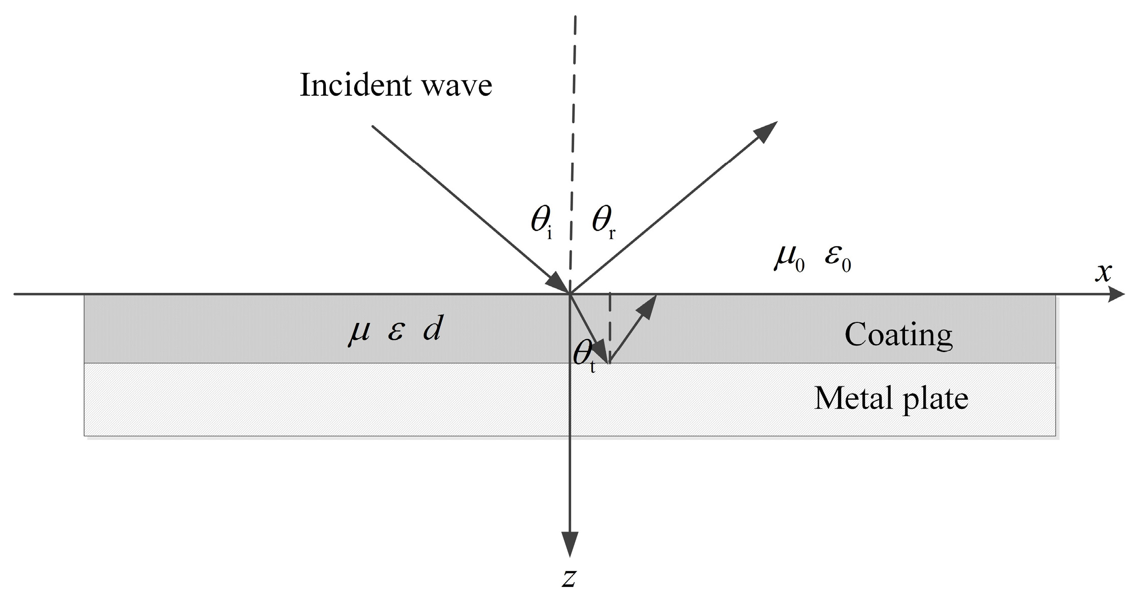
2.1. Performance Representation of Microwave Absorbing Materials

The far field of a microwave emitted by a radar can be regarded as a plane wave. Therefore, the microwave used to measure the reflectivity should be or should approximate a plane wave. Assume a plane wave is incident at an angle on the absorbing-material coating, and the plane that is composed of the incident vector and the normal vector is called the incident plane. If the incident electric field is perpendicular to the incident plane, the incident wave is called a vertically polarized wave. Otherwise, the incident wave is called a parallel polarized wave when the incident electric field vector is parallel to the incident plane. For a microwave incident on the absorbing-material coating at an angle, it can be decomposed into vertical and parallel polarization components [11]. Taking the vertically polarized wave as example, the propagation of the incident wave in the coating is shown in Figure 1.
µ0 and ε0 are the permeability and permittivity of air, respectively; µ, ε, and d are the permeability, permittivity, and thickness of the coating, respectively.
The unit vectors of the incident, reflected, and transmitted waves are represented as e i , e r , and e t , respectively. Then, we have
e i = e x sin θ i + e z cos θ i e r = e x sin θ r e z cos θ r e t = e x sin θ t + e z cos θ t
where θi, θr, and θt are angles of incidence, reflection, and transmission, respectively. The field expressions of incident, reflected, and transmitted waves are as follows [11]:
E i = E im e j k 0 ( x sin θ i + z cos θ i ) H i = 1 η 0 e i × E im e j k 0 ( x sin θ i + z cos θ i ) E r = E rm e j k 0 ( x sin θ r z cos θ r ) H r = 1 η 0 e r × E rm e j k 0 ( x sin θ r z cos θ r ) E t = E tm e j k ( x sin θ t + z cos θ t ) H t = 1 η 1 e t × E tm e j k ( x sin θ t + z cos θ t )
where E i and H i are incident electric field and magnetic field, respectively; E r and H r are reflected electric field and magnetic field, respectively; E t and H t are transmitted electric field and magnetic field, respectively; E im , E rm , and E tm are incident, reflected, and transmitted electric-field amplitudes, respectively; η0 and η1 are impedances of the plane wave in the air and in the coating, respectively; k 0 = ω ε 0 μ 0 and k = ω ε μ are propagation constants of the plane wave in the air and in the coating, respectively, and ω is the angular frequency of the wave. According to Snell's reflection and refraction laws [11], there are the following relationships:
θ i = θ r , sin θ t sin θ i = k k 0 ,
The total field at any point in the air is the superposition of incident and reflected fields. For the vertically polarized wave, the electric field has only the y component. The magnetic field has x and z components. The fields in the air are as follows [11]:
E 0 y = E i y + E r y = E im ( e j k 0 z cos θ i + Γ e j k 0 z cos θ i ) e j k 0 x sin θ i , H 0 x = H i x + H r x = E im η 0 cos θ i ( e j k 0 z cos θ i + Γ e j k 0 z cos θ i ) e j k 0 x sin θ i , H 0 z = H i z + H r z = E im η 0 sin θ i ( e j k 0 z cos θ i + Γ e j k 0 z cos θ i ) e j k 0 x sin θ i ,
where Eoy, Hox, and Hoz are the total y, x, and z components of electric field and magnetic field in the air, respectively; Eiy and Ery are y components of incident and reflected electric fields in the air, respectively; Hiy, Hry, Hiz, and Hrz are y and z components of incident and reflected magnetic fields in the air, respectively; Γ = E rm / E im is the reflection coefficient. According to the propagation theory of plane electromagnetic waves [11], the reflection coefficient of a plane wave incident on a metal surface is
Γ = 1
Therefore, the total field in the coating is expressed by
E 1 y = E t y + E tr y = j 2 τ E im sin [ k ( z d ) cos θ t ] e j k x sin θ t , H 1 x = H t x + H tr x = 1 η 1 j 2 τ E im cos θ t sin [ k ( z d ) cos θ t ] e j k x sin θ t , H 1 z = H t z + H tr z = 1 η 1 j 2 τ E im sin θ t sin [ k ( z d ) cos θ t ] e j k x sin θ t ,
where Ely, Hlx, and Hlz are the total y, x, and z components of electric field and magnetic field in the coating, respectively; Ety, Htx, and Htz are the transmitted y, x, and z components of electric field and magnetic field in the coating, respectively; Etry, Htrx, and Htrz are reflected y, x, and z components of transmitted electric field and magnetic field from the metal surface in the coating, respectively, and τ is the transmission coefficient. Based on the boundary conditions [11], the tangential components of electric field and magnetic field at z = 0 are continuous; i.e., Eoy = E1y, Hox = Hlx, then Γ is derived. In practice, the reflectivity is generally expressed by decibels of reflection coefficient as follows [12]:
R ( dB ) = 20 log | Γ |
where R(dB) is the reflectivity. The negative sign on the right side of the equation is to make the reflectivity positively related to the reflection coefficient.
Through the above analysis, we know the reflectivity is related to the permittivity and permeability of the absorbing material, the coating thickness, and the incident angle of the plane wave. The reflectivity will change when the incident angle varies. Traditionally, the reflectivity is regarded as the performance indicator of the absorbing material when the microwave is normally incident on the coating. In addition to measuring the permittivity and permeability to obtain the reflectivity, we can also get the reflectivity by measuring the reflected power of the plane wave. Assuming Pi and Pr are incident and reflected powers of a plane wave, respectively, the reflectivity can be expressed as [13]:
R ( dB ) = 10 log ( P r / P i )
The key factor to measure the reflectivity of the absorbing material on site is to produce an approximated plane wave as the far field of the microwave emitted by a Radar. We find that the field distribution at the aperture of the H-plane sectoral horn antenna can be approximated to a plane wave when the size of the horn is specially designed.

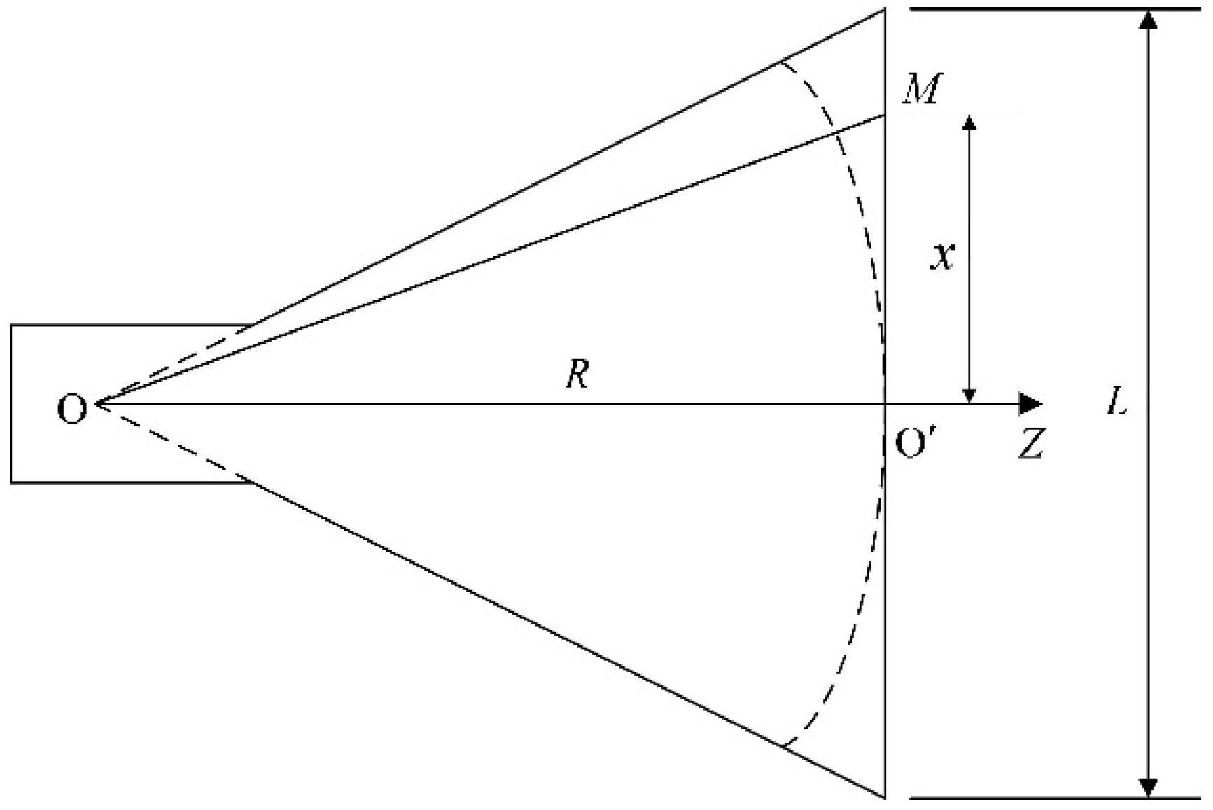
2.2. Field Analysis of H-plane Sectoral Horn Antenna

The excited field in the waveguide feeder of the H-plane horn antenna is the dominant TE10 mode which determines the field distribution in the horn [14]. The electric field has only the y component, which satisfies the following Helmholtz equation in cylindrical coordinates [14]:
2 E y r 2 + 1 r E y r + 1 r 2 2 E y θ 2 + ω 2 μ 0 ε 0 E y = 0
where Ey is the y component of the electric field; r and θ are coordinate variables. Solving Equation (9), we can get the field distribution in the horn. The field exhibits the characteristics of a traveling wave as r increases [14]. In addition to the dominant TE10 mode, higher order modes also exist locally in the horn because of the discontinuity at the throat and mouth of the horn [15]. At the throat, the energy of higher-order modes is tiny and can be ignored when the flare angle is small. At the mouth, the influence of higher-order modes on the field distribution is obvious. There are no analytic solutions to the problem, but it decreases as the mouth plane is enlarged [15].
The wave-front in the horn is cylindrical or spherical, illustrated by the curved-dash line in Figure 2. Therefore, the phase of the field is different along the aperture.
Taking the phase of point O’ as reference, the phase difference between point M and point O’ is given by
θ x = 2 π λ p ( R 2 + x 2 R ) = 2 π λ p [ x 2 2 R x 4 ( 2 R ) 3 + Δ ]
where θx is the phase difference; λp is the wavelength in the horn; R and x are illustrated in Figure 2; Δ is an infinitesimal. When the length of the horn is much larger than the width of the aperture, Equation (10) is simplified as follows:
θ x = π λ p x 2 R
Supposing the width of the aperture is L, the maximum phase difference is given by
θ x = π 4 λ p L 2 R
From Equation (12), we can see that the phase difference is inversely proportional to R. It tends to zero when R is large enough, then the field at the aperture can be approximated as a plane wave.

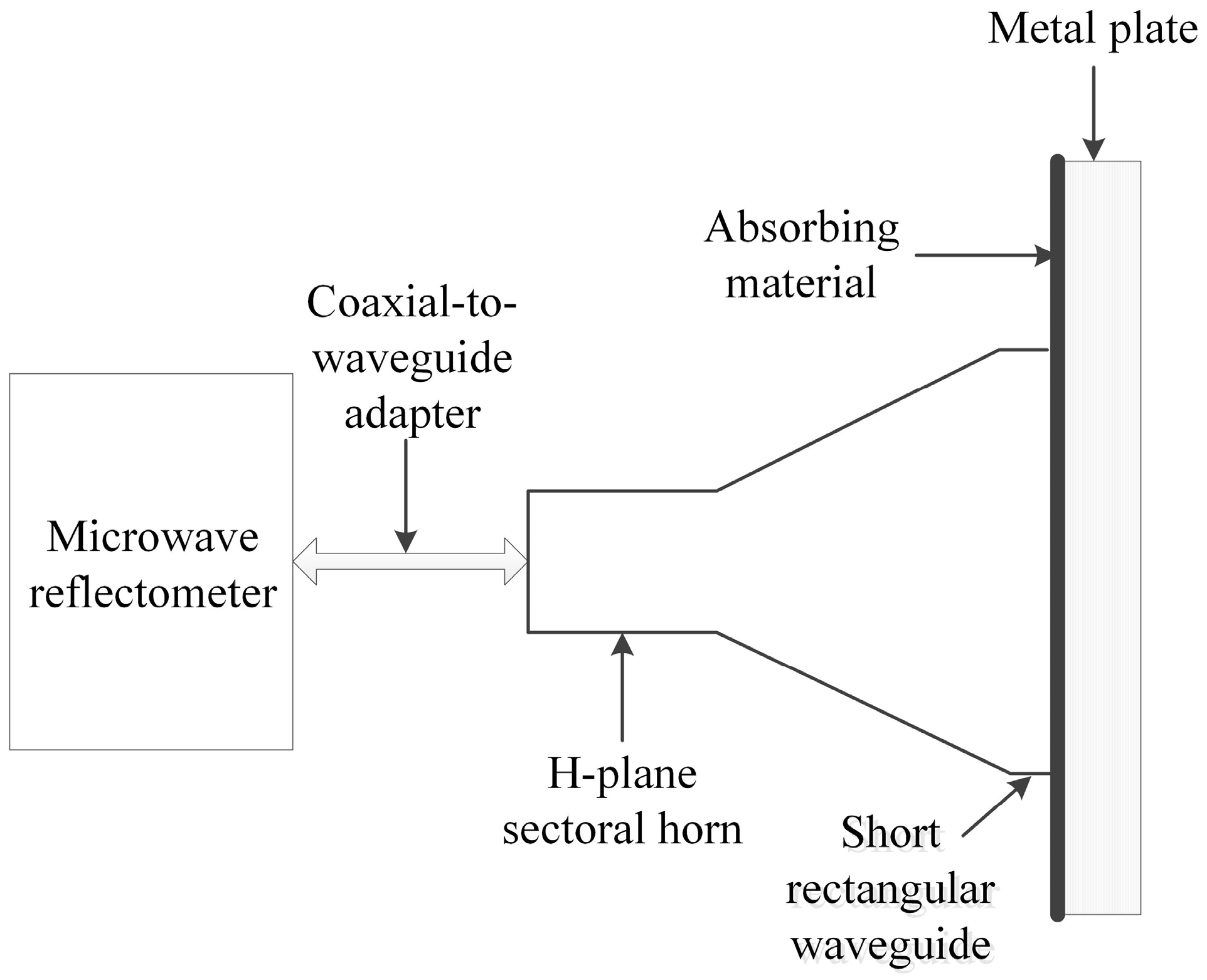
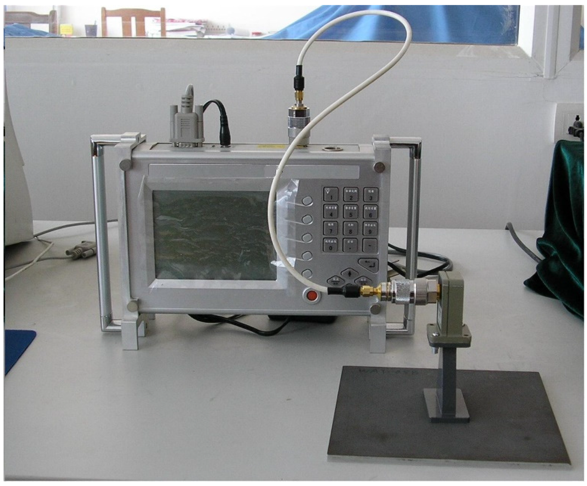
3. Experimental Scheme

The working frequency of an H-plane sectoral horn antenna is determined by the size of the waveguide feeder which is generally standardized. The flare angle and length of the horn are needed to be specially designed. The work was conducted by the aid of Ansoft’s simulation software high-frequency structure simulator. An H-plane sectoral horn antenna working at X band (8.2–12.4 GHz) was designed. In order to regulate the phase difference at the aperture, an additional short rectangular waveguide with the same size as the horn mouth is added at the aperture [16]. What is more, two flanges are added to both ends of the horn antenna. The flange at the waveguide feeder is used to conveniently connect the H-plane sectoral horn antenna with the microwave reflectometer. The other flange at the mouth is used to reduce the induced current on the outer surface and at the same time increase the contact area with the absorbing-material coating during on-site measurement [17].
The H-plane sectoral horn antenna is connected with a small microwave reflectometer via a coaxial-to-waveguide adapter to form the whole testing system as illustrated in Figure 3.
The small microwave reflectometer weighs less than 2.5 kg with dimensions of 260 mm × 180 mm × 70 mm (length × width × height). Its working frequency is between 3.3 GHz and 18 GHz. The testing reflectivity range is between 0.00 and 54.00 dB. In addition, the port of the microwave reflectometer is N type, then a coaxial-to-waveguide adapter is needed to connect the H-plane sectoral horn antenna. At the same time, it should be noted that the introduction of the adapter will cause a reflection of the microwave, and then affect the measurement results. The smaller the input-voltage–standing-wave ratio of the adapter is, the smaller the affection is [12]. What is more, in order to improve the operational flexibility, a coaxial cable can be used between the microwave reflectometer and the H-plane sectoral horn antenna.

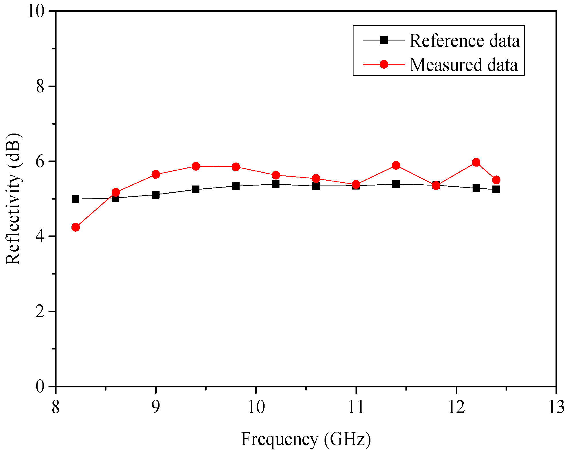
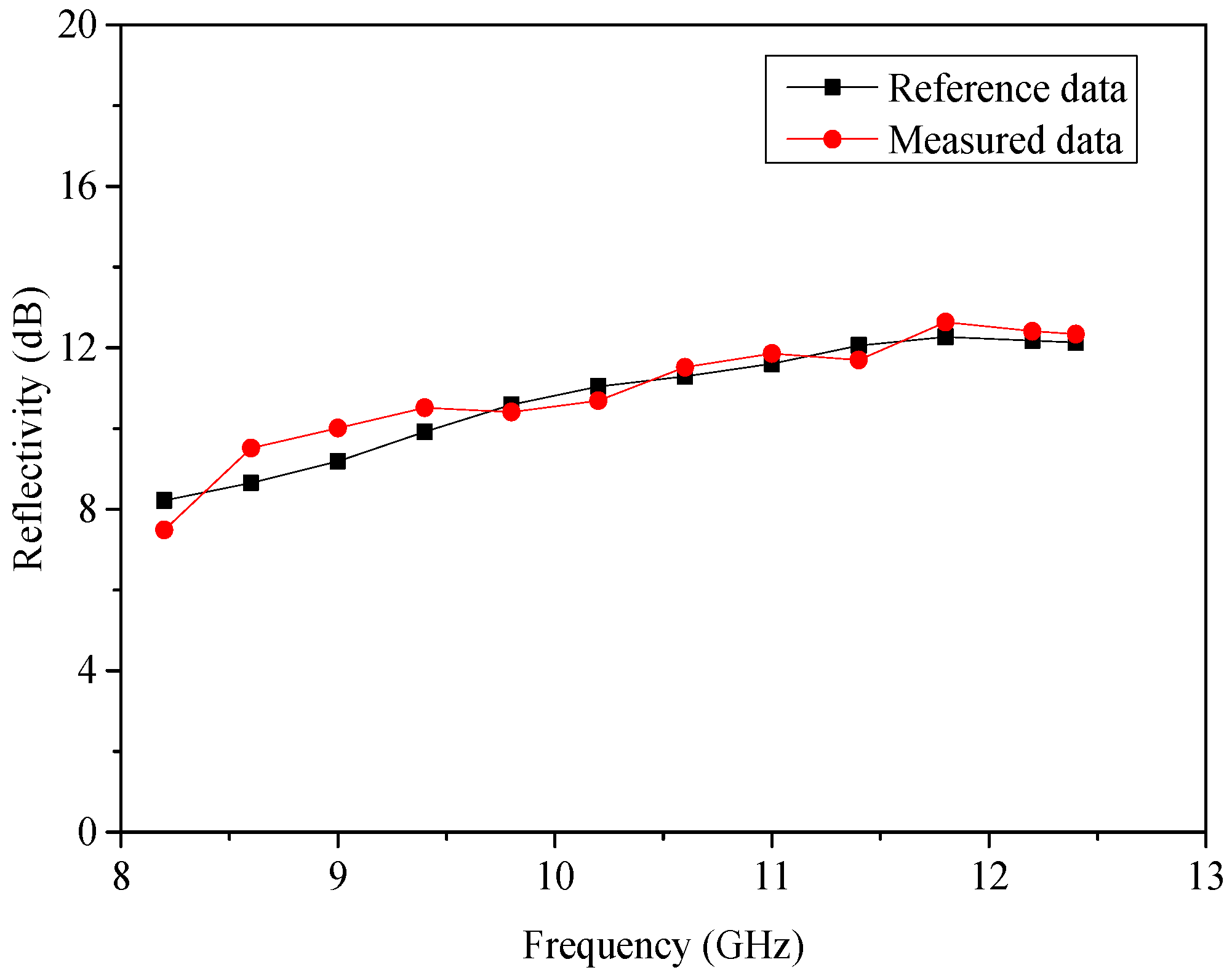
4. Results and Discussion

We conducted experiments on a kind of ferrite-based microwave-absorbing material to evaluate the testing scheme. The material was a composite, belonging to the coated absorber. It was painted on two metal plates with different thickness numbered as #1 and #2, respectively. The polyurethane in the material acted as the binder to make the material adhere firmly to the surface of the metal. The metal plate had a thickness of 0.5 cm with an area of 25 cm × 25 cm. The surface density of the coating was about 5 kg/m2. After painting, the coatings were polished to keep the surface flat and clean. The whole painting process were controlled by the material manufacturer. The #1 absorbing material coating had a thickness of 0.5 mm, and the #2 absorbing material coating had a thickness of 1 mm. The H-plane sectoral horn antenna was tightly attached to the two absorbing-material coatings during the test, illustrated in Figure 4.
Generally speaking, the microwave reflectometer needs to be calibrated before the measurement. However, the designed H-plane sectoral horn antenna has a nonstandard aperture. Routine calibrations cannot be carried out with standard calibrating devices. We adopted the following calibration method to eliminate systematic errors: Measure the reflectivity of a smooth metal plate in the X-band and take it as reference data, then test the two absorbing materials. The measured results are subtracted by the reference data. The resulted values are taken as the final reflectivity. The experimental results of the two absorbing materials are shown in Figure 5 and Figure 6, respectively.
The reference data were provided by the absorbing material manufacturer and obtained by the arc-frame method in the microwave anechoic chamber. From Figure 5 and Figure 6, we can see that the experimental results are in good agreement with the reference data as a whole. The thicker the coating is, the closer the measured reflectivity is to the reference data. The maximum deviation between experimental results and the reference data appears in absorbing material coating #1. The difference is 0.87 dB at 8.6 GHz (10 percent of the reference data).
Through the testing process, we know that errors emerge in the following aspects: (1) the field distribution at the aperture of the H-plane sectoral horn antenna is just an approximated plane wave, which inevitably affects the measurement results; (2) the coaxial-to-waveguide adapter used in the testing system is not an ideal one, and it introduces a reflection of microwave because of the nonzero input-voltage–standing-wave ratio, which has an impact on the measurement results; (3) the calibration method is also a source of errors because the calibration results are affected by the characteristics of the metal plate; (4) the H-plane sectoral horn antenna cannot wholly contact with the coating during the measurement, the air gaps can also affect the measurement because of the electromagnetic leakage [18,19]. Regardless, errors are inevitable, but tolerable for field measurement.
The experimental results validated the scheme at X band. Based on the same idea, we can evaluate the performance of absorbing materials in other frequency bands only if the size of the waveguide feeder is correctly selected, and the flare angle and length of the horn are specially designed.

5. Conclusions

We proposed a scheme to achieve field performance evaluation of microwave-absorbing materials, which adopted a small H-plane sectoral horn antenna as the testing probe and a small microwave reflectometer as the indicator. When the size of the H-plane sectoral horn antenna is specially designed, the field distribution at the aperture can be approximated to a plane wave as the far field of the microwave emitted by a radar unit. Therefore, the reflectivity can be measured on-site. The microwave reflectometer weighs less than 2.5 kg with dimensions of 260 mm × 180 mm × 70 mm, thus it is portable and suitable for field measurement. We conducted experiments on one kind of microwave-absorbing material to validate the scheme. Experimental results illustrated an agreement with the reference data as a whole. The maximum deviation was less than 10 percent of the reference data. By designing different H-plane sectoral horn antennas, the reflectivity at a wider range of frequency can be obtained.

Acknowledgments

This work was supported by Shandong Provincial Natural Science Foundation under Grant No. ZR2014DL008, and the science and technology research project of Yantai under Grant No. 2016YT06000198.

Author Contributions

Shaopeng Guan and Daiping Jia conceived and designed the experiments; Shaopeng Guan performed the experiments; Yongyu Wang analyzed the data; Shaopeng Guan wrote the paper; Yongyu Wang proofreading the grammar.

Conflicts of Interest

The authors declare no conflict of interest.

References

  1. Petrov, V.; Gagulin, V. Microwave absorbing materials. Inorg. Mater. 2001, 2, 93–98. [Google Scholar] [CrossRef]
  2. Wang, C.; Han, X.; Xu, P.; Zhang, X.; Du, Y.; Hu, S.; Wang, J.; Wang, X. The electromagnetic property of chemically reduced graphene oxide and its application as microwave absorbing material. Appl. Phys. Lett. 2011, 7, 072906. [Google Scholar] [CrossRef]
  3. Kats, M.A.; Sharma, D.; Lin, J.; Genevet, P.; Blanchard, R.; Yang, Z.; Qazilbash, M.M.; Basov, D.; Ramanathan, S.; Capasso, F. Ultra-thin perfect absorber employing a tunable phase change material. Appl. Phys. Lett. 2012, 22, 221101. [Google Scholar] [CrossRef]
  4. Kong, L.; Li, Z.; Liu, L.; Huang, R.; Abshinova, M.; Yang, Z.; Tang, C.; Tan, P.; Deng, C.; Matitsine, S. Recent progress in some composite materials and structures for specific electromagnetic applications. Int. Mater. Rev. 2013, 4, 203–259. [Google Scholar] [CrossRef]
  5. Padhy, S.; Sanyal, S.; Meena, R.; Chatterjee, R.; Bose, A. Characterization and performance evaluation of radar absorbing materials. J. Electromagnet. Wave 2013, 2, 191–204. [Google Scholar] [CrossRef]
  6. Knott, E.F.; Shaeffer, J.F.; Tuley, M.T. Radar Cross Sections, 2nd ed.; SciTech Publishing: Greensboro, NC, USA, 2004; pp. 361–406. [Google Scholar]
  7. Zoughi, R. Microwave Non-Destructive Testing and Evaluation; Springer: Berlin/Heidelberg, Germany, 2000; pp. 209–245. [Google Scholar]
  8. Addamo, G.; Virone, G.; Vaccaneo, D.; Tascone, R.; Peverini, O.A.; Orta, R. An adaptive cavity setup for accurate measurements of complex dielectric permittivity. Prog. Electromagn. Res. 2010, 105, 141–155. [Google Scholar] [CrossRef]
  9. Hasar, U.C. Unique permittivity determination of low-loss dielectric materials from transmission measurements at microwave frequencies. Prog. Electromagn. Res. 2010, 107, 31–46. [Google Scholar] [CrossRef]
  10. Zhou, Y.; Li, E.; Guo, G.; Gao, Y.; Yang, T. Broadband complex permittivity measurement of low loss materials over large temperature ranges by stripline resonator cavity using segmentation calculation method. Prog. Electromagn. Res. 2011, 113, 143–160. [Google Scholar] [CrossRef]
  11. Faria, J.B. Electromagnetic Foundations of Electrical Engineering; John Wiley & Sons: Hoboken, NJ, USA, 2008; pp. 243–273. [Google Scholar]
  12. Pozar, D.M. Microwave Engineering, 4th ed.; John Wiley & Sons: Hoboken, NJ, USA, 2009; pp. 28–39. [Google Scholar]
  13. Collin, R.E. Foundations for Microwave Engineering; Wiley & Sons: Hoboken, NJ, USA, 2007; pp. 17–70. [Google Scholar]
  14. Balanis, C.A. Antenna Theory: Analysis and Design; John Wiley & Sons: Hoboken, NJ, USA, 2012; pp. 739–810. [Google Scholar]
  15. Silver, S. Microwave Antenna Theory and Design; McGraw-Hill Book Company, Inc.: New York, NY, USA, 1949; pp. 334–387. [Google Scholar]
  16. Sauleau, R.; Coquet, P.; Thouroude, D.; Daniel, J.-P.; Matsui, T. Radiation characteristics and performance of millimeter-wave horn-fed Gaussian beam antennas. IEEE Trans. Antenna Propag. 2003, 3, 378–387. [Google Scholar] [CrossRef]
  17. Chung, B.K. Dielectric constant measurement for thin material at microwave frequencies. Prog. Electromagn. Res. 2007, 75, 239–252. [Google Scholar] [CrossRef]
  18. Micheli, D.; Apollo, C.; Pastore, R.; Marchetti, M. X-band microwave characterization of carbon-based nanocomposite material, absorption capability comparison and RAS design simulation. Compos. Sci. Technol. 2010, 70, 400–409. [Google Scholar] [CrossRef]
  19. Micheli, D.; Apollo, C.; Pastore, R.; Morles, R.B.; Coluzzi, P.; Marchetti, M. Temperature, atomic oxygen and outgassing effects on dielectric parameters and electrical properties of nanostructured composite carbon-based materials. Acta Astronaut. 2012, 76, 127–135. [Google Scholar] [CrossRef]
Figure 1. Propagation of vertically polarized wave in the absorbing-material coating.
Coatings 07 00038 g001
Figure 2. Cross section of the H-plane sectoral horn antenna.
Coatings 07 00038 g002
Figure 3. Schematic diagram of the testing system.
Coatings 07 00038 g003
Figure 4. Testing process.
Coatings 07 00038 g004
Figure 5. Experimental results of absorbing material coating #1.
Coatings 07 00038 g005
Figure 6. Experimental results of absorbing material coating #2.
Coatings 07 00038 g006

