Article

Development of a Fabrication Process Using Suspension Plasma Spray for Titanium Oxide Photovoltaic Device

Ashikaga Institute of Technology, 268-1 Omae, Ashikaga, Tochigi, 326-8558, Japan
*
Author to whom correspondence should be addressed.
Coatings 2017, 7(3), 40; https://doi.org/10.3390/coatings7030040
Submission received: 20 September 2016 / Revised: 24 February 2017 / Accepted: 1 March 2017 / Published: 4 March 2017

Abstract

:
In order to reduce the high costs of conventional materials, and to reduce the power necessary for the deposition of titanium dioxide, titanium tetrabutoxide has been developed in the form of a suspension of TiO2 using water instead of expensive ethanol. To avoid sedimentation of hydroxide particles in the suspension, mechanical milling of the suspension was conducted in order to create diffusion in colloidal suspension before using it as feedstock. Consequently, through the creation of a colloidal suspension, coating deposition was able to be conducted without sedimentation of the hydroxide particles in the suspension during the deposition process. Though an amorphous as-deposited coating was able to be deposited, through post heat treatment at 630 °C for 60 min, the chemical structure became anatase rich. In addition, it was confirmed that the post heat treated anatase rich coating had enough photo-catalytic activity to decolor methylene-blue droplets. From these results, this technique was found to have high potential in the low cost photo-catalytic titanium coating production process.

1. Introduction

Thin titanium oxide films for photo-catalytic application (anatase TiO2, etc.) can be deposited by various deposition techniques such as sputtering [1], metalorganic chemical vapour deposition (MOCVD) [2], spray pyrolysis [3], the sol-gel process [4], thermal spray [5,6,7,8], or by various other methods. However, there are several engineering problems associated with these deposition processes, such as the necessity of vacuum equipment, low deposition rates, deposition time, the requirement of special and costly equipment, as well as feedstock powder [9]. Recently, some atmospheric thermal plasma processes for titania deposition have been successfully developed [10]. It is still difficult to develop the atmospheric thermal plasma process, especially in cases where low power DC arc discharge equipment is being used. In our previous study, in order to reduce equipment costs, a thermal spray process for photo-catalytic titanium oxide coating was fabricated using 1 kW class Atmospheric Solution Precursor Plasma Spray (ASPPS) equipment. Titanium oxide film deposition was then carried out [9,11]. Although photo-catalytic anatase rich titanium oxide films were successfully deposited, the feedstock cost could not be decreased because of the necessity of expensive anhydrous ethanol which is required to create the low viscosity titanium iso butoxide solution (TTIB, Ti(OC4H9)4) without hydration of TTIB due to residual water in the ethanol. Although the anhydrous ethanol-titanium-oxide-suspension method is a possible solution to the above problems, it is difficult to use this method in practice. This method creates large secondary particles as a result of hydrolysis due to the presence of TTIB as well as the fact that titanium dioxide is insoluble in water. It has large particles, which solidify when in contact with water (hydrolysis). These properties prevent the suspension from being stable and mixing with nanoparticles in water. It is also difficult to inject or spray such a mixture. Titanium tetra-butoxide was developed in the form of a titanium hydroxide suspension by using nothing but stable water to prepare the titanium hydroxide suspension and then by milling and filtering the suspension. The suspension plasma spray (SPS) that developed new feedstock material seems to be highly promising as a low cost starting material and in the rapid formation of functional thin films.

2. Experimental Procedure
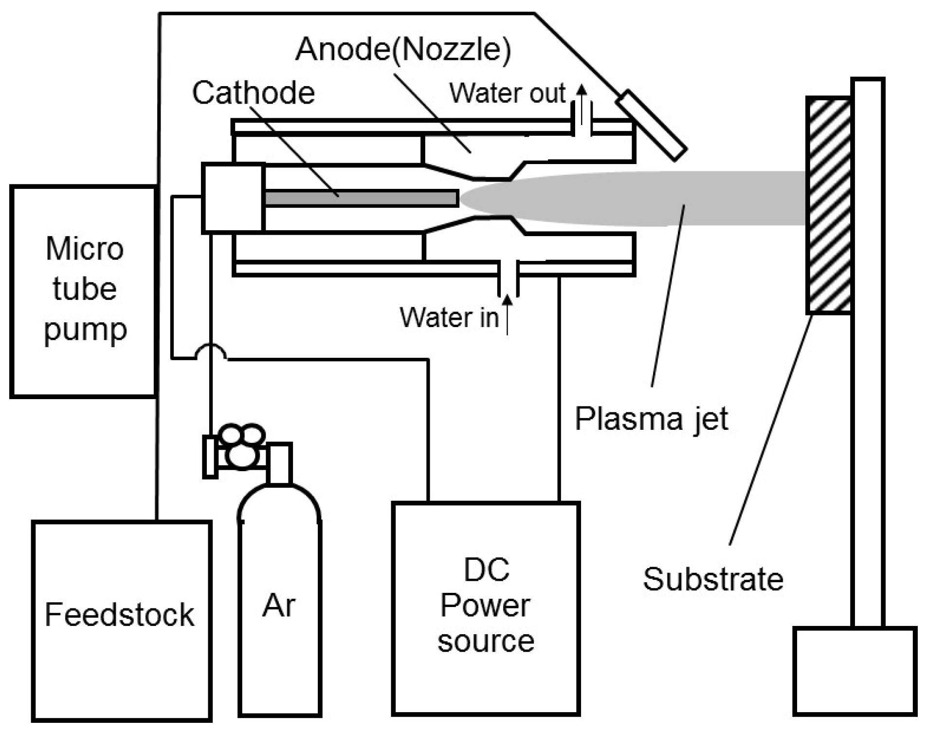
2.1. Method

The tools used for mixing titanium oxide with water are shown in Figure 1. They consist of a micro filter, a mixer, and a special container (mortar and pestle) for mixing as well as for crushing and grinding. An amount of 2 mL of TTIB is diluted with stable water, and 20 mL of water is gradually added to the TTIB. It is then mixed from one to 4 min before performing suspension filtration, in which we force large particles to pass through the holes of the filter and take the shape and size of the filter holes in the form of submicron particles. In order to reduce the particles to a smaller size than the holes of the filter, we use milled particles. We continue mixing the suspension after this grinding/milling process, until the suspension is ready to use and is then injected into the plasma jet. Titanium oxide deposited by the suspension plasma spray is shown in Figure 2. Heat treatment is then performed on all samples using an electric furnace. The heat treatment is performed by gradually increasing the heat of the samples from 30 to 630 °C for approximately 60 min.
The equipment used consists of a plasma torch, a DC power feeding system, an air pressure spray (starter material feed), and a working Ar gas feeding system. The plasma torch is cooled by a water flow around the nozzle. The anode, which has a suspension feeding port at its head, has a constrictor that is 6 mm in diameter. The nozzle shown in Figure 3 and Figure 4 explain how this equipment was made for the experiment in this study. In order to promote the vaporization of the starting material and to raise the temperature of titanium particles, Ar was used as the working gas. Mass flow rate of the gas was fixed at 5–10 SLM, and the discharge current was fixed at 50–60 A. The titanium hydroxide (Ti(OH)4) suspension submicron particles were suspended in water.

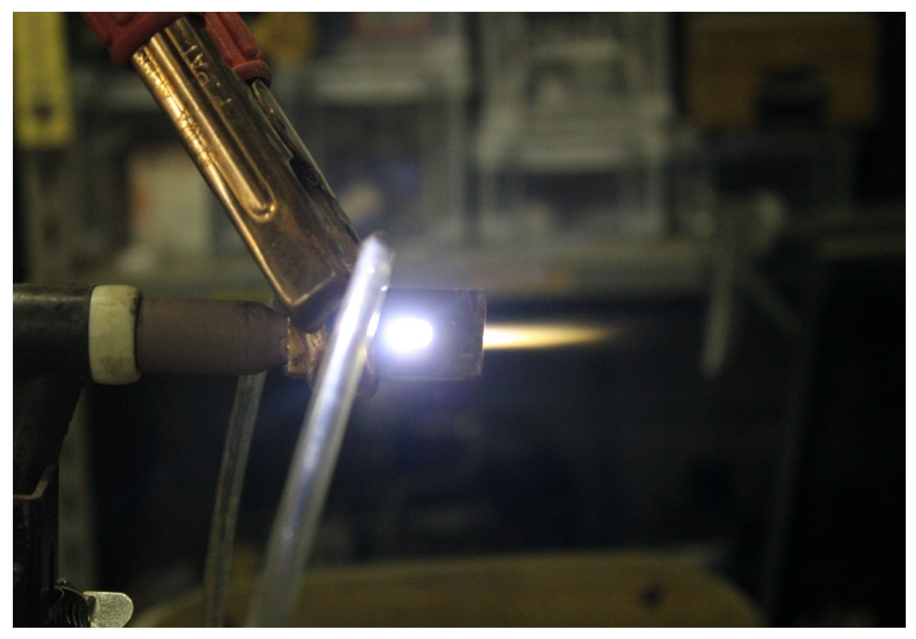
2.2. Plasma Spray Parameters

Titanium oxide deposited by suspension plasma spraying is shown in Table 1. The anode, which has a suspension feeding port at its head, has a constrictor that is 6 mm in diameter. The nozzle shown in Figure 4 demonstrates how this equipment was configured for the experiment in this study. The anode is 450 mm in length and 20 mm in width.

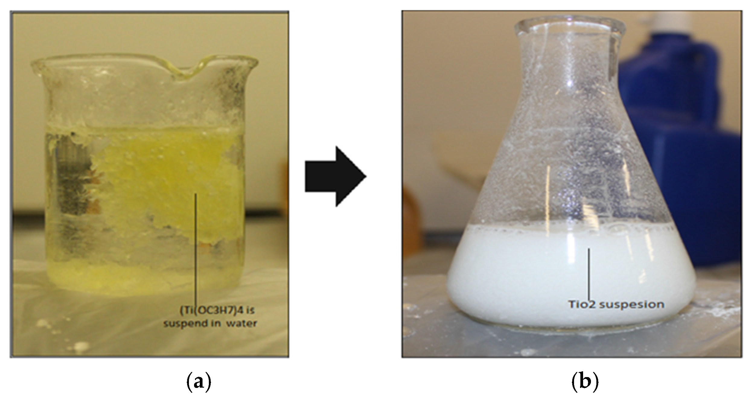
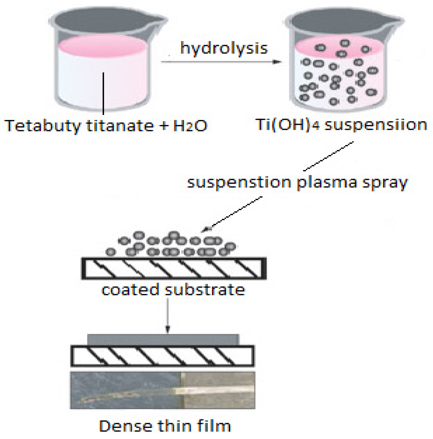
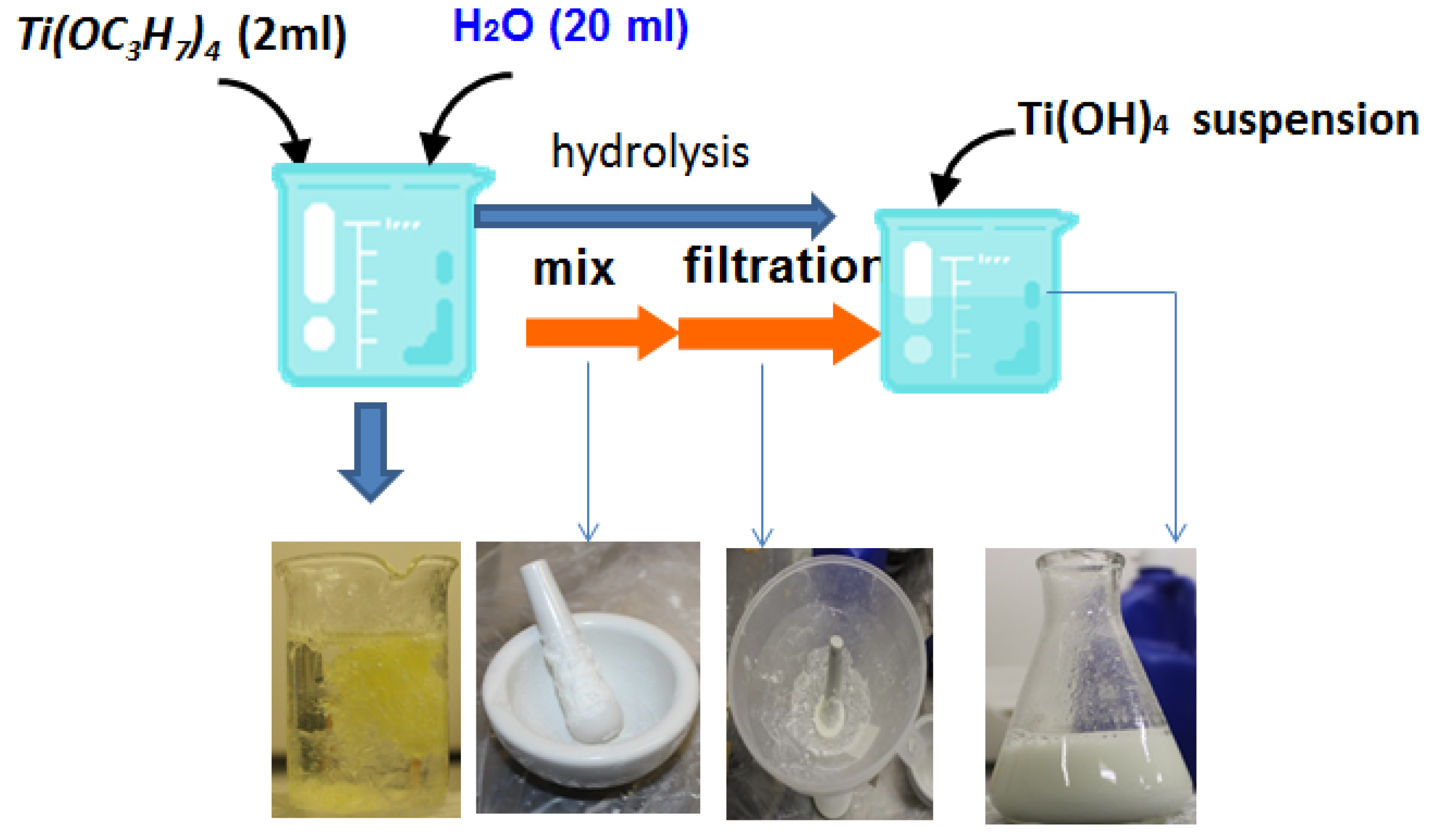
2.3. Suspension Preparation

Ethanol has solvent properties and is a versatile solvent, miscible with water and titanium tetra butoxide among many other materials. However, it is expensive. One way to solve the problem of cost is to use a starting material that does not require ethanol and which uses only distilled water. In this process, the reaction between the alkoxide precursor and the desired amount of water occurred in an anhydrous alcohol medium. The hydrolysis and condensation reactions can be summarized as follows:
*Hydrolysis: Ti(OC4H9)4 + 4H2O → Ti(OH)4 + 4C4H9OH
*Polymerization and crystallization (in the plasma jet and on the substrate):
Ti(OH)4 → TiO2 + 2H2O
It is difficult to inject or spray the suspension before the filtration process because of the size of the particles. Therefore, it is necessary to use equipment to facilitate mixing titanium oxide with water. The equipment consists of a filter funnel, a mixer, and a special container (mortar and pestle), which is used for crushing, grinding, and mixing, as shown in Figure 5. Then begins the process of mixing for one to four minutes before the commencement of suspension filtration in which we force large particles to pass through the holes of the filter and take the shape and size of the holes to form of submicron particles. In order to obtain a smaller particle size than the holes of the filter, we use the milled particles, and mix the suspension after this process until the suspension is ready for use. At this point, it is injected into the plasma jet.

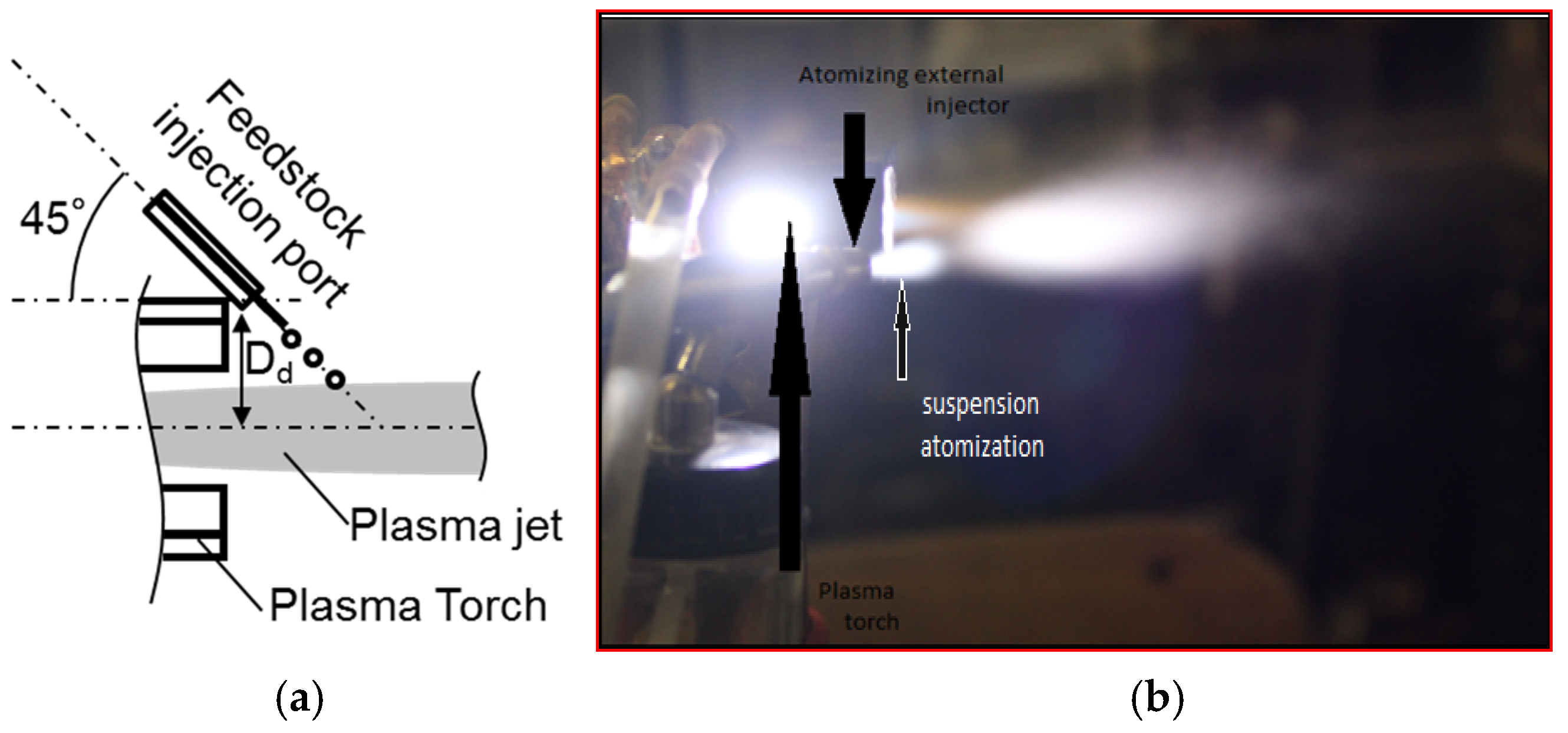
2.4. Injection Method

A radial injection of the suspension feedstock was made by using two different modes: (i) an internal injection mode (Figure 6a) using an airbrush atomization feeding system, which was 0.4 mm in diameter in Table 1, and an internal port 6 mm in diameter; (ii) an external injection mode (Figure 6b) using the same system, where the suspension is first atomized and then injected into the plasma jet.

3. Results and Discussion

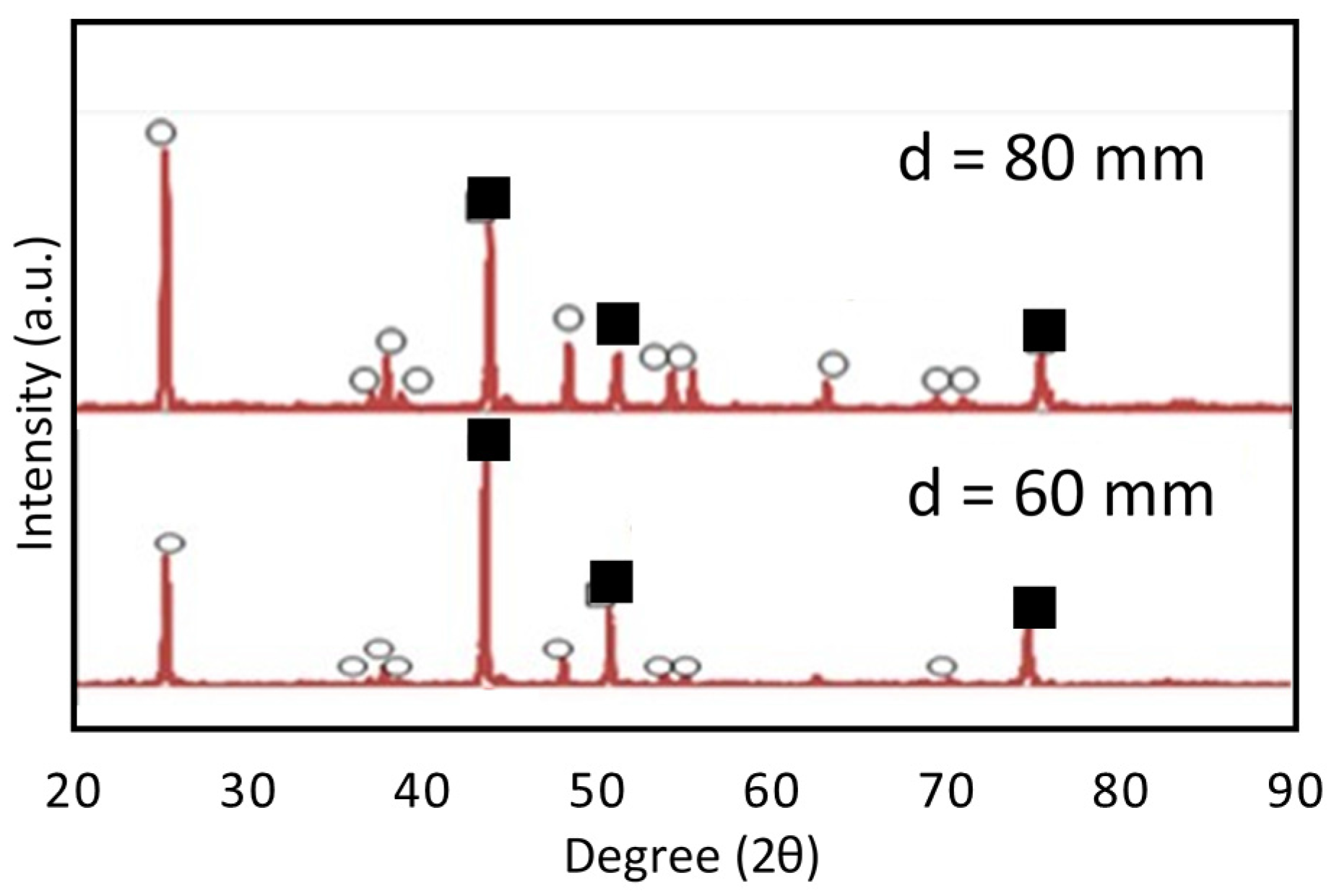
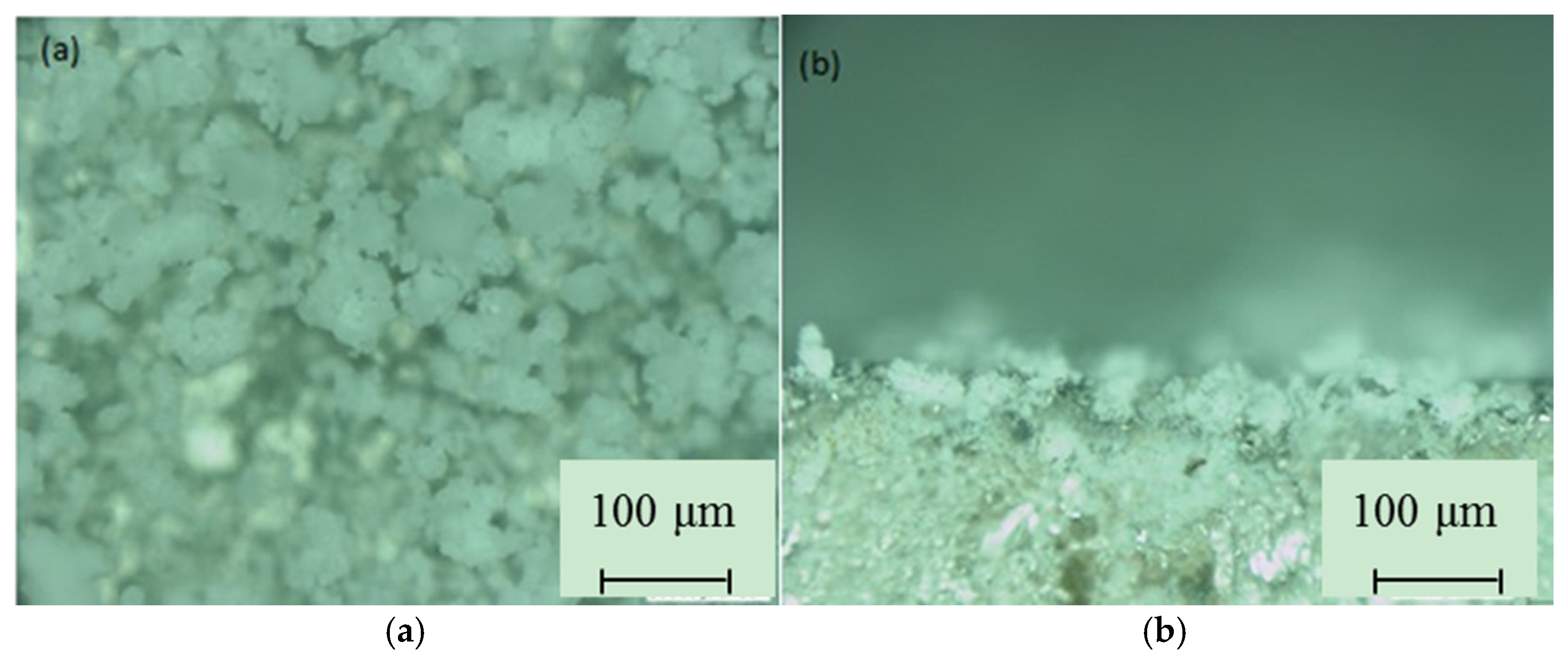
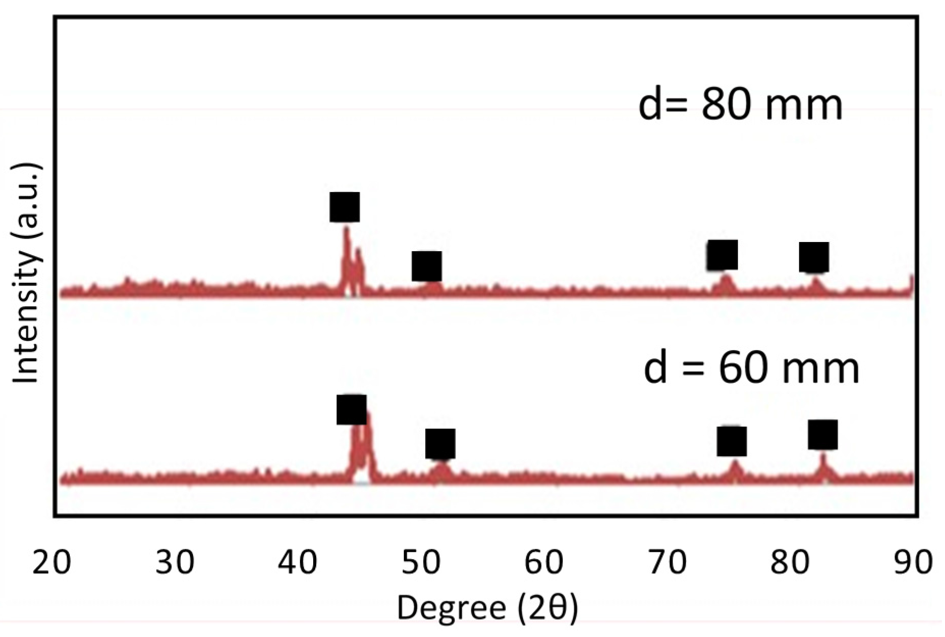
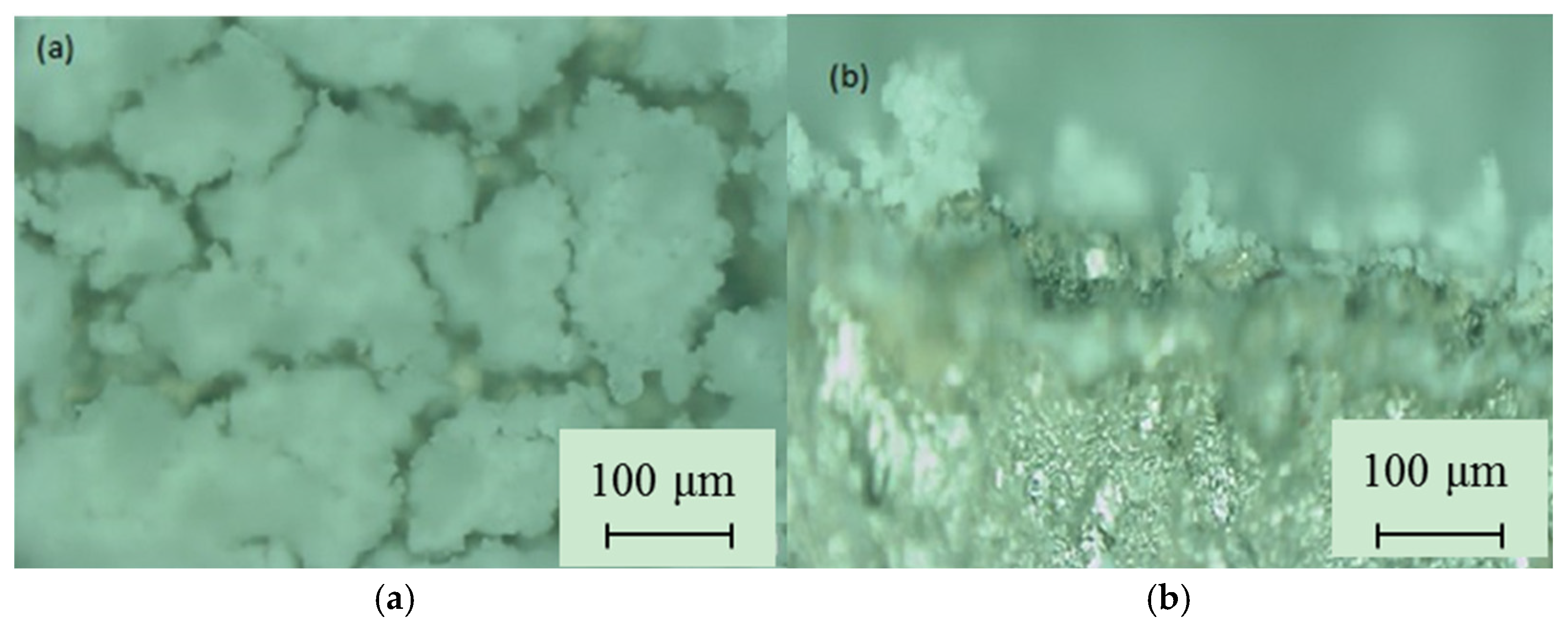
3.1. SPS Titanium Oxide Film

The coated samples before heat treatment seemed to be in an amorphous phase (Figure 7). When the deposition was performed with a low substrate temperature, the starting material did not have enough mobility to form a crystalline structure. Following that, heat treatment was conducted on all of the titanium oxide films that were deposited on the substrate. The films were heated gradually from 30 to 630 °C with a temperature increase of 10 °C·min−1 for approximately 60 min. In respect to the XRD patterns of the heat treated films, anatase crystalline peaks appeared for all samples and became sharper by increasing distances from d = 60 mm to 80 mm. Figure 8 shows the XRD pattern of the samples deposited at 80 mm, 60 mm deposition distance. At 80 mm in deposition distance, the starting material heating time was longer than that of the 60 mm sample. Therefore, the quantity of deposited particles at 80 mm was thought to be higher than the quantity of the 60 mm sample. From these results, it was proven that crystallization of the titania films occurred during heat treatment.
The top-surface and cross-section micrographs of suspension sprayed coating using differing distances are shown in Figure 9 and Figure 10. The microstructural investigations revealed that the suspension plasma coating presented a morphology, which was caused by the way that the suspension was injected into the plasma jet. The coating, in the case of 60 mm in spray distance (d = 60 mm), is homogeneous and has a grainy structure. The top-surface microscope analyses revealed the presence of agglomerates of grains that are porous, loosely bound, and have a thick film. On the other hand, in the case of d = 80 mm, the film had a grainy and porous structure. The difference in the coatings’ microstructure and surface shape can be related to the type of suspension and evolution of the suspension droplets in the plasma jet. According to the particle sizes shown, the film deposition rate dramatically increased with increasing deposition distance (Figure 8).

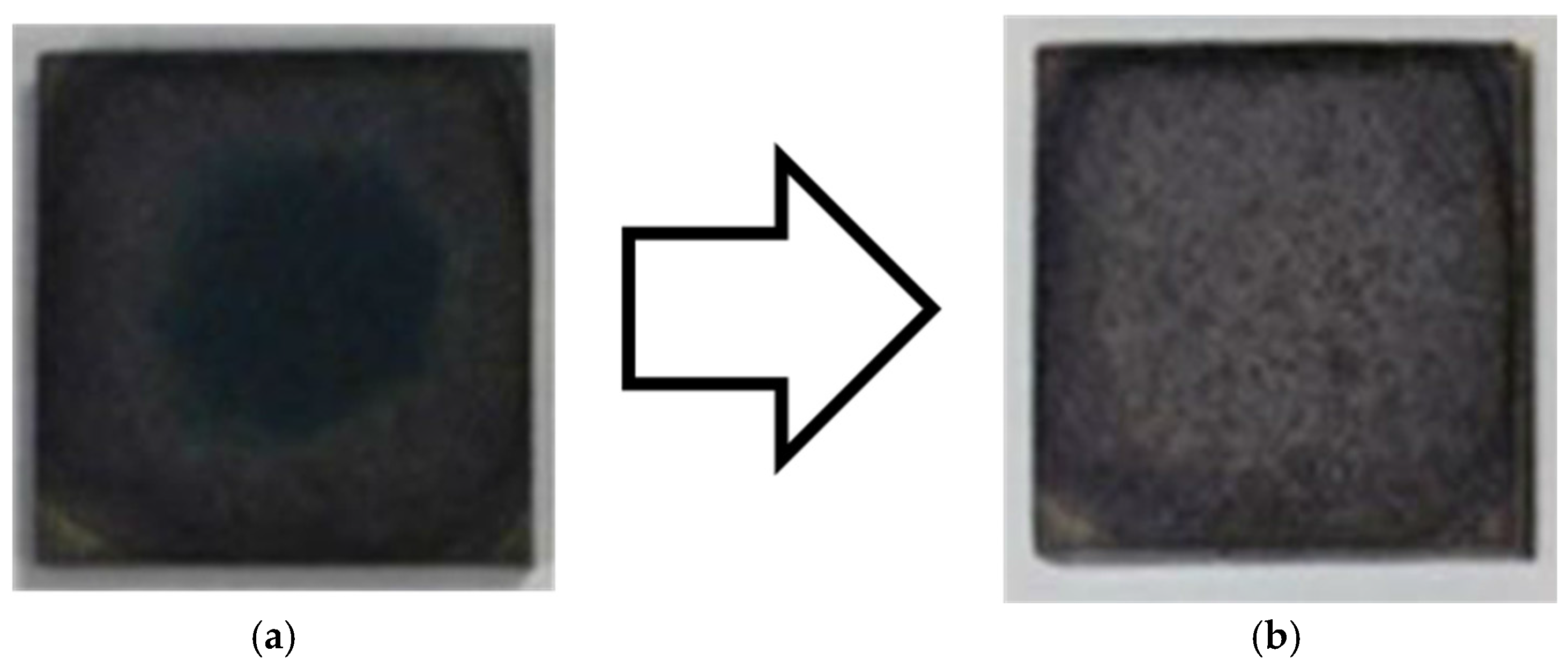
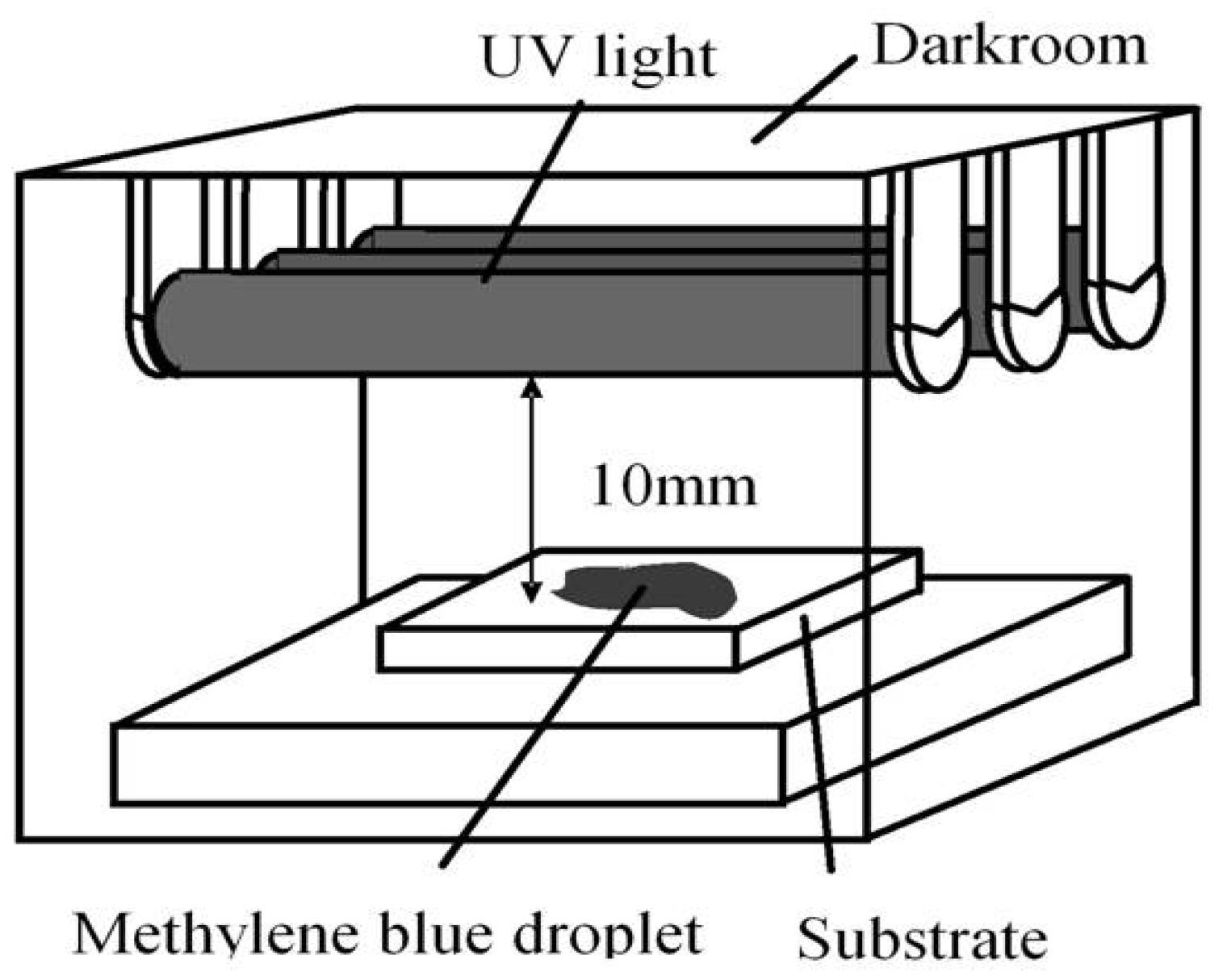
3.2. Photocatalytic Activity of TiO2 Coating

In order to confirm the photo-catalytic property of the coatings, photo-catalytic activity of the sprayed TiO2 suspension coating was evaluated by using UV irradiation equipment and measurements of the degradation of an aqueous solution of methylene-blue were conducted (decoloration test) (Figure 11) [9]. Figure 12 shows the results of the methylene-blue decoloration test in the case of the coating deposition at a distance of d = 80 mm. In both cases of the coatings at the distances of d = 60 mm and 80 mm, decoloration could be confirmed after 1 week of UV irradiation. From these results, it was confirmed that this technique has enough potential to deposit photo-catalytic titanium oxide films.

4. Conclusions

In order to develop low cost materials that can be used for the titanium dioxide film deposition process, deposition of high-rate film using low cost materials was carried out. Thick photo-catalyst film was obtained using an atmospheric suspension plasma spray with spray injectors as a fabrication process. Consequently, anatase film was obtained, and it was confirmed that the anatase films had photo-catalytic properties by using a methylene-blue droplet test and its decoloration test. From these results, this low cost starting material with atmospheric SPS has the potential for a high rate and low cost, functional, oxide film deposition.

Author Contributions

H. Sagr Hadi A created the SPS equipment for this study, conducted TiO2 film deposition, investigated macrostructures of deposited films by optical microscope and XRD. Y. Ando designed and created the advanced prototype of the SPS equipment using a commercial arc welding equipment.

Conflicts of Interest

The authors declare no conflict of interest.

References

  1. Sima, C.; Waldhauser, W.; Lacknar, J.; Kahn, J.; Kahn, M.; Nicolae, I.; Viespe, C.; Grigoriu, C.; Manea, A. Properties of TiO2 thin films deposited by RF magnetron sputtering. J. Optoelectron. Adv. Mater. 2007, 9, 1446–1449. [Google Scholar]
  2. Cimpean, A.; Popescu, S.; Ciofrangeanu, C.M.; Gleizes, A.N. Effects of LPMOCVD prepared TiO2 thin films on the in vitro behavior of gingival fibroblasts. Mater. Chem. Phys. 2011, 125, 485–492. [Google Scholar] [CrossRef] [Green Version]
  3. Oja, I.; Mere, A.; Krunks, M.; Solterbeck, C.-H.; Es-Souni, M. Properties of TiO2 Films Prepared by the Spray Pyrolysis Method. Solid State Phenom. 2004, 99, 259–264. [Google Scholar] [CrossRef]
  4. Kajitvichyanukula, P.; Ananpattarachaia, J.; Pongpomb, S. Sol–gel preparation and properties study of TiO2 thin film for photocatalytic reduction of chromium(VI) in photocatalysis process. Sci. Technol. Adv. Mater. 2005, 6, 352–358. [Google Scholar] [CrossRef]
  5. Zhao, X.; Liu, X.; Ding, C.; Chu, P.K. In vitro bioactivity of plasma-sprayed TiO2 coating after sodium hydroxide treatment. Surf. Coat. Technol. 2006, 200, 5487–5492. [Google Scholar] [CrossRef]
  6. Li, C.-J.; Yang, G.-J.; Wang, Y.-Y.; Li, C.-X.; Ye, F.-X.; Ohmori, A. Phase Formation during Deposition of TiO2 Coatings through High Velocity Oxy-Fuel Spraying. Mater. Trans. 2006, 47, 1690–1696. [Google Scholar] [CrossRef]
  7. Yang, G.-J.; Li, C.-J.; Han, F.; Li, W.-Y.; Ohmori, A. Low Temperature Deposition and Characterization of TiO2 Photocatalytic Film through Cold Spray. Appl. Surf. Sci. 2008, 254, 3979–3982. [Google Scholar] [CrossRef]
  8. Yamada, M.; Isago, H.; Nakano, H.; Fukumoto, M. Cold Spraying of TiO2 Photocatalyst Coating with Nitrogen Process Gas. J. Therm. Spray Technol. 2010, 19, 1218–1223. [Google Scholar] [CrossRef]
  9. Ando, Y.; Tobe, S.; Tahara, H. Photo-catalytic TiO2 film deposition by atmospheric TPCVD. Vacuum 2006, 80, 1278–1283. [Google Scholar] [CrossRef]
  10. Popescu, S.; Jerby, E.; Meir, Y.; Barkay, Z.; Ashkenazi, D.; Mitchell, J.B.A.; Le Garrec, J.L.; Narayanan, T. Plasma column and nano-powder generation from solid titanium by localized microwaves in air. J. Appl. Phys. 2015, 118, 023302. [Google Scholar] [CrossRef]
  11. Ando, Y. Titanium Oxide Film Deposition on Acrylic Resin by Atmospheric TPCVD. IEEE Trans. Plasma Sci. 2009, 37, 2202–2206. [Google Scholar] [CrossRef]
Figure 1. Creation of the titanium hydroxide suspension. (a) Before hydrolysis; (b) After hydrolysis.
Coatings 07 00040 g001
Figure 2. Illustration of the estimated film deposition mechanism in this suspension plasma spray (SPS) process.
Coatings 07 00040 g002
Figure 3. Schematic diagram of the SPS equipment.
Coatings 07 00040 g003
Figure 4. Plasma jet generated by our thermal spray equipment.
Coatings 07 00040 g004
Figure 5. The shape of submicron particles.
Coatings 07 00040 g005
Figure 6. Configuration of the suspension plasma spray torch. (a) Illustration of the feedstock injection port; (b) Appearance of the plasma jet.
Coatings 07 00040 g006
Figure 7. XRD patterns of SPS films before heat treatment. (d = deposition distance, ■: Fe (substrate)).
Coatings 07 00040 g007
Figure 8. XRD patterns of SPS films after heat treatment (d = deposition distance, ●: Anatase, ■: Fe (substrate)).
Coatings 07 00040 g008
Figure 9. Micrographs of suspension sprayed coating deposited at d = 60 mm. (a) Top-surface; (b) Cross-section.
Coatings 07 00040 g009
Figure 10. Micrographs of suspension sprayed coating deposited at d = 80 mm. (a) Top-surface; (b) Cross-section.
Coatings 07 00040 g010
Figure 11. Schematic diagram of the equipment used in methylene-blue decoloration test.
Coatings 07 00040 g011
Figure 12. Results of methylene blue decoloration test when the coating was deposited at d = 80 mm (d = deposition distance). (a) Before UV irradiation; (b) After 7-day UV irradiation.
Coatings 07 00040 g012
Table 1. Suspension plasma spray parameters used to deposit the TiO2 coatings in this study.
Process ParameterValue
Sandblasting realizedAlways
Working gas compositionAr
Working gas flow rate, L/min5–15
Spray distance, mm100–150
Discharge current, A60–50
Constrictor diameter of plasma torch nozzle, mm 6
FeedstockTi(OH)4 suspension *
Feedstock feed rate, mL/min11
Feedstock injection port, diameter, mm0.4
Deposition distance, mm60–80
* Created by hydrolysis of titanium tetraisobutoxide (TTIB, Ti(OC4H9)4) (volume ratio of TTIB/H2O = 2/20).

