
Studies on the Effect of Arc Current Mode and Substrate Rotation Configuration on the Structure and Corrosion Behavior of PVD TiN Coatings

1
School of Engineering, RMIT University, Melbourne 3001, Australia
2
School of Science, RMIT University, Melbourne 3001, Australia
3
Defence Materials Technology Centre, Melbourne 3122, Australia
4
Sutton Tools Pty Ltd., Melbourne 3074, Australia
*
Author to whom correspondence should be addressed.
Coatings 2017, 7(4), 50; https://doi.org/10.3390/coatings7040050
Submission received: 21 September 2016
/
Revised: 7 March 2017
/
Accepted: 30 March 2017
/
Published: 4 April 2017
(This article belongs to the Special Issue Five Years of Coatings: Coatings Science and Technology for the 21st Century)
Abstract
:Thin, hard cathodic arc evaporated (CAE) metal nitride coatings are known to contain defects such as macro-particles, pinholes, voids and increased porosity, leading to reduced corrosion resistance. The focus of this research investigation was to compare the structure and corrosion behaviour of cathodic arc evaporated (CAE) TiN coatings deposited on AISI 1020 low carbon steel substrates using a pulsed current arc and a more conventional constant current arc source (DC). The effects of a double (2R) and triple (3R) substrate rotation configuration were also studied. Coating morphology and chemical composition were characterised using optical, SEM imaging and XRD analysis. Focus variation microscopy (FVM), an optical 3D measurement technique, was used to measure surface roughness. Corrosion studies were carried out using potentiodynamic scanning in 3.5% NaCl. Tafel extrapolation was carried out to determine Ecorr and Icorr values for the coated samples. In general, increased surface roughness, and to a certain extent, corrosion resistance, were associated with thicker coatings deposited using 2R, compared to 3R rotation configuration. The arc source mode (continuous or pulsed) was shown to have little effect on the corrosion behavior. Corrosion behavior was controlled by the presence of defects, pinholes and macro-particles at lower anodic potentials, while the formation of large pitted regions and aggressive corrosion of the underlying substrate was observed at higher anodic potentials.
1. Introduction
Thin, hard physical vapour deposited (PVD) nitride and carbo-nitride coatings are primarily used in many engineering tribological applications (metal cutting and forming, for example) as a result of their reduced friction and improved wear properties. PVD coatings can offer additional benefits involving improved corrosion resistance and oxidation resistance when deposited on a substrate with low to medium corrosion resistant properties. The high chemical stability and relative inertness of these coatings, combined with the potential to form protective oxide layers in selected environments, are contributing factors to such benefits.
PVD coatings offer major environmental processing benefits compared to conventional galvanic corrosion barrier layer production techniques such as electroplating. The factors that have limited the applications of PVD coatings as complete barriers to corrosion [1] are the presence of coating defects such as pinholes, pores, voids, cracks and macro-particles. The presence of these defects can result in accelerated corrosion of the underlying substrate, due to localised corrosion such as galvanic, pitting and crevice corrosion [2]. The concept of using an inert coating to protect a more active substrate relies heavily on the integrity of the coating to completely isolate the substrate from the corrosive medium. Adhesion of the PVD coating to the substrate with low interfacial stress is important in anti-corrosion applications together with low porosity in the coating morphology [3]. PVD coatings are used in applications where both wear resistance and corrosion protection is important. Examples are in coated tooling for injection moulding of polymers [4,5], automotive trims, architectural and decorative facades [6], plumbing fittings [7] and protection of orthopaedic implants [8].
PVD TiN was the focus of attention for many years as a corrosion-resistant coating, with the development of techniques such as the optimisation of the process deposition parameters, the incorporation of alloying elements within the coating, substrate choice and the deposition of intermediate layers investigated as methods for improving the corrosion resistance [9,10,11,12,13].
The cathodic arc evaporation PVD process has achieved widespread industrial application for the deposition of tribological and corrosion-resistant ceramic coatings due to its relative simplicity of process control, adaptability to large deposition systems (scaleability) and facility to deposit multi-component and multilayer coatings from alloy cathodes such as TiAl or AlCr. A disadvantage inherent in the cathodic arc evaporation process is the ejection of molten droplets from the molten cathode material at cathode spots. These droplets become incorporated into the deposited film and lead to localised porosity which then acts as corrosion initiation sites for active substrates in corrosive media [14]. A low level of macro-particle incorporation is promoted by the use of cathodes with a high melting point, the use of a low arc current, magnetic or electrostatic deflection of the cathode spot motion, ducted or filtered arc shielding and the formation of a cathode compound layer by reaction with gaseous reagents with high melting points (cathode poisoning) [15]. Many of these techniques adversely affect the deposition rate.
Previous studies [16] have shown that the use of a pulsed current arc source compared with a more conventional continuous direct current (DC) source has resulted in decreased size and number of macro-particles. This, in turn, may lead to an improvement in the corrosion behaviour of these coatings.
Control of the cathodic arc process becomes more difficult as the arc current is reduced to the arc splitting threshold; hence, low current offers limited scope for producing lower roughness coatings in practical applications. However it is known that current modulation can be used under conditions where a lower threshold arc current can be used with the addition of short, higher current pulse to maintain a stable operation and deposition rate [16].
The focus of this paper is a comparative study of the aqueous corrosion behaviour of TiN deposited by the cathodic arc evaporation PVD technique onto AISI 1020 (mild steel) substrates. Process variables studied include the deposition of the coatings using the cathodic arc current in continuous (C) and pulsed (P) mode and as a function of coating thickness through substrate rotation (double–2R and triple–3R rotation). Anodic and cathodic potentiodynamic scans were conducted in 3.5% NaCl at ambient (room) temperature. The PVD coating morphology was characterised using SEM imaging prior to and after corrosion testing.
2. Materials and Methods
2.1. Sample Preparation
Coupons for the deposition and corrosion studies were machined from AISI 1020 low carbon steel bright drawn bar (18 mm diameter × 10 mm thick). Sequential grinding with abrasive papers was followed by polishing with diamond slurries down to 1 μm grit. The polished coupons were ultrasonically cleaned immediately prior to coating deposition in a multi-stage aqueous cleaning system incorporating ultrasonic degreasing in pure ethanol and hot N2 gas drying.
Reference (un-coated) substrates were provided for corrosion studies by polishing additional coupons back to the substrate metal surface after a PVD coating thermal cycle. This heat treatment provided stress relief for the AISI 1020 coupon material to prevent residual drawing stresses affecting the corrosion behaviour.
2.2. Coating Design and Deposition
PVD coatings of TiN were prepared using cathodic arc evaporation in an INNOVA 1.1 PVD system (Balzers). Ti (grade 2, assay 99.5 at. %) was used as the cathode material. Cathodes of 150 mm diameter were arranged equidistant at two levels in the walls and door of the 1100 mm diameter vacuum chamber to provide an effective coating deposition height of 1000 mm. A total of 6 cathodes (2 levels with 3 cathodes in each level) were utilised for TiN deposition. The process gasses used were Ar (5N) and N2 (5N), which were admitted to the deposition process through mass flow controllers (MFC). The PVD coatings were manufactured under computer control according to a deposition sequence involving vacuum preheating to 450 °C, Ar ion etching at 2.1 × 10⁻² mbar and −200 V bias. All coatings were deposited at −100 V DC bias, 2.2 mbar working pressure at 450 °C. Coating deposition time was one hour. The coating deposition parameters are summarised in Table 1. Parameters were selected to deposit pulsed arc coatings with similar compositions to the DC arc coatings with thicknesses in the range 1–3 μm.
The samples were mounted vertically in a multiple spindle carousel system on the cathode centreline for the coating deposition. Two thicknesses of PVD coating were prepared in each run by mounting sets of coupons in double (2R) or triple (3R) rotation fixtures. For 2R configuration, the closest approach of the sample to any cathode surface was 280 mm, while for 3R configuration, this value was 230 mm.
Two arc current regimes were investigated to provide coatings deposited with DC (C) and a novel pulsed cathodic arc (P) process. The pulse waveform, as shown schematically in Figure 1, was configured to provide a low level unconditionally stable holding current of 128.8 with a superposed higher current pulse of 230 A with a temporal duty cycle of 10% and period 1 ms corresponding to the maximum frequency of 1 kHz available from the arc power supplies (Fronius DPS 2500, Fronius, Pettenbach, Austria). Coating deposition was made under pressure control to provide monolithic coatings.
2.3. Coating Characterisation
A number of techniques were adopted with the intent of characterising the surface structure and morphology, determining the effects of the corrosion tests on the coating system integrity and the mode or extent of any coating failure.
The coating thickness was measured using the ball cratering technique with a 25 mm diameter AISI 52100 ball bearing and a 1 μm diamond slurry abrasive. Crater measurements were made from optical images of three separate craters per coating type.
The surface roughness of the deposited coatings was obtained using focus variation microscopy (FVM) a non-contact optical 3D measurement technique (Alicona Infinite Focus Microscope, Alicona Imaging GmbH Raaba/Graz, Austria) with a ×50 optic. The FVM datasets were processed using the IF4.5 surface roughness measurement software module.
X-ray diffraction (Siemens D4 Endeavour Diffractometer, Siemens, Munich, Germany) was employed to determine phase compositions of the TiN coatings deposited on AISI 1020 carbon steel. Cu kα radiation with X-ray source parameters 40 mA incident electron beam current and 40 kV acceleration voltage were adopted. The Bragg-Brentano (θ-2θ) geometry was used in the 2θ range of 20°–120° with a step size of 0.02° and 2 s collection time. Bruker EVA software (version 4) tools were used to strip kα2 content and smooth the raw spectra background. The Powder Diffraction File (PDF) library spectra were used as a means of identifying crystalline phases observed in the spectra.
The surface morphology of these coatings was investigated using scanning electron microscope (SEM) imaging in an FEI Quanta 200 SEM prior (FEI, Hillsbor, OR, USA) to and after corrosion testing.
2.4. Corrosion Testing
A Voltalab 21 Potentiostat (Radiometer Analytical, Lyon, France) was used to carry out the anodic/cathodic potentiodynamic scans. A conventional three-electrode cell configuration, utilising a saturated calomel electrode (SCE) as the reference electrode, a platinum wire counter electrode and the working electrode (sample) was used. All electrochemical tests were carried out in 3.5% NaCl at room temperature (20 °C) without aeration. Specimens were initially stabilised at the free corroding potential for 30 minutes prior to conducting potentiodynamic scans. Anodic/cathodic scans were conducted in the range of −1000 mV to +500 mV at a scan rate of 20 mV/min, in order to determine the overall anodic/cathodic corrosion characteristics of the coated systems and reference substrate. The results are presented as potentiodynamic polarisation curves in the form E vs. logI plots. Tafel Extrapolation was used to determine the corrosion rates (Ecorr and Icorr values) of the PVD metal nitride systems, based upon three scans per test configuration.
3. Results
3.1. Coating Thickness Results
Results of the coating thicknesses from the ball cratering technique are shown in Table 2. Thickness correlations were observed in terms of the effects of arc current source mode and substrate rotation configuration. The results show clearly that for all coating combinations, coatings deposited using triple substrate rotation were 53%–67% thinner (thickness of 1.3 µm) than those deposited using double rotation (thickness range of 2.3–2.8 µm).
For 2R rotation configuration, coatings deposited using a pulsed arc current source in general were slightly thinner (17%) than those deposited using a continuous DC arc source, although coating thickness was the same for 3R rotation configuration. Evaporation rates were greater for coatings deposited using a continuous DC compared to using a pulsed arc current source. The process efficiency defined as cathode mass loss/charge passed (C) is lower for a pulsed arc current.
3.2. Surface Roughness Results
Surface roughness results from the focus variation microscopy (FVM), provided as both the root mean square height of the area selected (Sq) and the 10-point height of the selected area (S10z), are provided in Table 2. Both sets of data are provided as Sq is the more common method for a quantitative comparison of overall surface roughness, while S10z is a more sensitive indication of the contribution to surface roughness associated with the presence of macro-particles i.e. maximum macro-particle height.
The Sq results highlight a number of important features, namely (i) all coatings showed considerably greater roughness than for the mild steel substrate (Sq = 14.7 nm; S10z = 0.23 μm); (ii) all coatings deposited using triple substrate rotation exhibited lower Sq values (126.4–137.7 nm) than their counterparts deposited using double substrate rotation (180.8–187.4 nm); and (iii) for any given substrate rotation configuration, very little difference was observed in Sq values for both continuous arc current and pulsed arc current deposited coatings. These results suggest that the surface roughness of these TiN arc deposited coatings is influenced predominantly by substrate rotation configuration and is independent of the arc current mode. The Sq data suggests that surface roughness increases with layer thickness in the coating thickness range of 1.3–2.8 μm.
The S10z values correlate closely with the Sq values, confirming that the substrate rotation mode influences the surface roughness parameter S10z. In addition, the higher S10z values observed for the thicker coatings indicates that an increase in size of macro-particle defects observed as the coating thickness increases may be due to preferential coating growth on macro-particles.
3.3. Phase Composition Results
XRD spectra for the pulsed and continuous TiN coatings deposited on AISI 1020 carbon steel, using double substrate rotation (2R), are shown in Figure 2. Note that the counts are plotted as arbitrary units (Y axis) as a function of 2θ (X axis). The spectra show that little difference is observed between pulsed and DC arc deposited coatings. Reflections due to FCC TiN (111), (200), (220) and (222) orientations are associated with the presence of TiN (Osbornite, PDF 01-087-0628). Ti2N also features in the spectra (PDF 00-017-0386) but the (112) principle peak at 36.86° is masked by the TiN (111) peak. The minor peak at 2θ value of 32.9°, present in the spectra for TiN, is not identified against reference spectra for Ti, TiN or Ti2N. It may be weak evidence for the presence of some Ti2O3 (reflection (104) from PDF 00-043-1033), since O is well known to be incorporated into PVD coatings and O is the main contamination on a molar basis (0.0156 at.%) in the grade Ti2 titanium cathode material. Slight differences observed in the (222) and (220) reflections can be attributed to differences in the plasma characteristics and metal ion energies associated with a pulsed current source.
3.4. Potentiodynamic Scanning Results
Potentiodynamic scans for TiN coatings deposited on 1020 mild steel using a continuous and pulsed arc current source are shown in Figure 3. All results are compared to the base material (1020 mild steel) serving as a control. C, P, 2R and 3R have been defined previously in the Introduction. Full potentiodynamic scans result in the generation of typical semi logarithmic curves with well-defined minima at Ecorr and distinct anodic and cathodic regions.
Analysis of the curves reveal a positive shift in the Ecorr values (shift to the right) and lowering of the anodic/cathodic curves (indicative of lower Icorr values) can be observed for all TiN coatings compared with the base material, indicating an improvement in the corrosion resistance on the application of a PVD coating. Further analysis shows the cathodic regions of the curves for all coatings appear to be suppressed, showing lower cathodic current values compared with the uncoated carbon steel. However, there is very little difference in cathodic trends for all of the four coating systems analysed. This would suggest that the coated systems would show reduced corrosion behavior if the reactions are cathodically controlled. Further the forms of the anodic/cathodic curves are similar for all four coatings. At higher anodic potentials approaching +500 mV, the corrosion current values for the coatings deposited using triple rotation (3R) approach that of the uncoated substrate compared with the lower current values observed for the coatings deposited using double rotation (2R). This suggests that the corrosion behaviour of both the triple rotation (3R) coatings and uncoated samples are similar in this potential range, although the double rotation (2R) coatings show improved corrosion resistance.
3.5. Tafel Extrapolation Results
A summary of the Ecorr and Icorr values, showing the mean and common standard deviation based on population, obtained from Tafel Extrapolation analysis of the polarisation curves for TiN coatings, are shown in Table 3.
A positive shift in the Ecorr value was observed compared with the 1020 carbon steel base material for all the coatings tested. Here, Ecorr values ranged from −350 to −399 mV for the TiN coatings, compared with −626 mV for the 1020 carbon steel. Analysis of the different coating categories revealed more positive Ecorr values were observed for the double rotation TiN coatings (−350 and −357 mV for 2R C and 2R P, respectively) compared with the triple rotation TiN coatings (−399 and −376 mV for 3R C and 3R P, respectively). This would suggest that the coatings deposited under double rotation conditions are slightly more thermodynamically stable in 3.5% NaCl than the coatings deposited under triple rotation conditions.
All coatings showed a reduction in the Icorr values ranging from 1.82 to 2.80 µA/cm2, compared with 15.57 µA/cm2 for the mild steel substrate. The results indicate a slight reduction in the corrosion current for the double rotation TiN (2R) coatings, compared with TiN deposited using triple rotation (3R) configuration, based upon the average values. However, these findings are inconclusive based upon the errors associated with these values suggesting little difference in corrosion current values for all coating conditions. Further work is required in this area to ascertain if improved corrosion resistance is associated with double rotation compared with triple rotation conditions.
Further analysis of the Tafel regions of the potentiodynamic scans show that the Tafel constants for the cathodic portions of the curves (βc) varied between −111 to −149 mV/decade for all TiN coatings, suggesting that oxygen reduction on the sample surface is likely to be the dominant cathodic process. The reduction of dissolved oxygen and water are expected to be the main cathodic reactions as the potentiodynamic scans were conducted under aerated conditions. For the uncoated sample, a slight increase in the βc value (−174 mV/decade) was observed. Tafel constants for the anodic portions of the curves (βa) varied between 26 and 102 mV/decade. The lower values observed for the anodic Tafel regions (βa) compared with the cathodic Tafel regions (βc) confirms that the corrosion processes are under cathodic (oxygen reduction) control.
3.6. Structural and Morphological Characterisation of Corroded and Uncorroded Coatings
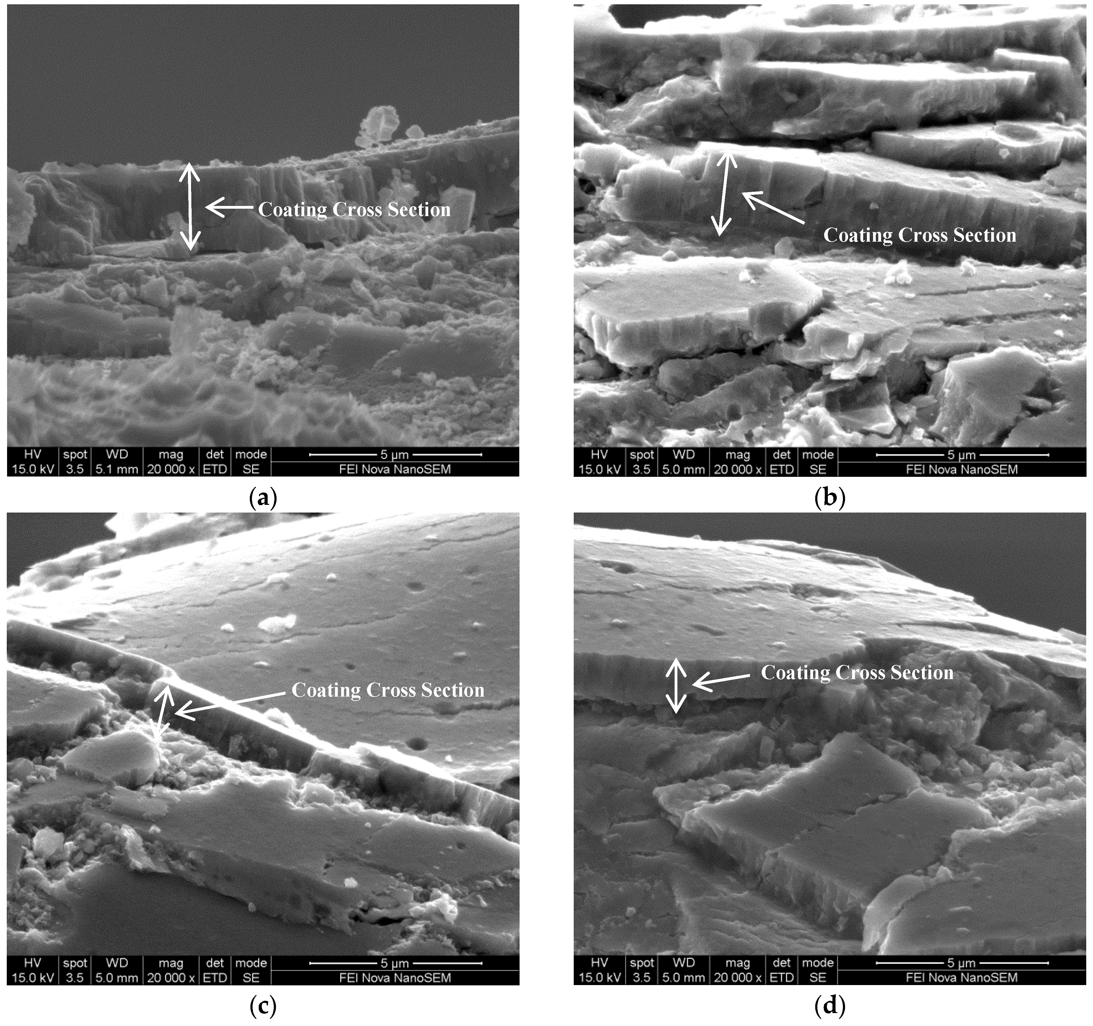
3.6.1. SEM Image of TiN Fracture Cross Sections
SEM fracture cross sections of the TiN coatings deposited using double (2R) and triple (3R) rotation configurations in both continuous and pulsed arc current mode are shown in Figure 4a–d. Here, a dense, fibrous structure was evident in the coating cross section for all four coating conditions. Little differences were observed in the cross section morphologies for all coatings. The coatings deposited using 2R rotation (Figure 4a,b) were thicker than the coatings deposited using 3R rotation (Figure 4c,d)), confirming the thickness variations provided in Table 2. The coating surfaces (Figure 4b–d), showing a slightly dimpled morphology, contained both nodular flaws and circular craters associated with larger macro-particle pull-out, associated with the poor adhesion of these nodules to the coating. These nodular surface defects have overgrowth of coating material and are not simply spherical as-deposited macro-particles. These features are consistent with morphologies of arc deposited coatings. Overall, little differences in the morphology of the TiN coatings were observed, for both DC and pulsed arc deposited coatings, deposited using both double (2R) and triple (3R) rotation configurations.
3.6.2. SEM and Optical Images of Corroded TiN Coatings
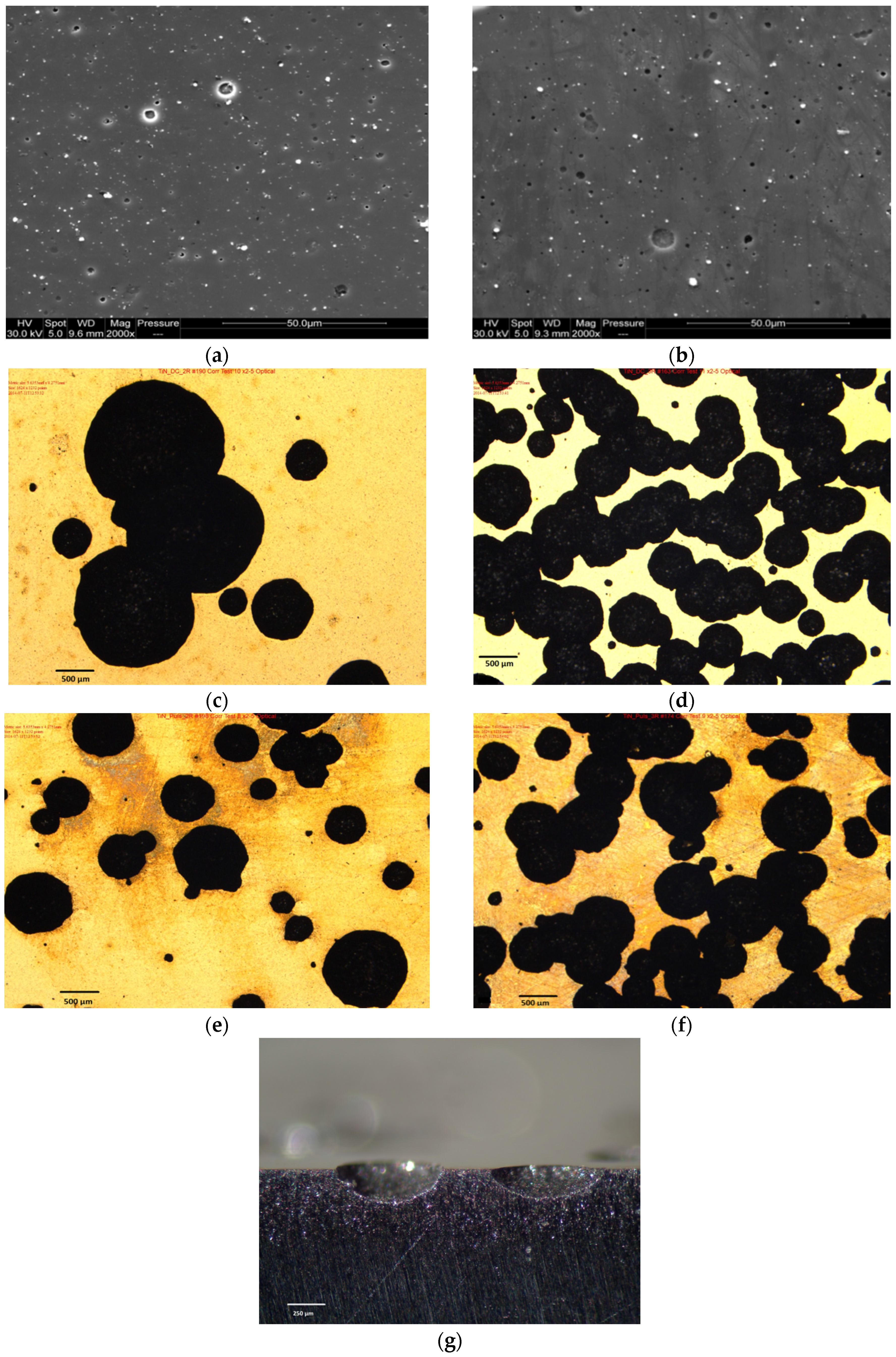
Scanning electron micrographs of the as deposited and corroded surfaces of the pulsed TiN coatings are shown in Figure 5a,b, respectively. The as deposited morphology is typical for cathodic arc PVD coatings, with surface defects due to macro-particles having characteristic diameters of 1–10 μm and nodular growth defects. Depressions or sockets are evident as circular regions with darker contrast in the SEM images, which are due to detached macro-particles. Little variation was observed in the surface characteristics of the as deposited coating surfaces deposited using conventional DC current (not shown) and pulsed arc current (Figure 5a), although there appeared to be a fewer number of defects present in the pulsed arc coating. After corrosion, however, a reduced number of macro-particles can be observed, while a greater number of sockets are further evident, as shown in Figure 5b.
Optical micrographs of the TiN coating surface topography after corrosion testing are shown in Figure 5c–f. All images were taken at the same magnification with micron bar scales shown on the photographs. Large areas of coating spallation with pitting damage were observed for both continuous and pulsed arc deposited coatings, indicating exposure of the underlying substrate. For continuous current coatings with double rotation, fewer number of pits were observed, however the diameter of these spalled regions varied from 400 μm to 2 mm, as shown in Figure 5c. In contrast, coatings deposited with triple rotation (Figure 5d) showed much higher pit density on the surface, although the diameters of these pits were lower, with typical diameters ranging from 125 to 700 μm. The pit density on these samples was such that many pits had merged together forming elongated regions of spallation. For pulsed arc coatings deposited with double rotation (Figure 5e), fewer pits with diameters ranging from 100 μm to 1 mm were observed compared with pulsed arc coatings deposited under triple rotation conditions, as shown in Figure 5f. Here, the pitting was intensified with a greater number of larger pits (1 mm diameter) merging together to form elongated regions of spallation.
Optical micrograph of a metallographic cross section of corroded TiN 2R C sample (×90 magnification) is shown in Figure 5g. Here the cross section of typical pits induced as a result of the corrosion process reveal that the pits tend to be hemispherical in nature, the pit depth at the centre being approximately one third of the pit diameter.
4. Discussion
It is widely accepted that one of the major limitations in the use of PVD metal nitride coatings as a corrosion-resistant barrier is the presence of defects such as voids and pinholes which can lead to a direct attack of the substrate by the corrosive media. This, in turn can induce a variety of problems such as galvanic coupling between the substrate and the coating, pitting, enhanced dissolution of the substrate and spallation of the coating, promoting the formation of large pits in the surface [17]. Improved performance can be achieved through the optimisation of the process deposition parameters, such as the substrate bias voltage, chamber gas pressure and sputtering target power to produce dense, pore-free, well adherent coatings with improved corrosion properties of TiN and TiAlN coatings [1].
Similarly, enhanced corrosion resistance was observed for cathodic arc deposited AlCrN and AlCrON coatings when deposited with greater film thickness and an optimised N2:O2 gas ratio of 75:25 [18]. Post deposition treatments, such as ion implantation, have been adopted as strategies for improving the corrosion resistance of nitride-based coatings [1]. In particular, coatings deposited using the cathodic arc evaporation process are known to contain large macro-particles, and hence a large driving force in the development of these coatings as corrosion-resistant barriers is to reduce the number of macro-particles present. One of the many factors that has been studied and is known to influence macro-particle formation is the arc current characteristic. Increased macro-particle density with increasing continuous DC current [19] has been reported. This was associated with increasing heat input. It was originally envisaged that increased corrosion resistance might be achieved through the use of pulsed arc technology, which may provide enhanced barrier layer performance for such coatings [16,20,21], thus providing the focus for this study.
4.1. Correlations Between the Process Deposition Conditions, Film Thickness and Surface Roughness of TiN Coatings
The study has shown that relationships exist between substrate configuration, film thickness, surface roughness and to some degree, corrosion behavior. The use of two substrate rotation configurations in this study, namely double rotation (2R) planetary and triple rotation (3R) planetary configurations, was observed to influence both the film thickness and surface roughness, which was shown to have some effect on the resultant corrosion properties. The surface roughness of the coating was found to be considerably rougher than the carbon steel substrate, which increased with increasing film thickness. This can be attributed to increasing size and number of macro-particles introduced into the coating as the thickness increases. 3R rotation configuration resulted in films of lower thickness (lower deposition rates) due to shielding from the arc evaporation source by adjacent test-pieces and jigs. Consequently, increased surface roughness was associated with the production of thicker films.
Buschel and Grimm [16] reported that a significant reduction in the number and size of droplets incorporated into cathodic arc deposited TiN and TiAlN coatings was observed when using a pulsed arc source. This was associated with increased pulse current and decreased pulse time. In contrast, the findings from the current study have shown no correlation between the surface roughness (S10z) values and the current mode for Ti cathodes at an average current of 180 A. The pulsed current source parameters used for deposition of these Ti-based coatings have not reduced the number of macro-particles formed, according to the surface roughness data.
For TiN, the crystallographic orientations, namely the (111), (200) and (220) observed from XRD analysis of the coatings, are typical of those observed elsewhere [22], although peaks associated with the (311) orientation were not observed in the current study. The similar nature of the observed orientations for both pulsed and continuous current mode would suggest that any differences in the ion energies and production of species in the plasma associated with higher peak currents during pulsing were not significant enough to induce changes in the crystallographic structure of the TiN coating.
4.2. Corrosion Behaviour of TiN Coatings
The potentiodynamic scans of TiN coatings shown in Figure 3 suggests that all the coatings have shown improved corrosion protection to the mild steel substrate, thus acting as a barrier layer between the substrate and the environment. This is evidenced by the more positive shifts in the Ecorr values and lower Icorr values of the coatings compared to the carbon steel substrate. These results are in agreement with similar findings for TiAlN and AlCrN coatings [17].
The relative resistance of the coatings is influenced by the substrate rotation configuration and the arc current mode. The more positive Ecorr values observed for coatings deposited using double rotation (2R) configuration compared with the triple rotation (3R) configuration, can be attributed to the increased film thickness associated with these coatings. Here, the slightly thicker coatings deposited using double rotation provided more noble characteristics associated with the coating, compared with the slightly thinner 3R coatings, where the more active Ecorr values may be attributed to increased contributions from the underlying substrate.
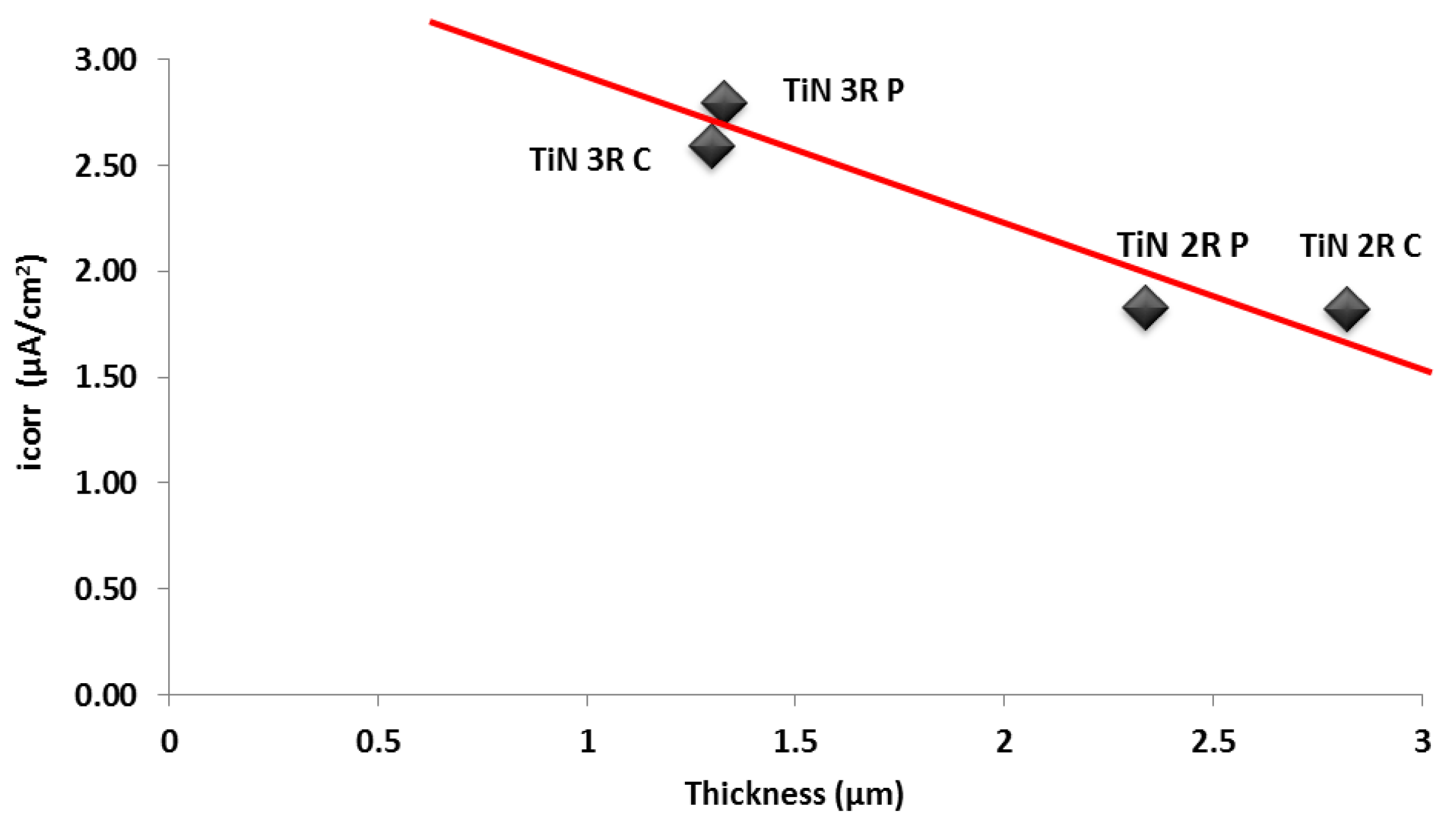
Figure 6 shows a plot of the average Icorr versus coating thickness. While the trend indicates an increased coating thickness is accompanied by a reduction in the corrosion rate (increasing average Icorr value), as shown by the trend line, the errors associated with the Icorr values make this finding inconclusive. Further work is required in this area to systematically study the effects of film thickness on the corrosion behavior of TiN coatings, as functions of current mode (pulsed or continuous) and rotation configuration (2R and 3R). The latter is particularly important for investigating the energy available for nucleation and growth of the coating and the resultant morphological changes that may occur, which may influence the corrosion behavior.
However, it should be emphasised that the reported Icorr values only serve as an indication of relative behaviour within the free corroding potential region. At higher anodic potentials, approaching +500 mV as shown in Figure 3, the anodic curves of three coatings are identical to the anodic curve of the carbon steel. This suggests that at higher oxidising potentials, the coatings are no longer protective, resulting in coating breakdown and severe localised corrosion of the substrate at these breakdown points. Under these conditions, the anodic corrosion characteristic of the coating system is more closely aligned with the corrosion characteristics of the mild steel substrate. It should be noted that the anodic curves for the double rotation continuous coatings did not approach that of the carbon steel, double rotation pulsed and both triple rotation coatings, but exhibited lower current values at +500 mV. This suggests improved corrosion resistance of the thicker, continuous current deposited coatings at higher anodic potentials.
4.3. Morphological Effects on the Corrosion Behaviour of TiN Coatings
The optical and scanning electron micrographs provide an insight into the mechanisms that control the extent of corrosion occurring in the coatings. The reduced number of macro-particles and the increased number of voids observed on the coating surfaces after corrosion suggests that macro-particle detachment during the corrosion process is important in the corrosion mechanism (Figure 5a,b). The voids produced due to macro-particle detachment may act as initiation sites for pitting of the substrate since regions of the substrate are then exposed to the corrosive media. Therefore, the presence of defects, pinholes and macro-particles, before and after the corrosion process, become the limiting factors which control the corrosion behaviour of the coating system at lower anodic potentials.
After corrosion testing, the extremely large corroded regions exhibiting severe pitting with corrosion localised at the exposed substrate, as shown in the optical micrographs (Figure 5c–f), suggest that at the higher potentials approaching +500 mV the observed corrosion characteristics are possibly influenced by the presence of large areas of exposed substrate due to coating spallation being observed on the corroded coating surfaces, confirming that the corrosion behaviour of the coating system is predominantly controlled by the corrosion behaviour of the mild steel substrate as pitting commences. Further, it is postulated that the mechanism for production of these large corroded regions is existing pinholes, which can act as initiation sites for accelerated, localised (pitting) corrosion to occur and macro-particles can become detached during corrosion, providing large voids for further corrosion to initiate and propagate. The production of these corrosion sites within any one region can then result in the removal of the underlying substrate to the point that the steel can no longer support the coating, which in turn, cracks and spalls away. This then allows the coating system to corrode as freely as the mild steel alone [18].
Cross sections of the pits observed in Figure 5g are consistent with the formation of wide shallow pits, where the pit depth at the centre (maximum) is approximately one third of the pit diameter. This would suggest that metal dissolution is higher at the walls of the pit than at the bottom of the pit. The absence of any pit morphologies showing undercutting or subsurface pitting suggests that once the pit has initiated and has become stable, then the coating is being removed at the same rate as the pit is growing, thus ensuring that all of the pit area is exposed to the corrosive media.
It is suggested that coating removal within the pit region may occur either by chemical dissolution, mechanical removal or a combination of both. Pit formation may be initiated by chemical dissolution of the coating either at an existing defect or elsewhere on the surface, thus exposing more of the underlying steel substrate to attack. Conversely, the dissolution of the steel substrate at existing defects may result in regions of the coating which cannot support themselves and thus are prone to cracking and spallation. Removal of the coating would have to occur at the same rate that a pit grows in order to maintain the hemispherical morphology. It is unclear which of these mechanisms dominate, thus providing a basis for future studies in this area.
The increased number of pits observed on the surface of the 3R C and 3R P TiN coatings indicates the increased likelihood of breakdown and susceptibility to pitting under high anodic polarization conditions, which is governed predominantly by the substrate rotation configuration which promotes thinner films. While pit size/pit density was virtually independent of the arc current mode at triple rotation configuration, at double rotation configuration, fewer, larger pits were observed under continuous arc current mode (2R C) compared to pulsed arc current mode (2R P). The presence of fewer pits for 2R C coatings plus lower anodic currents at +500 mV serves as an indication of the more protective nature of these coatings under strong anodic polarization conditions.
The effect of coating integrity on the effectiveness of corrosion barrier layer systems has been demonstrated for other deposition techniques on mild steel, e.g., in the case of tungsten carbide (WC) based cermet coatings [23]. The poor corrosion protection was attributed to a poor coating structure featuring high porosity levels and the presence of micro-cracks within the coating. It was further observed that these micro-cracks provided a direct path from the environment to the substrate, inducing galvanic coupling effects between the substrate and the coating, resulting in enhanced dissolution and increased void/micro-crack formation. In the current study, if macro-particle detachment resulted in exposed regions of the substrate, enhanced dissolution of the substrate may have occurred due to galvanic effects between the substrate and the coating.
It is likely that for the thicker films deposited under continuous arc current conditions, there is a lower probability that the substrate will become exposed to the media and thus a lower probability of stable pits initiating at these sites, thus explaining why thicker films have fewer areas of large pits. However, the reduced corrosion resistance of the pulsed coatings cannot be explained by this mechanism.
Overall, while reduced corrosion can be controlled by having reduced number of pinholes and macro-particles during the deposition of the coatings at the microstructural level, enhanced corrosion resistance is favoured by structures which can restrict the initiation, formation and growth of the large regions of coating spallation and underlying substrate corrosion. The differences between the microstructures, composition and stress state of the experimental coatings deposited using a pulsed arc current source will be the subject for further study.
In addition, the main purpose of using potentiodynamic scanning and Tafel extrapolation was to provide an overall comparative study of the electrochemical corrosion behaviour of the coated steel samples, compared with the uncoated steel samples, when exposed to a saline environment. As a consequence of these scans, particularly at higher anodic potentials, breakdown of the coating at isolated regions and attack of the underlying substrate occurred, giving the appearance of localized corrosion. In order to assess the localized corrosion behavior of these coating systems, more appropriate electrochemical techniques should be employed and this forms the basis for future work in this area.
As shown in this study, increased surface roughness, and to a certain extent, corrosion resistance, was associated with thicker coatings deposited using 2R rotation configuration compared to 3R. In order to determine inherent effects associated with the arc current mode and substrate rotation configuration (outside of film thickness) on surface roughness and corrosion resistance, coatings for all test conditions should be deposited with equal film thickness and evaluated accordingly. As part of these studies, focus should be given to the formation, growth and distribution of defects within the coating in order to assess their role and influence on the corrosion behavior of the coatings.
5. Conclusions
- The deposition of TiN coatings resulted in less negative Ecorr and lower Icorr values, determined from Tafel Extrapolation, when compared with the mild steel substrate after potentiodynamic corrosion testing in 3.5% NaCl.
- Coatings deposited under double rotation (2R) configuration showed more noble (more positive Ecorr values) characteristics than those deposited under triple rotation (3R) configuration. This was attributed to the increased film thickness of the 2R coatings. Any correlations between substrate rotation configuration, arc current mode and observed Icorr values were inconclusive from this study and further work is required in this area.
- At high anodic potentials approaching +500 mV, the corrosion behaviour of most coating systems (except 2R C) was characteristic of uncoated mild steel. This suggests that the limiting factors controlling the corrosion behaviour of the coating system at lower anodic potentials were the presence of defects, pinholes and macro-particles. The initiation, formation and growth of large pitted regions with further coating spallation resulted in underlying substrate corrosion which became the dominant factors at higher anodic potentials.
- An increased number of pits were observed for thinner coatings deposited by triple rotation (both 3R C and 3R P). Fewer, but larger, pits were observed for 2R C coatings, indicating an increased resistance to breakdown at higher anodic potentials.
- Surface roughness from FVM measurements was found to increase with increasing film thickness, although no correlation was found with the type of arc current (continuous or pulsed) in the study.
- The effects of coating microstructure, composition, residual stress and film thickness on the reduced corrosion performance of coatings deposited using pulsed arc current techniques requires further investigation. This will include the deposition of coatings with similar film thicknesses to determine the effects of arc current mode and substrate rotation configuration on the resultant properties, with a focus on coating formation, growth and distribution of defects and their influence on the corrosion behavior.
Acknowledgments
This body of work was undertaken by the DMTC with researchers from RMIT University and Sutton Tools Pty. Ltd. The DMTC was established and is supported by the Australian Government’s Defence Future Capability Technology Centre (DFCTC) initiative. The industrial DMTC partner Sutton Tools Pty. Ltd. provided sponsorship, research materials and supported the coating deposition facilities. The authors acknowledge the facilities, and the scientific and technical assistance, of the Australian Microscopy & Microanalysis Research Facility at the RMIT Microscopy & Microanalysis Facility, at RMIT University.
Author Contributions
L. Ward, A. Pilkington and S. Dowey conceived and designed the experiments; L. Ward, A. Pilkington and S. Dowey performed the experiments; L. Ward, A. Pilkington and S. Dowey analyzed the data; S. Dowey contributed reagents/materials/analysis tools; L. Ward and A. Pilkington wrote the paper.
Conflicts of Interest
The authors declare no conflict of interest. The funding sponsors had no role in the design of the study; in the collection, analyses, or interpretation of data; in the writing of the manuscript, and in the decision to publish the results.
References
- Ward, L.P. Studies on the Corrosion behaviour of a selection of metal nitride coatings and the effect of surface modification. In Proceedings of the Corrosion and Prevention Conference 2009 (CAP09), Coffs Harbour, NSW, Australia, 15–18 November 2009. [Google Scholar]
- Liu, C.; Bi, Q.; Leyland, A.; Matthews, A. An electrochemical impedance spectroscopy study of the corrosion behaviour of PVD coated steels in 0.5 N NaCl aqueous solution: Part I. Establishment of equivalent circuits for EIS data modelling. Corr. Sci. 2003, 45, 1243–1256. [Google Scholar] [CrossRef]
- Navinsek, B.; Panjan, P.; Milosev, I. PVD coatings as an environmentally clean alternative to electroplating and electroless processes. Surf. Coat. Technol. 1999, 116–119, 476–487. [Google Scholar] [CrossRef]
- Cunha, L.; Andritschky, M.; Rebouta, L.; Pischow, K. Corrosion of CrN and TiAlN coatings in chloride-containing atmospheres. Surf. Coat. Technol. 1999, 116–119, 1152–1160. [Google Scholar] [CrossRef]
- Cunha, L.; Andritschky, M.; Pischow, K.; Wang, Z. Microstructure of CrN coatings produced by PVD techniques. Thin Solid Films 1999, 355–356, 465–470. [Google Scholar] [CrossRef]
- Constantin, R.; Miremad, B. Performance of hard coatings, made by balanced and unbalanced magnetron sputtering, for decorative applications. Surf. Coat. Technol. 1999, 120–121, 728–733. [Google Scholar] [CrossRef]
- Wang, Q.; Zhou, F.; Zhou, Z.; Li, L.K.-Y.; Yan, J. Electrochemical performance of TiCN coatings with low carbon concentration in simulated body fluid. Surf. Coat. Technol. 2014, 253, 199–204. [Google Scholar] [CrossRef]
- Antunes, R.A.; de Assis, S.L.; Lorenzetti, S.G.; Higa, O.Z.; Costa, I. Comparison of in vitro corrosion behaviour and biocompatibility of Ti-13Zr-13Nb and passivated 316L stainless steel coated with TiCN. In Proceedings of the COBEM, 18th International Conference of Mechanical Engineering, Ouro Preto, MC, Brazil, 6–11 November 2005. [Google Scholar]
- Massiani, Y.; Medjahed, A.; Crousier, JP.; Gravier, P.; Rebatel, I. Corrosion of sputtered titanium nitride films deposited on iron and stainless steel. Surf. Coat. Technol. 1991, 45, 115–120. [Google Scholar] [CrossRef]
- Piippo, J.; Elsener, B.; Bohni, H. Electrochemical characterisation of TiN coatings. Surf. Coat. Technol. 1993, 61, 43–46. [Google Scholar]
- Brown, R.; Alias, M.N.; Fontana, R. Effect of composition and thickness on corrosion behaviour of TiN and ZrN thin films. Surf. Coat. Technol. 1993, 62, 467–473. [Google Scholar] [CrossRef]
- Kazuhisa, A.; Shigeyo, W.; Masahiro, S.; Isao, S.; Yokio, I.; Patrick, J.; William, S. Characterization of anodic oxide film formed on TiN coating in neutral borate buffer solution. Corr. Sci. 1998, 40, 1363–1377. [Google Scholar]
- Massiani, Y.; Medjahed, A.; Gravier, P.; Argeme, L.; Fedrizzi, L. Electrochemical study of titanium nitride films obtained by reactive sputtering. Thin Solid Films 1990, 191, 305–316. [Google Scholar] [CrossRef]
- Wang, H.W.; Stack, M.M.; Lyon, S.B.; Hovsepian, P.; Munz, W.-D. Preferential wear of droplet defects for combined cathodic arc-unbalanced magnetron sputtering CrN/NbN superlattice coatings during erosion in alkaline slurries. J. Mater. Sci. Lett. 2001, 20, 1995–1997. [Google Scholar] [CrossRef]
- Pilkington, A. Development and Evaluation of Plasma-Assisted Alumina Based Coatings. Ph.D. Thesis, University of Sheffield, Sheffield, UK, 2014. [Google Scholar]
- Büschel, M.; Grimm, W. Influence of the pulsing of the current of a vacuum arc on rate and droplets. Surf. Coat. Technol. 2001, 142–144, 665–668. [Google Scholar] [CrossRef]
- Ward, L.P.; Pilkington, A.; Dowey, S.J.; Doyle, E.D. Corrosion Properties of Cathodic Arc Evaporated Coatings. In Proceedings of the Corrosion and Prevention Conference 2014, CAP14, Darwin, NT, Australia, 21–24 September 2014. [Google Scholar]
- Ward, L.P.; Pilkington, A.; Dowey, S.J.; Toton, J.T.; Doyle, E.D. Studies on the corrosion behaviour of AlCrON coatings. In Proceedings of the Corrosion and Prevention Conference 2013, CAP13, Brisbane, QLD, Australia, 12–15 Nobember 2013. [Google Scholar]
- Hu, Y.; Li, L.; Dai, H.; Li, X.; Cai, X.; Chu, P.K. Effects of pulse parameters on macro-particle production in pulsed cathodic vacuum arc deposition. Surf. Coat. Technol. 2007, 201, 6542–6544. [Google Scholar] [CrossRef]
- Ramm, J.; Ante, M.; Bachmann, T.; Widrig, B.; Brändle, H.; Döbeli, M. Pulse enhanced electron emission (P3e™) arc evaporation and the synthesis of wear resistant Al–Cr–O coatings in corundum structure. Surf. Coat. Technol. 2007, 202, 876–883. [Google Scholar] [CrossRef]
- Fuchs, H.; Engers, B.; Hettkamp, E.; Mecke, H.; Schultz, J. Deposition rate and thickness uniformity of thin films deposited by a pulsed cathodic arc process. Surf. Coat. Technol. 2001, 142–144, 655–660. [Google Scholar] [CrossRef]
- Devia, D.M.; Restrepo-Parra, E.; Arango, P.J. Comparative study of titanium carbide and nitride coatings grown by cathodic vacuum arc technique. App. Surf. Sci. 2011, 258, 1164–1174. [Google Scholar] [CrossRef]
- Ward, L.P.; Biddle, G.; Hinton, B.; Gerrard, D. Characterisation and evaluation of the corrosion behaviour of modified HVOF sprayed WC based coatings deposited on AISI 1020 mild steel substrates. In Proceedings of the Corrosion and Prevention Conference 2006 (CAP06), Hobart, Tasmania, Australia, 19–22 November 2006. [Google Scholar]
Figure 1.
Schematic diagram showing 1 kHz pulsed arc waveform.
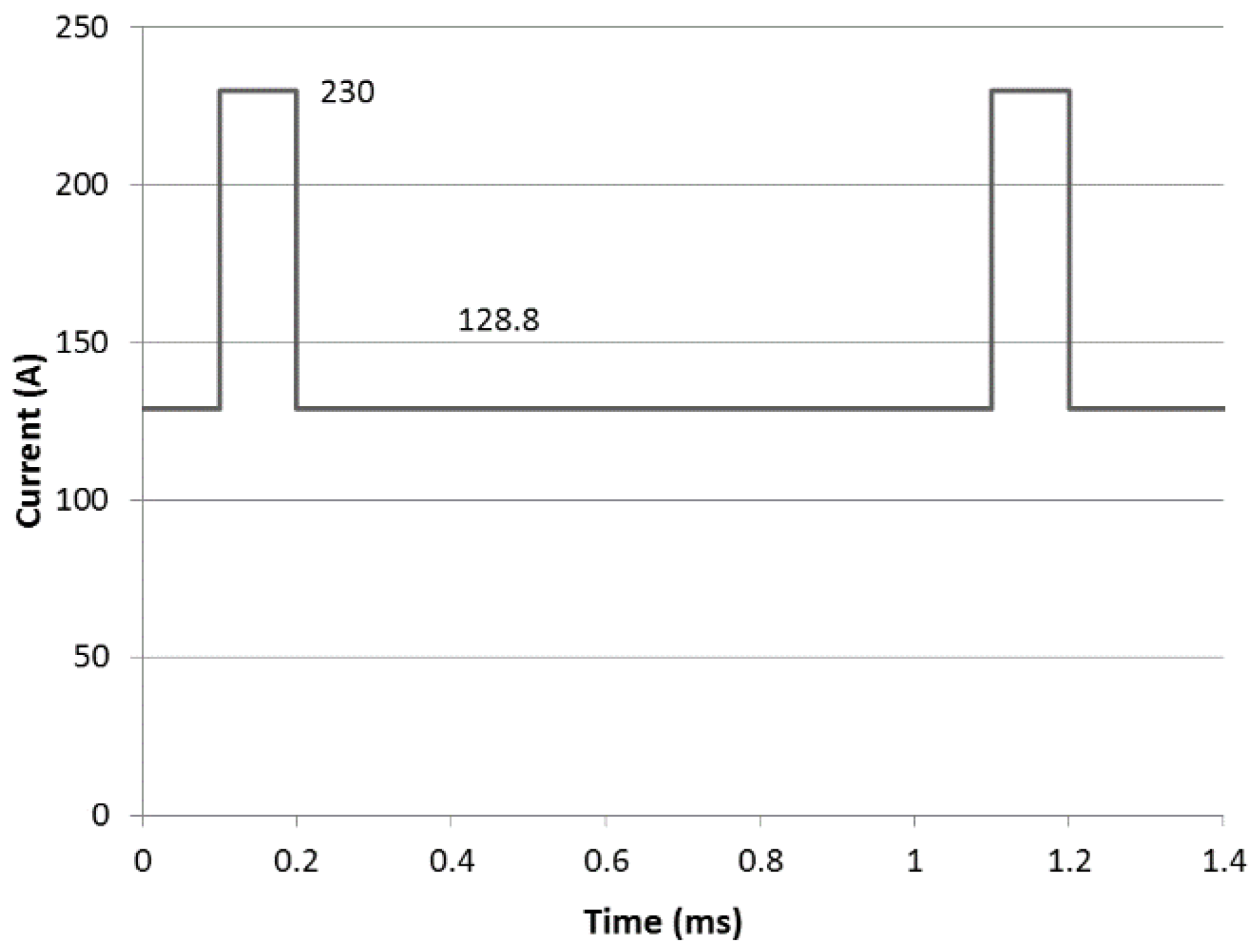
Figure 2.
XRD spectra for cathodic arc evaporated TiN coatings.
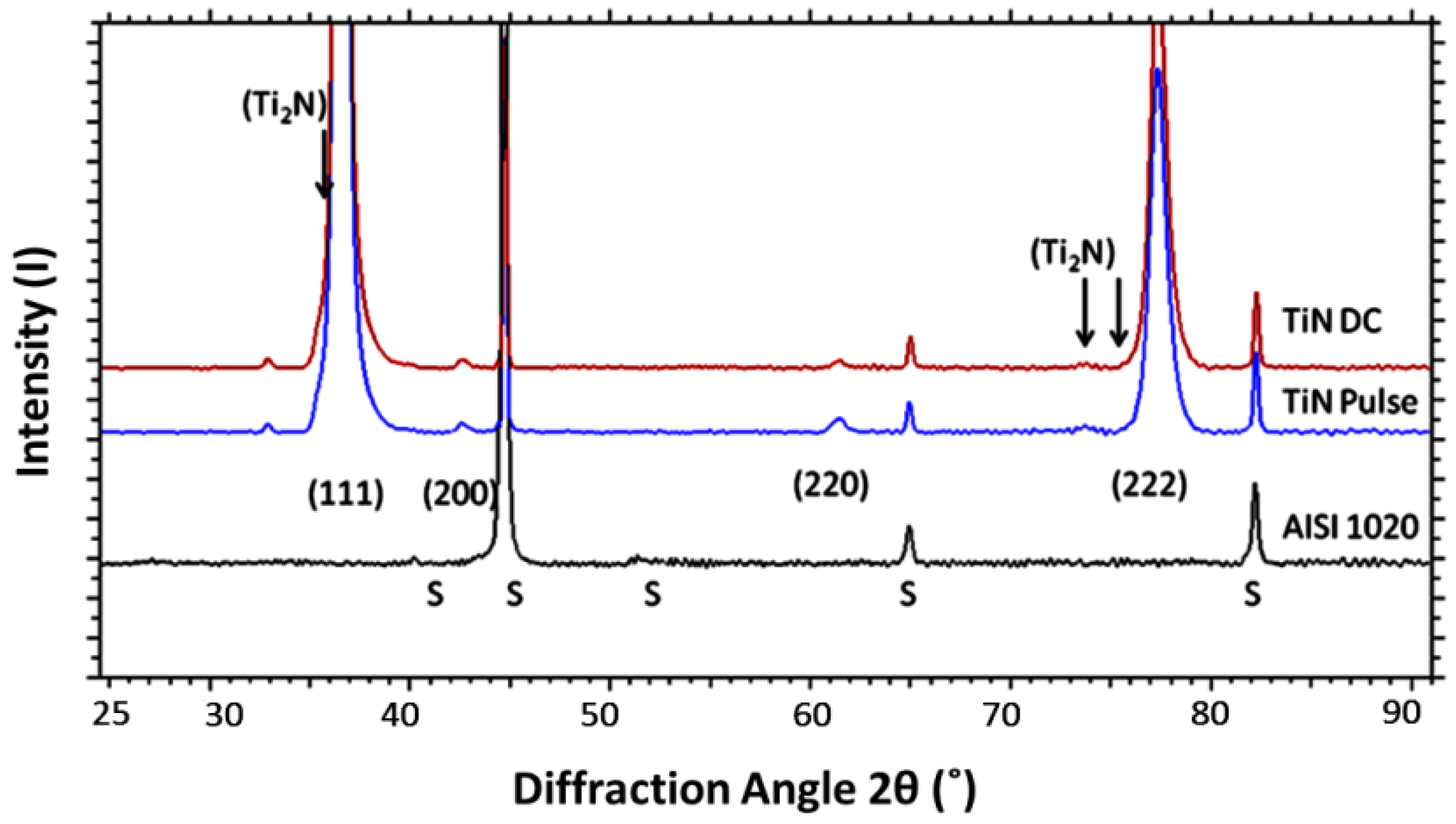
Figure 3.
Potentiodynamic scans for continuous and pulsed arc current TiN coatings in 3.5% NaCl.
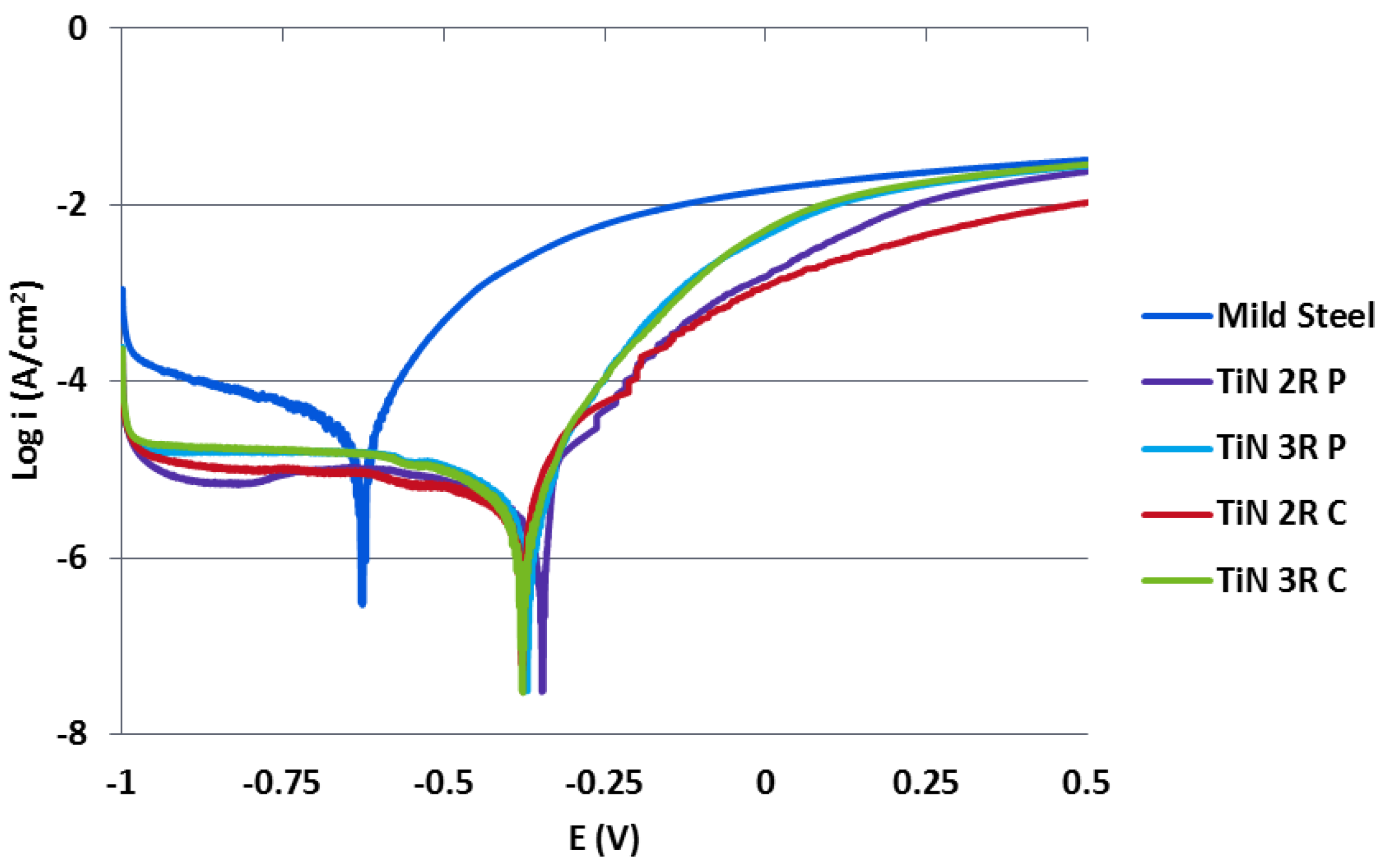
Figure 4.
SEM fracture cross sections of (a) TiN 2R C; (b) TiN 2R P; (c) TiN 3R C; (d) TiN 3R P arc deposited coatings.
Figure 4.
SEM fracture cross sections of (a) TiN 2R C; (b) TiN 2R P; (c) TiN 3R C; (d) TiN 3R P arc deposited coatings.

Figure 5.
Micrographs showing (a) SEM image of the as deposited surface of TiN 3R P; (b) SEM image of the corroded surface of TiN 3R P; (c) optical image of the corroded surface of TiN 2R C; (d) optical image of the corroded surface of TiN 3R C; (e) optical image of the corroded surface of TiN 2R P; (f) optical image of the corroded surface of TiN 3R P; (g) optical image of corroded cross section of TiN 2R C showing pits.

Figure 6.
Plot of Icorr against physical vapour deposited (PVD) coating thickness


Table 1.
Deposition details of conventional and pulsed TiN coatings.
| Coating | Arc Current (A) | Pulse Duty Cycle, Frequency |
|---|---|---|
| TiN 2R C | 180 | n/a |
| TiN 3R C | 180 | n/a |
| TiN 2R P | 230/128.8 | 10%, 1 kHz |
| TiN 3R P | 230/128.8 | 10%, 1 kHz |
Table 2.
Coating thickness, surface roughness and evaporation rate values for conventional and pulsed TiN coatings.
Table 2.
Coating thickness, surface roughness and evaporation rate values for conventional and pulsed TiN coatings.
| Coating | Coating Thickness (μm) | Deposition Rate (nm/s) | Evaporation Rate (mg/s) | Evaporation Efficiency (g/C) | Surface Roughness Sq (nm) | Surface Roughness S10z (μm) |
|---|---|---|---|---|---|---|
| AISI 1020 | – | – | – | – | 14.7 ± 3.9 | 0.234 ± 0.02 |
| TiN 2R C | 2.8 ± 0.1 | 0.78 | 3.47 | 2.17 × 10⁻⁵ | 180.83 ± 15.47 | 3.52 ± 0.39 |
| TiN 3R C | 1.3 ± 0.1 | 0.36 | – | – | 126.36 ± 12.93 | 1.93 ± 0.46 |
| TiN 2R P | 2.3 ± 0.1 | 0.64 | 2.97 | 2.05 × 10⁻⁵ | 187.37 ± 2.51 | 3.06 ± 0.41 |
| TiN 3R P | 1.3 ± 0.1 | 0.37 | – | – | 137.74 ± 4.33 | 1.91 ± 0.34 |
Table 3.
Ecorr and Icorr values for conventional and pulsed TiN coatings.
| Coating | Ecorr (mV) | Icorr (µA/cm2) |
|---|---|---|
| 1020 Carbon Steel | −626 ± 3 | 15.57 ± 6.04 |
| TiN 2R C | −350 ± 41 | 1.82 ± 1.08 |
| TiN 3R C | −399 ± 32 | 2.59 ± 1.18 |
| TiN 2R P | −357 ± 13 | 1.83 ± 0.36 |
| TiN 3R P | −376 ± 6 | 2.80 ± 0.99 |
© 2017 by the authors. Licensee MDPI, Basel, Switzerland. This article is an open access article distributed under the terms and conditions of the Creative Commons Attribution (CC BY) license (http://creativecommons.org/licenses/by/4.0/).
Share and Cite
MDPI and ACS Style
Ward, L.; Pilkington, A.; Dowey, S. Studies on the Effect of Arc Current Mode and Substrate Rotation Configuration on the Structure and Corrosion Behavior of PVD TiN Coatings. Coatings 2017, 7, 50. https://doi.org/10.3390/coatings7040050
AMA Style
Ward L, Pilkington A, Dowey S. Studies on the Effect of Arc Current Mode and Substrate Rotation Configuration on the Structure and Corrosion Behavior of PVD TiN Coatings. Coatings. 2017; 7(4):50. https://doi.org/10.3390/coatings7040050
Chicago/Turabian StyleWard, Liam, Antony Pilkington, and Steve Dowey. 2017. "Studies on the Effect of Arc Current Mode and Substrate Rotation Configuration on the Structure and Corrosion Behavior of PVD TiN Coatings" Coatings 7, no. 4: 50. https://doi.org/10.3390/coatings7040050
Note that from the first issue of 2016, this journal uses article numbers instead of page numbers. See further details here.