
Application of High-Velocity Oxygen-Fuel (HVOF) Spraying to the Fabrication of Yb-Silicate Environmental Barrier Coatings


1
Forschungszentrum Jülich GmbH, Institute of Energy and Climate Research (IEK-1), 52425 Jülich, Germany
2
German Aerospace Center, Institute of Structures and Design, 70569 Stuttgart, Germany
*
Author to whom correspondence should be addressed.
Coatings 2017, 7(4), 55; https://doi.org/10.3390/coatings7040055
Submission received: 22 February 2017
/
Revised: 9 April 2017
/
Accepted: 12 April 2017
/
Published: 18 April 2017
(This article belongs to the Special Issue Thermal Spray Technology)
Abstract
:From the literature, it is known that due to their glass formation tendency, it is not possible to deposit fully-crystalline silicate coatings when the conventional atmospheric plasma spraying (APS) process is employed. In APS, rapid quenching of the sprayed material on the substrate facilitates the amorphous deposit formation, which shrinks when exposed to heat and forms pores and/or cracks. This paper explores the feasibility of using a high-velocity oxygen-fuel (HVOF) process for the cost-effective fabrication of dense, stoichiometric, and crystalline Yb2Si2O7 environmental barrier coatings. We report our findings on the HVOF process optimization and its resultant influence on the microstructure development and crystallinity of the Yb2Si2O7 coatings. The results reveal that partially crystalline, dense, and vertical crack-free EBCs can be produced by the HVOF technique. However, the furnace thermal cycling results revealed that the bonding of the Yb2Si2O7 layer to the Silicon bond coat needs to be improved.
1. Introduction
Silicon carbide (SiC) fiber reinforced SiC ceramic matrix composites (CMCs), having a relatively low density and higher temperature capability compared to their metallic superalloy counterparts, are notable materials for the future of gas turbine engine technology. A significant enhancement in gas turbine efficiency leading to lower fuel consumption and a lower emission of NOx are anticipated with the implementation of CMCs in the gas turbine engines [1,2,3,4,5].
However, the lack of durable CMCs in combustion environments interferes with this implementation, as water vapor reacts with the silica scale that forms on the CMCs, leading to the formation of gaseous reaction products such as Si(OH)4 [4,6]. An enhanced recession rate of the CMCs in high pressure and high gas velocity combustion atmospheres reveals the requirement of protective environmental barrier coatings (EBCs) for their long-term use under these conditions [7,8,9]. The establishment of environmentally stable (i) and well-adhering coatings on the CMC substrate (ii) that have a chemical compatibility within the layers (iii), and that develop minor stresses as a result of thermal expansion mismatch and phase transformations etc. (iv) are desired for this purpose [10].
EBC systems consisting of a silicon bond coat and a rare-earth (RE) silicate (e.g., Yb2Si2O7, Lu2Si2O7) top coat layer were successfully tested in gas turbine engines [10,11,12,13,14]. In these EBC systems, RE-silicates with a high water vapor stability impede the diffusion of oxygen and water vapor to the substrate. In the meantime, the silicon bond coat plays an important role in the oxidation protection of the substrate, as well as for the adhesion of the coating on the substrate. While the RE-silicates were shown to be promising, the fabrication of crystalline and single-phase silicate coatings with a dense microstructure has been troublesome when using the conventional plasma spraying process. Modification in the plasma spraying process was thus proposed, suggesting the utilization of a furnace in which the substrate to be deposited is placed and heated up to 1200 °C [15]. By this adjustment, the deposition of dense and crystalline RE-silicate coatings was found to be ensured, yet, secondary phases in the coatings as a result of the evaporation of Si-containing species could not be avoided [16]. Furthermore, the feasibility and adaptation of such a process involving a furnace for the big and complex-shaped components are questionable. In a recent study [17], it was reported, based on initial trials, that the HVOF process can be an alternative method to achieve dense Yb2Si2O7 coatings with desired properties. This is because, in contrast with the APS process, HVOF offers a low heat transfer to the particles (flame temperatures up to 3000 °C), reducing the molten fraction of the sprayed powders which is expected to be favorable for obtaining crystalline and stoichiometric coatings. Moreover, the high particle velocities achieved in HVOF typically provide well-bonded particles resulting in high-density coatings. To this end, we further investigated the HVOF processing of Yb2Si2O7 coatings and address our findings in this study in terms of process optimization, microstructure, composition, and crystallinity. The crystallinity, as well as the adhesion of the Yb2Si2O7 coatings on the Si bond coat, are discussed in relation to the feedstock particle size and the furnace thermal cycling behavior of a Si/Yb2Si2O7 EBC system is reported.
2. Experimental Procedure
2.1. Materials and Process
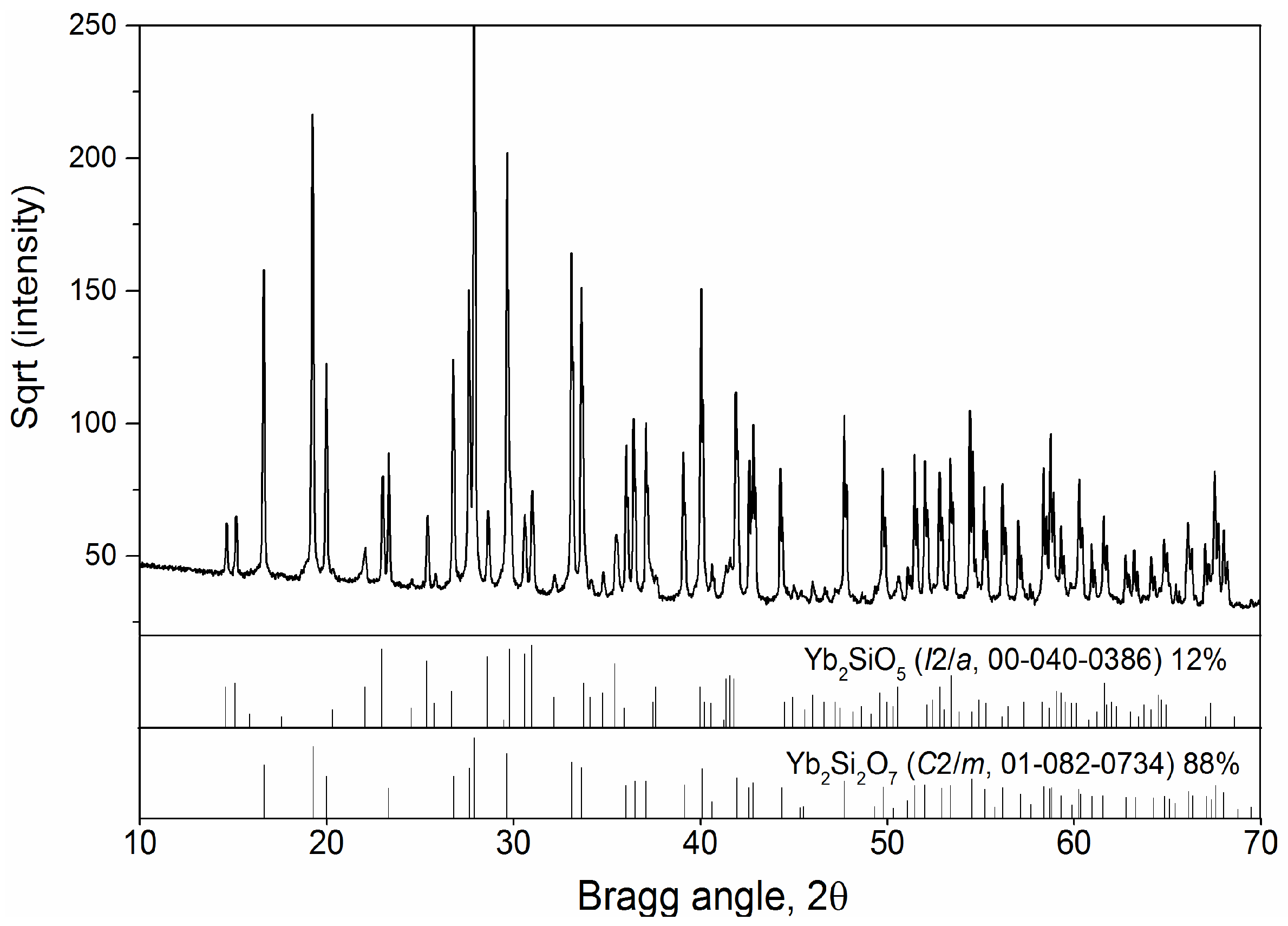
Commercially available Si and Yb2Si2O7 powders provided by Oerlikon Metco (US) Inc. (New York, NY, USA) were used in this study. The details about the two kinds of powders are given in Table 1. The elemental analysis of the Si powder, determined by inductively coupled plasma optical emission spectroscopy (ICP-OES, TJA-Iris-Intrepid, Thermo Scientific GmbH, Kleve, Germany), revealed 98.7 wt % ± 0.7 wt % purity. The phase composition of the Yb2Si2O7 feedstock was determined with an X-ray diffractometer (XRD, D4 Endeavor, Bruker AXS GmbH, Karlsruhe, Germany) (Cu Kα radiation, operating voltage 40 kV, current 40 mA, step size 0.02°, step time 0.75 s) over a 2θ-range of 10°–80°. The deconvolution of the XRD peaks for quantitative phase analysis was performed using Rietveld analysis (TOPAS Software, Bruker AXS GmbH, Karlsruhe, Germany). The XRD analysis of the Yb2Si2O7 powder, as shown in Figure 1, yielded a crystalline structure with the presence of monoclinic Yb2Si2O7 (C2/m, JCPDS No 01-082-0734) and secondary monoclinic Yb2SiO5 (I2/a, JCPDS No 00-040-0386) phases. According to the Rietveld analysis, the powder was found to contain 88 wt % and 12 wt % Yb2Si2O7 and Yb2SiO5, respectively.
Diamond Jet 2700 high-velocity oxy-fuel spraying equipment (Oerlikon-Metco, Wohlen, Switzerland) and a three-cathode TriplexPro-210 APS gun (Oerlikon-Metco, Wohlen, Switzerland) manipulated with a six-axis robot (IRB 2400, ABB, Zürich, Switzerland) in a Multicoat facility (Oerlikon-Metco, Wohlen, Switzerland) were used to fabricate the Yb2Si2O7 and Si coatings, respectively. The HVOF burner was fitted with a convergent cylindrical design nozzle (Type 2705) which yields lower particle velocities and thus longer dwell times in comparison to that of a convergent-divergent nozzle [18]. Methane has been used as the fuel gas in the HVOF process. For the optimization of the HVOF spraying conditions, the methane/oxygen ratios and stand-off distances (SOD) were varied. The flow rate of the methane was selected to be 190, 200, 215 slpm, whereas the oxygen flow rate was kept constant, at its maximum possible value of 395 slpm for the equipment. The more detailed spraying parameters used in the present study are listed in Table 2 and Table 3. Ferritic stainless steel (20 × 20 mm2) substrates were used for the initial spraying optimization of the Yb2Si2O7 coatings. The substrates were alumina grit blasted with an average particle size of 45–125 µm using 3 bar pressure for 20 s to reach an average roughness of 3.9 ± 0.1 µm. For the calculation of the area specific weight (g/m2) of the Yb2Si2O7 coatings, the area of each substrate was measured and the weight of each sample was recorded before and after spraying (using five spraying cycles). In order to evaluate the splat morphologies, single splats of the Yb2Si2O7 were produced via a wipe test on single-side polished silicon wafers. The surface morphology of the splats was afterward measured by a 3D laser confocal microscope (Keyence VK-9700, Keyence, Osaka, Japan). For furnace cycling, SiC/SiCN CMC substrates provided by DLR Stuttgart [19] were coated with the optimized Si/Yb2Si2O7 EBC system.
2.2. Calculations of Gas Temperature and Velocity in the HVOF Nozzle
Chemical Equilibrium and Applications (CEA) [20] software was used to calculate the gas temperature and velocity in the nozzle throat using an infinite-area combustion chamber model. In this one-dimensional model, the combustion conditions are obtained with the assumption of the chemical equilibrium of the combustion products. Further details of the model’s assumptions, parameters, and procedures for obtaining the combustion and throat conditions can be found in the report of Gordon and McBride [20].
The calculations were made for three different oxygen/methane flow rate combinations (#1, #2 and #3 in Table 2). The individual nozzle entry pressure input for each oxygen/methane combination was located by iteration, according to the condition of the constant mass flow rate (ṁ, kg/s),
where , A, and u are the gas density (kg/m3), nozzle cross-sectional area (m2), and gas velocity (m/s), respectively. of the gas mixture and A of the nozzle throat (= 7 mm) were known in this equation, while and u of the gas mixture at the throat of the nozzle were calculated by the software for a given chamber pressure. After the nozzle entry pressures were correctly located for each mixture, the gas velocity and temperatures were finally calculated at the throat of the nozzle, which corresponds to the nozzle exit conditions.
2.3. Characterization of the Coatings
The microstructures of the as-sprayed and thermally cycled coatings were analyzed using a scanning electron microscope (SEM, TM3030, Hitachi High-Technologies, Chiyoda, Tokyo, Japan) coupled with an energy dispersive X-ray spectrophotometer (EDX, Quantax70, Bruker Nano GmbH, Berlin, Germany); secondary electron (SE) and backscattered electron (BSE) signals were collected. Acquired BSE-SEM images were also employed to assess the volume fractions of pores in the coatings by image analysis, using an image thresholding procedure with the analySIS pro software (Olympus Soft Imaging Solutions GmbH, Münster, Germany). The analysis was performed on 10 SEM micrographs (×2000 magnification) per sample, each having a resolution of 1280 × 1100 pixels and covering a horizontal field width of 126 µm. A metallographic cross-section of an as-sprayed coating was also investigated with FEG-SEM (LEO Gemini 1530 from Carl Zeiss NTS GmbH, Oberkochen, Germany) equipped with an electron backscatter diffraction (EBSD) detector (NordlysNano, Oxford Instruments, Oxfordshire, UK) to demonstrate the amorphous and crystalline areas, as well as to generate a phase map of the crystalline regions.
The phase composition of the coatings was determined with the same measurement parameters for the feedstock given above (D4 Endeavor, Bruker AXS GmbH, Karlsruhe, Germany). The PONKCS (partial or no known crystal structure) method was used to determine the amorphous content of the as-sprayed coatings using the XRD data, as described in the previous work [17]. Further details about the procedure can also be found in [21].
The roughness (arithmetic mean deviation of the surface, Ra) of the substrates and the as-sprayed coatings was measured with an optical profilometer using a chromatic white light sensor (CHR 1000) (CyberScan CT 300, CyberTechnologies, Ingolstadt, Germany). An evaluation of the roughness measurements was made in accordance with the recommendations of the standards DIN EN ISO 4288 [22] and DIN EN ISO 3274 [23]. Accordingly, the cut-off wavelength (λc) was selected, depending on the expected roughness values. At the same time, the evaluation length (In) and the corresponding traverse length (It) were defined, according to the standards.
2.4. Furnace Thermal Cycling Test
The Si/Yb2Si2O7 EBCs deposited on the SiC/SiCN substrates were placed in a muffle furnace and heated in ambient atmosphere to 1200 °C, with a rate of 10 K/min. The sample was held for 20 h at this high temperature and then cooled to room temperature with a rate of 10 K/min, and this thermal cycle was repeated four times.
3. Results and Discussion
3.1. Effect of Methane/Oxygen Flow Rates and Stand-Off Distance
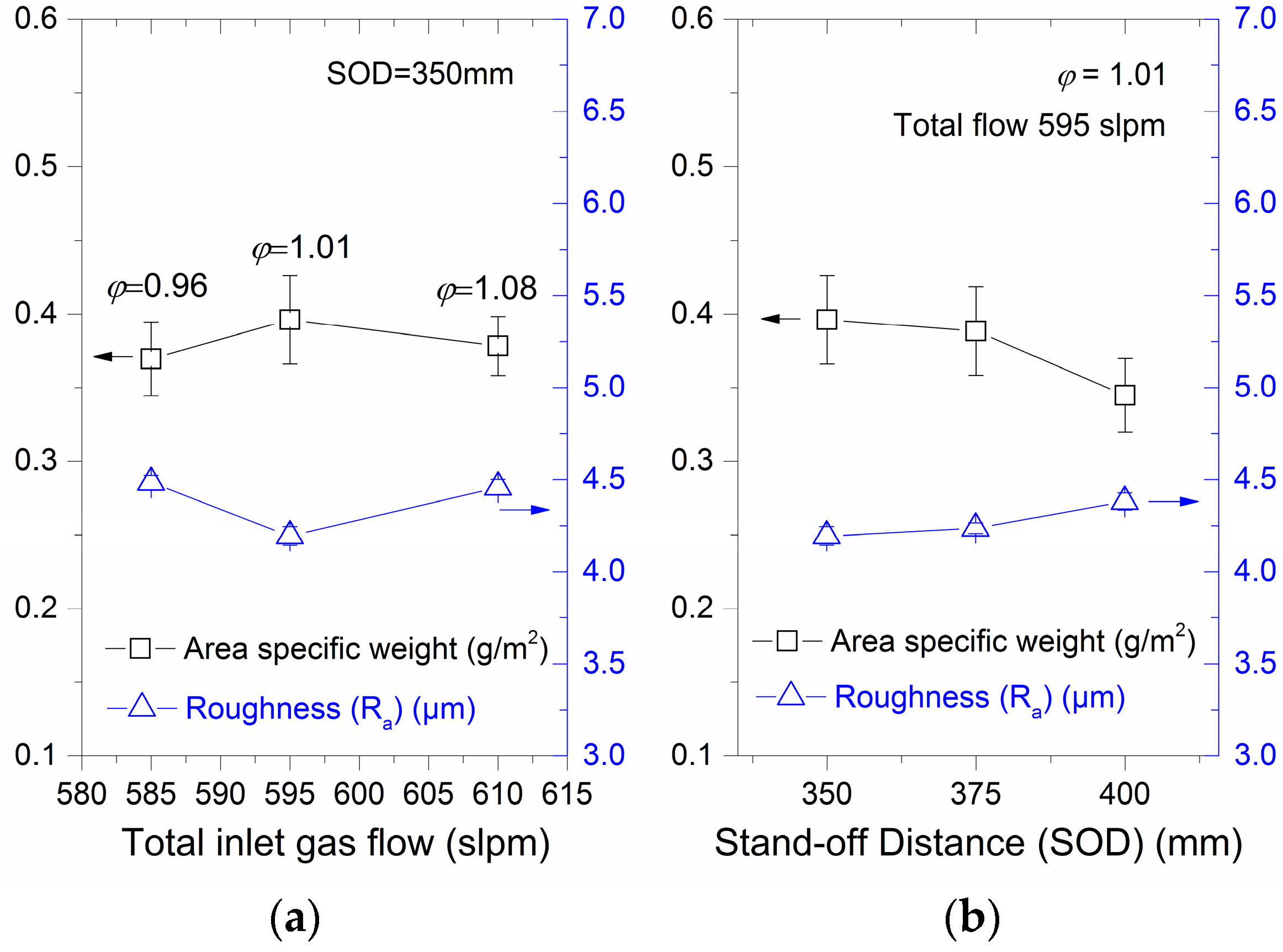
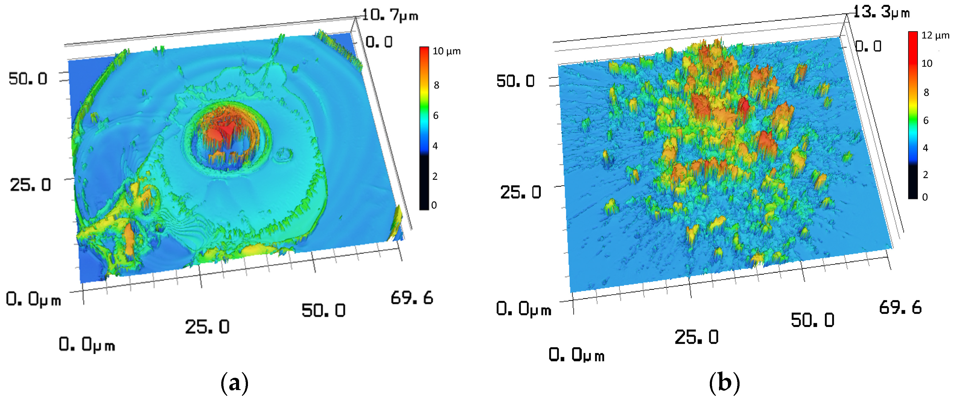
For the assessment of the effect of the chosen oxygen/methane flow rates (#1, #2, and #3 in Table 2), the area specific weight (ASW) and average roughness (Ra) of the coatings were evaluated. A correlation was found between the ASW and the roughness values of the as-sprayed coatings; the maximum ASW was calculated for the coating with the minimum Ra and vice versa, and was employed as an indirect method for optimization (Figure 2a,b). It is reasonable to ascribe the high ASW—low roughness combination of the coating to the well-molten, flattened, and bonded particles, which can be translated to the high particle temperature and velocities delivered by the combustion of the fuel/oxygen mixture. The particles will otherwise remain in the non-molten/partially-molten state and they will either bounce-off the substrate resulting in a reduction in the ASW or will stick to it, but the latter will lead to a rougher surface finish. For ease of understanding, a comparison of the smooth and rough surface morphologies of HVOF sprayed molten and non-molten/partially molten single Yb2Si2O7 splats, respectively, is given in Figure 3a,b.
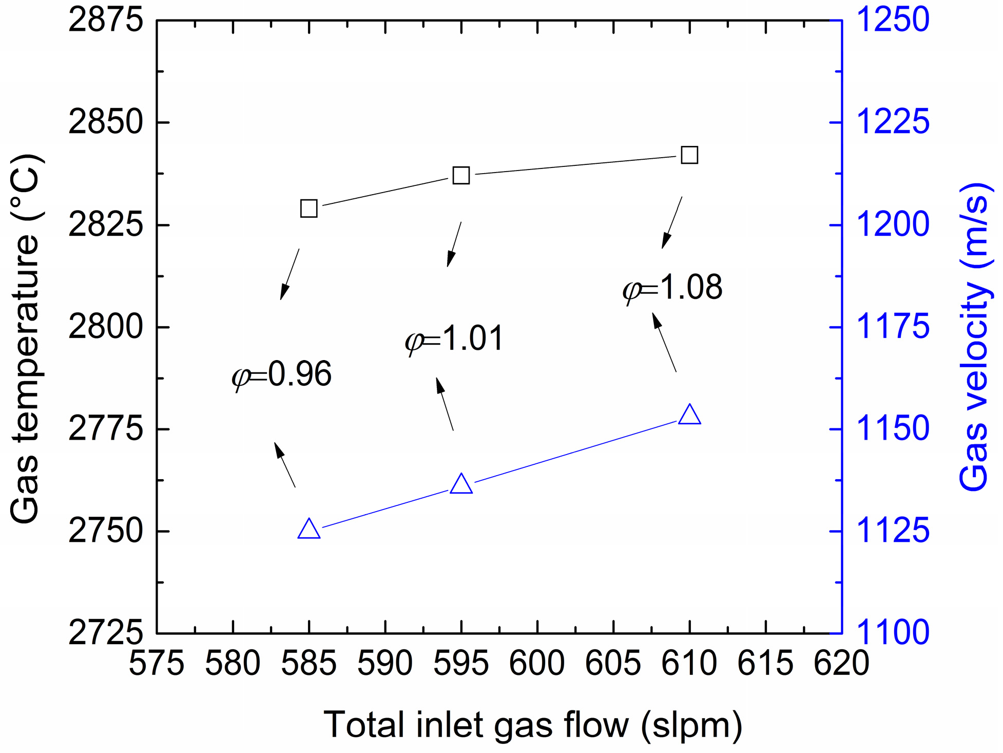
Based on these assumptions, it can be interpreted from Figure 2a that the maximum particle temperature and velocities were reached at the total gas flow of 595 slpm, while the increased total flow rate (610 slpm) induced a reduction. The equivalence ratio of the fuel/oxygen mixtures, which is described as the actual fuel/oxygen ratio divided by the stoichiometric fuel/oxygen ratio (φ = (fuel/oxygen)/(fuel/oxygen)stoichiometric, fuel rich if φ > 1, fuel lean if φ < 1 and stoichiometric if φ = 1) is also noted on the graph, indicating that the selected fuel/oxygen ratios are close to a stoichiometric mixture. The stoichiometric mixture (φ = 1) is suggested by the combustion thermodynamics to obtain a maximum adiabatic flame temperature from the combustion of a hydrocarbon fuel at a given chamber pressure [24]. Furthermore, the relevance of the stoichiometric fuel/oxygen ratios (or slightly fuel-rich mixtures) to the maximum particle temperature and velocities in the HVOF process has been revealed in the literature [25,26,27]. On the other hand, no general agreement was found regarding the effect of the total inlet gas flow on the particle temperature and velocities. Zhao et al. and Turunen et al. [28,29] reported an increase in both the particle temperature and velocities with increasing total gas flow rates associated with higher burning enthalpy and gas expansion. However, Picas et al. [26] showed a decrease in particle temperatures when fuel rates exceeded a certain level. Moreover, Guo et al. [30], who worked with methane fuel similar to the current study, recorded increasing particle velocities with rising fuel flow rates and yet they found that the particle temperatures gradually reduced at the same conditions. The decreasing temperatures of the particles at higher fuel flow rates were thus attributed to their reducing dwell time in the flame, which can also explain the abovementioned changes in the ASW and roughness values at the highest total flow rate. To further check this, the gas temperature and velocities were calculated for the chosen constant oxygen and increasing methane flow rates (#1, #2, and #3 in Table 2) in this study and the results are shown in Figure 4. Accordingly, the highest gas velocity and the highest gas temperature are found at the highest total gas flow (φ = 1.08). It can be expected that the temperature would drop again if φ was further increased. Considering that the optimum roughness and ASW values are obtained applying a gas mixture of an almost stoichiometric composition (φ = 1.01) in this work, it is clear that the maxima of the roughness and ASW are seen at specific particle velocities and temperatures, and beyond these, begin to decrease. Thus, the highest temperature and velocity values are not the optimum parameters in this respect.
Using this optimum fuel/oxygen mixture, the Yb2Si2O7 coatings were also sprayed at different stand-off distances (SODs) (Figure 2b). The SOD < 350 mm yielded lower ASW values of the coatings and thus these results are not shown in the graph. Furthermore, almost no difference was observed by increasing the SOD from 350 mm to 375 mm. However, a slight decrease in the ASW and a simultaneous increase in the roughness were obtained at 400 mm SOD. The effect of the SOD will be further discussed below.
3.2. Microstructure, Crystallinity and Phase Composition
Figure 5a–e shows the low magnification cross-section microstructures of five Yb2Si2O7 coatings sprayed with different total flow rates and SODs, and the measured porosity of these coatings via image analysis are given in. The microstructures of all coatings were found to be fairly dense and similar. Nevertheless, the lowest porosity content was measured at φ = 1.01 with 350 mm SOD (#2). This finding confirms the prior discussions regarding the highest ASW and the lowest roughness recorded due to well-molten particles with the same spray parameters. On the other hand, the highest porosity was measured at φ = 1.01 with 400 mm SOD (#5). Obviously, particles start to significantly cool down/slow down beyond 375 mm and more particles bounce off the substrate. Supportively, Figure 5e reveals a thinner coating with a rougher surface finish due to the presence of a high amount of non-molten or partially molten particles in the microstructure.
Figure 6 shows the XRD patterns of the HVOF sprayed Yb2Si2O7 deposits. The indexed peaks in the patterns suggest the presence of monoclinic Yb2Si2O7 (C2/m, JCPDS No 01-082-0734) and Yb2SiO5 (I2/a, JCPDS No 00-040-0386) phases in the feedstock. The broad humps at 2θ angle ranges of 24°–38° and 40°–70° imply that the as-sprayed deposit contains amorphous phases, as expected and discussed in the previous study [17]. A quantitative comparison of the amorphous contents of the as-sprayed coatings determined by the PONKCS method is shown in Table 4. The results were found to be quite similar to each other within the estimated margin of error of 5%, as well as higher than in the earlier work (48% amorphous content at 325 mm SOD [17]). This is probably due to the smaller particle size distribution of the feedstock in the current work, as well as the longer SOD, which is selected to be a minimum of 350 mm to obtain higher ASWs.
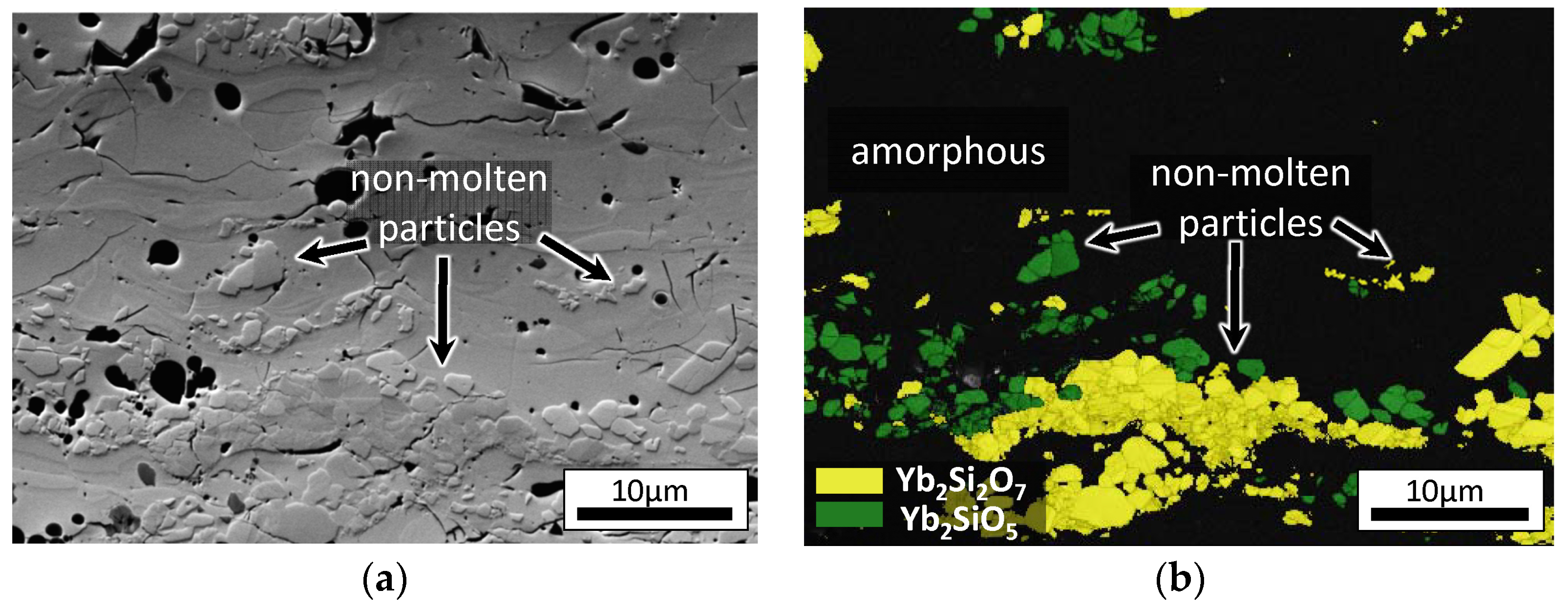
The crystalline/non-crystalline areas in the coatings were also investigated by an EBSD analysis. The analysis was performed on the cross-section of the HVOF sprayed coating #2 as an example (Figure 7a,b). The non-molten/partially molten particles embedded in a molten and well-bonded coating matrix are observed in Figure 7a, and Figure 7b shows a phase map of the same coating area. The latter clearly demonstrates that the molten matrix is non-crystalline and hence yields no diffraction (black regions), whereas the non-molten particles preserved their crystallinity. The Yb2Si2O7 and Yb2SiO5 phases were indexed for these non-molten particles, supporting the XRD analysis results.
3.3. Adhesion of HVOF Sprayed Top Coat on Si Bond Coat
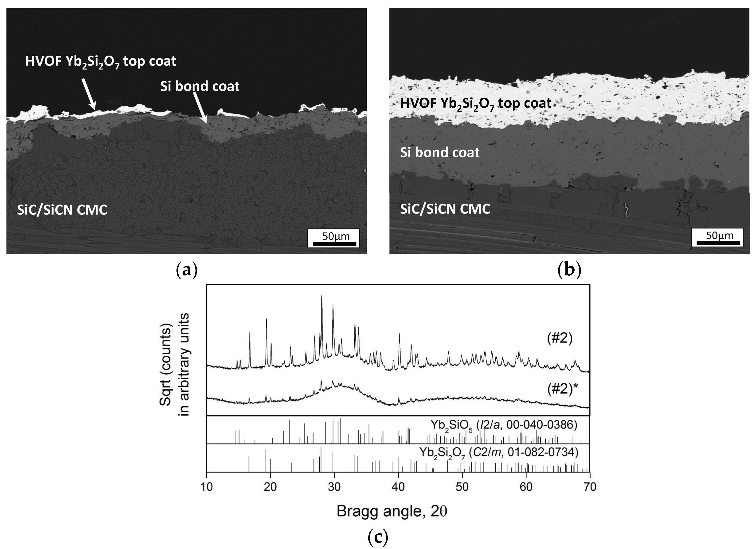
The Si coatings with a thickness of 60 µm were sprayed by the APS with the given parameters in Table 3 on SiC/SiCN CMC substrates. Afterward, the Yb2Si2O7 was sprayed using the HVOF parameters (#2) on the Si bond coat and Figure 8a shows the cross-section micrograph of this trial. A decreased thickness of the Si bond coat and the Yb2Si2O7 coated/uncoated patches on top of it clearly suggest that the sprayed Yb2Si2O7 particles eroded the brittle Si layer. A deposition could be achieved later by reducing the particle size of the feedstock, due to the ease of melting fine powders, which results in a superior wetting behavior (Figure 8b). A higher density of the coating is also evident from the microstructure. However, as shown with the XRD patterns in Figure 8c, reducing the particle size is also accompanied by a decrease in the coating crystallinity. According to the PONCKS analysis, this coating has a more than 90% amorphous content and yet no vertical crack formation was observed in the as-sprayed state, as well as the after thermal cycling, as shown in Figure 9a. This behaviour was found to be different to that of the APS deposited highly amorphous Yb2Si2O7coatings, as they are vertically cracked, even after the deposition (such a microstructure can be seen in [17]). The cracking in the APS coating is attributed to its higher thermal expansion (particularly if the Yb2SiO5 is present) than the substrate, which results in the development of the tensile stresses in the coating during cooling from high deposition temperatures (above 500 °C) to room temperature. Possible reasons preventing the similar crack formation in the HVOF sprayed coatings in the as sprayed state and after the thermal cycling are: (i) a higher porosity in the HVOF coatings than the APS coatings (in the range of 5%–8% higher in the former, based on the image analysis), which provides the HVOF coatings with some strain tolerance; (ii) lower HVOF deposition temperatures (150–170 °C) which diminishes the magnitude of stresses due to the reduced cooling rates; (iii) the possibly lower content of Yb2SiO5 with a higher thermal expansion in the HVOF coatings than the APS coatings due to lower deposition temperatures, which hinders the evaporation of Si-bearing species; and finally (iv) the possible compressive stress growth in the HVOF coatings as a result of the peening effect of the particles on the substrate or on the previously deposited layer.
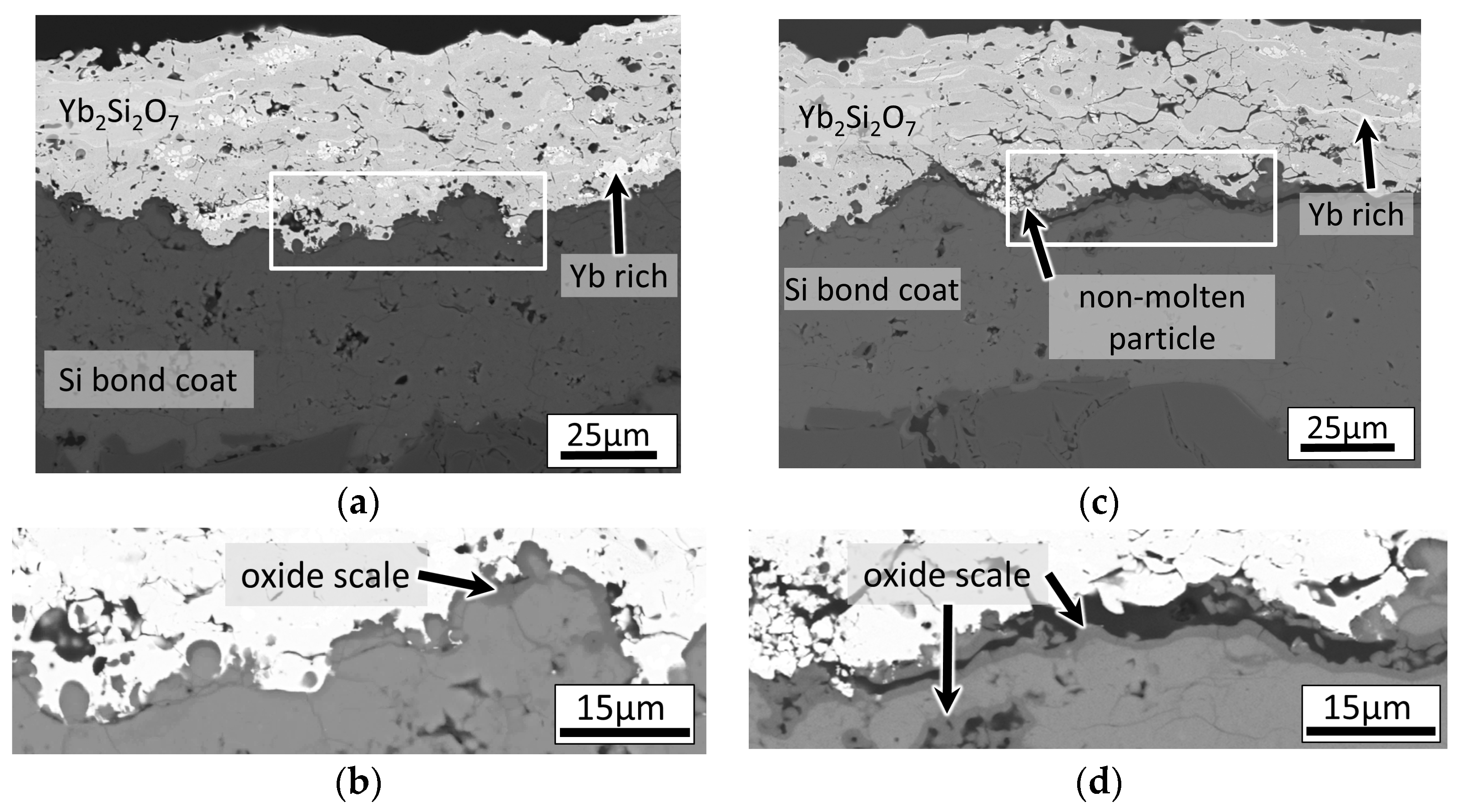
Nevertheless, although the HVOF coating remained attached to the bond coat after cycling and built no vertical cracks (Figure 9a), in a few locations, where a particularly loose non-molten particle is in contact with the bond coat, partial delaminations were observed (Figure 9c). It is probable that the reduced interfacial bonding strength by the presence of these loosely bonded particles eases the crack propagation and hence the delamination.
4. Conclusions
The HVOF process was used for the deposition of the Yb2Si2O7 coatings, and the effects of the oxygen/methane ratio and stand-off distance on the coating microstructure and crystallinity were discussed. The concurrent changes in the area specific weight and arithmetic mean roughness associated with the presence of molten/non-molten particles in the coatings at different process conditions (e.g., fuel lean or rich conditions) were interpreted. Accordingly, an equivalence ratio of 1.01 was found to yield the highest area specific weight when it was combined with a stand-off distance of 350–375 mm. The amorphous content of the HVOF sprayed coatings was found to be in the range of 65%–73% by PONKCS analysis, and the EBSD analysis clearly demonstrates that the non-molten particles explain this partial crystallinity. However, despite the fact that the depositions successfully worked on the metallic substrates, under the same deposition conditions, the silicon bond coat layer was found to be eroded. It was shown that this could be avoided by decreasing the particle size of the Yb2Si2O7 feedstock; however, by doing that, the amorphous content of the coating is further increased. Nevertheless, no vertical cracks were observed in this highly amorphous and dense as-deposited coating, revealing the advantage of HVOF deposition over the APS, which was elaborated in the results and discussion section. The thermal cycling test of this highly amorphous coating, however, suggested that non-molten particles at the Si/Yb2Si2O7 interface may be unfavorable for the adhesion, as their presence at the interface coincided with the delamination cracks. Consequently, if the bonding of the HVOF top coat to the Si bond coat can be improved, the conventional HVOF method can be used for the manufacturing of silicate EBCs without requiring very high deposition temperatures as is the case in the plasma spraying process. Current investigations are looking at different methods to develop a well-adhered interface and steam cycling tests are planned for the validation of the EBCs.
Acknowledgments
The authors thank K.H.R., R.L. and F.K. (all in IEK-1, JÜLICH) for their support on manufacturing the coatings. Special thanks to E. Wessel (IEK-2, JÜLICH) for performing EBSD analysis.
Author Contributions
E.B., G.M., and R.V. conceived and designed the experiments, D.K. contributed the materials, E.B. performed the experiments, E.B., G.M., and Y.S. analyzed the data, and E.B. wrote the paper.
Conflicts of Interest
The authors declare no conflict of interest.
References
- Gupta, A.K.; Lilley, D.G. Combustion and environmental challenges for gas turbines in the 1990s. J. Propuls. Power 1994, 10, 137–147. [Google Scholar] [CrossRef]
- Jacobson, N.S.; Smialek, J.L.; Fox, D.S.; Opila, E.J. Durability of Silica-Protected Ceramics in Combustion Atmospheres; American Ceramic Society: Westerville, OH, USA, 1995. [Google Scholar]
- Ohnabe, H.; Masaki, S.; Onozuka, M.; Miyahara, K.; Sasa, T. Potential application of ceramic matrix composites to aero-engine components. Compos. Part A Appl. Sci. Manuf. 1999, 30, 489–496. [Google Scholar] [CrossRef]
- Bansal, N.P. Handbook of Ceramic Composites; Bansal, N.P., Ed.; Kluwer: Boston, MA, USA, 2005. [Google Scholar]
- Bansal, N.P.; Lamon, J. Ceramic Matrix Composites: Materials, Modeling and Technology; Wiley: Hoboken, NJ, USA, 2014. [Google Scholar]
- Opila, E.J.; Hann, R.E. Paralinear oxidation of CVD SiC in water vapor. J. Am. Ceram. Soc. 1997, 80, 197–205. [Google Scholar] [CrossRef]
- Robinson, R.C.; Smialek, J.L. SiC recession caused by SiO2 scale volatility under combustion conditions: I, experimental results and empirical model. J. Am. Ceram. Soc. 1999, 82, 1817–1825. [Google Scholar] [CrossRef]
- Smialek, J.L.; Robinson, R.C.; Opila, E.J.; Fox, D.S.; Jacobson, N.S. SiC and Si3N4 recession due to SiO2 scale volatility under combustor conditions. Adv. Compos. Mater. 1999, 8, 33–45. [Google Scholar] [CrossRef]
- Opila, E.J.; Smialek, J.L.; Robinson, R.C.; Fox, D.S.; Jacobson, N.S. SiC recession caused by SiO2 scale volatility under combustion conditions: II, thermodynamics and gaseous-diffusion model. J. Am. Ceram. Soc. 1999, 82, 1826–1834. [Google Scholar] [CrossRef]
- Lee, K.N. Current status of environmental barrier coatings for Si-based ceramics. Surf. Coat. Technol. 2000, 133, 1–7. [Google Scholar] [CrossRef]
- Eaton, H.E.; Linsey, G.D.; More, K.L.; Kimmel, J.B.; Price, J.R.; Miriyala, N. EBC Protection of SiC/SiC Composites in the Gas Turbine Combustion Environment. In Proceedings of the ASME Turbo Expo 2000: Power for Land, Sea, and Air, Munich, Germany, 8–11 May 2000. [Google Scholar]
- Eaton, H.E.; Linsey, G.D.; Sun, E.Y.; More, K.L.; Kimmel, J.B.; Price, J.R.; Miriyala, N. EBC Protection of SiC/SiC Composites in the Gas Turbine Combustion Environment: Continuing Evaluation and Refurbishment Considerations. In Proceedings of the ASME Turbo Expo 2001: Power for Land, Sea, and Air, New Orleans, LA, USA, 4–7 June 2001. [Google Scholar]
- Lee, K.N.; Fox, D.S.; Eldridge, J.I.; Zhu, D.; Robinson, R.C.; Bansal, N.P.; Miller, R.A. Upper temperature limit of environmental barrier coatings based on mullite and BSAS. J. Am. Ceram. Soc. 2003, 86, 1299–1306. [Google Scholar] [CrossRef]
- Lee, K.N.; Fox, D.S.; Bansal, N.P. Rare earth silicate environmental barrier coatings for SiC/SiC composites and Si3N4 ceramics. J. Eur. Ceram. Soc. 2005, 25, 1705–1715. [Google Scholar] [CrossRef]
- Richards, B.T.; Zhao, H.; Wadley, H.N.G. Structure, composition, and defect control during plasma spray deposition of ytterbium silicate coatings. J. Mater. Sci. 2015, 50, 7939–7957. [Google Scholar] [CrossRef]
- Richards, B.T.; Young, K.A.; de Francqueville, F.; Sehr, S.; Begley, M.R.; Wadley, H.N.G. Response of ytterbium disilicate–silicon environmental barrier coatings to thermal cycling in water vapor. Acta Mater. 2016, 106, 1–14. [Google Scholar] [CrossRef]
- Bakan, E.; Marcano, D.; Zhou, D.; Sohn, Y.J.; Mauer, G.; Vaßen, R. Yb2Si2O7 coatings deposited by various thermal spray techniques: A preliminary comparative study. J. Therm. Spray Technol. 2017. submitted. [Google Scholar]
- Korpiola, K.; Hirvonen, J.P.; Laas, L.; Rossi, F. The influence of nozzle design on HVOF exit gas velocity and coating microstructure. J. Therm. Spray Technol. 1997, 6, 469–474. [Google Scholar] [CrossRef]
- Mainzer, B.; Friess, M.; Jemmali, R.; Koch, D. Development of polyvinylsilazane-derived ceramic matrix composites based on Tyranno SA3 fibers. J. Ceram. Soc. Jpn. 2016, 124, 1035–1041. [Google Scholar] [CrossRef]
- Gordon, S.; MeBride, B.J. Computer Program for Calculation of Complex Chemical Equilibrium Compositions and Applications. I. Analysis; NASA Reference Publications; Lewis Research Center: Cleveland, OH, USA, 1994; pp. 25–32. [Google Scholar]
- Scarlett, N.V.Y.; Madsen, I.C. Quantification of phases with partial or no known crystal structures. Powder Diffr. 2006, 21, 278–284. [Google Scholar] [CrossRef]
- ISO 4288:1996–Geometrical Product Specifications (GPS)–Surface Texture: Profile Method–Rules and Procedures for the Assessment of Surface Texture; International Organization for Standardization: Geneva, Switzerland, 1996.
- ISO 3274:1996–Geometrical Product Specifications (GPS)–Surface Texture: Profile Method–Nominal Characteristics of Contact (Stylus) Instruments; International Organization for Standardization: Geneva, Switzerland, 1996.
- Glassman, I. Combustion; Elsevier Science: Amsterdam, The Netherlands, 1997. [Google Scholar]
- Li, M.; Christofides, P.D. Multi-scale modeling and analysis of an industrial HVOF thermal spray process. Chem. Eng. Sci. 2005, 60, 3649–3669. [Google Scholar] [CrossRef]
- Picas, J.A.; Punset, M.; Baile, M.T.; Martín, E.; Forn, A. Effect of oxygen/fuel ratio on the in-flight particle parameters and properties of HVOF WC-CoCr coatings. Surf. Coat. Technol. 2011, 205, S364–S368. [Google Scholar] [CrossRef]
- Cheng, D.; Xu, Q.; Tapaga, G.; Lavernia, E.J. A numerical study of high-velocity oxygen fuel thermal spraying process. Part I: Gas phase dynamics. Metall. Mater. Trans. A 2001, 32, 1609–1620. [Google Scholar] [CrossRef]
- Zhao, L.; Maurer, M.; Fischer, F.; Lugscheider, E. Study of HVOF spraying of WC–CoCr using on-line particle monitoring. Surf. Coat. Technol. 2004, 185, 160–165. [Google Scholar] [CrossRef]
- Turunen, E.; Varis, T.; Hannula, S.P.; Vaidya, A.; Kulkarni, A.; Gutleber, J.; Sampath, S.; Herman, H. On the role of particle state and deposition procedure on mechanical, tribological and dielectric response of high velocity oxy-fuel sprayed alumina coatings. Mater. Sci. Eng. A 2006, 415, 1–11. [Google Scholar] [CrossRef]
- Guo, X.; Planche, M.-P.; Chen, J.; Liao, H. Relationships between in-flight particle characteristics and properties of HVOF sprayed WC-CoCr coatings. J. Mater. Process. Technol. 2014, 214, 456–461. [Google Scholar] [CrossRef]
Figure 1.
X-ray diffractogram of the Yb2Si2O7 feedstock.

Figure 2.
ASW and roughness of the HVOF sprayed Yb2Si2O7 coatings as a function of the total inlet gas flow (a) and (b) the stand-off distance. Error bars of the ASW values calculated from the standard deviation of four substrate area measurements and error bars of the roughness show the standard deviation of 10 profile measurements (λc = 2.5 mm).

Figure 3.
3D-surface morphology of HVOF-sprayed (a) molten (φ = 1.01) and (b) non-molten (φ = 0.96) Yb2Si2O7 single splats on Si wafer. The images were produced using a confocal laser microscope.
Figure 3.
3D-surface morphology of HVOF-sprayed (a) molten (φ = 1.01) and (b) non-molten (φ = 0.96) Yb2Si2O7 single splats on Si wafer. The images were produced using a confocal laser microscope.

Figure 4.
Calculated gas temperature and velocities in the throat of the nozzle at different total gas flow rates. The oxygen flow is constant at 395 slpm.
Figure 4.
Calculated gas temperature and velocities in the throat of the nozzle at different total gas flow rates. The oxygen flow is constant at 395 slpm.

Figure 5.
Microstructure of HVOF sprayed Yb2Si2O7 coatings with the spray settings of (a) #1; (b) #2; (c) #3; (d) #4; (e) #5.
Figure 5.
Microstructure of HVOF sprayed Yb2Si2O7 coatings with the spray settings of (a) #1; (b) #2; (c) #3; (d) #4; (e) #5.
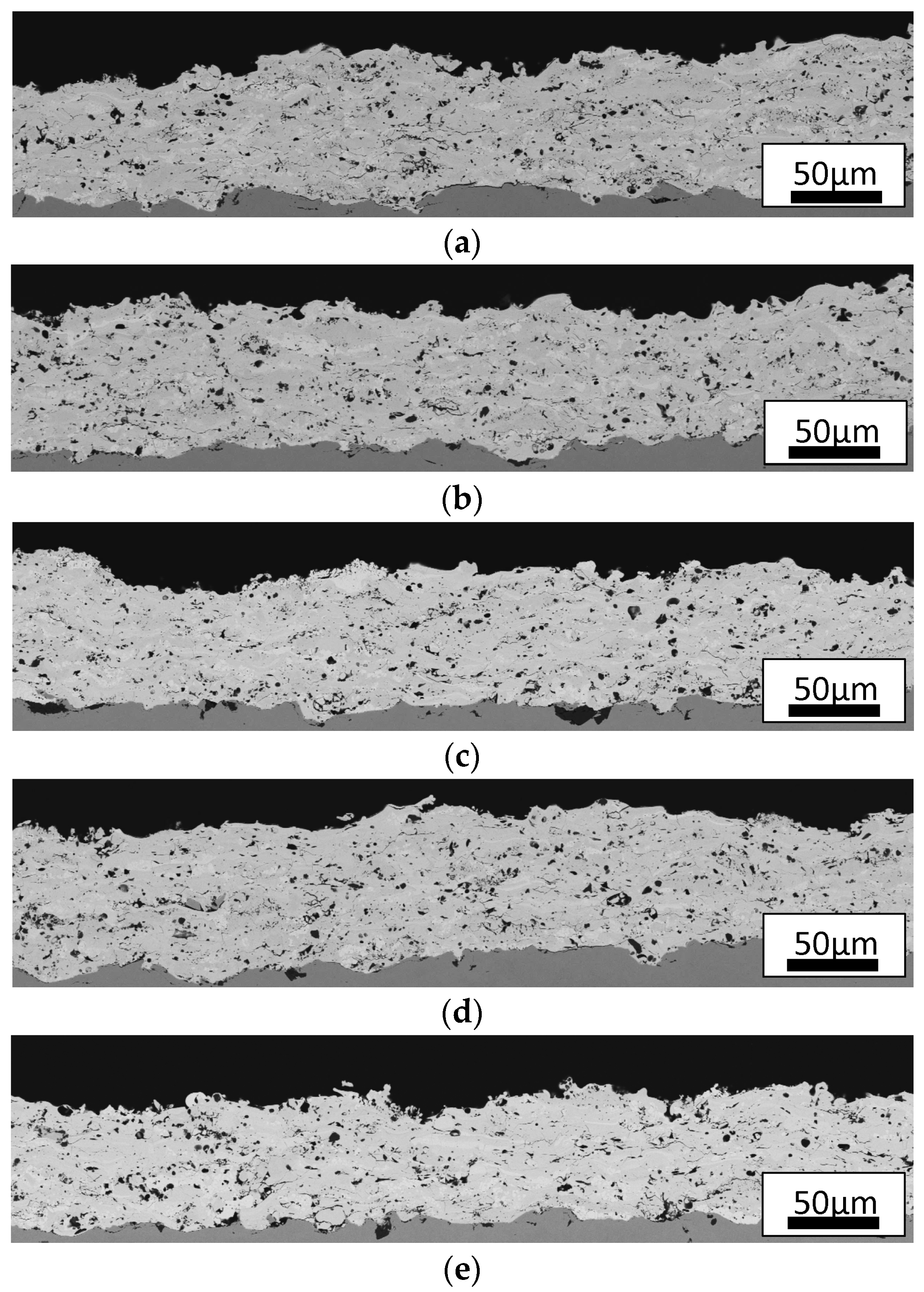
Figure 6.
XRD patterns of HVOF deposited coatings with the given process parameters (#1, #2, #3, #4, #5).
Figure 6.
XRD patterns of HVOF deposited coatings with the given process parameters (#1, #2, #3, #4, #5).
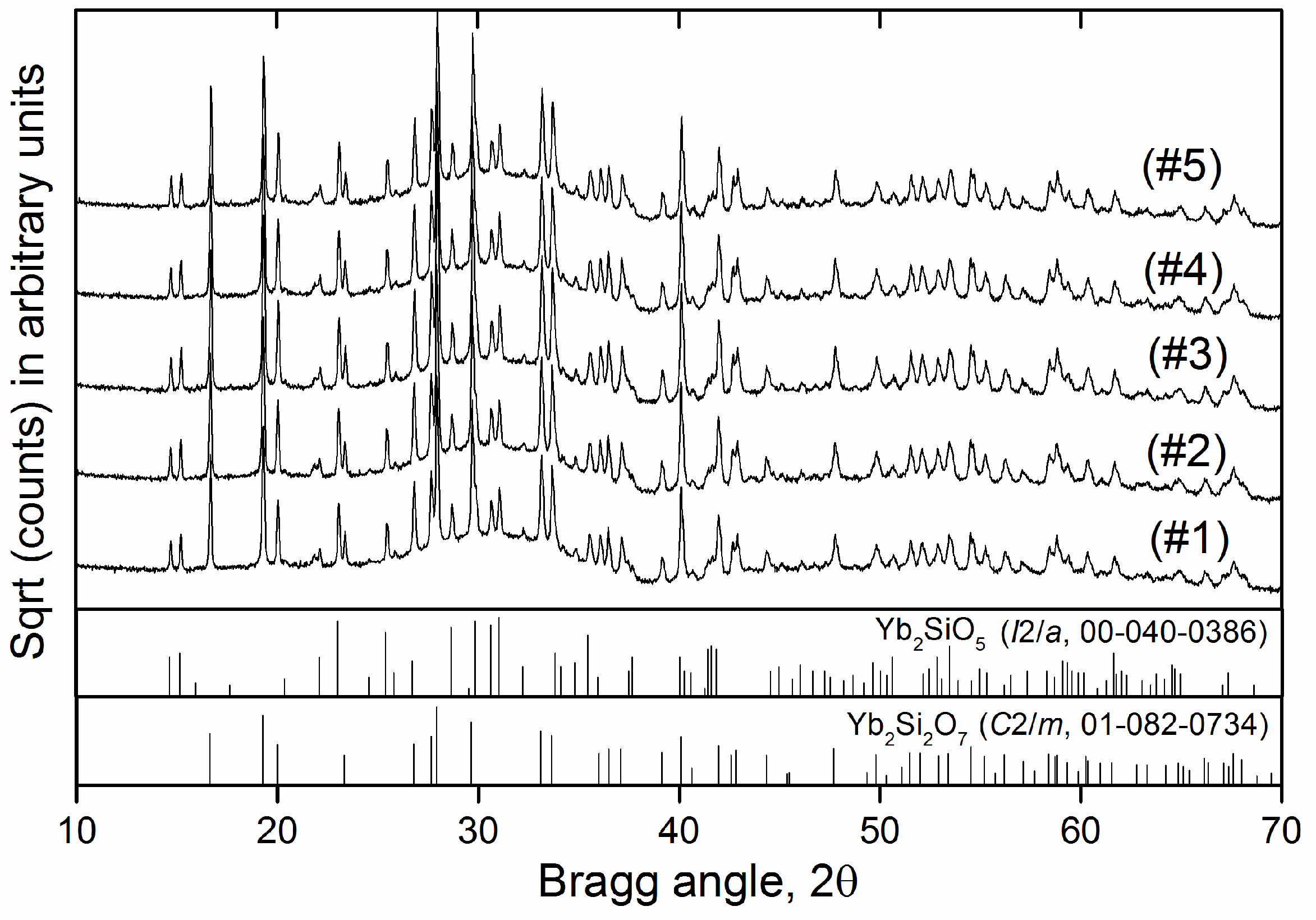
Figure 7.
EBSD analysis results of the Yb2Si2O7 coating (#2): (a) Forescatter diode (FSD) image and (b) phase map.
Figure 7.
EBSD analysis results of the Yb2Si2O7 coating (#2): (a) Forescatter diode (FSD) image and (b) phase map.

Figure 8.
(a,b) Backscattered SEM micrographs of EBC cross-sections. (a) HVOF sprayed Yb2Si2O7 (#2) on Si bond coat; (b) HVOF sprayed Yb2Si2O7 (#2) using reduced particle size (d10 = 17 µm, d50 = 25 µm, d90 = 34 µm) on Si bond coat. (c) Comparison of the XRD patterns of the Yb2Si2O7 coatings deposited using same spray parameters (#2) but different particle sizes. (#2) and (#2) * denote original and reduced particle sizes, respectively.

Figure 9.
Backscattered SEM micrographs of EBC cross-section after five cycles between 1200 °C and room temperature with 20 h high temperature dwell time. Images (a,c) are taken from the different regions of the same sample. White rectangles in (a,c) indicate the region of high-magnification images shown below (b,d), in which oxidation of the silicon coating at the Si/Yb2Si2O7 interface as well as on the pore surfaces is clearly visible via darker image contrast.


Table 1.
Manufacturing method and particle size of the feedstock powders measured with laser diffraction (LA-950-V2, Horiba Ltd., Tokyo, Japan).
Table 1.
Manufacturing method and particle size of the feedstock powders measured with laser diffraction (LA-950-V2, Horiba Ltd., Tokyo, Japan).
| Powder | Manufacturing Method | Particle Size (µm) | ||
|---|---|---|---|---|
| d10 | d50 | d90 | ||
| Si | Fused-crushed | 28 | 40 | 59 |
| Yb2Si2O7 | Agglomerated-sintered | 22 | 34 | 52 |
Table 2.
HVOF spray parameters for processing Yb2Si2O7 coatings.
| Number of Spray Sets | Oxygen Flow (slpm) | Methane Flow (slpm) | Equivalence Ratio (φ) * | Air Flow (slpm) | Powder Feed Rate (%) | Spray Distance (mm) | Robot Velocity (mm/s) | Substrate Temperature (°C) |
|---|---|---|---|---|---|---|---|---|
| #1 | 395 | 190 | 0.96 | 250 | 20 | 350 | 1200 | 135 |
| #2 | 395 | 200 | 1.01 | 250 | 20 | 350 | 1200 | 150 |
| #3 | 395 | 215 | 1.08 | 250 | 20 | 350 | 1200 | 155 |
| #4 | 395 | 200 | 1.01 | 250 | 20 | 375 | 1200 | 130 |
| #5 | 395 | 200 | 1.01 | 250 | 20 | 400 | 1200 | 125 |
* φ = (fuel/oxygen)/(fuel/oxygen)stoichiometric.
Table 3.
APS spray parameters for Si deposition.
| Spray Current (A) | Ar Flow Rate (slpm) | Feed Rate (%) | Spray Distance (mm) | Robot Velocity (mm/s) | Substrate Temperature (°C) |
|---|---|---|---|---|---|
| 450 | 50 | 30 | 100 | 500 | 200 |
Table 4.
Measured porosity and amorphous content of the Yb2Si2O7 coatings.
| Number of Spray Sets | Porosity (%) ± SD | Amorphous Content (wt %) |
|---|---|---|
| #1 | 8.0 ± 0.8 | 72 ± 5 |
| #2 | 7.7 ± 0.8 | 73 ± 5 |
| #3 | 8.3 ± 0.6 | 69 ± 5 |
| #4 | 8.1 ± 0.5 | 70 ± 5 |
| #5 | 9.1 ± 1.2 | 65 ± 5 |
© 2017 by the authors. Licensee MDPI, Basel, Switzerland. This article is an open access article distributed under the terms and conditions of the Creative Commons Attribution (CC BY) license (http://creativecommons.org/licenses/by/4.0/).
Share and Cite
MDPI and ACS Style
Bakan, E.; Mauer, G.; Sohn, Y.J.; Koch, D.; Vaßen, R. Application of High-Velocity Oxygen-Fuel (HVOF) Spraying to the Fabrication of Yb-Silicate Environmental Barrier Coatings. Coatings 2017, 7, 55. https://doi.org/10.3390/coatings7040055
AMA Style
Bakan E, Mauer G, Sohn YJ, Koch D, Vaßen R. Application of High-Velocity Oxygen-Fuel (HVOF) Spraying to the Fabrication of Yb-Silicate Environmental Barrier Coatings. Coatings. 2017; 7(4):55. https://doi.org/10.3390/coatings7040055
Chicago/Turabian StyleBakan, Emine, Georg Mauer, Yoo Jung Sohn, Dietmar Koch, and Robert Vaßen. 2017. "Application of High-Velocity Oxygen-Fuel (HVOF) Spraying to the Fabrication of Yb-Silicate Environmental Barrier Coatings" Coatings 7, no. 4: 55. https://doi.org/10.3390/coatings7040055
Note that from the first issue of 2016, this journal uses article numbers instead of page numbers. See further details here.